WO2017018008A1 - Dispositif de codage, contrôleur de mémoire, système de communication et procédé de codage - Google Patents
Dispositif de codage, contrôleur de mémoire, système de communication et procédé de codage Download PDFInfo
- Publication number
- WO2017018008A1 WO2017018008A1 PCT/JP2016/062159 JP2016062159W WO2017018008A1 WO 2017018008 A1 WO2017018008 A1 WO 2017018008A1 JP 2016062159 W JP2016062159 W JP 2016062159W WO 2017018008 A1 WO2017018008 A1 WO 2017018008A1
- Authority
- WO
- WIPO (PCT)
- Prior art keywords
- parity
- candidate
- unit
- data
- value
- Prior art date
- Legal status (The legal status is an assumption and is not a legal conclusion. Google has not performed a legal analysis and makes no representation as to the accuracy of the status listed.)
- Ceased
Links
Images













Classifications
-
- G—PHYSICS
- G06—COMPUTING OR CALCULATING; COUNTING
- G06F—ELECTRIC DIGITAL DATA PROCESSING
- G06F11/00—Error detection; Error correction; Monitoring
- G06F11/07—Responding to the occurrence of a fault, e.g. fault tolerance
- G06F11/08—Error detection or correction by redundancy in data representation, e.g. by using checking codes
- G06F11/10—Adding special bits or symbols to the coded information, e.g. parity check, casting out 9's or 11's
-
- G—PHYSICS
- G06—COMPUTING OR CALCULATING; COUNTING
- G06F—ELECTRIC DIGITAL DATA PROCESSING
- G06F11/00—Error detection; Error correction; Monitoring
- G06F11/07—Responding to the occurrence of a fault, e.g. fault tolerance
- G06F11/08—Error detection or correction by redundancy in data representation, e.g. by using checking codes
- G06F11/10—Adding special bits or symbols to the coded information, e.g. parity check, casting out 9's or 11's
- G06F11/1008—Adding special bits or symbols to the coded information, e.g. parity check, casting out 9's or 11's in individual solid state devices
- G06F11/1012—Adding special bits or symbols to the coded information, e.g. parity check, casting out 9's or 11's in individual solid state devices using codes or arrangements adapted for a specific type of error
-
- G—PHYSICS
- G06—COMPUTING OR CALCULATING; COUNTING
- G06F—ELECTRIC DIGITAL DATA PROCESSING
- G06F12/00—Accessing, addressing or allocating within memory systems or architectures
- G06F12/16—Protection against loss of memory contents
-
- H—ELECTRICITY
- H03—ELECTRONIC CIRCUITRY
- H03M—CODING; DECODING; CODE CONVERSION IN GENERAL
- H03M13/00—Coding, decoding or code conversion, for error detection or error correction; Coding theory basic assumptions; Coding bounds; Error probability evaluation methods; Channel models; Simulation or testing of codes
- H03M13/03—Error detection or forward error correction by redundancy in data representation, i.e. code words containing more digits than the source words
- H03M13/05—Error detection or forward error correction by redundancy in data representation, i.e. code words containing more digits than the source words using block codes, i.e. a predetermined number of check bits joined to a predetermined number of information bits
- H03M13/09—Error detection only, e.g. using cyclic redundancy check [CRC] codes or single parity bit
- H03M13/095—Error detection codes other than CRC and single parity bit codes
-
- H—ELECTRICITY
- H03—ELECTRONIC CIRCUITRY
- H03M—CODING; DECODING; CODE CONVERSION IN GENERAL
- H03M13/00—Coding, decoding or code conversion, for error detection or error correction; Coding theory basic assumptions; Coding bounds; Error probability evaluation methods; Channel models; Simulation or testing of codes
- H03M13/35—Unequal or adaptive error protection, e.g. by providing a different level of protection according to significance of source information or by adapting the coding according to the change of transmission channel characteristics
-
- H—ELECTRICITY
- H03—ELECTRONIC CIRCUITRY
- H03M—CODING; DECODING; CODE CONVERSION IN GENERAL
- H03M13/00—Coding, decoding or code conversion, for error detection or error correction; Coding theory basic assumptions; Coding bounds; Error probability evaluation methods; Channel models; Simulation or testing of codes
- H03M13/61—Aspects and characteristics of methods and arrangements for error correction or error detection, not provided for otherwise
- H03M13/611—Specific encoding aspects, e.g. encoding by means of decoding
-
- G—PHYSICS
- G11—INFORMATION STORAGE
- G11C—STATIC STORES
- G11C16/00—Erasable programmable read-only memories
- G11C16/02—Erasable programmable read-only memories electrically programmable
-
- G—PHYSICS
- G11—INFORMATION STORAGE
- G11C—STATIC STORES
- G11C16/00—Erasable programmable read-only memories
- G11C16/02—Erasable programmable read-only memories electrically programmable
- G11C16/06—Auxiliary circuits, e.g. for writing into memory
-
- H—ELECTRICITY
- H03—ELECTRONIC CIRCUITRY
- H03M—CODING; DECODING; CODE CONVERSION IN GENERAL
- H03M13/00—Coding, decoding or code conversion, for error detection or error correction; Coding theory basic assumptions; Coding bounds; Error probability evaluation methods; Channel models; Simulation or testing of codes
- H03M13/03—Error detection or forward error correction by redundancy in data representation, i.e. code words containing more digits than the source words
- H03M13/05—Error detection or forward error correction by redundancy in data representation, i.e. code words containing more digits than the source words using block codes, i.e. a predetermined number of check bits joined to a predetermined number of information bits
- H03M13/09—Error detection only, e.g. using cyclic redundancy check [CRC] codes or single parity bit
-
- H—ELECTRICITY
- H03—ELECTRONIC CIRCUITRY
- H03M—CODING; DECODING; CODE CONVERSION IN GENERAL
- H03M13/00—Coding, decoding or code conversion, for error detection or error correction; Coding theory basic assumptions; Coding bounds; Error probability evaluation methods; Channel models; Simulation or testing of codes
- H03M13/03—Error detection or forward error correction by redundancy in data representation, i.e. code words containing more digits than the source words
- H03M13/05—Error detection or forward error correction by redundancy in data representation, i.e. code words containing more digits than the source words using block codes, i.e. a predetermined number of check bits joined to a predetermined number of information bits
- H03M13/13—Linear codes
- H03M13/15—Cyclic codes, i.e. cyclic shifts of codewords produce other codewords, e.g. codes defined by a generator polynomial, Bose-Chaudhuri-Hocquenghem [BCH] codes
- H03M13/151—Cyclic codes, i.e. cyclic shifts of codewords produce other codewords, e.g. codes defined by a generator polynomial, Bose-Chaudhuri-Hocquenghem [BCH] codes using error location or error correction polynomials
- H03M13/1515—Reed-Solomon codes
-
- H—ELECTRICITY
- H03—ELECTRONIC CIRCUITRY
- H03M—CODING; DECODING; CODE CONVERSION IN GENERAL
- H03M13/00—Coding, decoding or code conversion, for error detection or error correction; Coding theory basic assumptions; Coding bounds; Error probability evaluation methods; Channel models; Simulation or testing of codes
- H03M13/03—Error detection or forward error correction by redundancy in data representation, i.e. code words containing more digits than the source words
- H03M13/05—Error detection or forward error correction by redundancy in data representation, i.e. code words containing more digits than the source words using block codes, i.e. a predetermined number of check bits joined to a predetermined number of information bits
- H03M13/13—Linear codes
- H03M13/15—Cyclic codes, i.e. cyclic shifts of codewords produce other codewords, e.g. codes defined by a generator polynomial, Bose-Chaudhuri-Hocquenghem [BCH] codes
- H03M13/151—Cyclic codes, i.e. cyclic shifts of codewords produce other codewords, e.g. codes defined by a generator polynomial, Bose-Chaudhuri-Hocquenghem [BCH] codes using error location or error correction polynomials
- H03M13/152—Bose-Chaudhuri-Hocquenghem [BCH] codes
-
- H—ELECTRICITY
- H03—ELECTRONIC CIRCUITRY
- H03M—CODING; DECODING; CODE CONVERSION IN GENERAL
- H03M13/00—Coding, decoding or code conversion, for error detection or error correction; Coding theory basic assumptions; Coding bounds; Error probability evaluation methods; Channel models; Simulation or testing of codes
- H03M13/03—Error detection or forward error correction by redundancy in data representation, i.e. code words containing more digits than the source words
- H03M13/05—Error detection or forward error correction by redundancy in data representation, i.e. code words containing more digits than the source words using block codes, i.e. a predetermined number of check bits joined to a predetermined number of information bits
- H03M13/13—Linear codes
- H03M13/19—Single error correction without using particular properties of the cyclic codes, e.g. Hamming codes, extended or generalised Hamming codes
Definitions
- the present technology relates to an encoding device, a memory controller, a communication system, and an encoding method. Specifically, the present invention relates to an encoding device, a memory controller, a communication system, and an encoding method that encode data and write the data in a memory cell.
- a non-volatile memory may be used as an auxiliary storage device or storage.
- This non-volatile memory is broadly divided into flash memory that supports data access in units of large size and non-volatile random access memory (NVRAM: Non-Volatile RAM) that allows high-speed random access in small units.
- NVRAM Non-Volatile random access memory
- examples of the nonvolatile random access memory include ReRAM (Resistive RAM), PCRAM (Phase-Change RAM), MRAM (Magnetoresistive RAM), and the like.
- Nonvolatile memories have different data retention characteristics when retaining a logical value “0” and different data retention characteristics when retaining a logical value “1”. This data retention characteristic is also called retention.
- a memory controller that performs predetermined conversion processing (inversion, etc.) on user data so that the number of “1” s decreases when the data retention characteristic (retention) of logical value “0” is better (For example, refer to Patent Document 1). This memory controller adds a parity for detecting an error in the user data after the conversion process to the user data and writes it in the memory cell.
- the retention of the memory cell holding the user data is improved by the inversion of the user data.
- the memory controller since the memory controller writes the parity as it is without inverting it, there is a problem that the retention of the memory cell holding the parity is not improved.
- the present technology has been developed in view of such a situation, and an object thereof is to improve data retention characteristics of a memory cell in a memory system that encodes data and writes the data in the memory cell.
- the present technology has been made to solve the above-described problems.
- the first aspect of the present technology provides a first parity for detecting an error in an information section in which a predetermined value is set in a predetermined variable area.
- a parity for detecting an error in the information part in which a value different from the predetermined value is set in the predetermined variable area is generated as a second candidate parity.
- An encoding device including an output unit that outputs a codeword and an encoding method in the device. This brings about the effect that a code word composed of a selected parity satisfying a predetermined condition among the first and second candidate parities and the information section corresponding to the selected parity is output.
- the information unit may include user data input to the first candidate parity generation unit and unused data including the predetermined variable area. This brings about the effect that the parity is generated from the information part in which the variable area is arranged in the area other than the user data.
- the selection unit counts the number of bits having a specific value as a weight in the first candidate parity and the unused data corresponding to the first candidate parity.
- Weight counter a second weight counter that counts the number of bits of the specific value as a weight in the second candidate parity and the unused data corresponding to the second candidate parity, and the first
- a comparison unit that compares the count values of the second weight counter and selects a parity that satisfies the predetermined condition based on the comparison result. As a result, the parity is selected based on the comparison result of the number of bits of a specific value.
- the first aspect further includes a control unit that reads out data written in the memory cell as pre-read data, and the selection unit corresponds to the first candidate parity and the first candidate parity.
- a first rewrite bit number counter that counts the number of bits different from the pre-read data in the unused data as the rewrite bit number, the second candidate parity, and the second candidate parity
- a comparison unit that compares numbers and selects parity that satisfies the predetermined condition based on the comparison result. It may be. As a result, the parity is selected based on the comparison result of the number of rewrite bits.
- the first aspect further includes a control unit that reads out data written in the memory cell as pre-read data, and the selection unit corresponds to the first candidate parity and the first candidate parity.
- a first longest run counter that counts the number of consecutive bits having different values from the pre-read data in the unused data and obtains the maximum value of the count value as the length of the longest run; and the selection unit includes: The number of consecutive bits having different values from the pre-read data in the second candidate parity and the unused data corresponding to the second candidate parity is counted, and the maximum value of the count value is set to the longest run
- the length of the longest run obtained by each of the second longest run counter obtained as the length and each of the first and second longest run counters is compared. Comparison A, and a comparison section for selecting the predetermined condition is satisfied parity based on the results. This brings about the effect that the parity is selected based on the comparison result of the length of the longest run.
- the unused data may be arranged between the user data and the selected parity in the codeword. This brings about the effect that the unused data arranged between the user data and the selected parity is changed.
- the user data may be arranged between the unused data and the selected parity in the codeword. This brings about the effect that the unused data of the code word in which the user data is arranged between the unused data and the selected parity is changed.
- the user data may be distributed in a plurality of areas in the code word. This brings about the effect that the unused data of the code word in which user data is distributed and arranged in a plurality of areas is changed.
- the unused data in the code word may be distributed in a plurality of areas. This brings about the effect that unused data distributed in a plurality of areas is changed.
- the unused data includes the variable region and a fixed region whose value is not changed
- the second candidate parity generation unit includes the information unit in which the value of the variable region is changed.
- the corresponding second candidate parity may be generated. This brings about the effect that the value of the variable area in the unused data is changed.
- variable region may be distributed in a plurality of regions in the codeword. This brings about the effect that variable regions distributed in a plurality of regions are changed.
- the fixed area may be distributed in a plurality of areas in the code word. This brings about the effect that the unused data of the code word in which the fixed area is distributed and arranged in a plurality of areas is changed.
- the first candidate parity generation unit generates the first candidate parity from the information unit
- the second candidate parity generation unit includes the first candidate parity and
- the second candidate parity may be generated by a logical operation with the first parity pattern. This brings about the effect that the second candidate parity is generated by the logical operation of the first candidate parity and the first parity pattern.
- a third candidate parity generation unit that generates a third candidate parity by a logical operation of the second parity pattern and the first candidate parity, the second parity pattern, A fourth candidate parity generation unit that generates a fourth candidate parity by a logical operation with the second candidate parity, and the selection unit includes the first, second, third, and fourth A parity that satisfies a predetermined condition among the candidate parities may be selected as the selected parity.
- a third candidate parity is generated by a logical operation of the second parity pattern and the first candidate parity
- a fourth candidate parity is generated by a logical operation of the second parity pattern and the second candidate parity. It produces the effect of being generated.
- a conversion process for converting the number of bits of a specific value in user data is performed, and either the user data after the conversion process or the user data before the conversion process is converted into the first data.
- a first candidate parity generation unit that generates, as a first candidate parity, a parity for detecting an error in an information unit in which a predetermined value is set in a predetermined variable region
- a second candidate parity generation unit that generates, as a second candidate parity, a parity for detecting an error in the information unit in which a value different from the predetermined value is set in a predetermined variable region
- the first and second A selection unit that selects, as a selection parity, a parity that satisfies a predetermined condition among the candidate parities
- an output unit that outputs a code word including the information unit corresponding to the selection parity and the selection parity to a memory cell as write data
- a memory controller comprising: a read unit that reads read data from the memory cell and decodes the read data.
- a first candidate parity generation unit that generates, as a first candidate parity, a parity for detecting an error in an information unit in which a predetermined value is set in a predetermined variable region
- a second candidate parity generation unit that generates, as a second candidate parity, a parity for detecting an error in the information unit in which a value different from the predetermined value is set in a predetermined variable region
- the first and second A selection unit that selects, as a selection parity, a parity that satisfies a predetermined condition among candidate parities; an output unit that outputs a codeword including the information unit corresponding to the selection parity and the selection parity; and the transmission
- a decoding unit that receives and decodes a received word corresponding to the word.
- FIG. 1 is an overall view showing a configuration example of a memory system according to a first embodiment. It is a figure which shows an example of resistance distribution of the variable resistive element in 1st Embodiment.
- 3 is a block diagram illustrating a configuration example of a memory controller according to the first embodiment.
- FIG. 3 is a block diagram illustrating a functional configuration example of a memory controller according to the first embodiment.
- FIG. It is a figure which shows an example of the generator matrix and codeword in 1st Embodiment. It is a figure which shows an example of the data structure of the code word in 1st Embodiment. It is a block diagram which shows one structural example of the encoding part in 1st Embodiment.
- First embodiment an example of selecting one of candidate parities
- Second Embodiment Example of selecting one of candidate parities based on the number of rewrite bits
- Third embodiment example of selecting one of candidate parities by changing arrangement of selection values
- Fourth embodiment example in which candidate parity is newly generated from parity pattern and candidate parity and one of them is selected
- Fifth Embodiment Example of selecting one of candidate parities based on the length of the longest run
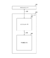
- FIG. 1 is a block diagram illustrating a configuration example of a memory system according to an embodiment.
- This memory system includes a host computer 100 and a storage 200.
- the host computer 100 controls the entire memory system. Specifically, the host computer 100 generates commands and data and supplies them to the storage 200 via the signal line 109. In addition, the host computer 100 receives the read data from the storage 200.
- the command is for controlling the storage 200 and includes, for example, a write command for instructing data writing and a read command for instructing data reading.
- the storage 200 includes a memory controller 300 and a nonvolatile memory 400.
- the memory controller 300 controls the nonvolatile memory 400.
- ECC error detection / correction code
- the memory controller 300 accesses the nonvolatile memory 400 via the signal line 309 and writes the encoded data.
- the memory controller 300 When receiving a read command from the host computer 100, the memory controller 300 accesses the nonvolatile memory 400 via the signal line 309 and reads the encoded data. Then, the memory controller 300 converts (that is, decodes) the encoded data into original data before encoding. At the time of decoding, the memory controller 300 detects and corrects errors in the data based on the ECC. The memory controller 300 supplies the corrected data to the host computer 100.
- the non-volatile memory 400 stores data according to the control of the memory controller 300.
- ReRAM is used as the nonvolatile memory 400.
- the nonvolatile memory 400 includes a plurality of memory cells, and these memory cells are divided into a plurality of blocks.
- the block is an access unit of the nonvolatile memory 400 and is also called a sector.
- Each block is assigned a memory address.
- a flash memory, a PCRAM, an MRAM, or the like may be used as the nonvolatile memory 400 instead of the ReRAM.
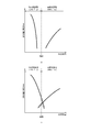
- FIG. 2 is a diagram illustrating an example of the resistance distribution of the variable resistance element of the ReRAM according to the first embodiment.
- the horizontal axis indicates the resistance value
- the vertical axis indicates the relative distribution of the number of cells by the relative value.
- the resistance state of the variable resistance element is roughly divided into two distributions with a predetermined threshold as a boundary. A state where the resistance value is lower than the threshold value is called a low resistance state (LRS: Low-Resistance State), and a state where the resistance value is higher than the threshold value is a high resistance state (HRS: High-Resistance State). Called.
- the nonvolatile memory 400 can rewrite the memory cell by reversibly changing its resistance state by applying a voltage to the variable resistance element. Since the resistance state is maintained even when the voltage application to the memory cell is stopped, the ReRAM can function as a nonvolatile memory.
- each of the variable resistance elements LRS and HRS is associated with either a logical value “0” or a logical value “1”.
- the logical value “1” is associated with the LRS
- the logical value “0” is associated with the HRS. It is arbitrary whether to associate the logical value “0” or the logical value “1” with each state.
- 2a is a diagram showing an example of a resistance distribution of a variable resistance element that is not deteriorated.
- the resistance values of all the memory cells in which “1” is written are lower than the threshold value, and the resistance values of all the memory cells in which “0” are written are higher than the threshold value. For this reason, a bit having the same value as the written value is read, and no read error occurs.
- “b” in FIG. 2 is a diagram showing an example of the resistance distribution of the variable resistance element whose deterioration has progressed.
- the resistance value of the memory cell in which “1” is written increases and may exceed the threshold value.
- a value “0” is read from the memory cell exceeding this threshold value, and an error occurs.
- the resistance value of the memory cell in which “0” is written may decrease and fall below the threshold value.
- a value “1” is read from a memory cell that is below this threshold, and an error occurs.
- a portion surrounded by a dotted line in the figure shows a memory cell in which an error occurs.
- the data retention characteristic (retention) of the memory cell of HRS is better than that of LRS. For this reason, when “1” is assigned to LRS, an error occurs more frequently in a memory cell in which “1” is written than in a memory cell in which “0” is written. Since there is an upper limit to the number of errors that can be corrected by the ECC, the higher the frequency of occurrence of errors, the higher the possibility that correction will become impossible and data cannot be held. Therefore, the data retention characteristics of the nonvolatile memory 400 are improved as the number of bits of “1” is smaller.
- FIG. 3 is a block diagram illustrating a configuration example of the memory controller 300 according to the first embodiment.
- the memory controller 300 includes a RAM (Random Access Memory) 312, a CPU (Central Processing Unit) 313, an ECC processing unit 314, and a ROM (Read Only Memory) 305.
- the memory controller 300 includes a system interface 311, a bus 316, and a memory interface 317.
- the RAM 312 temporarily holds data necessary for processing executed by the CPU 313.
- the CPU 313 controls the entire memory controller 300.
- the ROM 315 stores a program executed by the CPU 313 and the like.
- the system interface 311 exchanges data and commands with the host computer 100.
- the bus 316 is a common path for the RAM 312, the CPU 313, the ECC processing unit 314, the ROM 315, the system interface 311, and the memory interface 317 to exchange data with each other.
- the memory interface 317 exchanges data and commands with the nonvolatile memory 400.
- the ECC processing unit 314 encodes data to be encoded (user data or the like) and decodes the encoded data.
- the user data is data generated by the host computer 100 and input to the memory controller 300.
- the ECC processing unit 314 encodes in a certain unit by adding a parity to the information unit including the user data.
- Individual data encoded in a certain unit is hereinafter referred to as a “code word”.
- a code composed of these fixed-length code words is called a linear block code. Then, the ECC processing unit 314 supplies the code word as write data to the nonvolatile memory 400 via the bus 316.
- the ECC processing unit 314 decodes the encoded read data into the original user data. In this decoding, the ECC processing unit 314 detects and corrects codeword errors using parity. The ECC processing unit 314 supplies the decrypted original user data as correction data to the host computer 100 via the bus 316.
- a BCH code is used as an error detection and correction code.
- GF (2 16 ) is used as the definition body (finite field) of the BCH code.
- G (x) represented by the following equation is used as a generator polynomial.
- LCM [] represents the least common multiple polynomial of each polynomial in [].
- M i (x) is a polynomial of the minimum order (minimum polynomial) having ⁇ i as a root.
- the BCH code generated by the generator polynomial G (x) of Equation 2 can correct errors up to t bits.
- the code word in this BCH code is obtained by replacing a coefficient of a polynomial divisible by the generator polynomial G (x) with a bit string.
- 16-bit parity is generated, and when correcting an error up to t bits, a parity of t ⁇ 16 bits or less is generated. Details of the BCH code encoding and decoding procedures are described in, for example, “Hideki Imai,“ Code Theory ”, The Institute of Electronics, Information and Communication Engineers, March 1990, p. 151-155”.
- the ECC processing unit 314 may encode a code other than the BCH code as long as it is a linear block code that can detect an error.
- the ECC processing unit 314 may encode, for example, a CRC (Cyclic Redundancy Check) code, a Hamming code, an extended Hamming code, or an RS (Reed-Solomon) code.
- FIG. 4 is a block diagram illustrating a functional configuration example of the memory controller 300 according to the first embodiment.
- the memory controller 300 includes a system interface 311, an encoding unit 320, a decoding unit 370, a command control unit 380 and a memory interface 317.
- the encoding unit 320 and the decoding unit 370 in FIG. 4 are realized by the ECC processing unit 314 in FIG. 4 is realized by the RAM 312, the CPU 313, the ROM 315, and the like shown in FIG. 3.
- the memory controller 300 is an example of an encoding device described in the claims.
- the command control unit 380 decodes a command designating an access destination address.
- the command control unit 380 generates a control signal based on the decoded result and supplies the control signal to the nonvolatile memory 400 via the memory interface 317.
- This control signal is a signal for requesting reading or writing to the nonvolatile memory 400 by designating an access destination address.
- the encoding unit 320 encodes user data.
- the encoding unit 320 encodes user data to generate write data, and supplies the write data to the nonvolatile memory 400 via the memory interface 317.
- the decryption unit 370 decrypts the read data read from the nonvolatile memory 400.
- the decoding unit 370 detects and corrects an error in the read data, and supplies the corrected user data to the host computer 100 via the system interface 311 as corrected data.
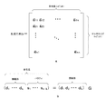
- FIG. 5 is a diagram illustrating an example of a generator matrix and a code word in the first embodiment.
- a in the same figure is a figure which shows an example of the production
- the number of rows in this generator matrix is k (k is an integer), and the number of columns is n (n is an integer greater than k).
- B in the same figure is an example of the calculation formula which calculates
- the data size of the information part is larger than the unit for encoding the user data, and the user data is stored together with other non-user data in this information part.
- a code word is generated by the product of the generator matrix G and the information part.
- This code word includes a k-bit information part and nk-bit parity. As described above, since the parity is generated by the product of the information part and the generation matrix, if even the information part is changed, the parity corresponding to the changed information part also changes.
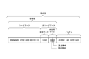
- FIG. 6 is a diagram illustrating an example of a data structure of a code word in the first embodiment.
- the code word is composed of a 4-byte information part and a 2-byte parity. This information part consists of 3 bytes of user data and 1 byte of non-user data.
- the non-user data includes 4-bit management data and 4-bit unused data. Due to the expandability of the memory system and the convenience of access units, the codeword is provided with non-user data having a certain amount of margin, and unused data is allocated to the remaining part other than the management data.
- the data size of each data in a code word is not limited to the size illustrated in FIG.
- the management data is data indicating conversion processing performed at the time of encoding the user data. For example, when the process of inverting the user data is performed as a conversion process, an inverted bit indicating whether the user data has been inverted is stored in the management data.
- unused data is non-user data that is not used for either user data or management data.
- This unused data consists of a 2-bit fixed area and a 2-bit variable area.
- the fixed area is an area in which fixed value data is stored. For example, the values of all bits in the fixed area are fixed to “0”.
- the variable area is an area in which any one of a plurality of values is stored. For example, any of binary numbers “00”, “01”, “10”, and “11” is selected by the encoding unit 320, and the data of the value is stored.
- selection value The value of data stored in this variable area.
- parity is stored in the 0th to 15th bits from the right end, and the 16th and 17th bits are used as a fixed area.
- the selection value is stored in the 18th and 19th bits from the right end, the management data is stored in the 20th to 23rd bits, and the user data is stored in the 24th and subsequent bits.
- the encoding part 320 can change the parity corresponding to the information part after the change by changing the selection value.
- the encoding unit 320 can generate four patterns of parity by changing the selection value to four patterns.
- FIG. 7 is a block diagram illustrating a configuration example of the encoding unit 320 according to the first embodiment.
- the encoding unit 320 includes a write buffer 321, a user data conversion unit 322, an ECC encoder 323, a candidate parity generation unit 330, a selection unit 340, and a write data output unit 324.
- the write buffer 321 holds user data from the host computer 100.
- the user data conversion unit 322 performs conversion processing on user data as necessary. For example, the user data conversion unit 322 performs a process of inverting at least some bits of user data. For example, a process of inverting the 1/3 or 2/3 bit of the user data or a process of inverting the whole is performed.
- the user data conversion unit 322 counts the number of “1” bits of user data before inversion.
- the number of bits of a specific value (for example, “1”) in data is referred to as “weight” of the data. As described above, the retention of the memory cell holding “0” is better than the memory cell holding “1”.
- the encoding unit 320 determines whether or not to invert depending on whether or not the number of bits of “1” (that is, the weight) is reduced, and determines a part to be inverted. By converting and writing user data so that the weight is reduced, the retention of the memory cell holding the user data can be improved.
- the user data conversion unit 322 generates physical data storing inverted bits indicating inverted parts of user data and unused data in which a predetermined selection value (for example, “00”) is set, and the user data Are supplied to the ECC encoder 323.
- a predetermined selection value for example, “00”
- the user data conversion unit 322 converts user data by inversion processing of at least a part of the user data. However, as long as the weight changes, it may be converted by processing other than inversion processing. For example, the user data conversion unit 322 may perform a process of calculating an XOR (exclusive OR) for each corresponding bit in a predetermined fixed pattern and user data.
- XOR exclusive OR
- the ECC encoder 323 encodes the information part.
- the ECC encoder 323 generates a code word including an information part and a parity from the generator polynomial G (x) of Expression 2 and the information part. Then, the ECC encoder 323 supplies the information part to the write data output part 324, and supplies the parity to the candidate parity generation part 330 as the candidate parity C0.
- the ECC encoder 323 is an example of a first candidate parity generation unit described in the claims.
- the candidate parity generation unit 330 generates a parity for detecting an error in the information unit in which a part of data is changed as a candidate parity.
- the candidate parity generation unit 330 generates a parity corresponding to an information unit in which a selection value (such as “01”) other than “00” is set for unused data as a candidate parity.
- the candidate parity generation unit 330 generates a candidate parity for each of the information part of the selection value “01”, the information part of the selection value “10”, and the information part of the selection value “11”. Let these candidate parities be C1, C2, and C3.
- the candidate parity generation unit 330 supplies the candidate parity C0 from the ECC encoder 323 and the candidate parities C1, C2, and C3 generated by the candidate parity generation unit 330 to the selection unit 340.
- the number of candidate parities generated by the candidate parity generation unit 330 may be one or more, and is not limited to three.
- the number of bits in the variable area in which the selection value is stored may be changed according to the number of candidate parities to be generated. For example, when a 3-bit variable area is provided, the ECC encoder 323 and the candidate parity generation unit 330 can generate a total of eight candidate parities.
- the selection unit 340 selects a parity that satisfies a predetermined condition among the candidate parities C0, C1, C2, and C3. For each candidate parity, the selection unit 340 counts and compares a set of weights composed of unused data corresponding to the candidate parity and the candidate parity. Then, the selection unit 340 selects the one having the smallest weight from the set of candidate parity and unused data. The selection unit 340 supplies the selected set of candidate parities as selection parity to the write data output unit 324 together with a selection value corresponding to the selection parity.
- the encoding unit 320 selects and writes candidate parity and unused data having the smallest number of bits (ie, weight) of “1”, thereby improving retention of memory cells that hold the data. be able to.
- the selection unit 340 counts the number of bits having a value of “1” as a “weight”, but may count the number of bits having a value of “0” as a weight.
- the write data output unit 324 outputs a code word composed of an information unit corresponding to the selected parity and the selected parity as write data.
- the write data output unit 324 updates the unused data in the information part with the selection value corresponding to the selected parity, and outputs a code word composed of the information part and the selected parity to the memory interface 317.
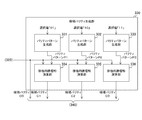
- FIG. 8 is a block diagram illustrating a configuration example of the candidate parity generation unit 330 according to the first embodiment.
- the candidate parity generation unit 330 includes parity pattern generation units 331, 332, and 333 and exclusive OR operation units 334, 335, and 336.
- the parity pattern generation unit 331 generates parity from an information unit in which a selection value “01” is set for unused data and all bits other than unused data are set to “0”.
- the parity is generated by, for example, the product of the information part and the generator polynomial G (x).
- the parity pattern generation unit 331 supplies the generated parity to the exclusive OR operation unit 334 as the parity pattern P1.
- the parity pattern generation unit 332 generates parity from an information unit in which a selection value “10” is set for unused data and “0” is set for all bits other than unused data.
- the parity pattern generation unit 332 supplies the generated parity to the exclusive OR operation unit 335 as the parity pattern P2.
- Parity pattern generation section 333 generates parity from an information section in which a selection value “11” is set for unused data and “0” is set for all bits other than unused data.
- the parity pattern generation unit 333 supplies the generated parity to the exclusive OR operation unit 336 as a parity pattern P3.
- the exclusive OR operation unit 334 calculates XOR (exclusive OR) for each corresponding bit in the candidate parity C0 and the parity pattern P1.
- the exclusive OR operation unit 334 supplies the operation result to the selection unit 340 as the candidate parity C1.
- the exclusive OR operation unit 334 is an example of a second candidate parity generation unit described in the claims.
- the exclusive OR calculator 335 calculates XOR for each corresponding bit in the candidate parity C0 and the parity pattern P2.
- the exclusive OR operation unit 335 supplies the operation result to the selection unit 340 as the candidate parity C2.
- the exclusive OR operation unit 335 is an example of a third candidate parity generation unit described in the claims.
- the exclusive OR operation unit 336 calculates XOR for each corresponding bit in the candidate parity C0 and the parity pattern P3.
- the exclusive OR operation unit 336 supplies the operation result to the selection unit 340 as the candidate parity C3.
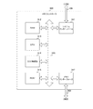
- FIG. 9 is a block diagram illustrating a configuration example of the selection unit 340 according to the first embodiment.
- the selection unit 340 includes weight counters 341, 342, 343 and 344, adders 346, 347 and 348, and a comparison unit 345.
- the weight counter 341 counts the number (weight) of “1” of the candidate parity C3.
- the weight counter 341 supplies the count value to the adder 346.
- the adder 346 adds the number of unused data weights (for example, “2”) corresponding to the candidate parity C3 to the count value of the weight of the candidate parity C3.
- the adder 346 supplies the count value CNT3 after the addition to the comparison unit 345.
- the weight counter 342 counts the weight of the candidate parity C2.
- the weight counter 342 supplies the count value to the adder 347.
- the adder 347 adds the number of unused data weights (for example, “1”) corresponding to the candidate parity C2 to the count value of the weight of the candidate parity C2.
- the adder 347 supplies the added count value CNT2 to the comparison unit 345.
- the weight counter 343 counts the weight of the candidate parity C1.
- the weight counter 343 supplies the count value to the adder 348.
- the adder 348 adds the number of unused data weights (for example, “1”) corresponding to the candidate parity C1 to the count value of the weight of the candidate parity C1.
- the adder 348 supplies the count value CNT1 after the addition to the comparison unit 345.
- the weight counter 343 and the adder 348 are an example of a second weight counter described in the claims.
- the weight counter 344 counts the weight of the candidate parity C0.
- the weight counter 344 supplies the count value CNT0 to the comparison unit 345.
- the weight counter 344 is an example of a first weight counter described in the claims.
- the comparison unit 345 selects a candidate parity having the smallest corresponding weight (CNT0 to CNT3) as a selection parity among the candidate parities C0 to C3.
- the comparison unit 345 supplies the selected selected parity and the selected value corresponding to the selected parity to the write data output unit 324.
- FIG. 10 is a block diagram illustrating a configuration example of the decoding unit 370 according to the first embodiment.
- the decoding unit 370 includes a read buffer 371, a user data reverse conversion unit 372, and an ECC decoder 373.
- the ECC decoder 373 reads the read data from the nonvolatile memory 400 and decodes the read data according to a decoding procedure corresponding to the encoding procedure of the encoding unit 320.
- the ECC decoder 373 supplies the decoded information part to the user data inverse conversion part 372.
- the user data reverse conversion unit 372 performs reverse conversion processing corresponding to the conversion processing of the encoding unit 320 on the user data in the information unit. For example, the user data reverse conversion unit 372 performs, as reverse conversion processing, processing that inverts at least a part of user data and restores the original data based on the inverted bit in the management data in the information unit. The user data reverse conversion unit 372 supplies the user data after the reverse conversion process to the read buffer 371.
- the read buffer 371 holds user data from the user data reverse conversion unit 372 and supplies it to the system interface 311 as correction data.
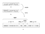
- FIG. 11 is a diagram illustrating an example of user data and codewords in the first embodiment.
- a shows an example of user data before inversion
- b in the figure shows an example of user data partially inverted.
- “*” indicates the bit position of the value “1”.
- the part surrounded by the dotted line b in FIG. 4 shows an inverted bit string. For example, 1 byte of 3 bytes of user data is inverted. Thereby, the weight is reduced as illustrated in FIG.
- C in FIG. 11 is a diagram illustrating an example of a code word in the first embodiment. Since the leftmost byte of user data is inverted, an inverted bit of “1” indicating that the leftmost part is inverted is set as the leftmost bit of the management data. In addition, a selection value “00” is set for unused data.
- the ECC encoder 323 generates an information part composed of the management data and unused data and the inverted user data, and generates a candidate parity C0 from the information part.
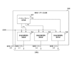
- FIG. 12 is a diagram illustrating an example of the information part and the candidate parity in the first embodiment.
- a indicates a code word composed of user data, unused data of the selected value “00”, and candidate parity C0.
- Candidate parity generator 330 sets selection values “01”, “10”, and “11”, and sets parity patterns P1, P2, and P3 from each of the information units in which all other bits are set to “0”. Generate.
- b indicates a code word including the parity pattern P1
- c in FIG. 12 indicates a code word including the parity pattern P2.
- d in the figure indicates a code word including the parity pattern P3. Then, the candidate parity generation unit 330 performs an XOR operation for each corresponding bit on the candidate parity C0 and the parity patterns P1, P2, and P3, and generates candidate parity C1, C2, and C3.
- e indicates a code word including the candidate parity C1
- f in FIG. 12 indicates a code word including the candidate parity C2.
- g in the figure indicates a code word including the candidate parity C3.
- a result of adding codewords becomes a codeword in the code. Therefore, the result of performing an XOR operation (in other words, addition) for each corresponding bit on the code word including the parity pattern P1 and the code word including the candidate parity C0 becomes a code word. For this reason, the error of the corresponding information part can be detected and corrected by the candidate parity C0 in the code word of the addition result. Therefore, the decoding unit 370 does not need to perform an XOR operation on the selected parity, and can perform decoding as it is.
- the candidate parity generation unit 330 then counts the weights in the candidate parities C0 to C3 and the corresponding selection value.
- “*” In FIG. 12 indicates the position of the counted bit. For example, the number (weight) of the candidate parity C0 and the selection value “00” “*” is “8” in decimal. Also. The weight of the candidate parity C1 and the selection value “01” is “8” in decimal number, and the weight of the candidate parity C2 and the selection value “10” is “5” in decimal number. The weight of the candidate parity C3 and the selection value “11” is “8” in decimal.
- the minimum value of these weights is “5”, and the corresponding candidate parity C2 is selected. Note that when there are two or more candidate parities having the smallest weight, any one of them is arbitrarily selected.
- the encoding unit 320 changes a part of the information unit (that is, unused data) to generate a plurality of candidate parities, and selects the parity with the smallest weight among them. select. For this reason, the weight of the memory cell to which parity and unused data are written becomes small. For example, in the example of FIG. 12, the weight can be reduced from “8” to “5”. Thereby, the retention of the memory cell can be improved.
- the candidate parities C1 to C3 are generated by the generation of the parity pattern and the XOR operation, it is not limited to this configuration.
- the encoding unit 320 may generate the candidate parity C1 or the like by the product of the information unit obtained by changing only unused data e to g in FIG. 12 and the generator polynomial G (x).
- the amount of calculation is smaller when generating the parity pattern and performing the XOR operation. For example, when a parity pattern is generated from an information part in which all bits other than unused data in the information part are set to “0”, since data other than unused data is “0”, user data is stored.
- the encoding unit 320 generates the candidate parity C1 and the like by generating a parity pattern and performing an XOR operation.
- the encoding unit 320 converts user data, it may encode the user data as it is without converting the user data. In this case, the decoding unit 370 performs only decoding without performing inverse transformation.
- the encoding unit 320 is provided in the memory system, the encoding unit 320 may be provided in a system other than the memory system as long as it is a system (communication system) that performs encoding. For example, in the case of a communication system that consumes less power when transmitting low-level bits than when transmitting high-level bits, the encoding unit 320 selects the parity with the smallest weight to consume power. Can be reduced.
- FIG. 13 is a block diagram illustrating a configuration example of the nonvolatile memory 400 according to the first embodiment.
- the nonvolatile memory 400 includes a data buffer 410, a memory cell array 420, a driver 430, an address decoder 440, a bus 450, a control interface 460, and a memory control unit 470.
- the data buffer 410 holds write data and read data in units of access under the control of the memory control unit 470.
- the memory cell array 420 includes a plurality of memory cells arranged in a matrix. As each memory cell, a nonvolatile memory element such as ReRAM is used.
- the driver 430 writes data to or reads data from the memory cell selected by the address decoder 440.
- the address decoder 440 analyzes an address designated by a command and selects a memory cell corresponding to the address.
- the bus 450 is a common path for the data buffer 410, the memory cell array 420, the address decoder 440, the memory control unit 470, and the control interface 460 to exchange data with each other.
- the control interface 460 is an interface for the memory controller 300 and the nonvolatile memory 400 to exchange data and commands with each other.
- the memory control unit 470 controls the driver 430 and the address decoder 440 to write or read data.
- the memory control unit 470 receives a control signal for instructing writing and write data
- the memory control unit 470 reads data written at an address designated by the control signal as pre-read data.
- the memory control unit 470 compares the write data and the pre-read data in bit units, and sets the bit that is “1” in the write data and “0” in the pre-read data to be rewritten.
- the memory control unit 470 rewrites those bits to be rewritten to “1”.
- the memory control unit 470 compares the write data with the pre-read data after the set processing in units of bits, and rewrites the bit of “0” in the write data and “1” in the pre-read data. And The memory control unit 470 rewrites those bits to be rewritten to “0”.
- the memory control unit 470 controls the address decoder 440 and the driver 430 to output read data to the memory controller 300.
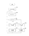
- FIG. 14 is a flowchart illustrating an example of the operation of the storage 200 according to the first embodiment. This operation starts, for example, when the host computer 100 instructs the storage 200 to be initialized.
- the nonvolatile memory 400 initializes the memory cell array 420 (step S901).
- the memory controller 300 decodes the command from the host computer 100 (step S902).
- the memory controller 300 determines whether or not the command is a write command (step S903).
- the command from the host computer 100 is either a write command or a read command.
- step S903 If it is a write command (step S903: Yes), the memory controller 300 executes controller side write processing (step S910). Then, the nonvolatile memory 400 executes NVRAM side write processing (step S930).
- step S903 if it is a read command (step S903: No), the memory controller 300 executes a controller-side read process (step S950). Then, the nonvolatile memory 400 reads the data and transfers it to the memory controller 300 (step S904). After step S930 or S904, the storage 200 returns to step S902.
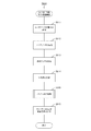
- FIG. 15 is a flowchart illustrating an example of the controller-side write process according to the first embodiment.
- the memory controller 300 counts the weight of the user data (step S911), and inverts at least a part of the user data based on the count value (step S912).
- the memory controller 300 stores the inversion flag in the management data (step S913), and encodes the information part including the user data after the inversion process into a code word including the information part and the candidate parity C0 (step S914).
- the memory controller 300 executes a parity selection process for selecting one of a plurality of candidate parities (step S920). Then, the memory controller 300 outputs write data including the selected parity and the corresponding information part to the nonvolatile memory 400 (step S915), and ends the controller side write process.
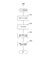
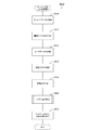
- FIG. 16 is a flowchart illustrating an example of parity selection processing in the first embodiment.
- the memory controller 300 generates a candidate parity for each selection value (step S921), and counts the weight for each candidate parity (step S922).
- the memory controller 300 selects a candidate parity with the smallest weight (step S923), and stores the selected parity and the corresponding selection value in the code word (step S924). After step S924, the memory controller 300 ends the parity selection process.
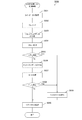
- FIG. 17 is a flowchart illustrating an example of the NVRAM side write process according to the first embodiment.
- the nonvolatile memory 400 acquires write data (step S931).
- the nonvolatile memory 400 pre-reads the data written at the write destination address (step S932).
- the nonvolatile memory 400 compares corresponding bits in the write data and the pre-read data, and generates reset mask data (step S933).
- This reset mask data indicates that bits that are “0” in the write data and “1” in the pre-read data are to be reset, and other bits are to be masked.
- the non-volatile memory 400 performs a process (reset process) of rewriting only the bit indicated to be reset by the reset mask data from “1” to “0” (step S934).
- the nonvolatile memory 400 reads the pre-read data after the reset process, and determines whether or not a verify error has occurred (step S935).
- step S935 the nonvolatile memory 400 compares the corresponding bits in the write data and the pre-read data after reset processing, and generates set mask data (step S935). S936).
- This set mask data indicates that bits that are “1” in the write data and “0” in the pre-read data are set, and that other bits are masked.
- the non-volatile memory 400 performs processing (set processing) of rewriting only the bits indicated to be set by the set mask data from “0” to “1” (step S937).
- the nonvolatile memory 400 reads the pre-read data after the set processing, and determines whether or not a verify error has occurred (step S938).
- step S935 When an error occurs in the reset process (step S935: Yes), or when an error occurs in the set process (step S938: Yes), the nonvolatile memory 400 notifies the host computer 100 of a write error (step S939). ). If no error has occurred in the set process (step S938: No), or after step S939, the nonvolatile memory 400 transfers the status to the memory controller 300 (step S940). After step S940, the nonvolatile memory 400 ends the NVRAM side write process.
- FIG. 18 is a flowchart illustrating an example of the controller-side read process according to the first embodiment.
- the memory controller 300 acquires the read data (step S951) and decrypts it (step S952).
- the memory controller 300 inverts the user data based on the management data (step S953).
- the memory controller 300 outputs the user data as correction data to the host computer 100 (step S954), and ends the controller-side read process.
- the encoding unit 320 generates a candidate parity by setting a plurality of different values in the variable region in the information unit, and the weight is the smallest among them. Therefore, the data retention characteristic of the memory cell can be improved.
- the candidate parity generation unit 330 generates a parity pattern by matrix calculation. However, as the codeword data size increases, the calculation amount may increase.
- the candidate parity generation unit 330 according to the modification of the first embodiment is different from the first embodiment in that the amount of calculation is reduced.
- FIG. 19 is a block diagram illustrating a configuration example of the candidate parity generation unit 330 according to the modification of the first embodiment.
- the candidate parity generation unit 330 of this modification is different from that of the first embodiment in that a parity pattern holding unit 337 is provided instead of the parity pattern generation units 331, 332, and 333.
- the parity pattern holding unit 337 holds parity patterns (P1, P2, P3, etc.) calculated in advance for each selected value. What are these parity patterns? It is read by each of the exclusive OR operation units 334, 335 and 336.
- the candidate parity generation unit 330 needs to perform a matrix operation to obtain a parity pattern in order to hold the parity pattern that has been calculated in advance. Disappear.
- the memory controller 300 selects the candidate parity having the smallest weight as the selected parity.
- the retention of the memory cell may not be sufficiently improved. For this reason, it is desirable to reduce the number of bits to be rewritten.
- the memory controller 300 of the second embodiment differs from the first embodiment in that the number of bits to be rewritten is reduced.
- FIG. 20 is a block diagram illustrating a functional configuration example of the memory controller 300 according to the second embodiment.
- the memory controller 300 according to the second embodiment is different from the first embodiment in that a command control unit 381 is provided instead of the command control unit 380.
- the command control unit 381 When the command control unit 381 receives a write command, the command control unit 381 generates a control signal for requesting writing and outputting pre-read data, and supplies the control signal to the nonvolatile memory 400. In accordance with this control signal, the memory controller 300 outputs pre-read data before write data is written to the memory controller 300.
- the encoding unit 320 compares the pre-read data with the code word in bit units, and generates write data that minimizes the number of bits to be rewritten.
- FIG. 21 is a block diagram illustrating a configuration example of the encoding unit 320 according to the second embodiment.
- the encoding unit 320 according to the second embodiment is different from the first embodiment in that a user data conversion unit 325 and a selection unit 350 are provided instead of the user data conversion unit 322 and the selection unit 340.
- the user data conversion unit 325 acquires a set of user data and management data in the pre-lead. Then, the user data conversion unit 325 counts the number of bits having different values from the corresponding bits in the pre-read data in the user data and management data before inversion. Based on the count value, the user data conversion unit 325 performs inversion processing so that the number of rewrite bits is minimized, and supplies an information unit including user data after the inversion processing to the ECC encoder 323.
- the selection unit 350 acquires a set including unused data and parity in the pre-read. Then, the user data conversion unit 325 counts the number of bits having different values from the corresponding bits in the pre-read data for each set of candidate parity and unused data. The user data conversion unit 325 selects a set of candidate parities with the smallest count value (that is, the number of bits to be rewritten).
- FIG. 22 is a block diagram illustrating a configuration example of the selection unit 350 according to the second embodiment.
- the selection unit 350 includes an unused data holding unit 351, exclusive OR operation units 352 to 355, rewrite bit number counters 356 to 359, and a comparison unit 345.
- the unused data holding unit 351 holds a plurality of unused data set with different selection values. These unused data are read by the exclusive OR operation units 352 to 355.
- the exclusive OR operation unit 352 performs an XOR operation for each bit corresponding to the parity and unused data in the pre-read data, the candidate parity C3, and the corresponding unused data. As unused data corresponding to the candidate parity C 3, “1100” is read from the unused data holding unit 351. The exclusive OR operation unit 352 supplies the operation result to the rewrite bit number counter 356.
- the exclusive OR operation unit 353 performs an XOR operation for each corresponding bit of the data in the pre-read data, the candidate parity C2, and the corresponding unused data “1000”.
- the exclusive OR operation unit 353 supplies the operation result to the rewrite bit number counter 357.
- the exclusive OR operation unit 354 performs an XOR operation for each corresponding bit of the data in the pre-read data, the candidate parity C1, and the corresponding unused data “0100”.
- the exclusive OR operation unit 354 supplies the operation result to the rewrite bit number counter 358.
- the exclusive OR operation unit 355 performs an XOR operation for each bit corresponding to the data in the pre-read data, the candidate parity C0, and the corresponding unused data “0000”.
- the exclusive OR operation unit 355 supplies the operation result to the rewrite bit number counter 359.
- the rewrite bit number counter 356 counts the number of “1” in the operation result of the exclusive OR operation unit 352 as the number of rewrite bits.
- the rewrite bit number counter 356 supplies the count value CNT3 to the comparison unit 345.
- the rewrite bit number counter 357 counts the number of “1” as the number of rewrite bits in the operation result of the exclusive OR operation unit 353.
- the rewrite bit number counter 357 supplies the count value CNT2 to the comparison unit 345.
- the rewrite bit number counter 358 counts the number of “1” in the operation result of the exclusive OR operation unit 354 as the rewrite bit number.
- the rewrite bit number counter 358 supplies the count value CNT1 to the comparison unit 345.
- the rewrite bit number counter 359 counts the number of “1” in the operation result of the exclusive OR operation unit 355 as the rewrite bit number.
- the rewrite bit number counter 359 supplies the count value CNT0 to the comparison unit 345.
- the configuration of the comparison unit 345 of the second embodiment is the same as that of the first embodiment.
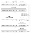
- FIG. 23 is a diagram illustrating an example of an information part and a candidate parity in the second embodiment.
- a indicates a code word composed of user data, unused data of the selected value “00”, and candidate parity C0.
- B in the figure shows an example of pre-read data.
- c in FIG. 22 indicates a code word including the candidate parity C1
- d in FIG. 22 indicates a code word including the candidate parity C2.
- e in the figure indicates a code word including the candidate parity C3.
- the candidate parity generation unit 330 compares the parity and unused data in the pre-read data with the candidate parity and corresponding unused data in bit units. From this comparison result, the candidate parity generation unit 330 calculates the number of rewrite bits for each candidate parity.
- “*” indicates the position of the rewrite bit.
- the number of rewrite bits is “12” in decimal.
- the number of rewrite bits is “9” in decimal
- candidate parity C2 and unused data “1000” the number of rewrite bits is “13” in decimal.
- the candidate parity C3 and the unused data “1100” the number of rewrite bits is “12” in decimal.
- the candidate parity C2 with the smallest number of rewrite bits is selected. Thereby, the number of rewrite bits of the memory cell is reduced, and the retention of the memory cell can be improved.
- FIG. 24 is a flowchart illustrating an example of a controller-side write process according to the second embodiment.
- the controller-side write process of the second embodiment differs from the first embodiment in that steps S916 and S917 are executed instead of step S911.
- Memory controller 300 acquires pre-read data (step S916), and counts the number of rewrite bits for the user data before inversion (step S917). After step S917, the memory controller 300 executes step S912 and subsequent steps.
- FIG. 25 is a flowchart illustrating an example of parity selection processing according to the second embodiment.
- the parity selection processing of the second embodiment is different from the first embodiment in that steps S925 and S926 are executed instead of steps S922 and S923.
- the memory controller 300 generates candidate parity (step S921), and counts the number of rewrite bits for each candidate parity (step S925). The memory controller 300 selects a candidate parity that minimizes the number of rewrite bits (step S926), and executes step S924.
- the encoding unit 320 selects the parity that minimizes the number of rewrite bits among the candidate parities, and therefore reduces the number of rewrite bits of the memory cell. Data retention characteristics of the memory cell can be improved.
- FIG. 26 is a diagram illustrating an example of a data structure of a code word in the third embodiment.
- the gray area in the figure indicates a fixed area, and the shaded area indicates a variable area.
- a in the same figure is a figure which shows an example of the data structure of the codeword which changed the position of the variable area in 3rd Embodiment.
- This code word differs from the first embodiment in that the position of the variable area and the position of the fixed area are interchanged. That is, they are arranged in the order of parity, variable area, fixed area, management data, and user data from the right end of the codeword.
- variable area and the fixed area are each divided into two, and in order from the right end of the codeword, the parity, a part of the fixed area, a part of the variable area, the remaining fixed area, the remaining variable area, the management data, and the user Arranged in order of data.
- C in FIG. 26 is a diagram illustrating an example of a data structure of a codeword in which the position of the non-user data area in the third embodiment is changed. For example, they are arranged in the order of parity, user data, and non-user data from the right end of the codeword.
- D in FIG. 26 is a diagram illustrating an example of a data structure of a codeword in which user data is distributed according to the third embodiment.
- the user data is divided into two, and arranged from the right end of the codeword in the order of parity, part of user data, non-user data, and remaining user data.
- E in FIG. 26 is a diagram illustrating an example of a data structure of a codeword in which user data and non-user data are distributed in the third embodiment.
- user data and non-user data are divided into two, and in order from the right end of the codeword, parity, a part of user data, a part of non-user data, the rest of user data, and the rest of non-user data Arranged in order.
- FIG. 26f is a diagram illustrating an example of a data structure of a codeword in which non-user data is distributed and variable regions and fixed regions are distributed in the third embodiment.
- the non-user data is divided into two, and the variable area and the fixed area are also divided into two.
- parity, part of the fixed area, part of the variable area, user data, the rest of the fixed area, the rest of the variable area, and management data are arranged in this order from the right end of the codeword.
- the data structure of the codeword is not limited to the structure illustrated in FIG.
- user data or the like may be divided into three or more, and a variable area may be arranged at the left end of the code word.
- the weight in the parity can be changed by changing the position of the variable area in which the selection value is stored.
- the selected value is arranged at the 18th and 19th bits from the right end and all other bits are set to “0”, and a generator polynomial G (x) It is assumed that a parity pattern has been generated.
- Parity pattern P1 0000000 10110100 with selected value “01”
- the number of bits (weight) of “1” is larger in the parity patterns P1 ′, P2 ′, and P3 ′ than in the above-described parity patterns P1, P2, and P3.
- the arrangement of a in FIG. Since the position of the optimal variable area varies depending on the data size of the information part, the generator polynomial, and the type of code, the parity is generated by changing the position of the variable area in several ways, and the optimal position is obtained by comparing them. Is required.
- the weight is reduced and the data retention characteristic is improved. be able to.
- the candidate parity generation unit 330 generates three parity patterns by the parity pattern generation units 331, 332, and 333. That is, the same number of parity pattern generation units as the parity patterns are provided. However, as the number of parity patterns increases, the number of parity pattern generation units increases, which may increase the amount of computation and the circuit scale.
- the candidate parity generation unit 330 according to the fourth embodiment is different from the first embodiment in that the number of circuits that generate parity patterns is reduced.
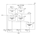
- FIG. 27 is a block diagram illustrating a configuration example of the candidate parity generation unit 330 according to the fourth embodiment.
- the candidate parity generation unit 330 according to the fourth embodiment differs from the first embodiment in that the parity pattern generation unit 333 is not provided.
- the exclusive OR operation unit 336 of the fourth embodiment differs from the first embodiment in that XOR operation is performed for each bit corresponding to the candidate parity C1 and the parity pattern P2.
- the candidate parity C3 is obtained by this XOR operation. This is because the addition of the code word including the candidate parity C1 and the code word including the parity pattern P2 results in a code word including the candidate parity C3.
- the exclusive OR operation unit 336 is an example of a fourth candidate parity generation unit described in the claims.
- the candidate parity generation unit 330 generates the parity pattern P3 because the candidate parity P3 is generated by the XOR operation of the candidate parity C1 and the parity pattern P2. Circuits can be reduced.
- the memory controller 300 selects the candidate parity having the smallest weight as the selected parity.
- the power consumption during writing may increase. For this reason, it is desirable to reduce the number of bits to be continuously rewritten.
- the memory controller 300 according to the fifth embodiment is different from the first embodiment in that the number of bits to be continuously rewritten is reduced.
- FIG. 28 is a block diagram illustrating a configuration example of the selection unit 350 according to the fifth embodiment.
- the selection unit 350 includes an unused data holding unit 351, exclusive OR operation units 352 to 355, a longest run counter 361 to 364, and a comparison unit 345.
- the configurations of the unused data holding unit 351 and the exclusive OR operation units 352 to 355 are the same as those in the second embodiment.
- the configuration of the unused data holding unit 351 of the fifth embodiment is the same as that of the second embodiment, and the configuration of the comparison unit 345 of the fifth embodiment is the same as that of the first embodiment. It is the same.
- the longest run counter 361 counts the length of the run in the calculation result of the exclusive OR calculation unit 352, and obtains the maximum value as the length of the longest run.
- “run” indicates a set of bits having a specific value (for example, “1”).
- the length of the longest run indicates the maximum number of bits that can be rewritten continuously.
- the longest run counter 361 supplies the length of the longest run to the comparison unit 345 as CNT3.
- the longest run counter 362 obtains the length of the longest run in the operation result of the exclusive OR operation unit 353.
- the longest run counter 362 supplies the obtained length to the comparison unit 345 as CNT2.
- the longest run counter 363 obtains the length of the longest run in the operation result of the exclusive OR operation unit 354. The longest run counter 363 supplies the obtained length to the comparison unit 345 as CNT1.
- the longest run counter 364 obtains the length of the longest run in the operation result of the exclusive OR operation unit 355.
- the longest run counter 364 supplies the obtained length to the comparison unit 345 as CNT0.
- FIG. 29 is a diagram illustrating an example of an information part and a candidate parity in the fifth embodiment.
- a indicates a code word composed of user data, unused data of the selected value “00”, and candidate parity C0.
- B in the figure shows an example of pre-read data.
- c in FIG. 29 indicates a code word including the candidate parity C1
- d in FIG. 29 indicates a code word including the candidate parity C2.
- e in the figure indicates a code word including the candidate parity C3.
- the candidate parity generation unit 330 compares the parity and unused data in the pre-read data with the candidate parity and corresponding unused data in bit units.
- the candidate parity generation unit 330 obtains the number of bits to be continuously rewritten (that is, the length of the longest run) for each candidate parity.
- “*” indicates the position of the rewrite bit.
- the portion surrounded by a dotted line indicates the longest run.
- the longest run length For example, with the candidate parity C0 and unused data “0000”, the length of the longest run is “6” in decimal.
- the longest run length is “3” in decimal
- candidate parity C2 and unused data “1000” the longest run length is “5” in decimal. It becomes.
- the length of the longest run is “3” in decimal.
- one of the candidate parities C1 and C3 having the shortest run length is selected.
- the encoding unit 320 can improve the power consumption and data retention characteristics of the nonvolatile memory 400 by selecting the candidate parity having the shortest longest run length.
- FIG. 30 is a flowchart illustrating an example of parity selection processing according to the fifth embodiment.
- the parity selection process of the second embodiment is different from the first embodiment in that steps S927 and S928 are executed instead of steps S922 and S923.
- the memory controller 300 generates candidate parity (step S921), and counts the length of the longest run for each candidate parity (step S927).
- the memory controller 300 selects a candidate parity that minimizes the length of the longest run (step S928), and executes step S924. Note that the controller-side write processing of the fifth embodiment is the same as that of the second embodiment.
- the encoding unit 320 selects the parity that minimizes the number of bits to be continuously rewritten, and thus the nonvolatile memory at the time of writing to the memory cell 400 power consumption can be reduced.
- the processing procedure described in the above embodiment may be regarded as a method having a series of these procedures, and a program for causing a computer to execute these series of procedures or a recording medium storing the program. You may catch it.
- a recording medium for example, a CD (Compact Disc), an MD (MiniDisc), a DVD (Digital Versatile Disc), a memory card, a Blu-ray disc (Blu-ray (registered trademark) Disc), or the like can be used.
- this technique can also take the following structures.
- a second candidate parity generation unit that generates, as a second candidate parity, a parity for detecting an error in the information unit in which a value different from the predetermined value is set in the predetermined variable region;
- a selection unit that selects, as the selected parity, a parity that satisfies a predetermined condition among the first and second candidate parities;
- An encoding apparatus comprising: an output unit that outputs a codeword including the information unit corresponding to the selected parity and the selected parity.
- the encoding device (2) The encoding device according to (1), wherein the information unit includes user data input to the first candidate parity generation unit and unused data including the predetermined variable region.
- the selection unit A first weight counter that counts the number of bits of a specific value as a weight in the first candidate parity and the unused data corresponding to the first candidate parity;
- a second weight counter that counts the number of bits of the specific value as a weight in the second candidate parity and the unused data corresponding to the second candidate parity;
- the encoding device further comprising: a comparison unit that compares the count values of the first and second weight counters and selects a parity that satisfies the predetermined condition based on the comparison result.
- (4) further comprising a control unit for reading data written in the memory cell as pre-read data;
- the selection unit counts the number of bits different in value from the pre-read data as the number of rewrite bits in the first candidate parity and the unused data corresponding to the first candidate parity.
- a counter A second rewrite bit number counter that counts, as the rewrite bit number, the number of bits different in value from the pre-read data in the second candidate parity and the unused data corresponding to the second candidate parity;
- the description (2) further comprising: a comparison unit that compares the number of rewrite bits counted by each of the first and second rewrite bit number counters and selects a parity that satisfies the predetermined condition based on the comparison result.
- Encoding device The description (2), further comprising: a comparison unit that compares the number of rewrite bits counted by each of the first and second rewrite bit number counters and selects a parity that satisfies the predetermined condition based on
- It further comprises a control unit that reads data written in the memory cell as pre-read data, The selection unit counts the number of consecutive bits having different values from the pre-read data in the first candidate parity and the unused data corresponding to the first candidate parity, and calculates the maximum value of the count value.
- a first longest run counter that calculates as the length of the longest run;
- the selection unit counts the number of consecutive bits having different values from the pre-read data in the second candidate parity and the unused data corresponding to the second candidate parity, and calculates the maximum value of the count value
- a second longest run counter for determining the longest run length as
- a comparison unit that compares the lengths of the longest runs obtained by the first and second longest run number counters and selects a parity that satisfies the predetermined condition based on the comparison result (2).
- (6) The encoding device according to any one of (2) to (5), wherein the unused data is arranged between the user data and the selected parity in the codeword.
- the encoding device according to any one of (2) to (5), wherein the user data is arranged between the unused data and the selected parity in the codeword.
- the encoding device according to any one of (2) to (5), wherein the user data is distributed and arranged in a plurality of regions in the codeword.
- the encoding device according to any one of (2) to (5), wherein the unused data in the codeword is distributed and arranged in a plurality of regions.
- the unused data includes the variable area and a fixed area whose value is not changed,
- the encoding device according to any one of (2) to (9), wherein the second candidate parity generation unit generates the second candidate parity corresponding to the information unit in which the value of the variable region is changed.
- the encoding device (11) The encoding device according to (10), wherein the variable areas in the codeword are distributed and arranged in a plurality of areas. (12) The encoding device according to (10) or (11), wherein in the codeword, the fixed area is distributed in a plurality of areas. (13) The first candidate parity generation unit generates the first candidate parity from the information unit, The second candidate parity generation unit generates the second candidate parity by a logical operation of the first candidate parity and a first parity pattern, according to any one of (1) to (12). Encoding device.
- a third candidate parity generation unit that generates a third candidate parity by a logical operation of a second parity pattern and the first candidate parity
- a fourth candidate parity generation unit that generates a fourth candidate parity by a logical operation of the second parity pattern and the second candidate parity
- a first candidate parity generation unit that performs a conversion process for converting the number of bits of a specific value in user data and converts the user data after the conversion process or the user data before the conversion process to the first candidate parity generation unit Further comprising a user data converter for outputting to The encoding according to any one of (1) to (14), wherein the first candidate parity generation unit generates the first candidate parity from the first information unit including the output user data. apparatus.
- a first candidate parity generation unit that generates, as a first candidate parity, a parity for detecting an error in an information unit in which a predetermined value is set in a predetermined variable area
- a second candidate parity generation unit that generates, as a second candidate parity, a parity for detecting an error in the information unit in which a value different from the predetermined value is set in the predetermined variable region
- a selection unit that selects, as the selected parity, a parity that satisfies a predetermined condition among the first and second candidate parities
- An output unit that outputs a code word composed of the information unit corresponding to the selected parity and the selected parity to a memory cell as write data
- a memory controller comprising: a read unit that reads read data from the memory cell and decodes the read data.
- a first candidate parity generation unit that generates, as a first candidate parity, a parity for detecting an error in an information unit in which a predetermined value is set in a predetermined variable region
- a second candidate parity generation unit that generates, as a second candidate parity, a parity for detecting an error in the information unit in which a value different from the predetermined value is set in the predetermined variable region
- a selection unit that selects, as the selected parity, a parity that satisfies a predetermined condition among the first and second candidate parities
- An output unit that outputs a codeword composed of the information unit corresponding to the selected parity and the selected parity as a transmission word
- a communication system comprising: a decoding unit that receives and decodes a reception word corresponding to the transmission word.
- a first candidate parity generation procedure for generating, as a first candidate parity, a parity for detecting an error in an information part in which a predetermined value is set in a predetermined variable area
- a second candidate parity generation procedure for generating, as a second candidate parity, a parity for detecting an error in the information unit in which a value different from the predetermined value is set in the predetermined variable region
- a selection procedure for selecting, as a selected parity, a parity that satisfies a predetermined condition among the first and second candidate parities
- An encoding method comprising: an output procedure for outputting a codeword composed of the information section corresponding to the selected parity and the selected parity.
Landscapes
- Engineering & Computer Science (AREA)
- Theoretical Computer Science (AREA)
- Physics & Mathematics (AREA)
- Probability & Statistics with Applications (AREA)
- General Physics & Mathematics (AREA)
- General Engineering & Computer Science (AREA)
- Quality & Reliability (AREA)
- Techniques For Improving Reliability Of Storages (AREA)
- Error Detection And Correction (AREA)
- For Increasing The Reliability Of Semiconductor Memories (AREA)
- Read Only Memory (AREA)
- Mathematical Physics (AREA)
- Algebra (AREA)
- Pure & Applied Mathematics (AREA)
Abstract
L'invention améliore les caractéristiques de conservation de données des cellules de mémoire d'un système de mémoire dans lequel des données sont codées puis écrites dans les cellules de mémoire. Une partie de génération de première parité candidate génère, en tant que première parité candidate, une parité utilisée pour détecter une erreur d'une partie d'informations dans laquelle une valeur prédéterminée est définie dans une zone variable prédéterminée. Une partie de génération de seconde parité candidate génère, en tant que seconde parité candidate, une parité utilisée pour détecter une erreur de la partie d'informations dans laquelle une valeur différente de la valeur prédéterminée est définie dans la zone variable prédéterminée. Une partie de sélection sélectionne, en tant que parité sélectionnée, une parité qui remplit une condition prédéterminée parmi les première et seconde parités candidates. Une partie de sortie génère un mot de code comprenant la partie d'informations correspondant à la parité sélectionnée ainsi que ladite parité sélectionnée.
Priority Applications (1)
| Application Number | Priority Date | Filing Date | Title |
|---|---|---|---|
| US15/736,079 US10481971B2 (en) | 2015-07-24 | 2016-04-15 | Encoding device, memory controller, communication system, and encoding method |
Applications Claiming Priority (2)
| Application Number | Priority Date | Filing Date | Title |
|---|---|---|---|
| JP2015-146671 | 2015-07-24 | ||
| JP2015146671A JP6657634B2 (ja) | 2015-07-24 | 2015-07-24 | 符号化装置、メモリシステム、通信システムおよび符号化方法 |
Publications (1)
| Publication Number | Publication Date |
|---|---|
| WO2017018008A1 true WO2017018008A1 (fr) | 2017-02-02 |
Family
ID=57884327
Family Applications (1)
| Application Number | Title | Priority Date | Filing Date |
|---|---|---|---|
| PCT/JP2016/062159 Ceased WO2017018008A1 (fr) | 2015-07-24 | 2016-04-15 | Dispositif de codage, contrôleur de mémoire, système de communication et procédé de codage |
Country Status (3)
| Country | Link |
|---|---|
| US (1) | US10481971B2 (fr) |
| JP (1) | JP6657634B2 (fr) |
| WO (1) | WO2017018008A1 (fr) |
Cited By (3)
| Publication number | Priority date | Publication date | Assignee | Title |
|---|---|---|---|---|
| WO2019126746A1 (fr) | 2017-12-22 | 2019-06-27 | Micron Technology, Inc. | Techniques de lecture de cellule de mémoire auto-référencées |
| US11282574B2 (en) | 2017-12-22 | 2022-03-22 | Micron Technology, Inc. | Auto-referenced memory cell read techniques |
| CN115796123A (zh) * | 2022-12-20 | 2023-03-14 | 四川启睿克科技有限公司 | 一种实现灵活配置生成编号和编号安全的方法 |
Families Citing this family (5)
| Publication number | Priority date | Publication date | Assignee | Title |
|---|---|---|---|---|
| KR20190074890A (ko) * | 2017-12-20 | 2019-06-28 | 에스케이하이닉스 주식회사 | 메모리 컨트롤러 및 그 동작 방법 |
| US11018694B2 (en) * | 2019-06-10 | 2021-05-25 | Hewlett Packard Enterprise Development Lp | Fast cyclic redundancy check code generation |
| US10944422B1 (en) * | 2019-09-23 | 2021-03-09 | Advanced Micro Devices, Inc. | Entropy agnostic data encoding and decoding |
| WO2022185089A1 (fr) * | 2021-03-02 | 2022-09-09 | Micron Technology, Inc. | Procédés et systèmes de gestion de mémoire avec protection ecc dynamique |
| FR3152078B1 (fr) * | 2023-08-09 | 2025-07-18 | St Microelectronics Int Nv | Système mémoire |
Citations (6)
| Publication number | Priority date | Publication date | Assignee | Title |
|---|---|---|---|---|
| JPH08335396A (ja) * | 1995-06-08 | 1996-12-17 | Sony Corp | 半導体不揮発性記憶装置 |
| JP2004164634A (ja) * | 2002-10-28 | 2004-06-10 | Sandisk Corp | 不揮発性メモリシステム内のエラー訂正コードのためのハイブリッド実装 |
| JP2011508358A (ja) * | 2007-12-27 | 2011-03-10 | インディリンクス カンパニー., リミテッド. | 摩耗度をビットレベルで平準化するフラッシュメモリ装置およびフラッシュメモリプログラミング方法 |
| JP2011526398A (ja) * | 2008-07-02 | 2011-10-06 | モサイド・テクノロジーズ・インコーポレーテッド | 極性制御部を有するセル当たり複数ビット(mbc)不揮発性メモリ装置およびメモリシステムとその書込み方法 |
| US20130019142A1 (en) * | 2011-07-12 | 2013-01-17 | Phison Electronics Corp. | Memory storage device, memory controller thereof, and method for programming data thereof |
| JP2013542533A (ja) * | 2010-10-27 | 2013-11-21 | エルエスアイ コーポレーション | フラッシュメモリベースのデータ記憶のための順応ecc技術 |
Family Cites Families (7)
| Publication number | Priority date | Publication date | Assignee | Title |
|---|---|---|---|---|
| JPH0795096A (ja) * | 1993-09-20 | 1995-04-07 | Fujitsu Ltd | プログラマブル並列crc生成装置 |
| JP4711660B2 (ja) * | 2004-11-10 | 2011-06-29 | 日本ビクター株式会社 | 記録装置および記録媒体 |
| CN103280239B (zh) * | 2006-05-12 | 2016-04-06 | 苹果公司 | 存储设备中的失真估计和消除 |
| JP4925301B2 (ja) * | 2007-02-07 | 2012-04-25 | 株式会社メガチップス | 半導体メモリシステム |
| JP5942781B2 (ja) | 2012-04-16 | 2016-06-29 | ソニー株式会社 | 記憶制御装置、メモリシステム、情報処理システム、および、記憶制御方法 |
| KR101997794B1 (ko) * | 2012-12-11 | 2019-07-09 | 삼성전자주식회사 | 메모리 제어기 및 그것을 포함한 메모리 시스템 |
| KR102133209B1 (ko) * | 2013-12-13 | 2020-07-14 | 에스케이하이닉스 주식회사 | 데이터 복호화 장치 및 데이터 복호화 방법 |
-
2015
- 2015-07-24 JP JP2015146671A patent/JP6657634B2/ja not_active Expired - Fee Related
-
2016
- 2016-04-15 WO PCT/JP2016/062159 patent/WO2017018008A1/fr not_active Ceased
- 2016-04-15 US US15/736,079 patent/US10481971B2/en active Active
Patent Citations (6)
| Publication number | Priority date | Publication date | Assignee | Title |
|---|---|---|---|---|
| JPH08335396A (ja) * | 1995-06-08 | 1996-12-17 | Sony Corp | 半導体不揮発性記憶装置 |
| JP2004164634A (ja) * | 2002-10-28 | 2004-06-10 | Sandisk Corp | 不揮発性メモリシステム内のエラー訂正コードのためのハイブリッド実装 |
| JP2011508358A (ja) * | 2007-12-27 | 2011-03-10 | インディリンクス カンパニー., リミテッド. | 摩耗度をビットレベルで平準化するフラッシュメモリ装置およびフラッシュメモリプログラミング方法 |
| JP2011526398A (ja) * | 2008-07-02 | 2011-10-06 | モサイド・テクノロジーズ・インコーポレーテッド | 極性制御部を有するセル当たり複数ビット(mbc)不揮発性メモリ装置およびメモリシステムとその書込み方法 |
| JP2013542533A (ja) * | 2010-10-27 | 2013-11-21 | エルエスアイ コーポレーション | フラッシュメモリベースのデータ記憶のための順応ecc技術 |
| US20130019142A1 (en) * | 2011-07-12 | 2013-01-17 | Phison Electronics Corp. | Memory storage device, memory controller thereof, and method for programming data thereof |
Cited By (11)
| Publication number | Priority date | Publication date | Assignee | Title |
|---|---|---|---|---|
| WO2019126746A1 (fr) | 2017-12-22 | 2019-06-27 | Micron Technology, Inc. | Techniques de lecture de cellule de mémoire auto-référencées |
| CN111480200A (zh) * | 2017-12-22 | 2020-07-31 | 美光科技公司 | 自动参考存储器单元读取技术 |
| EP3729429A4 (fr) * | 2017-12-22 | 2021-07-28 | Micron Technology, Inc. | Techniques de lecture de cellule de mémoire auto-référencées |
| US11282571B2 (en) | 2017-12-22 | 2022-03-22 | Micron Technology, Inc. | Auto-referenced memory cell read techniques |
| US11282574B2 (en) | 2017-12-22 | 2022-03-22 | Micron Technology, Inc. | Auto-referenced memory cell read techniques |
| CN111480200B (zh) * | 2017-12-22 | 2022-08-23 | 美光科技公司 | 自动参考存储器单元读取的方法和存储器设备 |
| CN115527580A (zh) * | 2017-12-22 | 2022-12-27 | 美光科技公司 | 自动参考存储器单元读取的方法和存储器设备 |
| US12009028B2 (en) | 2017-12-22 | 2024-06-11 | Micron Technology, Inc. | Auto-referenced memory cell read techniques |
| US12277969B2 (en) | 2017-12-22 | 2025-04-15 | Micron Technology, Inc. | Auto-referenced memory cell read techniques |
| EP4576095A3 (fr) * | 2017-12-22 | 2025-08-27 | Micron Technology, Inc. | Techniques de lecture de cellule de mémoire autoréférencée |
| CN115796123A (zh) * | 2022-12-20 | 2023-03-14 | 四川启睿克科技有限公司 | 一种实现灵活配置生成编号和编号安全的方法 |
Also Published As
| Publication number | Publication date |
|---|---|
| JP6657634B2 (ja) | 2020-03-04 |
| JP2017027440A (ja) | 2017-02-02 |
| US10481971B2 (en) | 2019-11-19 |
| US20180143871A1 (en) | 2018-05-24 |
Similar Documents
| Publication | Publication Date | Title |
|---|---|---|
| JP6657634B2 (ja) | 符号化装置、メモリシステム、通信システムおよび符号化方法 | |
| US20220245023A1 (en) | Detection and correction of data bit errors using error correction codes | |
| JP4988731B2 (ja) | フラッシュエラー訂正 | |
| JP6540703B2 (ja) | メモリコントローラおよびメモリコントローラの制御方法 | |
| JP5723967B2 (ja) | ソリッド・ステート・ストレージ・デバイスのsレベル・ストレージに入力データを記録するための方法、エンコーダ装置、およびソリッド・ステート・ストレージ・デバイス | |
| KR102226607B1 (ko) | 저장 디바이스를 위한 계단 코드 인코딩 및 디코딩을 위한 장치 및 방법 | |
| CN107077430B (zh) | 存储器控制器、存储器系统以及存储器控制器控制方法 | |
| JP2013524609A5 (fr) | ||
| KR102275717B1 (ko) | 플래시 메모리 시스템 및 그의 동작 방법 | |
| JP2010237822A (ja) | メモリコントローラおよび半導体記憶装置 | |
| US10498364B2 (en) | Error correction circuits and memory controllers including the same | |
| KR102754268B1 (ko) | 로직 연산을 공유하는 에러정정코드 디코더 및 이를 포함하는 메모리 컨트롤러와, 로직 연산을 공유할 수 있는 에러정정코드 디코딩 방법 | |
| KR102783025B1 (ko) | 에러 정정 코드 디코더, 이를 포함하는 메모리 컨트롤러, 및 에러 정정 코드 디코팅 방법 | |
| US9960788B2 (en) | Memory controller, semiconductor memory device, and control method for semiconductor memory device | |
| US10970166B2 (en) | Memory system and method of controlling non-volatile memory | |
| US10289348B2 (en) | Tapered variable node memory | |
| KR101355988B1 (ko) | 연접 비씨에이치 부호, 복호 및 다계층 복호 회로 및 방법, 이를 이용한 플래쉬 메모리 장치의 오류 정정 회로 및 플래쉬 메모리 장치 | |
| US8819331B2 (en) | Memory system and memory controller | |
| JP2026017720A (ja) | メモリシステムおよび制御方法 | |
| KR20250065088A (ko) | 3-비트 에러 검출을 지원하는 메모리 장치, 그것을 갖는 메모리 시스템, 및 그것의 동작 방법 | |
| JP5492329B2 (ja) | メモリアクセス装置 | |
| JP2011029857A (ja) | フラッシュファイルシステムの誤り検出訂正機能 | |
| JP2013201479A (ja) | 符号化装置、記憶装置および符号化方法 |
Legal Events
| Date | Code | Title | Description |
|---|---|---|---|
| 121 | Ep: the epo has been informed by wipo that ep was designated in this application |
Ref document number: 16830113 Country of ref document: EP Kind code of ref document: A1 |
|
| WWE | Wipo information: entry into national phase |
Ref document number: 15736079 Country of ref document: US |
|
| NENP | Non-entry into the national phase |
Ref country code: DE |
|
| 122 | Ep: pct application non-entry in european phase |
Ref document number: 16830113 Country of ref document: EP Kind code of ref document: A1 |