WO2017018062A1 - Dispositif d'observation de vapeur d'eau - Google Patents
Dispositif d'observation de vapeur d'eau Download PDFInfo
- Publication number
- WO2017018062A1 WO2017018062A1 PCT/JP2016/066985 JP2016066985W WO2017018062A1 WO 2017018062 A1 WO2017018062 A1 WO 2017018062A1 JP 2016066985 W JP2016066985 W JP 2016066985W WO 2017018062 A1 WO2017018062 A1 WO 2017018062A1
- Authority
- WO
- WIPO (PCT)
- Prior art keywords
- water vapor
- wave
- amount
- unit
- transmission
- Prior art date
- Legal status (The legal status is an assumption and is not a legal conclusion. Google has not performed a legal analysis and makes no representation as to the accuracy of the status listed.)
- Ceased
Links
Images








Classifications
-
- G—PHYSICS
- G01—MEASURING; TESTING
- G01N—INVESTIGATING OR ANALYSING MATERIALS BY DETERMINING THEIR CHEMICAL OR PHYSICAL PROPERTIES
- G01N22/00—Investigating or analysing materials by the use of microwaves or radio waves, i.e. electromagnetic waves with a wavelength of one millimetre or more
- G01N22/04—Investigating moisture content
-
- G—PHYSICS
- G01—MEASURING; TESTING
- G01S—RADIO DIRECTION-FINDING; RADIO NAVIGATION; DETERMINING DISTANCE OR VELOCITY BY USE OF RADIO WAVES; LOCATING OR PRESENCE-DETECTING BY USE OF THE REFLECTION OR RERADIATION OF RADIO WAVES; ANALOGOUS ARRANGEMENTS USING OTHER WAVES
- G01S13/00—Systems using the reflection or reradiation of radio waves, e.g. radar systems; Analogous systems using reflection or reradiation of waves whose nature or wavelength is irrelevant or unspecified
- G01S13/88—Radar or analogous systems specially adapted for specific applications
- G01S13/95—Radar or analogous systems specially adapted for specific applications for meteorological use
-
- G—PHYSICS
- G01—MEASURING; TESTING
- G01S—RADIO DIRECTION-FINDING; RADIO NAVIGATION; DETERMINING DISTANCE OR VELOCITY BY USE OF RADIO WAVES; LOCATING OR PRESENCE-DETECTING BY USE OF THE REFLECTION OR RERADIATION OF RADIO WAVES; ANALOGOUS ARRANGEMENTS USING OTHER WAVES
- G01S13/00—Systems using the reflection or reradiation of radio waves, e.g. radar systems; Analogous systems using reflection or reradiation of waves whose nature or wavelength is irrelevant or unspecified
- G01S13/88—Radar or analogous systems specially adapted for specific applications
- G01S13/95—Radar or analogous systems specially adapted for specific applications for meteorological use
- G01S13/951—Radar or analogous systems specially adapted for specific applications for meteorological use ground based
-
- G—PHYSICS
- G01—MEASURING; TESTING
- G01S—RADIO DIRECTION-FINDING; RADIO NAVIGATION; DETERMINING DISTANCE OR VELOCITY BY USE OF RADIO WAVES; LOCATING OR PRESENCE-DETECTING BY USE OF THE REFLECTION OR RERADIATION OF RADIO WAVES; ANALOGOUS ARRANGEMENTS USING OTHER WAVES
- G01S13/00—Systems using the reflection or reradiation of radio waves, e.g. radar systems; Analogous systems using reflection or reradiation of waves whose nature or wavelength is irrelevant or unspecified
- G01S13/88—Radar or analogous systems specially adapted for specific applications
- G01S13/95—Radar or analogous systems specially adapted for specific applications for meteorological use
- G01S13/958—Theoretical aspects
-
- Y—GENERAL TAGGING OF NEW TECHNOLOGICAL DEVELOPMENTS; GENERAL TAGGING OF CROSS-SECTIONAL TECHNOLOGIES SPANNING OVER SEVERAL SECTIONS OF THE IPC; TECHNICAL SUBJECTS COVERED BY FORMER USPC CROSS-REFERENCE ART COLLECTIONS [XRACs] AND DIGESTS
- Y02—TECHNOLOGIES OR APPLICATIONS FOR MITIGATION OR ADAPTATION AGAINST CLIMATE CHANGE
- Y02A—TECHNOLOGIES FOR ADAPTATION TO CLIMATE CHANGE
- Y02A90/00—Technologies having an indirect contribution to adaptation to climate change
- Y02A90/10—Information and communication technologies [ICT] supporting adaptation to climate change, e.g. for weather forecasting or climate simulation
Definitions
- the present invention relates to a water vapor observation apparatus that observes water vapor contained in the atmosphere.
- rain clouds are exemplified as the weather target.
- the present invention is for solving the above-mentioned problems, and its purpose is to reliably calculate the water vapor amount at a desired position.
- a water vapor observation device is a water vapor observation device that calculates the amount of water vapor contained in the atmosphere, and includes a first transmission wave having a frequency different from each other, and A wave transmission unit for transmitting a second transmission wave; a wave reception unit for receiving a reflected wave that is reflected by the transmission wave that has passed through the water vapor as a reception wave; and the first transmission.
- a calculation processing unit that calculates the amount of the water vapor contained in the region through which the transmission wave has passed.
- the above-mentioned surface portion is a surface portion on the ground, and includes the ground, mountains, rock walls, buildings, and the like. Moreover, the water surface mentioned above includes the sea surface, the lake surface, and the like.
- the calculation processing unit is an area through which the transmission wave passes based on a level difference between a first reception signal as the first reception information and a second reception signal as the second reception information. The amount of the water vapor contained in is calculated.
- the calculation processing unit is a level difference between the first reception signal from the reflection point where the transmission wave is reflected and the second reception signal from the reflection point.
- the level difference detection unit for detecting the level difference, and the level difference detected by the level difference detection unit is converted into the amount of water vapor contained in the reflection point from the reference position that is the installation position of the transmission unit And a conversion unit.
- the calculation processing unit is configured to determine whether the calculation position is between the reference position and the reflection point based on the amount of the water vapor included from the reference position to the reflection point and a distance from the reference position. And a water vapor amount calculation unit for calculating the amount of water vapor at any point.
- the water vapor amount conversion unit calculates the amount of water vapor contained between the reference position and each of the plurality of reflection points by a distance position from the reference position and the amount of water vapor. Generate a cumulative water vapor graph by plotting on the specified coordinates, The water vapor amount calculation unit calculates the amount of water vapor at each reflection point by differentiating the cumulative water vapor amount graph.
- the water vapor amount conversion unit calculates the amount of water vapor contained in each of the two reflection points having the same azimuth with respect to the reference position and different distances from the transmission unit.
- the calculation processing unit further includes a water vapor amount calculation unit that calculates a water vapor amount in a region between the two reflection points based on the two water vapor amounts calculated by the water vapor amount conversion unit. Yes.
- the wave transmitting unit and the wave receiving unit are provided as a wave transmitting / receiving unit formed integrally with each other.
- a water vapor observation device is a water vapor observation device that calculates the amount of water vapor contained in the atmosphere, and includes a first transmission wave having a frequency different from each other and A transmission unit that transmits a second transmission wave, a reception unit that receives the transmission wave that is disposed at a position different from the transmission unit and that has passed through the water vapor, as a reception wave, and the first transmission wave First received information generated from the first received wave as the received wave obtained and second received information generated from the second received wave as the received wave obtained from the second transmitted wave And a calculation processing unit that calculates the amount of the water vapor contained in the region through which the transmission wave has passed.
- the calculation processing unit is a region through which the transmission wave passes based on a level difference between a first reception signal as the first reception information and a second reception signal as the second reception information. The amount of the water vapor contained in is calculated.
- the water vapor observation apparatus has at least two azimuths having the same azimuth with respect to a reference position that is an installation position of the transmission unit and at different distances from the transmission unit. Two receiving sections.
- the water vapor observation apparatus includes a plurality of the wave receiving units arranged in a lattice shape or a radial shape.
- the water vapor observation device further includes a display for displaying an index of the amount of the water vapor calculated by the calculation processing unit.
- the indicator displays the distribution of the water vapor amount calculated by the calculation processing unit as the index.
- the water vapor observation device further includes an interface for outputting an index or distribution of the water vapor amount calculated by the calculation processing unit to an external device.
- the water vapor amount at a desired position can be reliably calculated.
- FIG. 1 is a figure which shows the 1st echo graph produced
- (B) is a figure which shows the 2nd echo graph produced
- A) is a figure which shows a level difference graph
- (B) is a figure which shows a cumulative water vapor amount graph. It is a figure which shows typically the 1st and 2nd transmitted wave transmitted from the antenna, and the 1st and 2nd received wave which returns by reflecting with a specific reflective object (a surface part or a water surface).
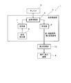
- FIG. 1 is a block diagram showing a configuration of a water vapor observation apparatus 1 according to an embodiment of the present invention. Below, the water vapor observation apparatus 1 which concerns on embodiment of this invention is demonstrated with reference to figures.
- the water vapor observation device 1 shown in FIG. 1 is configured to be able to calculate the distribution of the water vapor amount in the observation region by calculating the water vapor amount contained in each point in the observation region where the water vapor amount can be observed.
- the water vapor observation device 1 includes an antenna 2, a transmission / reception device 3, a calculation processing unit 10, and an operation / display device 4 (display).
- Antenna 2 is a radar antenna that can transmit pulsed radio waves (transmitted waves) with strong directivity.
- the antenna 2 is configured to receive a reflected wave from a target.
- the transmission wave transmitted from the antenna 2 travels in the distance direction (radial direction centered on the antenna 2), it passes through the water vapor existing in the middle and then reflects on the ground surface or the water surface (mainly the sea surface). Then, it is received by the antenna 2 as a received wave.
- the water vapor observation apparatus 1 measures the time from when the pulsed radio wave is transmitted until the reflected wave is received. Thereby, the water vapor observation device 1 can detect the distance from the water vapor observation device 1 (more precisely, the antenna 2) to the target.
- the antenna 2 is configured to be able to rotate 360 ° on a horizontal plane.
- the antenna 2 is configured to repeatedly transmit and receive radio waves at predetermined timings while changing the transmission direction of pulsed radio waves (changing the antenna angle).
- the water vapor observation device 1 can observe the amount of water vapor around the water vapor observation device 1 over 360 °.
- the reflected wave received by the antenna 2 is converted into a received signal and then output to the receiver 8.
- the operation from the transmission of a pulsed radio wave to the transmission of the next pulsed radio wave is referred to as “sweep”.
- the operation of rotating the antenna 360 ° while transmitting / receiving radio waves is called “scan”.
- the antenna 2 is configured to be able to transmit and receive two types of transmission waves and reception waves having different frequencies.
- the antenna 2 transmits a first transmission wave having a frequency of about 10 GHz and a second transmission wave having a frequency of about 22 GHz.
- the first transmission wave and the second transmission wave transmitted from the antenna 2 are reflected by the ground surface or the water surface after passing through the water vapor, respectively, and received by the antenna 2 as the first reception wave and the second reception wave.
- the first transmission wave and the second transmission wave may be transmitted alternately or may be transmitted simultaneously.
- the first received wave and the second received wave received by the antenna 2 are converted into a first received signal (first received information) and a second received signal (second received information), respectively.
- the reason for using the transmission wave having a frequency of about 10 GHz as described above and the second transmission wave having a frequency of about 22 GHz will be described.
- the attenuation constant (less than 0.01 dB / km) of an electromagnetic wave having a frequency of about 10 GHz the portion caused by water vapor is very small. That is, even if the 10 GHz transmission wave travels in the water vapor, it is not greatly attenuated by the water vapor.
- the portion caused by water vapor is relatively large in the attenuation constant (about 0.3 dB / km) of the electromagnetic wave having a frequency of about 22 GHz. That is, the second transmission wave is greatly attenuated due to the water vapor by traveling in the water vapor.
- the amount of water vapor at each point is estimated using this characteristic.
- the transmission / reception device 3 includes a transmission / reception switching unit 5, a signal generator 6, a transmitter 7, and a receiver 8.
- the transmission / reception switching unit 5 switches to a connection in which a transmission signal is transmitted from the transmitter 7 to the antenna 2 at the time of transmission.
- the transmission / reception switching unit 5 switches to a connection in which a reception signal (electric signal) from the antenna 2 is transmitted to the receiver 8 at the time of reception.
- the signal generator 6 generates a transmission signal that is the basis of the first transmission wave and the second transmission wave transmitted from the antenna 2. This transmission signal is amplified by the transmitter 7 and then output to the antenna 2 via the transmission / reception switching unit 5.
- the receiver 8 amplifies the reception signals (first reception signal and second reception signal) output from the antenna 2 and A / D converts the amplified reception signals. Thereafter, the receiver 8 outputs the received signal converted into the digital signal to the calculation processing unit 10.
- FIG. 2 is a block diagram showing a configuration of the calculation processing unit 10 shown in FIG.
- the calculation processing unit 10 is configured to calculate the amount of water vapor at each point in the observation area based on the first reception signal and the second reception signal output from the receiver 8.
- the calculation processing unit 10 includes a first echo level calculation unit 11, a second echo level calculation unit 12, a level difference detection unit 13, a water vapor amount conversion unit 14, and a water vapor amount per distance position.
- the calculation processing unit 10 includes, for example, a processor (CPU, FPGA, etc.) not shown and a device such as a memory.
- the CPU reads the program from the memory and executes it, so that the calculation processing unit 10 is changed to a first echo level calculation unit 11, a second echo level calculation unit 12, a level difference detection unit 13, a water vapor amount conversion unit 14, and It can function as the water vapor amount calculation unit 15 for each distance position.
- the first echo level calculation unit 11 receives a reception signal (first reception wave) obtained from a reflected wave (first reception wave) of the first transmission wave arriving from each azimuth direction with reference to the reference position that is the installation position of the antenna 2. Signal), the echo level (signal intensity) from each distance position in each azimuth direction is calculated.
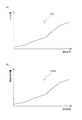
- FIG. 3A is a graph in which each sample constituting an echo signal from a certain azimuth direction is plotted on the coordinates where the horizontal axis is the distance position and the vertical axis is the echo level of the echo signal derived from each distance position.
- First echograph EG 1 The first echo level calculation unit 11 generates a first echo graph EG 1 as shown in FIG.
- the above-described distance position refers to a position away from the antenna 2 by that distance when the antenna 2 is used as a reference.
- a position where the distance position in a certain azimuth direction is 1 km is a position along the certain azimuth direction and 1 km away from the antenna 2.
- the second echo level calculation unit 12 determines each direction based on a reception signal (second reception signal) obtained from a reflected wave (second reception wave) of the second transmission wave that arrives from each direction with respect to the antenna 2. The echo level from each distance position in the direction is calculated.
- FIG. 3B is a graph in which each sample constituting an echo signal from a certain azimuth direction is plotted on the coordinates where the horizontal axis is the distance position and the vertical axis is the level of the echo signal derived from each distance position ( A second echograph EG 2 ).
- the second echo level calculation unit 12 generates a second echo graph EG 2 as shown in FIG.
- the level difference detection unit 13 includes the echo level of the first received wave returned from a certain point (reflection point) calculated by the first echo level calculation unit 11 and the certain point calculated by the second echo level calculation unit 12.
- the level difference ⁇ Lv between the echo level of the second received wave coming back from is calculated.
- the level difference detection unit 13 calculates the level difference ⁇ Lv at each point in the observation area.
- FIG. 4A is a graph in which the level difference ⁇ Lv calculated for each distance position in a certain azimuth direction is plotted on the coordinates where the horizontal axis is the distance position and the vertical axis is the level difference ⁇ Lv at each distance position. (Level difference graph DG). That is, the graph shown in FIG.
- the level difference detection unit 13 generates a level difference graph DG as shown in FIG. 4 for each direction.
- FIG. 4B is a graph generated by the water vapor amount conversion unit 14 and is a graph in which the vertical axis of FIG. 4A is converted into the water vapor amount.
- the water vapor amount conversion unit 14 converts the level difference ⁇ Lv for each point detected by the level difference detection unit 13 into a water vapor amount.
- the water vapor amount conversion unit 14 has a correspondence relationship between the level difference ⁇ Lv for each distance position and the water vapor amount included in the range from the reference position (the position of the antenna 2) to each distance position. Is used to convert the level difference ⁇ Lv for each distance position into the amount of water vapor included in the range up to each distance position.
- the graph generated by the water vapor amount conversion unit 14 see FIG.
- this graph is generated as a cumulative water vapor amount graph AWG in which the water vapor amount gradually increases along the horizontal axis direction.
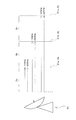
- FIG. 5 schematically shows the first and second transmitted waves transmitted from the antenna 2 and the first and second received waves reflected and returned from a specific reflection target (the ground surface portion or the water surface).
- FIG. FIG. 5 shows an example in which the echo intensity of the first and second transmission waves is 10, the echo intensity of the first reception wave is 7, and the echo intensity of the second reception wave is 6.
- the ground surface portion or water surface
- the ground surface portion is schematically shown in a triangular shape, but actually, the ground surface portion (or water surface) spreads along the traveling direction of the transmitted and received waves.
- an electromagnetic wave having a frequency of about 10 GHz is not greatly attenuated due to water vapor. Therefore, it is considered that the difference between the echo intensity 10 of the first transmission wave and the echo intensity 7 of the first reception wave (that is, the attenuation amount of the first transmission wave) is caused by factors other than water vapor.
- electromagnetic waves having a frequency of about 22 GHz are greatly attenuated due to water vapor. Therefore, it is considered that the difference between the echo intensity 10 of the second transmission wave and the echo intensity 6 of the second reception wave (that is, the attenuation amount of the second transmission wave) is caused by factors other than water vapor and water vapor.
- the level difference ⁇ Lv between the echo intensity 7 of the first received wave and the echo intensity 6 of the second received wave is caused by the amount of water vapor contained in the region Z through which the transmitted wave has passed. Therefore, it can be considered that there is a correspondence between the level difference ⁇ Lv and the amount of water vapor included in the range from the antenna 2 to each distance position.
- FIG. 6 is a water vapor amount graph WG for each distance position generated by the water vapor amount calculation unit 15 for each distance position, and the graph (cumulative water vapor amount graph AWG) shown in FIG. 4B is differentiated for each distance position. It is the graph obtained.
- the water vapor amount calculation unit 15 for each distance position generates a water vapor amount graph WG for each distance position obtained by differentiating the cumulative water vapor amount graph AWG generated by the water vapor amount conversion unit 14 in the distance direction.
- the water vapor amount calculation unit 15 for each distance position generates the water vapor amount graph WG for each distance position for each azimuth with the antenna 2 as a reference, integrates them, and at each distance position in each azimuth centered on the antenna 2.
- a water vapor distribution diagram DM showing the amount of water vapor is generated.
- FIG. 7 is a diagram showing an example of the water vapor distribution diagram DM displayed on the operation / display device 4 and is a diagram showing an enlarged part thereof.
- the operation / display device 4 displays the water vapor distribution diagram DM generated by the water vapor amount calculation unit 15 for each distance position.
- the operation / display device 4 displays a color tone corresponding to the amount of water vapor at each point on the map including the point where the water vapor observation device 1 is installed. Thereby, the user can grasp
- the above-described colors are shown corresponding to the dot density. Specifically, high-density dots are displayed at points where the amount of water vapor is high, and low-density dots are displayed at points where the amount of water vapor is low.
- the first reception signal and the second reception obtained from the reflected waves of electromagnetic waves in two frequency bands (near 10 GHz and 22 GHz) having different degrees of attenuation due to water vapor. Based on the signal, the amount of water vapor contained in the region through which the electromagnetic wave has passed is calculated. If it carries out like this, it will become possible to remove the attenuation amount of the transmission wave by factors other than water vapor, and it will be possible to extract only the attenuation amount of the transmission wave due to water vapor. Thereby, the amount of water vapor contained in the region through which the electromagnetic wave has passed can be calculated.
- the reflected wave that is reflected by the ground surface or the water surface after passing through the water vapor is received as a received wave.
- the surface portion of the earth is constituted by the surface portion and the water surface (mainly the sea surface). Therefore, by calculating the water vapor amount based on the ground surface portion and the reflected wave on the water surface, it is possible to calculate the water vapor amount in all regions on the ground by appropriately selecting the installation position of the antenna 2. .
- the water vapor observation apparatus 1 it is possible to reliably calculate the water vapor amount at a desired position.
- the amount of water vapor contained in the region through which the electromagnetic wave has passed is calculated based on the level difference between the first reception signal and the second reception signal. In this way, the attenuation amount of the transmission wave due to factors other than water vapor is appropriately removed, and only the attenuation amount of the transmission wave due to water vapor is extracted. Thereby, the amount of water vapor contained in the region through which the electromagnetic wave has passed can be calculated.
- the amount of water vapor contained from the installation position of the antenna 2 to the reflection point of the received signal can be appropriately calculated. Can do.
- the water vapor observation apparatus 1 is provided with the antenna 2 as a transmission / reception unit capable of transmitting / receiving electromagnetic waves, the part for transmitting and receiving the electromagnetic waves can be integrated. As a result, the entire water vapor observation apparatus 1 can be made compact.
- the water vapor observation apparatus 1 detects a level difference ⁇ Lv at each point in the same direction with respect to the position of the antenna 2 and converts the level difference ⁇ Lv into a water vapor amount.
- a level difference ⁇ Lv since there is a correspondence between the level difference ⁇ Lv and the amount of water vapor included in the range from the antenna 2 to each distance position, each distance from the antenna 2 can be detected by detecting the level difference ⁇ Lv.
- the amount of water vapor included in the range up to the position can be calculated appropriately.
- the amount of water vapor at each point is calculated by differentiating the cumulative water vapor amount graph AWG. Thereby, the amount of water vapor at each point can be calculated appropriately and easily.
- the water vapor amount at each point is indicated by a color tone as an index representing the water vapor amount.
- a water vapor distribution diagram DM indicating the amount of water vapor at each distance position in each direction centered on the antenna 2 is displayed on the operation / display device 4.
- the user can grasp
- FIG. 8 is a block diagram showing a configuration of a water vapor observation apparatus 1a according to a modification.
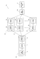
- FIG. 9 is a plan view schematically showing the positional relationship between the transmission unit 20 (transmission antenna 2a) and the reception unit 21 (reception antenna 2b) shown in FIG.
- the position of the transmission unit 20 is schematically illustrated by a circle with no hatching
- the position of the reception unit 21 is schematically illustrated by a circle with hatching.
- the water vapor observation apparatus 1a according to the present modification includes a transmission unit 20 that is a unit that transmits a transmission wave, a plurality of reception units 21 that are units that receive a reception wave, a calculation processing unit 10a, And an operation / display device 4.
- the transmission unit 20 includes a transmission antenna 2a, a signal generator 6, and a transmitter 7.
- the transmission antenna 2a is for transmitting a transmission wave, and is configured to transmit each of the first transmission wave and the second transmission wave, similarly to the antenna 2 of the above-described embodiment.
- the transmission signals that are the basis of the first transmission wave and the second transmission wave generated by the signal generator 6 are amplified by the transmitter 7 and then output to the antenna 2 a.
- Each receiving unit 21 is arranged at a different position from the transmitting unit 20. As shown in FIG. 9, the wave receiving units 21 are arranged in a lattice shape with the wave transmitting unit 20 as the center. Each receiving unit 21 includes a receiving antenna 2b and a receiver 8a.
- the receiving antenna 2b is for receiving a received wave, and is configured to receive each of the first received wave and the second received wave, similarly to the antenna 2 of the above-described embodiment.
- the received wave received by the receiving antenna 2b is converted into the first received signal and the second received signal as in the case of the above embodiment, and then amplified and A / D converted by the corresponding receiver 8a. And transmitted to the calculation processing unit 10a by wireless or the like.
- FIG. 10 is a block diagram showing a configuration of the calculation processing unit shown in FIG.
- FIG. 11 is a diagram schematically illustrating how the first and second transmission waves transmitted by the transmission antenna 2a are received as reception waves by the reception antennas 2b.
- direction is typically shown with the broken line.
- the reference numerals of the receiving units are 21a, 21b, and 21c in order from the side closer to the transmitting antenna 2a.
- the calculation processing unit 10a includes a first echo level calculation unit 11a, a second echo level calculation unit 12a, a level difference detection unit 13a, a water vapor amount conversion unit 14a, and a water vapor amount per distance position. And a calculation unit 15a.
- the first echo level calculation unit 11a calculates the echo level of the first reception signal obtained from the first reception wave that has reached the reception antenna 2b among the first transmission waves transmitted from the transmission antenna 2a. To do. The first echo level calculation unit 11a calculates the echo level of the first reception signal obtained by each receiving antenna 2b.
- the second echo level calculation unit 12a calculates the echo level of the second reception signal obtained from the second reception wave that has reached the reception antenna 2b among the second transmission waves transmitted from the transmission antenna 2a. To do. The second echo level calculation unit 12a calculates the echo level of the second received signal obtained by each receiving antenna 2b.
- the level difference detection unit 13a detects a level difference between the echo level of the first reception signal obtained by each reception antenna 2b and the echo level of the second reception signal obtained by the same reception antenna 2b. To do.
- the water vapor amount conversion unit 14a converts the level difference for each wave receiving unit 21 detected by the level difference detection unit 13 into a water vapor amount. Specifically, the water vapor amount conversion unit 14 has a correspondence relationship between the level difference detected for each wave receiving unit 21 and the water vapor amount included in the range from the wave transmitting unit 20 to each wave receiving unit 21. Utilizing the fact, the level difference detected for each wave receiving unit 21 is converted into the amount of water vapor included in the range from the wave transmitting unit 20 to each wave receiving unit 21.
- the water vapor amount calculation unit 15a for each distance position includes the adjacent receiving units 21 among the receiving units 21 arranged linearly in the same direction (in the example shown in FIG. 11, the receiving units 21a and 21b, the receiving units 21b and 21c). ), The water vapor amount at each point in the observation region (each small region included in the observation region) is calculated. Specifically, the water vapor amount calculation unit 15a for each distance position refers to FIG. 11, and the water vapor amount calculated by the wave receiving unit 21b (that is, the water vapor amount contained in the areas Za and Zb) and the wave receiving unit. The amount of water vapor contained in region Zb is calculated by taking the difference from the amount of water vapor calculated in 21a (ie, the amount of water vapor contained in region Za).
- the water vapor amount calculation unit 15a for each distance position calculates the water vapor amount calculated by the wave receiving unit 21c (that is, the water vapor amount contained in the areas Za, Zb, and Zc) and the water vapor amount calculated by the wave receiving unit 21b.
- the amount of water vapor contained in the region Zc is calculated by taking the difference from (that is, the amount of water vapor contained in the regions Za and Zb).
- the water vapor amount calculation unit 15a for each distance position performs the same process for other wave receiving units adjacent in the azimuth direction. Thereby, also in the water vapor observation apparatus 1a according to the present modification, the water vapor amount at each point in the observation region is calculated as in the case of the water vapor observation apparatus 1 according to the above-described embodiment.
- the transmitting antenna 2a and the receiving antenna 2b are arranged at different positions. Based on the difference between the first and second received waves having different frequencies received by the receiving antenna 2b, the amount of water vapor contained in the region through which the received wave has passed is calculated.
- the arrangement of the receiving antenna 2b is set so that the region where the water vapor amount is to be calculated is sandwiched between the receiving antenna 2a and the water vapor amount at a desired position is reliably calculated. can do.
- the two receiving antennas 2b (see, for example, FIG. 11) have the same orientation with respect to the transmitting antenna 2a and have different distances from the transmitting antenna 2a. Then, the receiving antennas of the receiving units 21a and 21b and the receiving antennas of the receiving units 21b and 21c) are arranged. In the case of the water vapor observation device 1a, by arranging these two receiving antennas 2b so as to sandwich the region where the water vapor amount is to be calculated, the water vapor amount at a desired position can be ensured regardless of the position of the transmitting antenna 2a. Can be calculated.
- the receiving antennas 2b are arranged in a lattice pattern, so that the amount of water vapor in each small region within the region where the receiving antennas 2b are arranged in a lattice pattern can be calculated. it can.
- FIG. 12 is a plan view schematically showing the positional relationship between the wave transmitting unit 20 and the wave receiving unit 21 included in the water vapor observation apparatus according to the modification, and is a view corresponding to FIG.
- the wave receiving units 21 are arranged in a lattice pattern, but the present invention is not limited to this.
- two receiving units 21 may be arranged at positions where the directions with respect to the transmitting unit 20 are the same and the distances from the transmitting unit 20 are different. .
- this modification for example, by installing two receiving units 21 so as to sandwich a region where the amount of water vapor is to be observed, the number of necessary receiving units 21 is reduced and the amount of water vapor in a desired region is observed. can do.
- transmission of a transmission wave and reception of a reception wave are performed by one antenna 2.
- the present invention is not limited thereto, and a transmission antenna and a reception antenna are provided. May be arranged at different positions.
- an electromagnetic wave having a frequency of about 10 GHz and an electromagnetic wave having a frequency of about 22 GHz are used as the transmission wave, but this is not a limitation. Specifically, an electromagnetic wave of any frequency band may be used as a transmission wave as long as the transmission constant is a portion of the attenuation constant caused by water vapor.
- FIG. 13 is a block diagram illustrating a configuration of the calculation processing unit 10b of the water vapor observation apparatus according to the modification.
- the water vapor amount calculation unit 15 for each distance position is provided and the water vapor amount at each point in the observation region is calculated, but the present invention is not limited to this.
- a configuration in which the water vapor amount calculation unit 15 for each distance position is omitted may be used as in this modification. In this case, the amount of water vapor contained in the region from the position of the antenna 2 to each point in each azimuth can be calculated.
- the cumulative water vapor amount graph AWG (see FIG. 4B) is differentiated in the distance direction, and the water vapor amount at each distance position is calculated for each azimuth.
- the present invention is not limited to this, and after detecting the level difference ⁇ Lv at each of the two points, the water vapor amount may be calculated by taking the difference between these level differences ⁇ Lv.
- a plurality of receiving antennas are installed for the amount of water contained in the desired region as shown in FIG. Can be calculated without any problem.
- the water vapor distribution diagram DM is displayed on the operation / display device 4
- the present invention is not limited thereto.
- the water vapor amount at a predetermined point may be displayed as a numerical value on the operation / display device 4.
- FIG. 14 is a diagram schematically showing the positional relationship between the wave transmitting unit 22 and the wave receiving unit 23 of the water vapor observation apparatus according to the modification, and is a diagram corresponding to FIG.
- the wave receiving units 21 are arranged in a lattice shape.
- the arrangement is not limited to this, and other arrangements may be used.
- the receiving units 23 may be arranged radially with the transmitting unit 22 as the center.
- the wave receiving units may be arranged in a three-dimensional shape instead of a two-dimensional shape.
- FIG. 15 is a block diagram showing a configuration of a water vapor observation apparatus 1b according to a modification.
- the water vapor observation device 1b according to the present modification does not include the operation / display device 4, and instead, data related to the water vapor distribution map DM is transmitted to the external device 50.
- An interface 16 for output is provided. Examples of the interface 16 include a connector to which a cable is connected as an example. Examples of the external device 50 include a display on which the water vapor distribution diagram DM is displayed. According to the water vapor observation device 1b, information related to the amount of water vapor calculated by the calculation processing unit 10 can be displayed on an external device.
Landscapes
- Physics & Mathematics (AREA)
- Remote Sensing (AREA)
- Radar, Positioning & Navigation (AREA)
- Engineering & Computer Science (AREA)
- General Physics & Mathematics (AREA)
- Electromagnetism (AREA)
- Analytical Chemistry (AREA)
- Biochemistry (AREA)
- General Health & Medical Sciences (AREA)
- Chemical & Material Sciences (AREA)
- Immunology (AREA)
- Pathology (AREA)
- Life Sciences & Earth Sciences (AREA)
- Health & Medical Sciences (AREA)
- Computer Networks & Wireless Communication (AREA)
- Radar Systems Or Details Thereof (AREA)
Abstract
Priority Applications (3)
| Application Number | Priority Date | Filing Date | Title |
|---|---|---|---|
| US15/748,063 US10502696B2 (en) | 2015-07-28 | 2016-06-08 | Water vapor observing apparatus |
| EP16830167.9A EP3330700B1 (fr) | 2015-07-28 | 2016-06-08 | Dispositif d'observation de vapeur d'eau |
| JP2017531064A JP6586462B2 (ja) | 2015-07-28 | 2016-06-08 | 水蒸気観測装置 |
Applications Claiming Priority (2)
| Application Number | Priority Date | Filing Date | Title |
|---|---|---|---|
| JP2015148468 | 2015-07-28 | ||
| JP2015-148468 | 2015-07-28 |
Publications (1)
| Publication Number | Publication Date |
|---|---|
| WO2017018062A1 true WO2017018062A1 (fr) | 2017-02-02 |
Family
ID=57885685
Family Applications (1)
| Application Number | Title | Priority Date | Filing Date |
|---|---|---|---|
| PCT/JP2016/066985 Ceased WO2017018062A1 (fr) | 2015-07-28 | 2016-06-08 | Dispositif d'observation de vapeur d'eau |
Country Status (4)
| Country | Link |
|---|---|
| US (1) | US10502696B2 (fr) |
| EP (1) | EP3330700B1 (fr) |
| JP (1) | JP6586462B2 (fr) |
| WO (1) | WO2017018062A1 (fr) |
Cited By (3)
| Publication number | Priority date | Publication date | Assignee | Title |
|---|---|---|---|---|
| WO2021161705A1 (fr) * | 2020-02-14 | 2021-08-19 | 古野電気株式会社 | Dispositif d'observation de vapeur d'eau, système d'observation de vapeur d'eau, procédé d'observation de vapeur d'eau et programme d'observation de vapeur d'eau |
| US20220235175A1 (en) * | 2019-12-02 | 2022-07-28 | Octal, Inc. | Multimodal polyalkylene terephthalate |
| JP2023044369A (ja) * | 2021-09-17 | 2023-03-30 | 日本アンテナ株式会社 | 水蒸気量観測システム |
Families Citing this family (1)
| Publication number | Priority date | Publication date | Assignee | Title |
|---|---|---|---|---|
| EP3926332A4 (fr) | 2019-02-12 | 2022-10-12 | Furuno Electric Co., Ltd. | Instrument d'observation de vapeur d'eau et procédé d'observation de vapeur d'eau |
Citations (4)
| Publication number | Priority date | Publication date | Assignee | Title |
|---|---|---|---|---|
| JPS5062083A (fr) * | 1973-10-01 | 1975-05-27 | ||
| JPH02280083A (ja) * | 1989-04-20 | 1990-11-16 | Nec Corp | 水蒸気量・雨量測定装置 |
| CN102636500A (zh) * | 2012-04-16 | 2012-08-15 | 湖南中大智能科技有限公司 | 基于射频的湿度测量方法 |
| JP2013224884A (ja) * | 2012-04-23 | 2013-10-31 | Japan Radio Co Ltd | 水蒸気観測装置および気象レーダ |
Family Cites Families (7)
| Publication number | Priority date | Publication date | Assignee | Title |
|---|---|---|---|---|
| GB1078111A (en) | 1963-02-13 | 1967-08-02 | Microwave Instr Ltd | Improvements in or relating to the detection and measurement of water vapour in gases |
| JP5247874B2 (ja) * | 2011-12-06 | 2013-07-24 | パナソニック株式会社 | 蓄電池移転支援装置および蓄電池移転支援方法 |
| EP4109095A1 (fr) * | 2014-09-09 | 2022-12-28 | Perosphere Technologies Inc. | Test de coagulation universel fondé sur une puce microfluidique |
| CN107106039B (zh) * | 2014-11-14 | 2020-08-11 | 皇家飞利浦有限公司 | 切片中的沿着一维延伸的磁共振指纹识别 |
| DE102014226262B4 (de) * | 2014-12-17 | 2016-08-04 | Siemens Healthcare Gmbh | Untersuchungsobjekt-spezifisches Erfassen von Magnetresonanz-Bilddaten mittels einer Magnetresonanz-Sequenz, welche zumindest einen adiabatischen Hochfrequenz-Puls umfasst |
| CN107171030B (zh) * | 2016-03-08 | 2022-02-11 | 松下知识产权经营株式会社 | 蓄电系统及蓄电系统的控制方法 |
| US10495709B2 (en) * | 2016-07-25 | 2019-12-03 | Siemens Healthcare Gmbh | Multi-contrast simultaneous multislice magnetic resonance imaging with binomial radio-frequency pulses |
-
2016
- 2016-06-08 WO PCT/JP2016/066985 patent/WO2017018062A1/fr not_active Ceased
- 2016-06-08 US US15/748,063 patent/US10502696B2/en active Active
- 2016-06-08 EP EP16830167.9A patent/EP3330700B1/fr active Active
- 2016-06-08 JP JP2017531064A patent/JP6586462B2/ja active Active
Patent Citations (4)
| Publication number | Priority date | Publication date | Assignee | Title |
|---|---|---|---|---|
| JPS5062083A (fr) * | 1973-10-01 | 1975-05-27 | ||
| JPH02280083A (ja) * | 1989-04-20 | 1990-11-16 | Nec Corp | 水蒸気量・雨量測定装置 |
| CN102636500A (zh) * | 2012-04-16 | 2012-08-15 | 湖南中大智能科技有限公司 | 基于射频的湿度测量方法 |
| JP2013224884A (ja) * | 2012-04-23 | 2013-10-31 | Japan Radio Co Ltd | 水蒸気観測装置および気象レーダ |
Non-Patent Citations (1)
| Title |
|---|
| See also references of EP3330700A4 * |
Cited By (6)
| Publication number | Priority date | Publication date | Assignee | Title |
|---|---|---|---|---|
| US20220235175A1 (en) * | 2019-12-02 | 2022-07-28 | Octal, Inc. | Multimodal polyalkylene terephthalate |
| US11667753B2 (en) * | 2019-12-02 | 2023-06-06 | Octal, Inc. | Multimodal polyalkylene terephthalate |
| WO2021161705A1 (fr) * | 2020-02-14 | 2021-08-19 | 古野電気株式会社 | Dispositif d'observation de vapeur d'eau, système d'observation de vapeur d'eau, procédé d'observation de vapeur d'eau et programme d'observation de vapeur d'eau |
| US11703462B2 (en) | 2020-02-14 | 2023-07-18 | Furuno Electric Co., Ltd. | Water vapor observation device, water vapor observation system, water vapor observation method, and recording medium |
| JP2023044369A (ja) * | 2021-09-17 | 2023-03-30 | 日本アンテナ株式会社 | 水蒸気量観測システム |
| JP7739103B2 (ja) | 2021-09-17 | 2025-09-16 | 日本アンテナ株式会社 | 水蒸気量観測システム |
Also Published As
| Publication number | Publication date |
|---|---|
| EP3330700A4 (fr) | 2019-03-20 |
| JPWO2017018062A1 (ja) | 2018-05-24 |
| US10502696B2 (en) | 2019-12-10 |
| US20180209920A1 (en) | 2018-07-26 |
| EP3330700B1 (fr) | 2021-02-24 |
| EP3330700A1 (fr) | 2018-06-06 |
| JP6586462B2 (ja) | 2019-10-02 |
Similar Documents
| Publication | Publication Date | Title |
|---|---|---|
| JP5395692B2 (ja) | 気象レーダ装置及び気象観測方法 | |
| KR101890974B1 (ko) | 좁은 안테나 로브와 넓은 탐지각도 범위를 가진 이미징 레이더 센서 | |
| CN110645886A (zh) | 一种地基干涉虚拟孔径形变监测雷达系统及工作方法 | |
| JP6586462B2 (ja) | 水蒸気観測装置 | |
| JPWO2015005020A1 (ja) | 気象情報処理装置、気象レーダシステムおよび気象情報処理方法 | |
| EP3330746B1 (fr) | Système d'observation de vapeur d'eau | |
| JP5238531B2 (ja) | レーダ装置、海洋レーダ観測装置およびドップラ周波数データ算出方法 | |
| JP5996259B2 (ja) | 津波検出装置、津波検出方法及び津波検出プログラム | |
| JP6712313B2 (ja) | 信号処理装置及びレーダ装置 | |
| US10809369B2 (en) | Radar signal processing apparatus and radar signal processing method | |
| JP2007248293A (ja) | 海洋レーダ装置 | |
| GB2460744A (en) | Underwater detection device | |
| JP6264194B2 (ja) | レーダ装置 | |
| JP5491788B2 (ja) | 気象レーダシステムとその降水強度算出方法 | |
| CN103852595B (zh) | 一种低空风探测的方法 | |
| JP5196959B2 (ja) | レーダ装置 | |
| CN116184534A (zh) | 一种降雨量的测量方法及相关装置 | |
| JP2010085329A (ja) | 物体検出システム、該物体検出システムに用いられる物体検出方法及び物体検出制御プログラム | |
| JP6703829B2 (ja) | 信号処理装置、レーダ装置、水中探知装置、信号処理方法、および、プログラム | |
| JP6138430B2 (ja) | 危険物標検出装置 | |
| EP4067936B1 (fr) | Dispositif radar à semi-conducteurs | |
| KR102089509B1 (ko) | 불청 범위 제거용 레이더 | |
| JP2014021031A (ja) | 目標観測支援装置 |
Legal Events
| Date | Code | Title | Description |
|---|---|---|---|
| 121 | Ep: the epo has been informed by wipo that ep was designated in this application |
Ref document number: 16830167 Country of ref document: EP Kind code of ref document: A1 |
|
| ENP | Entry into the national phase |
Ref document number: 2017531064 Country of ref document: JP Kind code of ref document: A |
|
| WWE | Wipo information: entry into national phase |
Ref document number: 15748063 Country of ref document: US |
|
| NENP | Non-entry into the national phase |
Ref country code: DE |
|
| WWE | Wipo information: entry into national phase |
Ref document number: 2016830167 Country of ref document: EP |