WO2017018178A1 - Faisceau de fils et procédé de fabrication de celui-ci - Google Patents
Faisceau de fils et procédé de fabrication de celui-ci Download PDFInfo
- Publication number
- WO2017018178A1 WO2017018178A1 PCT/JP2016/070344 JP2016070344W WO2017018178A1 WO 2017018178 A1 WO2017018178 A1 WO 2017018178A1 JP 2016070344 W JP2016070344 W JP 2016070344W WO 2017018178 A1 WO2017018178 A1 WO 2017018178A1
- Authority
- WO
- WIPO (PCT)
- Prior art keywords
- harness
- connector
- branch
- branch line
- line
- Prior art date
- Legal status (The legal status is an assumption and is not a legal conclusion. Google has not performed a legal analysis and makes no representation as to the accuracy of the status listed.)
- Ceased
Links
Images


Classifications
-
- B—PERFORMING OPERATIONS; TRANSPORTING
- B60—VEHICLES IN GENERAL
- B60R—VEHICLES, VEHICLE FITTINGS, OR VEHICLE PARTS, NOT OTHERWISE PROVIDED FOR
- B60R16/00—Electric or fluid circuits specially adapted for vehicles and not otherwise provided for; Arrangement of elements of electric or fluid circuits specially adapted for vehicles and not otherwise provided for
- B60R16/02—Electric or fluid circuits specially adapted for vehicles and not otherwise provided for; Arrangement of elements of electric or fluid circuits specially adapted for vehicles and not otherwise provided for electric constitutive elements
- B60R16/0207—Wire harnesses
- B60R16/0215—Protecting, fastening and routing means therefor
-
- H—ELECTRICITY
- H01—ELECTRIC ELEMENTS
- H01B—CABLES; CONDUCTORS; INSULATORS; SELECTION OF MATERIALS FOR THEIR CONDUCTIVE, INSULATING OR DIELECTRIC PROPERTIES
- H01B13/00—Apparatus or processes specially adapted for manufacturing conductors or cables
- H01B13/012—Apparatus or processes specially adapted for manufacturing conductors or cables for manufacturing wire harnesses
- H01B13/01263—Tying, wrapping, binding, lacing, strapping or sheathing harnesses
-
- H—ELECTRICITY
- H02—GENERATION; CONVERSION OR DISTRIBUTION OF ELECTRIC POWER
- H02G—INSTALLATION OF ELECTRIC CABLES OR LINES, OR OF COMBINED OPTICAL AND ELECTRIC CABLES OR LINES
- H02G3/00—Installations of electric cables or lines or protective tubing therefor in or on buildings, equivalent structures or vehicles
- H02G3/02—Details
- H02G3/04—Protective tubing or conduits, e.g. cable ladders or cable troughs
- H02G3/0462—Tubings, i.e. having a closed section
Definitions
- the present invention relates to a wire harness having a plurality of parts divided from each other, and the divided parts being coupled to each other via a connector, and a method for manufacturing the same.
- Patent Literature 1 discloses a technique of dividing a wire harness mounted on an automobile into a plurality of sub-harnesses and connecting the divided sub-harnesses via connectors.
- the inventors of the present invention paid attention to a branching portion which is a connecting portion between the main line portion and the branch line portion as a division portion suitable for rationalization of the assembly of the wire harness.
- Dividing the main line part and the branch line part in this branching part means, for example, that the branch line part connected to the device of the terminal is changed to the type or grade of the apparatus while using the common main line part.
- the branch portion As a division location, that is, to divide the main line portion and the branch line portion and to connect the connectors provided on both at the branch portion.
- the large load acting on the branch part is the main line side connector and the branch line side connector.
- the present invention has an object to provide a wire harness in which a main line portion and a branch line portion are divided from each other, and the divided portion can be effectively protected from a large load.
- the wire harness provided by the present invention includes a trunk wire harness including a plurality of electric wires bundled together and a plurality of electric wires bundled together, and a branch line connectable to the trunk wire harness so as to branch from a middle portion of the trunk wire harness.
- a harness, a trunk connector provided in the middle of the trunk harness, and an electrical wire included in the trunk harness by being coupled to the trunk connector provided at an end of the branch harness and the branch harness A branch line connector that electrically connects the electric wires to each other; and a connector protector for protecting the main line connector and the branch line connector from a load acting on the branch line harness.
- the said connector protector contains the connector protection member arrange
- the connector protection member includes a main line side connection portion connected and fixed to the main line harness, and a branch line side connection portion connected and fixed to the branch line connector, the main line side connection portion and the branch line side connection portion.
- the main line side connecting part and the branch line side connecting part are integrally connected so as to fix the relative position between the main line connector and the branch line connector against a load acting on the branch line harness. regulate.
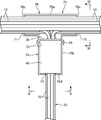
- FIG. 3 is a view showing a cross section taken along line III-III in FIG. 2.
- FIG. 4 is a view showing a cross section taken along line IV-IV in FIG. 2.
- FIG. 4 is a perspective view of the connector protection member which comprises the wire harness shown by FIG. It is a bottom view of the connector protection member. It is a side view of the said connector protection member. It is a perspective view which shows the principal part of the wire harness which concerns on the 2nd Embodiment of this invention.
- FIG. 10 is a view showing a cross section taken along line XX of FIG. 9.
- FIG. 10 is a view showing a cross section taken along line XI-XI in FIG. 9; It is a perspective view of the harness protector.
- the wire harness includes a main line harness 10, a branch line harness 20, a main line connector 30, a branch line connector 40, and a connector protector 50.
- the trunk harness 10 includes a plurality of electric wires 12 that are bundled together.
- the branch harness 20 includes a plurality of electric wires 22 bundled with each other, and can be connected to the main line harness 10 so as to branch from an intermediate portion of the main line harness 10.
- the main line connector 30 is provided in the middle part of the main line harness. Specifically, the main line connector 30 is provided at the end of the electric wire 12 to be branched and connected to the branch line harness 20 among the electric wires 12 included in the main line harness 10.
- the main line connector 30 has a plurality of connector terminals that are respectively attached to the ends of the electric wires 12 to be branched and a connector housing that holds these connector terminals. Of these, only the connector housing is illustrated in FIG. 1 to 4 are shown.
- the branch line connector 40 is provided at one end of the branch line harness 20 at a base end part to be connected to the main line harness 10, and is included in the main line harness 10 by being coupled to the main line connector 30.
- the branch connection target electric wires 12 and the electric wires 22 included in the branch harness 20 are electrically connected to each other.
- the branch line connector 40 has a plurality of connector terminals respectively attached to the ends of the plurality of electric wires 22, and a connector housing for holding these connector terminals, and only the connector housing is shown in FIGS. 4.
- various devices to be connected to the end of the wire harness are connected to the distal end which is the other end of the branch harness 20.
- the connector protector 50 is for protecting the trunk line connector 30 and the branch line connector 40 from a load acting on the branch line harness 20, particularly a tensile load indicated by an arrow At in FIG.
- the connector protection member 60 is made of a single plate material, and integrally includes a main line side connecting portion 62 and a branch line side connecting portion 64.
- the main line side connecting portion 62 is a portion that is connected to and fixed to the main line harness 10 and has a shape that extends along the longitudinal direction of the main line harness 10.
- the main line side connecting portion 62 according to this embodiment has a substantially rectangular shape having a certain width in a direction orthogonal to the longitudinal direction of the main line harness 10.
- the branch line side connecting portion 64 is a portion that is connected and fixed to the branch line connector 40, and in this embodiment, the branch line side connecting portion 64 is branched in the longitudinal direction so as to branch from the middle portion in the longitudinal direction of the main line side connecting portion 62. It extends in the direction orthogonal to the direction.
- the branch line side connecting portion 64 also has a substantially rectangular shape having a certain width in a direction orthogonal to the longitudinal direction of the branch line side connecting portion 64, similarly to the main line side connecting portion 62.
- the branch line side connecting part 64 and the branch line connector 40 further have engaging parts 66 and 46 as shown in FIG. These engaging portions 66 and 46 are engaged with each other, so that the branch connector 40 is relatively displaced in the direction in which the branch connector 40 is separated from the main line side connecting portion 62 (downward in FIGS. 2 and 3).
- the engaging portion 66 of the branch line side connecting portion 64 has a shape that protrudes toward the branch line connector 40 on the surface (back surface) of the branch line side connecting portion 64 that faces the branch line connector 40.
- the engaging portion 46 of the branch line connector 40 has a recessed shape so as to accept the fitting of the engaging portion 66 on the outer surface of the connector housing of the branch line connector 40 that faces the branch line side connecting portion 64.
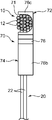
- the connector protector 50 further includes a main line binding tool 52 and a branch line binding tool 54.
- the trunk wire tying member 52 is made of, for example, an adhesive tape, and sandwiches a predetermined portion of the trunk line side coupling portion 62, in this embodiment, a central portion of the trunk line side coupling portion 62 connected to the branch line side coupling portion 64. It winds around the said trunk line harness 10 so that it may be stuck ranging over the site
- the main line tying member 52 binds the main line harness 10 and the main line side connecting portion 62, thereby fixing the main line side connecting portion 62 to the main line harness 10.
- the branch line tying member 54 is also made of, for example, an adhesive tape having a certain width, and is connected to the branch line side connecting portion 64 and the branch line connector 44 in a state where the engaging portions 66 and 46 are engaged with each other. It is wound so as to be attached to the branch line side connecting portion 64 and the branch line connector 44 across the bridge.
- the branch line binding tool 54 binds the branch line side connecting portion 64 and the branch line connector 40, thereby fixing the branch line side connecting portion 64 to the branch line connector 40.
- Each of the binding tools 52 and 54 can be constituted by a binding tool other than the adhesive tape, for example, a binding band that does not have an adhesive force but has a strong clamping force.
- positioning protrusions 63 are formed that protrude to both outer sides in the width direction from other portions. These positioning projections 63 are for regulating the position of the outer end of the trunk line tying member 54 wound around the trunk line side connecting portion 62.
- the connector protection member 60 has a fixed portion 68 for fixing to an appropriate part of a vehicle on which the wire harness is mounted, for example, a car body.
- the fixed portion 68 protrudes from the central part of the main line side connecting part 62, that is, the part where the main line side connecting part 62 and the branch line side connecting part 64 branch, to the front side (the side opposite to the main line harness 10), By being press-fitted into a hole provided in the vehicle, the vehicle is connected to the vehicle.
- the connection of the fixed portion 68 provided in the branch portion to the vehicle enables both the main line harness 10 and the branch line harness 20 to be effectively fixed to the vehicle.
- the fixed portion 68 can be omitted as appropriate in the present invention.
- the wire harness described above includes, for example, a step of preparing the main line harness 10 to which the main line connector 30 is attached and the branch line harness 20 to which the branch line connector 40 is attached, and the main line connector 30 and the branch line. Connecting the connector 40 to electrically connect the electric wire 12 included in the main line harness 10 and the electric wire 22 included in the branch line harness 20, and the main line side connecting portion 62 and the branch line side of the connector protection member 60; It is possible to manufacture the connecting portion 64 by connecting and fixing the connecting portion 64 to the main harness 10 and the branch connector 40 using the main wire binding device 52 and the branch wire binding device 54, respectively.
- the main line harness 10 and the branch line harness 20 are divided, for example, the main line harness 10 is used in common while the branch line harness 20 is used in accordance with the type of equipment connected to the same.
- the wire harness can be diversified at low cost.
- assembly is easier as compared with a wire harness integrated as a whole.
- connection part of the said trunk line harness 10 and the branch line harness 20 ie, the part in which the trunk line connector 30 and the branch line connector 40 for connecting both are provided, is set to the branch part which is easy to receive a big load.
- the connector protection member 60 is disposed and fixed across the main line harness 10 and the branch line connector 40, so that the main line connector 30 and the branch line connector 40 against the load acting on the branch line harness 20. It is possible to regulate the relative displacement. For example, regardless of the tensile load applied to the branch harness 20, it is possible to maintain a state in which an appropriate extra length is given to the electric wire connected to the main connector 30 in the main harness 10. Thereby, it is possible to suppress the wear of the contact portion due to the relative displacement between the two connectors 30 and 40 and to prevent the connectors 30 and 40 from being separated from each other.
- the main line side connecting portion 62 of the connector protection member 60 since the main line side connecting portion 62 of the connector protection member 60 has a shape extending along the longitudinal direction of the main line harness 10, in a stable state on the outer peripheral surface of the main line harness 10. It can be fixed.
- the branch line connector 64 with respect to the main line harness 10 is connected to the branch line connector 40 by connecting the branch line side connection part 64 extending in a predetermined branching direction from the main line side connection part 62 while being integrally connected to the main line side connection part 62. The relative displacement of 40 can be suppressed more effectively.
- the engagement between the engaging portions 66, 46 provided in the branch line side connecting portion 64 and the branch line connector 40 is caused by relative displacement of the branch line connector 40 with respect to the branch line side connecting portion 64, and consequently the branch line connector 40 with respect to the main line harness 10.
- the relative displacement of the connectors 30 and 40 can be more reliably suppressed, and thereby the protection effect of the connectors 30 and 40 can be further enhanced.
- This wire harness has the trunk line harness 10, the branch line harness 20, the trunk line connector 30, and the branch line connector 40 equivalent to the trunk line harness 10, the branch line harness 20, the trunk line connector 30 and the branch line connector 40 according to the first embodiment.
- a harness protector 70 as shown in FIG. 12 is provided instead of the connector protector 50 according to the first embodiment.
- the harness protector 70 covers the branch portion including both the connectors 30 and 40 from the outside in the wire harness, thereby protecting the branch portion (preventing contact with other members) and the first protector. Similar to the connector protector 50 according to the embodiment, it functions as a connector protection member that restricts the relative displacement between the connectors 30 and 40.
- the harness protector 70 integrally includes a main line harness accommodating portion 72 and a branch line harness accommodating portion 74.
- the trunk harness accommodating portion 72 is a portion that accommodates at least a portion of the trunk harness 10 that includes a branch portion connected to the trunk connector 30.
- the main harness harness 72 according to this embodiment has a rectangular tube shape that covers the outer peripheral surface of the main harness 10.
- the branch harness housing part 74 is a part that houses the branch line connector 40 and the main line connector 30 coupled to the branch line connector 40 so as to restrain the branch line connector 40.
- the branch line harness housing part 72 is provided. It extends so as to diverge from the middle part in the longitudinal direction, and forms a rectangular tube shape covering the connectors 30 and 40.
- the harness protector 70 is divided into a protector body 76 and a lid 78.
- the protector body 76 has a container shape whose upper end surrounds the opening.
- the lid 78 is attached to the protector 76 so as to close the opening of the protector main body 76, thereby configuring the trunk harness housing portion 72 and the connector housing portion 74 in cooperation with the protector body 76.
- the protector body 76 integrally includes a first side wall 76a, a first end wall 76c, a second side wall 76b, and a second end wall 76d.
- the first side wall portion 76 a constitutes a bottom wall and both side walls of the peripheral wall of the main line harness housing portion 72.
- the first end wall portion 76 c constitutes both end walls of the trunk harness housing portion 72.
- the second side wall portion 76 b constitutes a bottom wall and both side walls of the peripheral wall of the connector housing portion 74.
- the second end wall portion 76d constitutes a terminal wall of the connector housing portion 74, that is, an end wall on the opposite side to the main wire harness housing portion 72.
- Both the first end wall portions 76c have a notch 71 having a shape that opens upward, and the notch 71 has a shape that allows the main line harness 10 to pass through the notch 71.
- both the second end wall portions 76d have a notch 73 that opens upward, and the notch 73 has a shape that allows the branch harness 20 connected to the branch connector 40 to pass through the notch 73.
- the lid 78 integrally includes a first lid plate portion 78a and a second lid plate portion 78b.
- the first lid plate portion 78a has a rectangular plate shape that closes an opening surrounded by an upper end of the first side wall portion 76a of the protector body 76.
- the first cover plate portion 78a is joined to the upper end of the first side wall portion 76a, thereby constituting a peripheral wall of the main harness housing portion 72 in cooperation with the first side wall portion 76a. Further, both ends in the longitudinal direction of the first lid plate portion 78a, together with the first end wall portion 76c, restrain the trunk harness 10 from outside with an appropriate restraining force.
- the second lid plate portion 78b extends from an intermediate portion in the longitudinal direction of the first lid plate portion 78a, and has a rectangular plate shape that closes an opening surrounded by an upper end of the second side wall portion 76b of the protector body 76. Eggplant.
- the second cover plate portion 78b is joined to the upper end of the second side wall portion 76b, thereby constituting the peripheral wall of the connector housing portion 74 in cooperation with the second side wall portion 76b.
- the second end wall portion 76d of the protector main body 76 restrains the branch line connector 40 from the side opposite to the main line harness 10 (the lower side in FIG. 9), so that the branch line connector 40 is connected to the main line harness 10.
- the branch line connector 40 has a function of regulating relative displacement in a direction away from the main harness 10.
- the outer surface of the branch line connector 40 includes a connector side fitting portion 45 that protrudes in a direction orthogonal to the longitudinal direction of the branch line harness 20, while the connector housing portion 74.
- the protector side fitting part 75 which is recessed so that the inner surface of the 2nd side wall part 76b which comprises may be fitted with the said connector side fitting part 45 is included. The fitting between the fitting portions 45 and 75 surely regulates the relative displacement of the branch line connector 40 with respect to the harness protector 70, particularly the displacement in the direction in which the branch line connector 40 is separated from the main line harness 10.
- the wire harness according to the second embodiment described above includes, for example, the step of preparing the trunk line harness 10 to which the trunk line connector 30 is attached and the branch line harness 20 to which the branch line connector 40 is attached, The step of connecting the main line connector 30 and the branch line connector 40 to electrically connect the electric wire 12 included in the main line harness 10 and the electric wire 22 included in the branch line harness 20, and accommodating the main line harness of the harness protector 70
- the main line harness 10 and the connectors 30 and 40 are accommodated in the part 72 and the connector accommodating part 74, respectively, and the main line harness accommodating part 72 corresponding to the main line side connecting part is connected to the main line harness 10 by restraining each.
- the connector housing portion 74 corresponding to the branch line side connecting portion is connected to the branch line connector 40. It is possible to be produced and a step of forming, by.
- the main line harness accommodating portion 72 and the connector accommodating portion 74 of the harness protector 70 accommodate the main line harness 10 and both connectors 30 and 40 while restraining the main line connector 30 connected to the main line harness 10.
- the main line harness 10 accommodated in the connector accommodating portion 74, the main line harness 10, the main line connector 30, and the contact between the branch line connector 40 and other members outside the harness protector 70. To ensure these protections.
- the specific shape of the connector protection member according to the present invention is not limited to the connector protection member 60 or the harness protector 70.
- the branch line side connecting portions according to the present invention extend integrally from the respective tie bands and are connected to the left and right side surfaces of the branch connector 40, respectively. It may be done.
- connection mode between the connector protection member, the main harness and the branch connector is not limited.
- the connector protection member may be formed integrally with the connector housing of the branch line connector.
- the provided wire harness includes a trunk harness including a plurality of electric wires bundled together, a branch harness including a plurality of electric wires bundled together and connectable to the trunk harness so as to branch from a middle portion of the trunk harness,
- the main line connector provided in the middle part of the main line harness, and the electric wire included in the main line harness and the electric wire included in the branch line harness by being connected to the main line connector provided at an end of the branch line harness.
- the said connector protector contains the connector protection member arrange
- the connector protection member includes a main line side connection portion connected and fixed to the main line harness, and a branch line side connection portion connected and fixed to the branch line connector, the main line side connection portion and the branch line side connection portion.
- the main line side connecting part and the branch line side connecting part are integrally connected so as to fix the relative position between the main line connector and the branch line connector against a load acting on the branch line harness. regulate.
- the main line side connecting part and the branch line side connecting part of the connector protection member are connected and fixed to the main line harness and the branch line connector, in other words, the branch line connector is protected by the connector.
- the relative displacement between the branch line connector provided in the branch line harness and the main line connector provided in the main line harness is regulated regardless of the load acting on the branch line harness.
- the main line side connection portion of the connector protection member extends along the longitudinal direction of the main wire harness
- the branch line side connection portion extends from the middle portion of the main line side connection portion to the branch line connector and What extends in the direction toward the branch line harness is suitable.
- the connector protector is wound around the main line harness across the main line side connecting part and the outer peripheral surface of the main line harness so as to fix the main line side connecting part to the main line harness.
- a branch line binding tool for binding the branch line side connecting portion and the branch line connector so as to fix the connector.
- the main line binding tool and the branch line binding tool are capable of stably fixing the main line side connecting part extending along the longitudinal direction of the main line harness to the main line harness, and further, the main line side connecting part.
- the branch line side coupling portion and the branch line connector are engaged with each other so as to regulate relative displacement of the branch line connector in a direction in which the branch line connector is separated from the main line side coupling portion. It is preferable to have each.
- the engagement between the engaging portions makes it possible to more reliably prevent relative displacement between the branch line connector and the main line connector coupled thereto, thereby enabling more effective protection of both connectors.
- the connector protector includes a harness protector as the connector protection member, and the harness protector accommodates the main wire harness while restraining at least a portion including a branch portion connected to the main line connector of the main line harness.
- the branch line connector and a connector housing portion that houses the main line connector coupled to the branch line connector so as to restrain the branch line connector may be integrally provided.
- the main line harness accommodating portion and the connector accommodating portion accommodate the main line harness and both connectors while constraining the main line harness and the connectors, respectively, and thereby the main line connector connected to the main line harness and the branch line accommodated in the connector accommodating portion.
- the main line harness, the main line connector and the branch line connector are prevented from coming into contact with other members outside the harness protector, thereby further ensuring their protection. .
- the outer side surface of the branch line connector includes a connector side fitting portion that protrudes or dents in a direction orthogonal to the longitudinal direction of the branch line harness, and the inner side surface of the connector housing portion is fitted with the connector side fitting portion.
- the branch line connector includes a protector-side fitting portion that restricts relative displacement in a direction away from the trunk harness. The fitting between the connector-side fitting portion and the protector-side fitting portion more reliably prevents relative displacement between the branch line connector and the main line connector coupled thereto, thereby protecting both connectors more effectively. Make it possible to do.
- the provided method is a main line harness in which a plurality of electric wires are bundled, and a branch line harness in which a plurality of electric wires are bundled, and can be branched from the main line harness by being connected to a middle portion of the main line harness.
- the manufacturing method by dividing the main line harness and the branch line harness from each other, the combination of the main line harness and the branch line harness can be diversified, and the assembly of the entire wire harness can be facilitated.
- the relative displacement between the main line connector connected to the main line harness and the branch line connector is regulated by connecting the main line harness and the branch line connector connected to the branch line harness via a connector protection member. It is possible to effectively suppress the contact portion resulting from the above and to prevent the connectors from being separated.
Landscapes
- Engineering & Computer Science (AREA)
- Manufacturing & Machinery (AREA)
- Mechanical Engineering (AREA)
- Architecture (AREA)
- Civil Engineering (AREA)
- Structural Engineering (AREA)
- Details Of Indoor Wiring (AREA)
- Insulated Conductors (AREA)
Abstract
La présente invention concerne un faisceau de fils dans lequel une section de ligne principale, et une section de ligne ramifiée se divisent, et qui est capable de protéger les sections divisées, et un procédé de fabrication dudit faisceau de fils. Ce faisceau de câbles est pourvu : d'un harnais de ligne principale (10) ; d'un harnais de ligne ramifiée (20) ; d'un connecteur de ligne principale (30) prévu dans une section intermédiaire du harnais de ligne principale (10) ; d'un connecteur de ligne ramifiée (40) qui est prévu à l'extrémité du harnais de ligne ramifiée (20) et qui peut être couplé au connecteur de ligne principale (30) ; et d'un dispositif de protection de connecteur (50). Le dispositif de protection de connecteur (50) comprend un élément de protection de connecteur (60) qui s'étend en travers du harnais de ligne principale (10) et du connecteur de ligne ramifiée (40). L'élément de protection de connecteur (60) comprend une partie de liaison côté ligne principale (62) reliée au harnais de ligne principale (10), et une partie de liaison côté ligne ramifiée (64) reliée au connecteur de ligne ramifiée (40), et par les deux parties de liaison (62 et 64) étant jointes ensemble de façon monobloc, un déplacement relatif entre les connecteurs (30 et 40) est limité.
Priority Applications (3)
| Application Number | Priority Date | Filing Date | Title |
|---|---|---|---|
| DE112016003415.6T DE112016003415T5 (de) | 2015-07-28 | 2016-07-08 | Kabelbaum und Verfahren zur Herstellung desselben |
| US15/745,616 US20180208133A1 (en) | 2015-07-28 | 2016-07-08 | Wire harness and method for manufacturing the same |
| CN201680043343.3A CN107851982B (zh) | 2015-07-28 | 2016-07-08 | 线束及其制造方法 |
Applications Claiming Priority (2)
| Application Number | Priority Date | Filing Date | Title |
|---|---|---|---|
| JP2015-148441 | 2015-07-28 | ||
| JP2015148441A JP6436011B2 (ja) | 2015-07-28 | 2015-07-28 | ワイヤハーネス及びその製造方法 |
Publications (1)
| Publication Number | Publication Date |
|---|---|
| WO2017018178A1 true WO2017018178A1 (fr) | 2017-02-02 |
Family
ID=57884615
Family Applications (1)
| Application Number | Title | Priority Date | Filing Date |
|---|---|---|---|
| PCT/JP2016/070344 Ceased WO2017018178A1 (fr) | 2015-07-28 | 2016-07-08 | Faisceau de fils et procédé de fabrication de celui-ci |
Country Status (5)
| Country | Link |
|---|---|
| US (1) | US20180208133A1 (fr) |
| JP (1) | JP6436011B2 (fr) |
| CN (1) | CN107851982B (fr) |
| DE (1) | DE112016003415T5 (fr) |
| WO (1) | WO2017018178A1 (fr) |
Cited By (2)
| Publication number | Priority date | Publication date | Assignee | Title |
|---|---|---|---|---|
| CN110289534A (zh) * | 2019-07-02 | 2019-09-27 | 无锡振特电子有限公司 | 一种电动汽车线束的生产工艺 |
| JP2021141630A (ja) * | 2020-03-02 | 2021-09-16 | 株式会社ジーエスエレテック | 配線ダクト |
Families Citing this family (10)
| Publication number | Priority date | Publication date | Assignee | Title |
|---|---|---|---|---|
| JP6943649B2 (ja) * | 2017-07-07 | 2021-10-06 | 矢崎総業株式会社 | 分岐プロテクタの製造方法 |
| US11142144B2 (en) * | 2017-11-23 | 2021-10-12 | Sumitomo Wiring Systems, Ltd. | Wire harness protector and harness assembly |
| JP7304720B2 (ja) * | 2019-03-13 | 2023-07-07 | 大和化成工業株式会社 | 配策材の結束構造及び係合部材 |
| DE112019007045T5 (de) * | 2019-03-19 | 2021-12-23 | Sumitomo Wiring Systems, Ltd. | Verbindungsstruktur für Gehäusebauteil und Schutzrohr |
| WO2020229032A1 (fr) * | 2019-05-14 | 2020-11-19 | Arcelik Anonim Sirketi | Appareil électroménager comprenant un faisceau de câbles modulaire |
| JP7314766B2 (ja) * | 2019-10-29 | 2023-07-26 | 住友電装株式会社 | プロテクタ及び配索ユニット |
| JP7153037B2 (ja) * | 2020-01-17 | 2022-10-13 | 矢崎総業株式会社 | ワイヤハーネス |
| JP7096276B2 (ja) * | 2020-01-17 | 2022-07-05 | 矢崎総業株式会社 | ワイヤハーネス |
| JP7817230B2 (ja) * | 2023-12-20 | 2026-02-18 | 矢崎総業株式会社 | ワイヤハーネス組付体 |
| JP2025098682A (ja) * | 2023-12-20 | 2025-07-02 | 矢崎総業株式会社 | ワイヤハーネス組付体 |
Citations (4)
| Publication number | Priority date | Publication date | Assignee | Title |
|---|---|---|---|---|
| JPH0648324U (ja) * | 1992-11-24 | 1994-06-28 | 矢崎総業株式会社 | プロテクタ |
| JP2004282817A (ja) * | 2003-03-13 | 2004-10-07 | Yazaki Corp | ハーネス回路体とその製造方法 |
| JP2013090528A (ja) * | 2011-10-21 | 2013-05-13 | Auto Network Gijutsu Kenkyusho:Kk | ワイヤハーネス及び電線保護具 |
| JP2014236623A (ja) * | 2013-06-04 | 2014-12-15 | 株式会社オートネットワーク技術研究所 | 分岐電線接続部品 |
Family Cites Families (16)
| Publication number | Priority date | Publication date | Assignee | Title |
|---|---|---|---|---|
| US1640814A (en) * | 1922-02-21 | 1927-08-30 | Thomas E Murray Jr | Distribution unit for electric circuits |
| US2923762A (en) * | 1955-12-27 | 1960-02-02 | Cons Edison Co New York Inc | Cable joint construction |
| US3151211A (en) * | 1961-08-04 | 1964-09-29 | Sperry Rand Corp | Means for connecting coaxial cables |
| FR2655779B1 (fr) * | 1989-12-12 | 1992-01-17 | Entrelec Sa | Connecteur pour cable multiconducteur electromagnetiquement blinde. |
| US5055064A (en) * | 1991-02-04 | 1991-10-08 | Junkosha Co., Ltd. | Branching connector for a shielded cable |
| JP3170173B2 (ja) * | 1995-04-25 | 2001-05-28 | 矢崎総業株式会社 | 電線とフラットケーブルの接続コネクタ及びその製造方法 |
| JP4092086B2 (ja) * | 2000-06-30 | 2008-05-28 | 矢崎総業株式会社 | コルゲートチューブ固定具 |
| US6394857B1 (en) * | 2000-07-14 | 2002-05-28 | Marty Crochet | Electrical box |
| JP4514353B2 (ja) | 2000-11-02 | 2010-07-28 | 古河電気工業株式会社 | ワイヤハーネスの組付け方法 |
| JP2004194433A (ja) * | 2002-12-11 | 2004-07-08 | Auto Network Gijutsu Kenkyusho:Kk | ケーブルチューブ材固定継手 |
| JP4124104B2 (ja) * | 2003-11-14 | 2008-07-23 | 住友電装株式会社 | プロテクタ |
| JP4888961B2 (ja) * | 2006-09-28 | 2012-02-29 | ダイハツ工業株式会社 | ワイヤハーネス取付構造 |
| KR100972798B1 (ko) * | 2007-09-28 | 2010-07-29 | 방동환 | 소켓일체형 전등선 및 그 제조방법 |
| JP2013065425A (ja) * | 2011-09-16 | 2013-04-11 | Sumitomo Wiring Syst Ltd | ワイヤーハーネス及びその製造方法 |
| JP5838821B2 (ja) * | 2012-01-16 | 2016-01-06 | 住友電装株式会社 | コネクタセットの固定方法 |
| CN203491633U (zh) * | 2013-09-09 | 2014-03-19 | 天津新港船舶重工有限责任公司 | 可拆分式应力补偿电缆分配器 |
-
2015
- 2015-07-28 JP JP2015148441A patent/JP6436011B2/ja not_active Expired - Fee Related
-
2016
- 2016-07-08 DE DE112016003415.6T patent/DE112016003415T5/de not_active Withdrawn
- 2016-07-08 US US15/745,616 patent/US20180208133A1/en not_active Abandoned
- 2016-07-08 CN CN201680043343.3A patent/CN107851982B/zh not_active Expired - Fee Related
- 2016-07-08 WO PCT/JP2016/070344 patent/WO2017018178A1/fr not_active Ceased
Patent Citations (4)
| Publication number | Priority date | Publication date | Assignee | Title |
|---|---|---|---|---|
| JPH0648324U (ja) * | 1992-11-24 | 1994-06-28 | 矢崎総業株式会社 | プロテクタ |
| JP2004282817A (ja) * | 2003-03-13 | 2004-10-07 | Yazaki Corp | ハーネス回路体とその製造方法 |
| JP2013090528A (ja) * | 2011-10-21 | 2013-05-13 | Auto Network Gijutsu Kenkyusho:Kk | ワイヤハーネス及び電線保護具 |
| JP2014236623A (ja) * | 2013-06-04 | 2014-12-15 | 株式会社オートネットワーク技術研究所 | 分岐電線接続部品 |
Cited By (3)
| Publication number | Priority date | Publication date | Assignee | Title |
|---|---|---|---|---|
| CN110289534A (zh) * | 2019-07-02 | 2019-09-27 | 无锡振特电子有限公司 | 一种电动汽车线束的生产工艺 |
| JP2021141630A (ja) * | 2020-03-02 | 2021-09-16 | 株式会社ジーエスエレテック | 配線ダクト |
| JP7361635B2 (ja) | 2020-03-02 | 2023-10-16 | 株式会社ジーエスエレテック | 配線ダクト |
Also Published As
| Publication number | Publication date |
|---|---|
| CN107851982A (zh) | 2018-03-27 |
| JP6436011B2 (ja) | 2018-12-12 |
| CN107851982B (zh) | 2020-10-20 |
| JP2017028958A (ja) | 2017-02-02 |
| US20180208133A1 (en) | 2018-07-26 |
| DE112016003415T5 (de) | 2018-04-19 |
Similar Documents
| Publication | Publication Date | Title |
|---|---|---|
| JP6436011B2 (ja) | ワイヤハーネス及びその製造方法 | |
| CN103329377B (zh) | 线束用的保护器 | |
| JP6756828B2 (ja) | エアバッグモジュールの接続ケーブルのためのケーブル導管装置、ならびに、前記タイプのケーブル導管装置を備える、配線システム、エアバッグモジュール、およびステアリングホイールまたは車両 | |
| US10819045B2 (en) | Bonder cap accommodating structure, electrical connection box, and wire harness | |
| US20130303032A1 (en) | Protector-attached connector | |
| JP6391413B2 (ja) | ハーネスプロテクタ | |
| JP2017123746A (ja) | プロテクタ及びプロテクタ付ワイヤーハーネス | |
| JP5881211B2 (ja) | ワイヤハーネス配索構造 | |
| US11756710B2 (en) | Wire harness manufacturing method, wire harness, and protective member | |
| JP7090401B2 (ja) | プロテクタ、ワイヤハーネス、及び、固定構造 | |
| CN111886765A (zh) | 线束用保护器及使用其的线束的布线结构 | |
| JP2016116335A (ja) | ジャンクションボックスおよびワイヤハーネス | |
| JP6918549B2 (ja) | プロテクタ、及び、ワイヤハーネス | |
| JP2017079504A (ja) | ワイヤハーネス | |
| JP2017216196A (ja) | コネクタの固定構造 | |
| JP7469183B2 (ja) | ボンダーキャップ | |
| JP7648450B2 (ja) | プロテクタ付きグロメット及びワイヤハーネス | |
| JP5607133B2 (ja) | 線状物の固定構造 | |
| JP7812214B2 (ja) | プロテクタ | |
| JP5767661B2 (ja) | コネクタキャップの連結構造及びコネクタ付き電線 | |
| JP7016716B2 (ja) | シールドコネクタ | |
| JP7313774B2 (ja) | 電気接続箱 | |
| JP7264647B2 (ja) | ワイヤハーネス | |
| JP6239422B2 (ja) | コネクタ首下部の保護構造及び保護方法 | |
| JP2018160983A (ja) | 配線部材の結束構造 |
Legal Events
| Date | Code | Title | Description |
|---|---|---|---|
| 121 | Ep: the epo has been informed by wipo that ep was designated in this application |
Ref document number: 16830283 Country of ref document: EP Kind code of ref document: A1 |
|
| WWE | Wipo information: entry into national phase |
Ref document number: 15745616 Country of ref document: US |
|
| WWE | Wipo information: entry into national phase |
Ref document number: 112016003415 Country of ref document: DE |
|
| 122 | Ep: pct application non-entry in european phase |
Ref document number: 16830283 Country of ref document: EP Kind code of ref document: A1 |