WO2017018180A1 - Véhicule - Google Patents
Véhicule Download PDFInfo
- Publication number
- WO2017018180A1 WO2017018180A1 PCT/JP2016/070372 JP2016070372W WO2017018180A1 WO 2017018180 A1 WO2017018180 A1 WO 2017018180A1 JP 2016070372 W JP2016070372 W JP 2016070372W WO 2017018180 A1 WO2017018180 A1 WO 2017018180A1
- Authority
- WO
- WIPO (PCT)
- Prior art keywords
- vehicle
- wheel
- center
- suspension
- front wheel
- Prior art date
- Legal status (The legal status is an assumption and is not a legal conclusion. Google has not performed a legal analysis and makes no representation as to the accuracy of the status listed.)
- Ceased
Links
Images

Classifications
-
- B—PERFORMING OPERATIONS; TRANSPORTING
- B60—VEHICLES IN GENERAL
- B60G—VEHICLE SUSPENSION ARRANGEMENTS
- B60G17/00—Resilient suspensions having means for adjusting the spring or vibration-damper characteristics, for regulating the distance between a supporting surface and a sprung part of vehicle or for locking suspension during use to meet varying vehicular or surface conditions, e.g. due to speed or load
- B60G17/015—Resilient suspensions having means for adjusting the spring or vibration-damper characteristics, for regulating the distance between a supporting surface and a sprung part of vehicle or for locking suspension during use to meet varying vehicular or surface conditions, e.g. due to speed or load the regulating means comprising electric or electronic elements
- B60G17/016—Resilient suspensions having means for adjusting the spring or vibration-damper characteristics, for regulating the distance between a supporting surface and a sprung part of vehicle or for locking suspension during use to meet varying vehicular or surface conditions, e.g. due to speed or load the regulating means comprising electric or electronic elements characterised by their responsiveness, when the vehicle is travelling, to specific motion, a specific condition, or driver input
- B60G17/0165—Resilient suspensions having means for adjusting the spring or vibration-damper characteristics, for regulating the distance between a supporting surface and a sprung part of vehicle or for locking suspension during use to meet varying vehicular or surface conditions, e.g. due to speed or load the regulating means comprising electric or electronic elements characterised by their responsiveness, when the vehicle is travelling, to specific motion, a specific condition, or driver input to an external condition, e.g. rough road surface, side wind
-
- B—PERFORMING OPERATIONS; TRANSPORTING
- B60—VEHICLES IN GENERAL
- B60G—VEHICLE SUSPENSION ARRANGEMENTS
- B60G17/00—Resilient suspensions having means for adjusting the spring or vibration-damper characteristics, for regulating the distance between a supporting surface and a sprung part of vehicle or for locking suspension during use to meet varying vehicular or surface conditions, e.g. due to speed or load
- B60G17/015—Resilient suspensions having means for adjusting the spring or vibration-damper characteristics, for regulating the distance between a supporting surface and a sprung part of vehicle or for locking suspension during use to meet varying vehicular or surface conditions, e.g. due to speed or load the regulating means comprising electric or electronic elements
- B60G17/0152—Resilient suspensions having means for adjusting the spring or vibration-damper characteristics, for regulating the distance between a supporting surface and a sprung part of vehicle or for locking suspension during use to meet varying vehicular or surface conditions, e.g. due to speed or load the regulating means comprising electric or electronic elements characterised by the action on a particular type of suspension unit
- B60G17/0157—Resilient suspensions having means for adjusting the spring or vibration-damper characteristics, for regulating the distance between a supporting surface and a sprung part of vehicle or for locking suspension during use to meet varying vehicular or surface conditions, e.g. due to speed or load the regulating means comprising electric or electronic elements characterised by the action on a particular type of suspension unit non-fluid unit, e.g. electric motor
-
- B—PERFORMING OPERATIONS; TRANSPORTING
- B60—VEHICLES IN GENERAL
- B60G—VEHICLE SUSPENSION ARRANGEMENTS
- B60G3/00—Resilient suspensions for a single wheel
- B60G3/18—Resilient suspensions for a single wheel with two or more pivoted arms, e.g. parallelogram
- B60G3/20—Resilient suspensions for a single wheel with two or more pivoted arms, e.g. parallelogram all arms being rigid
-
- B—PERFORMING OPERATIONS; TRANSPORTING
- B60—VEHICLES IN GENERAL
- B60K—ARRANGEMENT OR MOUNTING OF PROPULSION UNITS OR OF TRANSMISSIONS IN VEHICLES; ARRANGEMENT OR MOUNTING OF PLURAL DIVERSE PRIME-MOVERS IN VEHICLES; AUXILIARY DRIVES FOR VEHICLES; INSTRUMENTATION OR DASHBOARDS FOR VEHICLES; ARRANGEMENTS IN CONNECTION WITH COOLING, AIR INTAKE, GAS EXHAUST OR FUEL SUPPLY OF PROPULSION UNITS IN VEHICLES
- B60K7/00—Disposition of motor in, or adjacent to, traction wheel
- B60K7/0007—Disposition of motor in, or adjacent to, traction wheel the motor being electric
-
- B—PERFORMING OPERATIONS; TRANSPORTING
- B60—VEHICLES IN GENERAL
- B60G—VEHICLE SUSPENSION ARRANGEMENTS
- B60G2200/00—Indexing codes relating to suspension types
- B60G2200/10—Independent suspensions
- B60G2200/14—Independent suspensions with lateral arms
- B60G2200/142—Independent suspensions with lateral arms with a single lateral arm, e.g. MacPherson type
-
- B—PERFORMING OPERATIONS; TRANSPORTING
- B60—VEHICLES IN GENERAL
- B60G—VEHICLE SUSPENSION ARRANGEMENTS
- B60G2200/00—Indexing codes relating to suspension types
- B60G2200/40—Indexing codes relating to the wheels in the suspensions
- B60G2200/464—Caster angle
-
- B—PERFORMING OPERATIONS; TRANSPORTING
- B60—VEHICLES IN GENERAL
- B60G—VEHICLE SUSPENSION ARRANGEMENTS
- B60G2300/00—Indexing codes relating to the type of vehicle
- B60G2300/50—Electric vehicles; Hybrid vehicles
-
- B—PERFORMING OPERATIONS; TRANSPORTING
- B60—VEHICLES IN GENERAL
- B60G—VEHICLE SUSPENSION ARRANGEMENTS
- B60G2800/00—Indexing codes relating to the type of movement or to the condition of the vehicle and to the end result to be achieved by the control action
- B60G2800/01—Attitude or posture control
- B60G2800/014—Pitch; Nose dive
-
- B—PERFORMING OPERATIONS; TRANSPORTING
- B60—VEHICLES IN GENERAL
- B60G—VEHICLE SUSPENSION ARRANGEMENTS
- B60G2800/00—Indexing codes relating to the type of movement or to the condition of the vehicle and to the end result to be achieved by the control action
- B60G2800/16—Running
-
- B—PERFORMING OPERATIONS; TRANSPORTING
- B60—VEHICLES IN GENERAL
- B60K—ARRANGEMENT OR MOUNTING OF PROPULSION UNITS OR OF TRANSMISSIONS IN VEHICLES; ARRANGEMENT OR MOUNTING OF PLURAL DIVERSE PRIME-MOVERS IN VEHICLES; AUXILIARY DRIVES FOR VEHICLES; INSTRUMENTATION OR DASHBOARDS FOR VEHICLES; ARRANGEMENTS IN CONNECTION WITH COOLING, AIR INTAKE, GAS EXHAUST OR FUEL SUPPLY OF PROPULSION UNITS IN VEHICLES
- B60K7/00—Disposition of motor in, or adjacent to, traction wheel
- B60K2007/0038—Disposition of motor in, or adjacent to, traction wheel the motor moving together with the wheel axle
Definitions
- the present invention relates to a vehicle including an in-wheel motor on a front wheel.
- the wheel (wheel center; hereinafter referred to as WC) is displaced (stroked) upward when overcoming road surface irregularities.
- the shock when the wheel (center of the wheel) is displaced rearward due to the buffering action of the compliance bush to overcome the road surface unevenness is alleviated.
- the whole wheel In the rear suspension, the whole wheel is displaced (stroked) by the mechanical action of itself, and is set so as to be displaced rearward, so that in addition to the function of the compliance bush, Impact is alleviated.
- the front suspension it is possible to set the front suspension so that the wheel center (WC) is displaced upward as well as the rear suspension like the above-described rear suspension.
- the front suspension is set in this way, in the onboard engine / front drive type vehicle in which the drive source is disposed on the spring and the torque is transmitted to at least the front wheels via the drive shaft, the operating point of the drive force is Due to the occurrence at the wheel center (WC), the fluctuation of the pitching angle of the sprung vehicle body becomes large during acceleration. As a result, the ride comfort may be reduced.
- Patent Document 1 in a vehicle in which the drive source is arranged under the spring, the point of action of the driving force and the point of action of the braking force are different from the vehicle in which the drive source is arranged on the spring. However, both serve as a contact point between the wheel and the contact surface. For this reason, in Patent Document 1, since the center point of sprung vehicle body pitching is different from that of a vehicle having a drive source on a spring, there is a possibility that the riding comfort may be lowered by a suspension setting similar to that of a normal vehicle.
- a general object of the present invention is to provide a vehicle capable of further enhancing the ride comfort.
- an anti-dive angle ( ⁇ 1) of a front suspension is directed toward the rear of the vehicle from a ground contact point of the front wheel in a vehicle including an in-wheel motor disposed under a front wheel. It is set so as to form an angle toward the upper side of the vehicle with respect to the horizontal line, and the trajectory of the wheel center (WC) due to the displacement of the front suspension is set so as to be movable upward and backward of the vehicle.
- the locus of the wheel center (WC) due to the displacement of the front suspension is set so as to be movable upward and rearward of the vehicle, so that the input load (F) is applied to the front wheels by the protrusions on the road surface. Is applied, the horizontal component force (Fh) of the input load (F) is reduced, so that the ride comfort can be improved by mitigating the impact when overcoming the unevenness.
- the “anti-dive angle” refers to an angle ( ⁇ 1) formed between a straight line connecting the grounding point and the virtual rotation center (RC) of the grounding point due to the displacement of the front suspension and a horizontal line of the grounding point. .
- the present invention is characterized in that the height of the virtual rotation center (RC) in the vertical vertical direction is set higher than the ground contact point and equal to or less than the height of the wheel center (WC).
- the height of the virtual rotation center (RC) in the vertical vertical direction is set higher than the ground contact point and lower than the height of the wheel center (WC), whereby the wheel center (WC) due to the displacement of the front suspension is set. ) Can be moved upward and rearward of the vehicle.
- a load input to the front wheel by a projection on the road surface has a horizontal component force, and the horizontal component force is applied to at least the front wheel via a draft shaft, with a drive source disposed on a spring.
- the vehicle is characterized in that it is smaller than the horizontal component force generated on the front wheels by the projection on the road surface.
- the present invention it is possible to reduce the horizontal component force (Fh) generated on the front wheel by the projection on the road surface, as compared with the on-board engine / front drive type vehicle.
- Fh horizontal component force
- the present invention when an input load (F) due to the protrusion on the road surface is applied, the force for pulling the vehicle body toward the rear of the vehicle is reduced, and the impact when riding over unevenness is reduced to improve riding comfort. Can do.
- FIG. 1 is a partially enlarged side view of a vehicle according to an embodiment of the present invention.
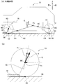
- 1A is a schematic diagram of the vehicle shown in FIG. 1 and includes an in-wheel motor only on the front wheels
- FIG. 1B shows the component force of the input load from the protrusions on the front wheels of the vehicle shown in FIG. It is a schematic diagram shown.
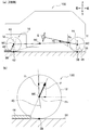
- (A) is a schematic diagram of the vehicle which concerns on a comparative example
- (b) is a schematic diagram which shows the component force of the input load from a protrusion in the front wheel of the vehicle which concerns on the comparative example shown to (a).
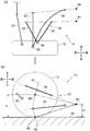
- (A) is a schematic plan view applied to a double wishbone suspension as a front suspension for the left front wheel
- (b) is a side view seen from the direction of arrow A in (a).
- FIG. 1 is a partially enlarged side view of a vehicle according to an embodiment of the present invention.
- “front and rear” indicates the vehicle longitudinal direction
- “left and right” indicates the vehicle lateral direction (vehicle width direction)
- “up and down” indicates the vertical vertical direction.
- the vehicle 10 includes a wheel (front wheel) 12, an in-wheel motor 14, and a front suspension 16.
- the vehicle 10 includes left and right wheels 12 and 12, left and right in-wheel motors 14 and 14, and left and right front suspensions 16 and 16, respectively. Is omitted.
- the in-wheel motor 14 includes an electric motor 20 that has a motor shaft 18 and drives the wheels 12, and a transmission mechanism 22 that transmits the driving force of the electric motor 20 to the wheels 12.
- the in-wheel motor 14 is disposed under the spring.
- the transmission mechanism 22 transmits the driving force of the electric motor 20 to the output shaft 26 of the wheel 12 via the transmission shaft 24.
- the output shaft 26 has the wheel center (WC) of the wheel 12.
- the front suspension 16 has a knuckle 28 that rotatably supports the wheel 12 and suspension arms (not shown) such as a lower arm and an upper arm.
- a compliance bush 31 is disposed below the wheel center (WC) of the wheel 12 and on the vehicle body side in front of the vehicle.
- the knuckle 28 has a lower arm joint 30 disposed substantially below the wheel center (WC) of the wheel 12 and a tie rod joint 32 disposed below the lower arm joint 30 on the lower side of the wheel center (WC) of the wheel 12.
- an upper arm joint 34 disposed substantially above the wheel center (WC) of the wheel 12.
- the compliance bush 31 includes, for example, a vibration-proof bush, and includes an inner cylinder and an outer cylinder, and a cylindrical rubber elastic body that is sandwiched between the inner cylinder and the outer cylinder.
- the compliance bush 31 absorbs the force received in the vehicle front-rear direction and increases the front-rear compliance (elastic force).
- the operating point of the driving force (F1) transmitted from the in-wheel motor 14 is a grounding point between the wheel 12 and the road surface 36. 38 (see FIG. 1).
- the point of action of the braking force (F2) is the same as the point of action of the driving force (F1), and becomes the contact point 38 between the wheel 12 and the road surface 36.
- the directions of the driving force (F1) and the braking force (F2) are opposite to each other.
- the point of action of the driving force (F1) and the point of action of the braking force (F2) are the same at the ground point 38, so the anti-dive angle ( ⁇ 1) of the anti-dive geometry and This will be described below using the anti-lift angle ( ⁇ 2).
- the left and right front wheels 12 are respectively provided with in-wheel motors 14 and applied to a front drive type vehicle or a four-wheel drive vehicle.
- the vehicle 10 is not limited to four wheels, and may be, for example, six wheels (a front wheel that is positioned most forward of the vehicle is provided with an in-wheel motor).
- a vehicle an on-board engine / front drive type vehicle or an on-board engine / In the wheel drive vehicle
- the wheel center (WC) of the front wheel 12 is the point of action of the drive force.
- FIG. 2A is a schematic diagram of the vehicle shown in FIG. 1 having an in-wheel motor only on the front wheels
- FIG. 2B is an input load from a protrusion on the front wheel of the vehicle shown in FIG.
- It is a schematic diagram which shows the component force. 2 (a) and 2 (b), the wheel 12 is described as being divided into a front wheel 12 and a rear wheel 12, respectively, and the same reference numerals are used for those common between the front wheel 12 and the rear wheel 12. Is used.
- the wheel center (WC) of the front wheel 12 and the front contact point 38 are predetermined with respect to a virtual rotation center (RC; Rotation Center) located at the lowermost end of the vehicle body and on the front side of the vehicle. It is provided so as to be rotatable by an angle. Due to the displacement (stroke) of the front suspension 16, an arcuate locus 40 (see FIGS. 2A and 2B) of the wheel center (WC) of the front wheel 12 is formed, and a circle at the front grounding point 38 is formed. An arcuate locus 42 (see FIG. 2A) is formed. A sprung vehicle body pitching center point (Pc) is provided on an extension line connecting the front grounding point 38 and the virtual rotation center (RC). Further, G indicates the center of gravity of the sprung vehicle body.
- RC Rotation Center
- the anti-dive angle ( ⁇ 1) of the front suspension 16 forms an angle toward the upper side of the vehicle with respect to a horizontal line (same as a straight line along the road surface 36) from the contact point 38 of the front wheel 12 toward the rear of the vehicle. ) Is set.
- the “anti-dive angle” is an angle formed between a straight line connecting the ground point 38 and the virtual rotation center (RC) of the ground point 38 accompanying the displacement of the front suspension 16 and a horizontal line of the ground point 38 ( ⁇ 1).
- the anti-lift angle ( ⁇ 2) of the rear suspension is set so as to form an angle toward the upper side of the vehicle with respect to a horizontal line from the contact point 38 of the rear wheel 12 toward the front of the vehicle.
- the arc-shaped locus 40 of the wheel center (WC) of the front wheel 12 due to the displacement (stroke) of the front suspension 16 is as follows. And it is set so that it may extend toward the vehicle rear. In other words, the extending direction of the arc-shaped locus 40 of the wheel center (WC) formed by the displacement of the front suspension 16 is not in the upward direction and the vehicle front direction, but in the arc shape in the vehicle upper direction and the vehicle rear direction. Is set to move.
- the wheel center (WC) of the rear wheel 12 and the rear contact point 38 are provided so as to be rotatable by a predetermined angle around the rear virtual rotation center (RC) disposed on the rear side of the vehicle body. Due to the displacement (stroke) of the rear suspension, an arcuate locus 44 of the wheel center (WC) of the rear wheel 12 is formed, and an arcuate locus 46 of the rear contact point 38 is formed.
- a sprung vehicle body pitching center point (Pc) is provided on an extension line connecting the wheel center (WC) of the rear wheel 12 and the virtual rotation center (RC) of the rear.
- the vehicle 10 according to the present embodiment is basically configured as described above. Next, the effects of the vehicle 10 according to the present embodiment will be described while comparing with the vehicle 100 according to the comparative example.
- FIG. 3A is a schematic diagram of a vehicle according to a comparative example
- FIG. 3B is a schematic diagram illustrating a component force of an input load from a protrusion in the front wheel of the vehicle according to the comparative example illustrated in FIG. FIG. It should be noted that the same components as those in the present embodiment are denoted by the same reference numerals and will be described below.
- the vehicle 100 according to the comparative example is an on-board engine / front drive type vehicle in which a drive source is disposed on a spring.
- the wheel center (WC) of the front wheel 12 serves as an action point of the drive force (F1), and the ground point 38 serves as the drive source (F1).
- the front virtual rotation center (RC) is disposed at a position above the lowermost end of the vehicle body and from the center of the vehicle body.
- the sprung vehicle body pitching center point (Pc) is located behind the vehicle body.
- the arc-shaped locus 40 of the wheel center (WC) of the front wheel 12 is formed so as to extend substantially upward from the lower side. Has been.
- an input load (F) is applied to the front wheel 12 by the protrusion 48 of the road surface 36. Is done.
- the input load (F) is decomposed into a horizontal component force (Fh) and a tangential component force (Ft) of the wheel center locus.
- the horizontal component force Fh in the vehicle 10 according to the present embodiment is smaller than that of the vehicle 100 according to the comparative example.
- the horizontal component force Fh is larger than that in the present embodiment, the impact due to the force that pulls the vehicle body toward the rear of the vehicle is increased, and the time when the projection 48 is passed over. Ride comfort is reduced.
- the spring rate of the front suspension 16 of this embodiment and a comparative example shall be the same.
- FIG. 4A is a schematic plan view applied to a double wishbone suspension as a front suspension for the left front wheel
- FIG. 4B is a side view seen from the direction of the arrow A in FIG.
- reference numeral 50 is a lower arm
- reference numeral 52 is an upper arm
- reference numeral 54 is a tie rod
- reference numeral 56 is an upper arm joint
- reference numeral 58 is a lower arm joint.
- alternate long and short dash lines 60 indicate vehicle bodies (for example, subframes), respectively.
- the vertical height (H1) of the wheel center (WC) and the virtual rotation center (RC) of the ground contact point 38 as viewed from the side of the vehicle body.
- H1 the vertical height of the wheel center (WC) and the virtual rotation center (RC) of the ground contact point 38 as viewed from the side of the vehicle body.
- it is characterized in that it is set higher than the ground contact point 38 and lower than the height (H) of the wheel center (WC) (0 ⁇ H1 ⁇ H).
- the height (H1) of the wheel center (WC) and the virtual rotation center (RC) of the ground contact point 38 is set to be equal to or less than the height (H) of the wheel center (WC).
- the double wishbone suspension 62 is used as the applicable front suspension 16, the present invention is not limited to this and may be applied to, for example, a multilink suspension.
- the arc-shaped locus 40 of the wheel center (WC) due to the displacement of the front suspension 16 is set so as to be movable upward and backward of the vehicle, so that the projection 48 on the road surface 36 causes the front wheel 12 to move.
- the horizontal component force (Fh) of the input load (F) is reduced, and the ride comfort can be improved by mitigating the impact when riding over the unevenness.
- the height (H1) of the virtual rotation center (RC) in the vertical vertical direction is set to be higher than the ground contact point 38 and lower than the height (H) of the wheel center (WC).
- the arc-shaped locus 40 of the wheel center (WC) due to the displacement of the suspension 16 can be the vehicle upper side and the vehicle rear side.
- the horizontal component force (Fh) generated on the front wheel 12 by the protrusion 48 of the road surface 36 is reduced as compared with the vehicle 100 according to the comparative example having the drive source on the spring of the front suspension 16. (See FIG. 2 (b) and FIG. 3 (b) for comparison).
- the input load (F) by the protrusion 48 of the road surface 36 is applied, the force for pulling the vehicle body toward the rear of the vehicle is reduced, and the impact at the time of riding over the unevenness is alleviated and the ride comfort is improved. Can be improved.
Landscapes
- Engineering & Computer Science (AREA)
- Mechanical Engineering (AREA)
- Chemical & Material Sciences (AREA)
- Combustion & Propulsion (AREA)
- Transportation (AREA)
- Vehicle Body Suspensions (AREA)
- Arrangement Or Mounting Of Propulsion Units For Vehicles (AREA)
Abstract
Priority Applications (4)
| Application Number | Priority Date | Filing Date | Title |
|---|---|---|---|
| US15/747,960 US10464388B2 (en) | 2015-07-30 | 2016-07-11 | Vehicle in-wheel motor suspension |
| JP2017531120A JP6505842B2 (ja) | 2015-07-30 | 2016-07-11 | 車両 |
| DE112016003440.7T DE112016003440T5 (de) | 2015-07-30 | 2016-07-11 | Fahrzeug |
| CN201680043609.4A CN107848351B (zh) | 2015-07-30 | 2016-07-11 | 车辆 |
Applications Claiming Priority (2)
| Application Number | Priority Date | Filing Date | Title |
|---|---|---|---|
| JP2015150199 | 2015-07-30 | ||
| JP2015-150199 | 2015-07-30 |
Publications (1)
| Publication Number | Publication Date |
|---|---|
| WO2017018180A1 true WO2017018180A1 (fr) | 2017-02-02 |
Family
ID=57884597
Family Applications (1)
| Application Number | Title | Priority Date | Filing Date |
|---|---|---|---|
| PCT/JP2016/070372 Ceased WO2017018180A1 (fr) | 2015-07-30 | 2016-07-11 | Véhicule |
Country Status (5)
| Country | Link |
|---|---|
| US (1) | US10464388B2 (fr) |
| JP (1) | JP6505842B2 (fr) |
| CN (1) | CN107848351B (fr) |
| DE (1) | DE112016003440T5 (fr) |
| WO (1) | WO2017018180A1 (fr) |
Cited By (1)
| Publication number | Priority date | Publication date | Assignee | Title |
|---|---|---|---|---|
| WO2025046836A1 (fr) * | 2023-08-31 | 2025-03-06 | 三菱自動車工業株式会社 | Dispositif de commande de freinage |
Families Citing this family (5)
| Publication number | Priority date | Publication date | Assignee | Title |
|---|---|---|---|---|
| DE102019105566B4 (de) * | 2019-03-05 | 2023-01-05 | Benteler Automobiltechnik Gmbh | Fahrwerksanordnung für ein Kraftfahrzeug sowie Verfahren zum Betreiben eines Kraftfahrzeuges |
| DE102019214083B4 (de) * | 2019-09-16 | 2024-07-25 | Robert Bosch Gmbh | Verfahren und Steuereinheit zum Heben und/oder Senken eines Fahrgestells sowie Fahrgestell |
| JP7178437B2 (ja) * | 2021-03-10 | 2022-11-25 | 本田技研工業株式会社 | 車両 |
| JP2023068985A (ja) * | 2021-11-04 | 2023-05-18 | ヤマハ発動機株式会社 | 車両 |
| FI20235333A1 (en) * | 2023-03-22 | 2024-09-23 | 18 Wheels Oy | Suspension arrangements for vehicles and electric vehicles |
Citations (4)
| Publication number | Priority date | Publication date | Assignee | Title |
|---|---|---|---|---|
| JPH1142918A (ja) * | 1997-07-25 | 1999-02-16 | Nissan Motor Co Ltd | サスペンション装置 |
| JP2000006626A (ja) * | 1998-06-18 | 2000-01-11 | Nissan Motor Co Ltd | ストラット式サスペンション |
| JP2008201291A (ja) * | 2007-02-21 | 2008-09-04 | Advics:Kk | 車両挙動制御装置 |
| JP2011031739A (ja) * | 2009-07-31 | 2011-02-17 | Nissan Motor Co Ltd | サスペンション制御装置、及びサスペンション制御方法 |
Family Cites Families (29)
| Publication number | Priority date | Publication date | Assignee | Title |
|---|---|---|---|---|
| DE4340557C2 (de) * | 1993-11-29 | 1995-09-28 | Porsche Ag | Radaufhängung |
| CN1684851B (zh) * | 2002-08-29 | 2010-05-05 | 株式会社普利司通 | 轮内马达系统 |
| JP4139353B2 (ja) * | 2004-05-25 | 2008-08-27 | トヨタ自動車株式会社 | 車輪支持装置 |
| US20070272458A1 (en) * | 2004-12-09 | 2007-11-29 | Kabushikikaisha Equos Research | Wheel Supporting and Driving Device |
| FR2890902B1 (fr) * | 2005-09-22 | 2007-12-14 | Peugeot Citroen Automobiles Sa | Dispositif de commande de suspension, vehicule muni de celui-ci, procede d'obtention et programme |
| JP4887771B2 (ja) * | 2005-12-12 | 2012-02-29 | トヨタ自動車株式会社 | 走行装置 |
| US7849945B2 (en) * | 2006-02-24 | 2010-12-14 | Honda Motor Co., Ltd | Modular electric powertrain for a vehicle |
| US8132636B2 (en) | 2006-03-08 | 2012-03-13 | Ntn Corporation | In-wheel motor drive unit |
| JP4820189B2 (ja) * | 2006-03-09 | 2011-11-24 | 本田技研工業株式会社 | 車両用ホイール駆動装置の配置構造 |
| JP4360376B2 (ja) * | 2006-03-31 | 2009-11-11 | トヨタ自動車株式会社 | 車両用駆動輪構造 |
| US7734384B2 (en) * | 2006-09-05 | 2010-06-08 | Ford Global Technologies, Llc | Tuned battery pack damper for a hybrid electric vehicle |
| DE102007051971B4 (de) * | 2007-10-31 | 2010-09-16 | Audi Ag | Stellvorrichtung für Federungseinrichtungen |
| JP4968005B2 (ja) * | 2007-11-13 | 2012-07-04 | トヨタ自動車株式会社 | サスペンション制御装置 |
| JP5325653B2 (ja) * | 2009-05-19 | 2013-10-23 | 東海ゴム工業株式会社 | 電動モータ駆動式車両用の駆動ユニット防振保持装置 |
| GB2479431B (en) * | 2011-03-01 | 2012-08-08 | Protean Electric Ltd | A suspension control system |
| JP2013095309A (ja) * | 2011-11-02 | 2013-05-20 | Ntn Corp | インホイールモータ車両用サスペンションシステム |
| US8985594B2 (en) * | 2012-01-11 | 2015-03-24 | Toyota Jidosha Kabushiki Kaisha | Vehicle |
| JP2013241075A (ja) * | 2012-05-18 | 2013-12-05 | Hitachi Automotive Systems Ltd | サスペンション制御装置 |
| JP5962559B2 (ja) | 2013-03-22 | 2016-08-03 | トヨタ自動車株式会社 | 車両挙動制御装置 |
| DE102014204519A1 (de) * | 2013-04-08 | 2014-10-09 | Ford Global Technologies, Llc | Vorrichtung und Verfahren zur proaktiven Steuerung eines Schwingungsdämpfungssystems eines Fahrzeugs |
| JP6136640B2 (ja) * | 2013-06-27 | 2017-05-31 | スズキ株式会社 | フロントサスペンション装置 |
| JP2015104966A (ja) * | 2013-11-29 | 2015-06-08 | トヨタ自動車株式会社 | 車両のサスペンション装置 |
| JP6107689B2 (ja) * | 2014-02-05 | 2017-04-05 | トヨタ自動車株式会社 | 車両 |
| CN103921637B (zh) * | 2014-04-29 | 2016-05-11 | 重庆大学 | 高速电动轮轮内减振装置及电动车轮 |
| EP3157771B1 (fr) * | 2014-06-18 | 2019-08-07 | Volvo Construction Equipment AB | Procédé permettant de déterminer si oui ou non une perte de contact avec le sol est imminente pour une roue d'un véhicule |
| US9914348B2 (en) * | 2014-06-30 | 2018-03-13 | Nissan North America, Inc. | Electric drive motor assembly for a wheel |
| GB2528065B (en) * | 2014-07-08 | 2018-07-04 | Jaguar Land Rover Ltd | Vehicle suspension systems |
| DE102014011110B4 (de) * | 2014-07-26 | 2021-03-18 | Audi Ag | Vorrichtung zum Verstellen von Sturz und/oder Spur eines Fahrzeugrads mit Drehmomentübertragungselement |
| DE102014011193B4 (de) * | 2014-07-26 | 2021-03-18 | Audi Ag | Vorrichtung zum Verstellen von Sturz und/oder Spur eines Fahrzeugrads mit einer Bremsmomentabstützung |
-
2016
- 2016-07-11 WO PCT/JP2016/070372 patent/WO2017018180A1/fr not_active Ceased
- 2016-07-11 US US15/747,960 patent/US10464388B2/en active Active
- 2016-07-11 CN CN201680043609.4A patent/CN107848351B/zh not_active Expired - Fee Related
- 2016-07-11 JP JP2017531120A patent/JP6505842B2/ja not_active Expired - Fee Related
- 2016-07-11 DE DE112016003440.7T patent/DE112016003440T5/de not_active Withdrawn
Patent Citations (4)
| Publication number | Priority date | Publication date | Assignee | Title |
|---|---|---|---|---|
| JPH1142918A (ja) * | 1997-07-25 | 1999-02-16 | Nissan Motor Co Ltd | サスペンション装置 |
| JP2000006626A (ja) * | 1998-06-18 | 2000-01-11 | Nissan Motor Co Ltd | ストラット式サスペンション |
| JP2008201291A (ja) * | 2007-02-21 | 2008-09-04 | Advics:Kk | 車両挙動制御装置 |
| JP2011031739A (ja) * | 2009-07-31 | 2011-02-17 | Nissan Motor Co Ltd | サスペンション制御装置、及びサスペンション制御方法 |
Cited By (1)
| Publication number | Priority date | Publication date | Assignee | Title |
|---|---|---|---|---|
| WO2025046836A1 (fr) * | 2023-08-31 | 2025-03-06 | 三菱自動車工業株式会社 | Dispositif de commande de freinage |
Also Published As
| Publication number | Publication date |
|---|---|
| JPWO2017018180A1 (ja) | 2018-02-22 |
| CN107848351B (zh) | 2020-07-17 |
| US20180222272A1 (en) | 2018-08-09 |
| CN107848351A (zh) | 2018-03-27 |
| JP6505842B2 (ja) | 2019-04-24 |
| US10464388B2 (en) | 2019-11-05 |
| DE112016003440T5 (de) | 2018-05-03 |
Similar Documents
| Publication | Publication Date | Title |
|---|---|---|
| JP6505842B2 (ja) | 車両 | |
| JP4207075B2 (ja) | インホイールモータ車 | |
| US20180334001A1 (en) | Suspension device for non-steered driving wheel incorporating in-wheel motor | |
| US8398092B2 (en) | Active roll control system for vehicle | |
| JP6091791B2 (ja) | アクティブロールコントロール装置 | |
| WO2017086403A1 (fr) | Véhicule | |
| US10556474B2 (en) | Front suspension structure of automotive vehicle | |
| KR102617278B1 (ko) | 액티브 롤 컨트롤 장치 | |
| KR20220068550A (ko) | 독립 현가 시스템 | |
| JP6365008B2 (ja) | 車両用懸架装置 | |
| CN108215688B (zh) | 用于车辆的悬架系统 | |
| JP6061724B2 (ja) | 自動三輪車とそのロール減衰装置 | |
| JP7569535B2 (ja) | 車輪モジュール | |
| JP4370518B2 (ja) | 自動車のフロントサスペンション装置 | |
| CN115703506A (zh) | 独立转向系统 | |
| JP4664796B2 (ja) | 操舵輪用サスペンション装置 | |
| CN114801619A (zh) | 多连杆悬架装置以及车辆 | |
| JP5355189B2 (ja) | サスペンション装置 | |
| JP7850370B2 (ja) | 車両のサスペンション装置 | |
| CN207328021U (zh) | 一种机动车的车轮独立悬挂减震结构 | |
| KR100461608B1 (ko) | 차량용 차축 현가장치의 롤 방지구조 | |
| JP2012111250A (ja) | 車両用懸架装置および車両の制動偏向抑制方法 | |
| WO2020075646A1 (fr) | Structure de suspension pour dispositif d'entraînement de moteur-roue | |
| KR20200060848A (ko) | 자동차용 커플드 토션 빔 액슬 | |
| KR20090049200A (ko) | 자동차의 현가장치 |
Legal Events
| Date | Code | Title | Description |
|---|---|---|---|
| 121 | Ep: the epo has been informed by wipo that ep was designated in this application |
Ref document number: 16830285 Country of ref document: EP Kind code of ref document: A1 |
|
| ENP | Entry into the national phase |
Ref document number: 2017531120 Country of ref document: JP Kind code of ref document: A |
|
| WWE | Wipo information: entry into national phase |
Ref document number: 15747960 Country of ref document: US |
|
| WWE | Wipo information: entry into national phase |
Ref document number: 112016003440 Country of ref document: DE |
|
| 122 | Ep: pct application non-entry in european phase |
Ref document number: 16830285 Country of ref document: EP Kind code of ref document: A1 |