WO2017018201A1 - Procédé de soudage de plaque en acier plaquée de zinc - Google Patents
Procédé de soudage de plaque en acier plaquée de zinc Download PDFInfo
- Publication number
- WO2017018201A1 WO2017018201A1 PCT/JP2016/070530 JP2016070530W WO2017018201A1 WO 2017018201 A1 WO2017018201 A1 WO 2017018201A1 JP 2016070530 W JP2016070530 W JP 2016070530W WO 2017018201 A1 WO2017018201 A1 WO 2017018201A1
- Authority
- WO
- WIPO (PCT)
- Prior art keywords
- welding
- less
- galvanized steel
- steel sheet
- pulse peak
- Prior art date
- Legal status (The legal status is an assumption and is not a legal conclusion. Google has not performed a legal analysis and makes no representation as to the accuracy of the status listed.)
- Ceased
Links
Images

Classifications
-
- B—PERFORMING OPERATIONS; TRANSPORTING
- B23—MACHINE TOOLS; METAL-WORKING NOT OTHERWISE PROVIDED FOR
- B23K—SOLDERING OR UNSOLDERING; WELDING; CLADDING OR PLATING BY SOLDERING OR WELDING; CUTTING BY APPLYING HEAT LOCALLY, e.g. FLAME CUTTING; WORKING BY LASER BEAM
- B23K9/00—Arc welding or cutting
- B23K9/16—Arc welding or cutting making use of shielding gas
-
- B—PERFORMING OPERATIONS; TRANSPORTING
- B23—MACHINE TOOLS; METAL-WORKING NOT OTHERWISE PROVIDED FOR
- B23K—SOLDERING OR UNSOLDERING; WELDING; CLADDING OR PLATING BY SOLDERING OR WELDING; CUTTING BY APPLYING HEAT LOCALLY, e.g. FLAME CUTTING; WORKING BY LASER BEAM
- B23K9/00—Arc welding or cutting
- B23K9/09—Arrangements or circuits for arc welding with pulsed current or voltage
-
- B—PERFORMING OPERATIONS; TRANSPORTING
- B23—MACHINE TOOLS; METAL-WORKING NOT OTHERWISE PROVIDED FOR
- B23K—SOLDERING OR UNSOLDERING; WELDING; CLADDING OR PLATING BY SOLDERING OR WELDING; CUTTING BY APPLYING HEAT LOCALLY, e.g. FLAME CUTTING; WORKING BY LASER BEAM
- B23K9/00—Arc welding or cutting
- B23K9/23—Arc welding or cutting taking account of the properties of the materials to be welded
-
- B—PERFORMING OPERATIONS; TRANSPORTING
- B23—MACHINE TOOLS; METAL-WORKING NOT OTHERWISE PROVIDED FOR
- B23K—SOLDERING OR UNSOLDERING; WELDING; CLADDING OR PLATING BY SOLDERING OR WELDING; CUTTING BY APPLYING HEAT LOCALLY, e.g. FLAME CUTTING; WORKING BY LASER BEAM
- B23K9/00—Arc welding or cutting
- B23K9/09—Arrangements or circuits for arc welding with pulsed current or voltage
- B23K9/091—Arrangements or circuits for arc welding with pulsed current or voltage characterised by the circuits
-
- B—PERFORMING OPERATIONS; TRANSPORTING
- B23—MACHINE TOOLS; METAL-WORKING NOT OTHERWISE PROVIDED FOR
- B23K—SOLDERING OR UNSOLDERING; WELDING; CLADDING OR PLATING BY SOLDERING OR WELDING; CUTTING BY APPLYING HEAT LOCALLY, e.g. FLAME CUTTING; WORKING BY LASER BEAM
- B23K9/00—Arc welding or cutting
- B23K9/09—Arrangements or circuits for arc welding with pulsed current or voltage
- B23K9/091—Arrangements or circuits for arc welding with pulsed current or voltage characterised by the circuits
- B23K9/092—Arrangements or circuits for arc welding with pulsed current or voltage characterised by the circuits characterised by the shape of the pulses produced
-
- B—PERFORMING OPERATIONS; TRANSPORTING
- B23—MACHINE TOOLS; METAL-WORKING NOT OTHERWISE PROVIDED FOR
- B23K—SOLDERING OR UNSOLDERING; WELDING; CLADDING OR PLATING BY SOLDERING OR WELDING; CUTTING BY APPLYING HEAT LOCALLY, e.g. FLAME CUTTING; WORKING BY LASER BEAM
- B23K9/00—Arc welding or cutting
- B23K9/10—Other electric circuits therefor; Protective circuits; Remote controls
- B23K9/1006—Power supply
-
- B—PERFORMING OPERATIONS; TRANSPORTING
- B23—MACHINE TOOLS; METAL-WORKING NOT OTHERWISE PROVIDED FOR
- B23K—SOLDERING OR UNSOLDERING; WELDING; CLADDING OR PLATING BY SOLDERING OR WELDING; CUTTING BY APPLYING HEAT LOCALLY, e.g. FLAME CUTTING; WORKING BY LASER BEAM
- B23K9/00—Arc welding or cutting
- B23K9/16—Arc welding or cutting making use of shielding gas
- B23K9/173—Arc welding or cutting making use of shielding gas and of a consumable electrode
-
- B—PERFORMING OPERATIONS; TRANSPORTING
- B23—MACHINE TOOLS; METAL-WORKING NOT OTHERWISE PROVIDED FOR
- B23K—SOLDERING OR UNSOLDERING; WELDING; CLADDING OR PLATING BY SOLDERING OR WELDING; CUTTING BY APPLYING HEAT LOCALLY, e.g. FLAME CUTTING; WORKING BY LASER BEAM
- B23K2101/00—Articles made by soldering, welding or cutting
- B23K2101/34—Coated articles ; Surface treated articles
-
- B—PERFORMING OPERATIONS; TRANSPORTING
- B23—MACHINE TOOLS; METAL-WORKING NOT OTHERWISE PROVIDED FOR
- B23K—SOLDERING OR UNSOLDERING; WELDING; CLADDING OR PLATING BY SOLDERING OR WELDING; CUTTING BY APPLYING HEAT LOCALLY, e.g. FLAME CUTTING; WORKING BY LASER BEAM
- B23K2103/00—Materials to be soldered, welded or cut
- B23K2103/02—Iron or ferrous alloys
- B23K2103/04—Steel or steel alloys
Definitions
- the present invention relates to a welding method used for automobile parts and the like, and more particularly, to a welding method for a galvanized steel sheet used in a part where corrosion resistance is important and a galvanized steel sheet is used.
- galvanized steel sheets with high corrosion resistance may be used for undercarriage parts related to wheels, which are automobile parts, and lower parts of parts that face the road surface in the vehicle body.
- a suspension member or suspension arm which is an underbody part of an automobile, uses a galvanized steel sheet.
- the galvanized steel plate used is often subjected to welding, and is coated after the welding.
- Patent Document 1 the welding current waveform is controlled, the carbon dioxide concentration of the shielding gas is set to be high, and the welding current is swung by repeating the high and low periods of the pulse current, thereby discharging zinc vapor. It is described to be performed while promoting.
- Patent Document 2 describes that, in a galvanized steel sheet, welding is performed at high speed by periodically repeating a period in which a rectangular wave pulse is applied and a period in which only a base current is applied.
- the conventional galvanized steel sheet welding method has the following problems.
- a power source capable of special waveform control is required, and versatility is impaired.
- an increase in the amount of CO 2 in the shielding gas causes an increase in the amount of slag produced, and the slag that is difficult to be applied increases, so that the electrodeposition paintability deteriorates.
- a long base period is set with respect to the plate thickness, so that magnetic blowing is likely to occur.
- the arc tends to become unstable and causes pore defects.
- spatter is likely to occur due to the instability of the arc, and the attached portion is easily rusted and causes deterioration of the coating.
- the present invention was devised in view of the above-described problems, and a general-purpose welding apparatus can be used.
- the amount of carbonic acid gas in the shield gas is suppressed, and the electrodeposition coating property and the pore resistance are improved. It is an object of the present invention to provide a welding method for a galvanized steel sheet.
- the galvanized steel sheet welding method has the following configuration. That is, the welding method of the galvanized steel sheet uses pulse welding in which a pulse peak current and a base current are repeatedly applied, a welding speed is set to 100 cm / min or less, and Ar contains 1% by volume to 10% by volume of CO 2 and A welding method for a galvanized steel sheet using a shield gas to which at least one of O 2 is added, wherein the pulse peak time of the pulse peak current is 7% or more of one cycle according to the plate thickness of the galvanized steel sheet.
- the lower limit value of the pulse peak time when the plate thickness is 0.8 mm or more and less than 1.6 mm is 7% or more of the one cycle, and the upper limit value of the pulse peak time is less than 50%.
- the lower limit value of the pulse peak time when the plate thickness is less than 15 mm and less than 2.3 mm is 15% or more of the one cycle,
- the upper limit value of the pulse peak time is less than 30% of the one cycle, and the lower limit value of the pulse peak time when the plate thickness is 2.3 mm or more and less than 3 mm is 20% or more of the one cycle,
- the upper limit value of the pulse peak time is 40% of the one period.
- the pore resistance is improved. Furthermore, since the ratio of the period in which the arc is strengthened according to the plate thickness is optimized in one cycle, the pore resistance can be stably improved. Moreover, the amount of slag generated in the welded portion can be suppressed to a very small amount by setting the concentration of the oxidizing gas such as CO 2 or O 2 to 10% or less.
- the shielding gas it was decided CO 2 or O 2 is less than 8 wt%. With this procedure, the amount of slag generated in the welded portion can be further suppressed in the method for welding galvanized steel sheets.
- the welding wire diameter is 0.8 mm or more and 1.2 mm or less
- the plate thickness is 1.6 mm or more and less than 2.3 mm.
- the welding wire diameter is 1.0 mm to 1.4 mm and the welding wire diameter is 1.2 mm to 1.6 mm when the plate thickness is 2.3 mm or more.
- the welding wire diameter is welded in a predetermined range according to the plate thickness, so that the gap resistance is given priority to the welding with a thin plate thickness, and is thick. Pole resistance is given priority for welding with plate thickness.
- the welding speed of the said pulse welding shall be 100 cm / min or less, Preferably it shall be 75 cm / min or less. In addition, it is preferable that the lower limit of welding speed is 30 cm / min or more. According to such a procedure, in the welding method of the galvanized steel sheet, the gap resistance and the porosity resistance corresponding to the plate thickness can be reliably realized by making the welding speed slower than the welding speed normally performed.
- the basis weight of the galvanized steel sheet welded by pulse welding is 90 g / m 2 or less on one side.
- the welding method for galvanized steel sheets restricts the welding conditions more restrictively, making it easier for zinc vapor to escape from the welded part, preventing the arc from coming off the welded part while improving the porosity. In addition, it is possible to suppress spatter.
- the pulse peak time is set to be a predetermined value of one cycle in pulse welding corresponding to the plate thickness, so that zinc vapor is not easily taken into the welded portion.
- the pore resistance is improved.
- the amount of slag generated in the welded portion can be suppressed to a very small amount by setting the concentration of the oxidizing gas to 10% or less, the paintability can be improved.
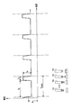
- the welding method which concerns on this invention it is a schematic diagram which shows typically the relationship between a pulse peak time and a pulse peak current corresponding to a graph.
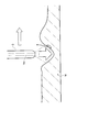
- It is sectional drawing which shows typically the state which escapes the zinc vapor
- a procedure of using the pulse welding apparatus 1 for a method for welding a galvanized steel sheet according to the present invention (hereinafter referred to as a welding method) will be described with reference to the drawings.
- a welding method a procedure of using the pulse welding apparatus 1 for a method for welding a galvanized steel sheet according to the present invention
- This welding method uses the welding apparatus 1 to set a pulse peak time corresponding to the plate thickness of the galvanized steel sheet W, and uses a welding wire and a shield gas to perform pulse welding.
- a solid wire YA is used as a welding wire
- a shielding gas which is an Ar mixed gas (Ar—CO 2 gas, Ar—O 2 gas, Ar—CO 2 —O 2 gas) is supplied, and the solid wire is supplied.
- a pulse current which is a welding current
- an arc is generated between the solid wire YA and the galvanized steel sheet W, which is a base material, to perform welding.
- the galvanized steel sheet W to be welded is, for example, a suspension member used as an undercarriage part of an automobile.
- a suspension member a steel plate with a predetermined thickness and a galvanized shape is used.
- the galvanized steel sheet W used here one having a basis weight of 90 g / m 2 or less is used as an example.
- the galvanized steel sheet W may be SGCC (hot dip galvanized steel sheet) in accordance with JIS G 3302: 2010, and the basis weight of galvanization may be 45 g / m 2 which is 50 g / m 2 or less.
- the basis weight may be 90 g / m 2 or less.
- a galvanized steel sheet W having a thickness in the range of 0.8 to 2.6 mm is used.
- This galvanized steel plate W is a plate material in which a galvanized film is formed on the surface of the steel plate, and the composition, thickness, etc. of the steel plate are not particularly limited.
- the basis weight of the galvanized steel sheet W with respect to the base material surface is not particularly limited as long as it is 90 g / m 2 or less. If the basis weight of the galvanized steel sheet W exceeds 90 g / m 2 , the discharge of zinc vapor cannot be promoted during welding, which makes it difficult to suppress pores in the welded portion. Note that the galvanized steel sheet W is assumed to have a thickness in the range of 0.8 to 4.0 mm.
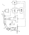
- the welding apparatus 1 includes a robot arm 2 having a multi-joint, a robot controller 10 that controls the operation of the robot arm 2, a teaching device 20 that is an operation device, and a welding wire (solid wire, flux cored wire, metal cored).
- a wire or the like) includes a feeding mechanism Sd for feeding YA and a welding power source G for performing welding work.
- this welding apparatus 1 is an example, and if the connection hose from the gas cylinder Bg which supplies shield gas is comprised so that connection is possible, and if it is an apparatus which can perform general pulse welding, the structure will be specifically limited. It is not something.
- the feeding mechanism Sd is configured separately from the robot arm 2, but may be configured to be integrally installed at a predetermined position of the robot arm 2.
- a welding wire YA is fed to a welding torch 3 attached to the tip of a robot arm 2, and a pulse gas and a base current supplied from a welding power source G, a shield gas supplied from a gas cylinder Bg, etc. Welding is performed according to welding conditions such as.
- the pulse peak time is set based on the thickness of the galvanized steel sheet W to be welded.
- the pulse peak time is set to a predetermined range based on the thickness of the galvanized steel sheet W, and data of the set predetermined range is set to the robot controller.
- the pulse peak time is 7% or more and less than 50% of one cycle, preferably 7% of one cycle. It is set within the range of 40% or less.
- the ratio of the pulse peak time to one cycle may be simply expressed as “peak ratio”.
- Ip is a pulse peak current
- Ib is a pulse base current
- Tp is a pulse peak time
- Tb is a pulse base time
- Tpulse is a time of one pulse period.
- the pulse peak time (Tp) is set to 7% or more and less than 15% with respect to one cycle time (Tpulse).
- the pulse peak time (Tp) is set to 15% or more and less than 30% with respect to one cycle time (Tpulse).
- pulse peak time (Tp) is set as 20% or more and 40% or less with respect to time (Tpulse) of 1 period. Furthermore, when the plate thickness of the galvanized steel sheet W is 2.6 mm, the pulse peak time (Tp) is set to 20% or more and 40% or less with respect to one cycle time (Tpulse).
- the pulse peak time (Tp) for each thickness of the galvanized steel sheet W is less than each lower limit value of the ratio to one cycle time (Tpulse)
- the pulse base time is too long, so that It becomes easy to occur and the arc force acting on the molten pool becomes insufficient, the pushing of the molten pool by the arc force becomes weak, and zinc (Zn) vapor is taken into the molten pool and pores (defects) are generated.
- the ratio of the pulse peak time (Tp) to each plate thickness of the galvanized steel sheet W described above with respect to one cycle time (Tpulse) exceeds each upper limit value, the droplets are stably transferred to the molten pool. The amount of spatter increases.
- the pulse peak time is accurately within the predetermined range (7% or more and less than 50%: preferably, based on the thickness) 7% or more and 40% or less) to improve the porosity resistance.
- the range where the pulse peak time exceeds 40% and less than 50% with respect to the time of one cycle is applied to the plate thickness exceeding 3 mm and 4 mm or less.
- the pulse welding will be described with reference to FIG. Since the pulse peak time (Tp) is set to a predetermined time of one cycle, for example, during the pulse peak period, a pinch force acts on the entire droplet formed on the tip of the welding wire (eg, solid wire) YA. . And among the droplets formed at the tip of the welding wire YA, the middle and lower portion of the droplet is wrapped with an arc and is in a state of being separated by a pinch force. Furthermore, in the peak falling period after the lapse of the pulse peak time (Tp), the droplet is separated from the droplet formed at the tip of the welding wire YA as a spherical droplet.
- Tp pulse peak time
- the separated droplets are transferred to the molten pool. Due to the pulse peak time (Tp) and base time (Tb) set during this one cycle, as shown in FIG. 3, the arc force acting on the molten pool is appropriate. Strongly, zinc (Zn) vapor is pushed out and discharged from the molten pool, and it becomes difficult to generate pores (defects).
- the orientation of the welding torch 3 is illustrated as being vertical for easy understanding of the configuration.
- the welding method of the present invention includes selecting an appropriate wire diameter according to the thickness of the steel plate to be welded. If the welding amount is equal, a thicker welding wire has a higher welding current and a tendency to increase the arc force. However, for example, when the thickness of the galvanized steel sheet W is as thin as 0.8 to 1.6 mm, the galvanized steel sheet W is easily melted down. Select ⁇ 1.2mm. As the plate thickness increases, it becomes difficult to melt, so a thicker welding wire is selected with an emphasis on improving pore resistance. Thus, the porosity resistance is improved by increasing the welding amount in the same welding time.
- the welding wire YA used in the present invention is not particularly limited with respect to its components.
- the solid wire that is the welding wire YA can include a solid wire containing a predetermined amount of C, Si, Mn, P, S, Cr, and the like, the balance being Fe and unavoidable impurities, for example, JIS Z3312: 2009. YGW12, YGW16, and G49A2M16 defined in the above. Inevitable impurities include, for example, Cu, Mo, Al, Ti, Nb, Zr, and N. Also. These elements are allowed to be contained in the welding wire YA as long as the effects of the present invention are not hindered. Further, the welding wire YA may be a flux cored wire, a metal cored wire, or the like, and is not limited to a solid wire.
- the shielding gas used in the present invention is an Ar mixed gas containing 1 to 10% by volume of oxidizing gas.
- the oxidizing gas means CO 2 or O 2 .
- By mixing an oxidizing gas of 1% by volume or more in the shielding gas a stable cathode spot is formed on the molten pool, and a stable arc is obtained. If it is less than 1% by volume, arc turbulence occurs due to unstable cathode spot behavior on the molten pool, which increases the amount of spatter.
- the oxidizing gas in the shield gas reacts with the deoxidizing agent in the molten metal to generate slag.
- the mixing ratio of the oxidizing gas must be 10% by volume or less. Don't be. Note that the lower limit of the oxidizing gas amount in the Ar mixed gas is 2% by volume, and the upper limit is 8% by volume because each effect can be obtained better.
- the welding speed is regulated to 100 cm / min or less.
- the arc moving speed is high, so the solidification speed of the molten pool exceeds the desorption speed of the zinc vapor, and the zinc vapor taken into the molten pool cannot escape and easily causes pore defects.
- the upper limit of the welding speed is 75 cm / min from the viewpoint of suppressing generation of pore defects.
- the lower limit of the welding speed is preferably 30 cm / min.
- the value of Y / X indicated by the ratio between the relational expression (X) shown as expression 1 below and the arc voltage (Y) shown as expression 2 is 0.75 to 1. More preferably, it is set to be in the range of 1.
- Equation 1 is found from experience that there is a correlation between the concentration of the carbon dioxide gas in the shield gas, the current value, and the voltage value consumed by welding (arc), and was derived empirically by repeating the experiment. Is. The inventor presumes that the relational expression (X) indicates a voltage value contributing to welding.
- the ratio indicated by Y / X is within the predetermined range (0.75 to 1.1), and in addition to the other welding conditions described above, the pore resistance is further improved. And welding conditions that reduce spatter.
- FIG. 4 shows the Y value on the vertical axis and the X value on the horizontal axis when performing pulse welding. It can be seen that the ratio indicated by Y / X preferably falls within a predetermined range (0.75 to 1.1) that is an appropriate welding condition indicated by two lines in the graph. When the value of the ratio indicated by Y / X is a value exceeding 1.1, the porosity resistance is deteriorated (the arc length becomes too long and the welded part is removed).
- the ratio indicated by Y / X is a value less than 0.75, the sputtering is deteriorated (the electrodeposition coating property is deteriorated). Therefore, by setting the ratio value represented by Y / X within the range of 0.75 to 1.1, the pore resistance is further improved, and further, the electrodeposition coating property is improved due to less spattering. be able to.
- the shielding gas of Ar mixed gas containing CO 2 as a predetermined range, the welding speed, the type of welding wire, the wire diameter, the plate thickness, the basis weight, the pulse condition, the welding current, the arc voltage, and the ratio of Y / X The experimental data were acquired and the porosity, slag amount, and spatter amount were determined.
- the galvanized steel sheets evaluated in this example will be described as test specimen numbers from 1 to 61.
- the test specimen after welding was subjected to an RT test, the X-ray transmission photograph was binarized, and the evaluation was performed based on the area amount of pore defects. Horizontal overlapped fillet welding is performed with a weld length of 180 mm. When the pore defect area is 80 mm 2 or more, “x”, and when the pore defect area is 60 mm 2 or more and less than 80 mm 2, “ ⁇ ”, the pore defect area is less than 60 mm 2 In this case, “ ⁇ ” was assigned.
- the amount of slag the specimen immediately after welding was visually observed, and the slag was generated only at the bead center and at the bead toe.
- Is “ ⁇ ”, and “ ⁇ ” is the one generated only in the center of the bead.
- the amount of spatter is confirmed visually after welding.
- the number of sputters of 1 mm or more adhering to the steel plate is 5 or more is “ ⁇ ”, 1 to 4 is “ ⁇ ”, 1 mm.
- the case where the above large spatter was not attached at all was designated as “ ⁇ ”.
- any item with “x” is not possible (comparative example), and any of “ ⁇ ” and “ ⁇ ” is acceptable ( Example).
- a predetermined range corresponding to the plate thickness is used. Since the pulse peak time, the welding speed, and the volume% of the shielding gas are set in a range satisfying the requirements of the present invention, it can be seen that the pore resistance is excellent, the slag amount is appropriate, and the spatter amount is small.
- test pieces Nos. 3 to 5, 16, 19, and 24 have a pulse peak time deviating from a predetermined range, and the weather resistance evaluation is poor.
- the numbers 10, 20, and 28 of the test specimens show that the pulse peak time is out of the predetermined range, and the evaluation of the sputtering amount is poor.
- the test pieces Nos. 29 and 33 since the oxidizing gas ratio of the shield gas is out of the predetermined range, the evaluation of the slag amount and the sputtering amount is poor.
- the test piece number 38 is poorly evaluated for porosity. Since the basis weight of the test body No. 41 was larger than the predetermined range, the zinc vapor was not completely discharged from the molten metal and remained, and although it was not impossible, the evaluation of the pore resistance was deteriorated.
- the numbers 57 to 61 of the test specimens satisfy the predetermined range in terms of welding speed, shield gas conditions, ratio of pulse peak time to one cycle, etc., but the parameter Y / X is out of the predetermined range. It can be seen that these are inferior to those in which the parameter Y / X is within a predetermined range, although the evaluation of porosity resistance or sputtering amount is not impossible.
- the present invention is useful for welding galvanized steel sheets used in automobile parts and the like, and can improve electrodeposition coating properties and pore resistance.
Landscapes
- Engineering & Computer Science (AREA)
- Physics & Mathematics (AREA)
- Plasma & Fusion (AREA)
- Mechanical Engineering (AREA)
- Chemical & Material Sciences (AREA)
- Materials Engineering (AREA)
- Arc Welding In General (AREA)
- Arc Welding Control (AREA)
Abstract
L'invention concerne un procédé de soudage pour une plaque (W) en acier plaquée de zinc qui utilise le soudage par impulsions dans lequel un courant de crête d'impulsion (Ip) et un courant de base (Ib) sont appliqués de façon répétée et utilise un gaz de protection dans lequel du CO2 ou de l'O2 est ajouté à de l'Ar à 1-10 % en masse, le temps de crête d'impulsion (Tp) pour le courant de crête d'impulsion (Ip) se trouvant dans une plage prescrite pendant une période (Tpulse) selon l'épaisseur de plaque de la plaque (W) en acier plaquée de zinc.
Priority Applications (4)
| Application Number | Priority Date | Filing Date | Title |
|---|---|---|---|
| CN201680043781.XA CN107848058B (zh) | 2015-07-27 | 2016-07-12 | 镀锌钢板的焊接方法 |
| US15/747,931 US10682718B2 (en) | 2015-07-27 | 2016-07-12 | Method for welding zinc plated steel plate |
| KR1020187002418A KR102004103B1 (ko) | 2015-07-27 | 2016-07-12 | 아연 도금 강판의 용접 방법 |
| EP16830306.3A EP3330031B1 (fr) | 2015-07-27 | 2016-07-12 | Procédé de soudage de plaque en acier plaquée de zinc |
Applications Claiming Priority (2)
| Application Number | Priority Date | Filing Date | Title |
|---|---|---|---|
| JP2015147842A JP6518160B2 (ja) | 2015-07-27 | 2015-07-27 | 亜鉛めっき鋼板の溶接方法 |
| JP2015-147842 | 2015-07-27 |
Publications (1)
| Publication Number | Publication Date |
|---|---|
| WO2017018201A1 true WO2017018201A1 (fr) | 2017-02-02 |
Family
ID=57885178
Family Applications (1)
| Application Number | Title | Priority Date | Filing Date |
|---|---|---|---|
| PCT/JP2016/070530 Ceased WO2017018201A1 (fr) | 2015-07-27 | 2016-07-12 | Procédé de soudage de plaque en acier plaquée de zinc |
Country Status (6)
| Country | Link |
|---|---|
| US (1) | US10682718B2 (fr) |
| EP (1) | EP3330031B1 (fr) |
| JP (1) | JP6518160B2 (fr) |
| KR (1) | KR102004103B1 (fr) |
| CN (1) | CN107848058B (fr) |
| WO (1) | WO2017018201A1 (fr) |
Cited By (1)
| Publication number | Priority date | Publication date | Assignee | Title |
|---|---|---|---|---|
| CN114789285A (zh) * | 2022-04-22 | 2022-07-26 | 深圳市爱达思技术有限公司 | 焊接波形生成方法、装置、设备及存储介质 |
Families Citing this family (5)
| Publication number | Priority date | Publication date | Assignee | Title |
|---|---|---|---|---|
| JP6762131B2 (ja) * | 2016-04-28 | 2020-09-30 | 株式会社神戸製鋼所 | フラックス入りワイヤ |
| EP3782757B1 (fr) * | 2018-04-18 | 2022-12-14 | Panasonic Intellectual Property Management Co., Ltd. | Procédé de commande de soudage à l'arc |
| CN109551086A (zh) * | 2018-12-27 | 2019-04-02 | 乔治洛德方法研究和开发液化空气有限公司 | 一种用于镀锌板的熔化极气体保护高速焊接方法 |
| JP7267770B2 (ja) * | 2019-02-25 | 2023-05-02 | 株式会社神戸製鋼所 | めっき鋼板の接合方法及び接合構造体 |
| CN116833522A (zh) * | 2022-03-24 | 2023-10-03 | 本田技研工业株式会社 | 焊接体及焊接体的制造方法 |
Citations (4)
| Publication number | Priority date | Publication date | Assignee | Title |
|---|---|---|---|---|
| JPH06210451A (ja) * | 1993-01-12 | 1994-08-02 | Kobe Steel Ltd | 低ヒューム量のガスシールドアーク溶接方法 |
| JPH10258367A (ja) * | 1997-03-17 | 1998-09-29 | Nippon Steel Corp | 亜鉛めっき鋼板のアーク溶接方法 |
| JP2007118032A (ja) * | 2005-10-27 | 2007-05-17 | Takada Kiko Kk | デッキプレートの補強方法、および補強構造 |
| JP2008142762A (ja) * | 2006-12-13 | 2008-06-26 | Kobe Steel Ltd | ガスシールドアーク溶接方法 |
Family Cites Families (12)
| Publication number | Priority date | Publication date | Assignee | Title |
|---|---|---|---|---|
| JP2736182B2 (ja) * | 1991-02-28 | 1998-04-02 | ファナック株式会社 | レーザ装置及びレーザ溶接方法 |
| JP3148907B2 (ja) * | 1993-05-17 | 2001-03-26 | 松下電器産業株式会社 | 亜鉛メッキ鋼板のガスシールドアーク溶接方法とその溶接機ならびにその溶接方法と溶接機により溶接した亜鉛メッキ鋼製品 |
| JP3496084B2 (ja) * | 1996-01-31 | 2004-02-09 | 日鐵住金溶接工業株式会社 | 薄板用ガスシールドアーク溶接方法 |
| FR2835457B1 (fr) * | 2002-02-01 | 2004-04-02 | Air Liquide | Melange gazeux ternaire utilisable en soudo-brasage de pieces galvanisees |
| JP2006159273A (ja) * | 2004-12-10 | 2006-06-22 | Nippon Steel Corp | 亜鉛系めっき鋼板の高速ガスシールドアーク溶接方法 |
| JP2007098459A (ja) * | 2005-10-07 | 2007-04-19 | Nippon Steel Corp | 亜鉛系めっき鋼板の高速ガスシールドアーク溶接方法 |
| JP2009233707A (ja) * | 2008-03-27 | 2009-10-15 | Nippon Steel Corp | 鋼板の高速ガスシールドアーク溶接方法 |
| WO2010038429A1 (fr) * | 2008-09-30 | 2010-04-08 | 大陽日酸株式会社 | Procédé de brasage à l'arc sous gaz protecteur pour tôle d'acier |
| JP2010142823A (ja) * | 2008-12-17 | 2010-07-01 | Daihen Corp | アーク長揺動パルスアーク溶接制御方法 |
| JP5787798B2 (ja) | 2012-03-09 | 2015-09-30 | 株式会社神戸製鋼所 | ソリッドワイヤおよびこれを用いたガスシールドアーク溶接方法 |
| JP6089231B2 (ja) * | 2012-06-18 | 2017-03-08 | パナソニックIpマネジメント株式会社 | アーク溶接方法およびアーク溶接装置 |
| US10052707B2 (en) * | 2014-04-04 | 2018-08-21 | Lincoln Global, Inc. | Method and system to use AC welding waveform and enhanced consumable to improve welding of galvanized workpiece |
-
2015
- 2015-07-27 JP JP2015147842A patent/JP6518160B2/ja active Active
-
2016
- 2016-07-12 CN CN201680043781.XA patent/CN107848058B/zh active Active
- 2016-07-12 EP EP16830306.3A patent/EP3330031B1/fr active Active
- 2016-07-12 US US15/747,931 patent/US10682718B2/en active Active
- 2016-07-12 KR KR1020187002418A patent/KR102004103B1/ko active Active
- 2016-07-12 WO PCT/JP2016/070530 patent/WO2017018201A1/fr not_active Ceased
Patent Citations (4)
| Publication number | Priority date | Publication date | Assignee | Title |
|---|---|---|---|---|
| JPH06210451A (ja) * | 1993-01-12 | 1994-08-02 | Kobe Steel Ltd | 低ヒューム量のガスシールドアーク溶接方法 |
| JPH10258367A (ja) * | 1997-03-17 | 1998-09-29 | Nippon Steel Corp | 亜鉛めっき鋼板のアーク溶接方法 |
| JP2007118032A (ja) * | 2005-10-27 | 2007-05-17 | Takada Kiko Kk | デッキプレートの補強方法、および補強構造 |
| JP2008142762A (ja) * | 2006-12-13 | 2008-06-26 | Kobe Steel Ltd | ガスシールドアーク溶接方法 |
Cited By (2)
| Publication number | Priority date | Publication date | Assignee | Title |
|---|---|---|---|---|
| CN114789285A (zh) * | 2022-04-22 | 2022-07-26 | 深圳市爱达思技术有限公司 | 焊接波形生成方法、装置、设备及存储介质 |
| CN114789285B (zh) * | 2022-04-22 | 2023-12-05 | 深圳市爱达思技术有限公司 | 焊接波形生成方法、装置、设备及存储介质 |
Also Published As
| Publication number | Publication date |
|---|---|
| KR20180020293A (ko) | 2018-02-27 |
| EP3330031B1 (fr) | 2020-12-09 |
| CN107848058B (zh) | 2019-12-10 |
| JP2017024059A (ja) | 2017-02-02 |
| CN107848058A (zh) | 2018-03-27 |
| US20190009355A1 (en) | 2019-01-10 |
| EP3330031A4 (fr) | 2019-05-08 |
| US10682718B2 (en) | 2020-06-16 |
| KR102004103B1 (ko) | 2019-07-25 |
| EP3330031A1 (fr) | 2018-06-06 |
| JP6518160B2 (ja) | 2019-05-22 |
Similar Documents
| Publication | Publication Date | Title |
|---|---|---|
| KR102004103B1 (ko) | 아연 도금 강판의 용접 방법 | |
| JP7311473B2 (ja) | アーク溶接方法 | |
| JP2009255125A (ja) | 純Arシールドガス溶接用MIGフラックス入りワイヤ及びMIGアーク溶接方法 | |
| US11426824B2 (en) | Aluminum-containing welding electrode | |
| US9102013B2 (en) | Flux-cored welding wire for carbon steel and process for arc welding | |
| JP5980128B2 (ja) | アーク溶接構造部材の製造法 | |
| US20170066086A1 (en) | Systems and methods for welding wires for welding zinc-coated workpieces | |
| US20190054559A1 (en) | Electrodes for forming austenitic and duplex steel weld metal | |
| JP2012081514A (ja) | 亜鉛めっき鋼板の隅肉アーク溶接方法 | |
| JP6800770B2 (ja) | 薄鋼板のパルスmag溶接方法 | |
| US10864594B2 (en) | Gas-shielded arc welding method | |
| US12623306B2 (en) | MIG welding method | |
| CN117222490A (zh) | 电弧焊接头和电弧焊方法 | |
| JP2007098459A (ja) | 亜鉛系めっき鋼板の高速ガスシールドアーク溶接方法 | |
| JP2003225792A (ja) | 炭酸ガスシールドアーク溶接用ワイヤ | |
| JP6412817B2 (ja) | 亜鉛めっき鋼板の溶接方法 | |
| US11666979B2 (en) | Gas shielded arc welding method | |
| JP6892302B2 (ja) | アーク溶接方法 | |
| US20210316386A1 (en) | Arc welding method | |
| JP6709177B2 (ja) | 薄鋼板のパルスmag溶接方法 | |
| CN110402177B (zh) | 电弧焊方法 | |
| JP2018144103A (ja) | アーク溶接方法 | |
| JP2015136720A (ja) | 2電極水平すみ肉ガスシールドアーク溶接方法 | |
| JP6101724B2 (ja) | 亜鉛めっき鋼板の溶接方法 |
Legal Events
| Date | Code | Title | Description |
|---|---|---|---|
| 121 | Ep: the epo has been informed by wipo that ep was designated in this application |
Ref document number: 16830306 Country of ref document: EP Kind code of ref document: A1 |
|
| ENP | Entry into the national phase |
Ref document number: 20187002418 Country of ref document: KR Kind code of ref document: A |
|
| NENP | Non-entry into the national phase |
Ref country code: DE |
|
| WWE | Wipo information: entry into national phase |
Ref document number: 2016830306 Country of ref document: EP |