WO2017018286A1 - Tôle d'acier traitée en surface, son procédé de production et récipient l'utilisant - Google Patents
Tôle d'acier traitée en surface, son procédé de production et récipient l'utilisant Download PDFInfo
- Publication number
- WO2017018286A1 WO2017018286A1 PCT/JP2016/071222 JP2016071222W WO2017018286A1 WO 2017018286 A1 WO2017018286 A1 WO 2017018286A1 JP 2016071222 W JP2016071222 W JP 2016071222W WO 2017018286 A1 WO2017018286 A1 WO 2017018286A1
- Authority
- WO
- WIPO (PCT)
- Prior art keywords
- plating
- layer
- steel sheet
- plating layer
- coating
- Prior art date
- Legal status (The legal status is an assumption and is not a legal conclusion. Google has not performed a legal analysis and makes no representation as to the accuracy of the status listed.)
- Ceased
Links
Images


Classifications
-
- C—CHEMISTRY; METALLURGY
- C23—COATING METALLIC MATERIAL; COATING MATERIAL WITH METALLIC MATERIAL; CHEMICAL SURFACE TREATMENT; DIFFUSION TREATMENT OF METALLIC MATERIAL; COATING BY VACUUM EVAPORATION, BY SPUTTERING, BY ION IMPLANTATION OR BY CHEMICAL VAPOUR DEPOSITION, IN GENERAL; INHIBITING CORROSION OF METALLIC MATERIAL OR INCRUSTATION IN GENERAL
- C23C—COATING METALLIC MATERIAL; COATING MATERIAL WITH METALLIC MATERIAL; SURFACE TREATMENT OF METALLIC MATERIAL BY DIFFUSION INTO THE SURFACE, BY CHEMICAL CONVERSION OR SUBSTITUTION; COATING BY VACUUM EVAPORATION, BY SPUTTERING, BY ION IMPLANTATION OR BY CHEMICAL VAPOUR DEPOSITION, IN GENERAL
- C23C28/00—Coating for obtaining at least two superposed coatings either by methods not provided for in a single one of groups C23C2/00 - C23C26/00 or by combinations of methods provided for in subclasses C23C and C25C or C25D
-
- C—CHEMISTRY; METALLURGY
- C25—ELECTROLYTIC OR ELECTROPHORETIC PROCESSES; APPARATUS THEREFOR
- C25D—PROCESSES FOR THE ELECTROLYTIC OR ELECTROPHORETIC PRODUCTION OF COATINGS; ELECTROFORMING; APPARATUS THEREFOR
- C25D5/00—Electroplating characterised by the process; Pretreatment or after-treatment of workpieces
- C25D5/60—Electroplating characterised by the structure or texture of the layers
- C25D5/615—Microstructure of the layers, e.g. mixed structure
- C25D5/617—Crystalline layers
-
- C—CHEMISTRY; METALLURGY
- C25—ELECTROLYTIC OR ELECTROPHORETIC PROCESSES; APPARATUS THEREFOR
- C25D—PROCESSES FOR THE ELECTROLYTIC OR ELECTROPHORETIC PRODUCTION OF COATINGS; ELECTROFORMING; APPARATUS THEREFOR
- C25D5/00—Electroplating characterised by the process; Pretreatment or after-treatment of workpieces
- C25D5/48—After-treatment of electroplated surfaces
-
- C—CHEMISTRY; METALLURGY
- C25—ELECTROLYTIC OR ELECTROPHORETIC PROCESSES; APPARATUS THEREFOR
- C25D—PROCESSES FOR THE ELECTROLYTIC OR ELECTROPHORETIC PRODUCTION OF COATINGS; ELECTROFORMING; APPARATUS THEREFOR
- C25D5/00—Electroplating characterised by the process; Pretreatment or after-treatment of workpieces
- C25D5/60—Electroplating characterised by the structure or texture of the layers
- C25D5/605—Surface topography of the layers, e.g. rough, dendritic or nodular layers
-
- C—CHEMISTRY; METALLURGY
- C25—ELECTROLYTIC OR ELECTROPHORETIC PROCESSES; APPARATUS THEREFOR
- C25D—PROCESSES FOR THE ELECTROLYTIC OR ELECTROPHORETIC PRODUCTION OF COATINGS; ELECTROFORMING; APPARATUS THEREFOR
- C25D9/00—Electrolytic coating other than with metals
- C25D9/04—Electrolytic coating other than with metals with inorganic materials
- C25D9/08—Electrolytic coating other than with metals with inorganic materials by cathodic processes
-
- C—CHEMISTRY; METALLURGY
- C25—ELECTROLYTIC OR ELECTROPHORETIC PROCESSES; APPARATUS THEREFOR
- C25D—PROCESSES FOR THE ELECTROLYTIC OR ELECTROPHORETIC PRODUCTION OF COATINGS; ELECTROFORMING; APPARATUS THEREFOR
- C25D5/00—Electroplating characterised by the process; Pretreatment or after-treatment of workpieces
- C25D5/10—Electroplating with more than one layer of the same or of different metals
- C25D5/12—Electroplating with more than one layer of the same or of different metals at least one layer being of nickel or chromium
Definitions
- the present invention relates to a surface-treated steel sheet obtained by coating a nickel-plated steel sheet with an organic resin layer, and in particular, an organic resin-coated steel sheet having excellent adhesion of the organic resin layer after processing when processed, a method for producing the same, and the organic
- the present invention relates to a container such as a metal can using a resin-coated steel plate.
- a transition is progressing from a conventional three-piece type consisting of a can body, a canopy, and a bottom cover to a seamless can in which the can body and the bottom are integrated.
- This seamless can has a feature that it can contribute to resource saving by reducing the thickness of the can body.
- adhesiveness with coating resin formed on a steel plate is required.
- Patent Document 1 a surface-treated steel sheet in which tin plating is performed after non-uniform island-like nickel plating has been proposed. Furthermore, in order to overcome the problem that the conventional nickel-plated steel sheet does not have sufficient adhesion to the organic coating resin layer, the organic coating resin and the organic coating resin are formed by forming concavo-convex fine particles made of nickel with a dilute nickel plating bath. A technique for realizing a surface-treated steel sheet having excellent processing adhesion is also known (see, for example, Patent Document 2).
- the present invention has been made in view of solving such problems, and does not increase the amount of Ni plating excessively, and yet maintains the adhesion to the coating resin, the organic resin-coated steel sheet, and these It aims at providing the container using the manufacturing method and this organic resin coated steel plate.
- a surface-treated steel sheet includes a base material, a granular Ni plating layer formed on the base material, and an Sn plating formed on the Ni plating layer.
- the Ni plating layer has a Ni particle density of 500 to 1000 particles / ⁇ m 2 , the Ni average particle diameter is 0.01 to 0.05 ⁇ m, and the Ni plating layer has a plating amount of 0.01 to 1.0 g / m 2 , and the amount of plating in the Sn plating layer is 0.4 to 2.0 g / m 2 .
- the surface-treated steel sheet having the feature (1) described above (2) a Ni—Fe alloy layer, a Ni—Sn alloy layer, and a Ni—Sn are formed at the interface between the Ni plating layer and the Sn plating layer. It is preferable that at least one of the -Fe alloy layers is interposed. Further, in the surface-treated steel sheet having the above feature (2), (3) from the base material side, the Ni—Fe alloy layer, the granular Ni plating layer, the Ni—Sn—Fe alloy layer, It is preferable that the Ni—Sn layer and the Sn plating layer are laminated in this order. In the surface-treated steel sheet having the feature (1) described above, (4) the Ni plating layer is made of at least one of a Ni—Sn alloy, a Ni—Sn—Fe alloy, and a Ni—Fe alloy. preferable.
- an organic resin-coated steel sheet according to one embodiment of the present invention has an organic resin layer coated on the surface-treated steel sheet according to any one of (1) to (6). It is characterized by.
- the container concerning one Embodiment of this invention consists of an above described organic resin coating steel plate. Examples of the container include a metal can, a lid, or a metal case that stores beverages, food, medicines, and the like.
- a method for manufacturing a surface-treated steel sheet according to an embodiment of the present invention includes performing Ni plating on a base material with a plating amount of 0.01 to 1.0 g / m 2. Forming a granular Ni plating layer in which the Ni particle density in the Ni plating is 500 to 1000 particles / ⁇ m 2 and the average particle diameter of the Ni is 0.01 to 0.05 ⁇ m; Forming a Sn plating layer on the granular Ni layer by performing Sn plating on the base material on which the Ni layer is formed.
- the granular Ni plating layer and the Sn plating layer are formed in an optimal state and ratio, a surface-treated steel sheet having excellent adhesion to the coating resin at the side wall of the can and excellent in corrosion resistance can be obtained. Can be realized.
- the surface-treated steel sheet according to the present embodiment includes at least a base material and a surface treatment layer formed on the base material.
- the surface treatment layer includes at least a granular Ni plating layer and an Sn plating layer formed on the granular Ni plating layer.
- ⁇ Base material> As the base material of the surface-treated steel sheet, metal plates such as iron and various alloys of about 0.1 mm to 0.5 mm are used. Examples of the metal plate include steel plates that have been subjected to various surface treatments such as tinplate, TFS, and nickel-plated steel plates, but cold-rolled steel plates are preferable.
- a particularly suitable steel sheet for example, a low carbon aluminum killed steel having a carbon content of 0.01% by mass to 0.15% by mass generally used for cans can be used. Furthermore, non-aging ultra-low carbon aluminum killed steel having a carbon content of less than 0.01% by mass with addition of niobium or titanium is also applicable. These aluminum killed steel hot-rolled sheets are pickled with electrolytic pickling, etc. to remove surface scales, then cold-rolled, and then subjected to electrolytic cleaning, annealing, rolling, etc. It may be used as
- the surface treatment layer of the present embodiment is formed on at least one surface side of the substrate, and includes a granular Ni plating layer and an Sn plating layer formed above the Ni plating layer.
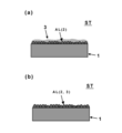
- FIG. 1 is a cross-sectional view schematically showing the structure of the surface-treated steel sheet ST according to this embodiment, and more specifically, the above-described base material 1 and the surface treatment layer are schematically shown. .
- the surface treatment layer includes the granular Ni plating layer 2 and the Sn plating layer 3.
- the granular Ni plating layer 2 has a granular appearance on the substrate 1.
- “granular” means a state having the following characteristic values at the same time.
- the particle density of the granular Ni plating layer 2 in this embodiment is 500 / ⁇ m 2 to 1000 / ⁇ m 2 .
- the particle density is less than 500 particles / ⁇ m 2 , the nickel particles are too fine, the plating surface shape becomes too flat, and sufficient adhesion cannot be obtained.
- the particle density exceeds 1000 particles / ⁇ m 2 , the plating surface shape becomes too smooth and sufficient adhesion cannot be obtained.
- this granular Ni plating layer 2 and Sn plating layer 3 can be combined to produce an effect of excellent adhesion and corrosion resistance, but it is desirable to further perform heat treatment.
- an effect of further excellent adhesion can be produced. That is, a Ni—Sn layer or a Ni—Sn—Fe alloy layer is formed by this heat treatment, and these can produce an anchor effect at the side wall of the can, thereby obtaining sufficient adhesion.
- adhesion due to the anchor effect can be obtained even when the Ni plating layer is made of at least one of a Ni—Sn alloy, a Ni—Sn—Fe alloy, and a Ni—Fe alloy. (Details will be described later).
- the “particle density” is a range of 1 ⁇ 1 ⁇ m (that is, 1 ⁇ m 2 ) when the surface of the surface treatment film 2 is observed with a scanning electron microscope (SEM) and the average particle diameter of the particles is approximately 0.5 ⁇ m or less. Is obtained by measuring the number of nickel particles per unit area by counting the number of particles present in the range. In this case, 1 particle was completely included in the 1 ⁇ 1 ⁇ m frame, and 0.5 particles were counted for only a part of the particles contained in the frame. And this operation is performed about five places on the surface of a nickel plating layer, and particle density can be calculated
- the second characteristic value examples include a value of particle diameter (average particle diameter). That is, the average particle diameter of the granular Ni plating layer 2 in this embodiment is 0.01 ⁇ m to 0.05 ⁇ m. If this average particle diameter is less than 0.01 ⁇ m, the nickel plating becomes too fine and smooth, and sufficient adhesion cannot be obtained. On the other hand, if it exceeds 0.05 ⁇ m, the plating surface shape becomes too smooth, and sufficient adhesion cannot be obtained.
- the average particle diameter is calculated by calculating the average occupied area per particle from the particle density per unit area of 1 ⁇ 1 ⁇ m obtained by observing the surface of the surface treatment film 2 with a scanning electron microscope (SEM). The diameter of a circle corresponding to the average occupied area can be calculated and obtained.
- the Sn plating layer 3 formed on the granular Ni plating layer 2 will be described.
- the Sn plating layer 3 is formed on the granular Ni plating layer 2 so as to cover the granular Ni plating layer 2.
- the surface of the Sn plating layer 3 is not smooth following the granular Ni plating layer 2. It is in a state where a rough undulation is formed.
- the above-described granular Ni plating layer 2 is formed on the base material 1 by plating (step 1).
- the plating process is performed so that the Ni plating amount is 0.01 g / m 2 to 1.0 g / m 2 .
- the Ni plating amount is less than 0.01 g / m 2 , the deposited Ni plating amount is not sufficient, and sufficient adhesion cannot be ensured.
- the Ni plating amount exceeds 1.0 g / m 2 , the adhesion due to the expression of the anchor effect is sufficient, but it is not preferable because the cost increases.
- the Sn plating layer 3 is formed on the Ni plating layer 2 described above (step 2).
- the plating process is performed so that the Sn plating amount is 0.4 g / m 2 to 2.0 g / m 2 .
- the Sn plating amount is less than 0.4 g / m 2 , a sufficient Ni—Sn alloy layer or Ni—Sn—Fe alloy layer is not formed during heat treatment, and sufficient adhesion cannot be obtained, and the corrosion resistance is not improved.
- the Sn plating amount exceeds 2.0 g / m 2 , the surface of the film becomes flat, so the anchor effect is small and sufficient adhesion cannot be obtained.
- the Sn plating amount is more preferably 0.4 g / m 2 to 0.7 g / m 2 .
- step 3 a reflow process (melt heat treatment) is performed on the substrate 1 on which the Ni plating layer 2 and the Sn plating layer 3 are formed (step 3).
- a reflow process (melt heat treatment) is performed on the substrate 1 on which the Ni plating layer 2 and the Sn plating layer 3 are formed (step 3).
- a reflow treatment as shown in FIG. 3, near the interface between the Ni plating layer 2 and the Sn plating layer 3, a Ni—Sn alloy layer, a Ni—Fe alloy layer or a Ni—Sn—Fe alloy layer (Referred to as an alloy layer AL), whereby the surface treatment layer of this embodiment is formed on the substrate 1.
- step 3 reflow processing
- step 3 reflow processing
- the alloy layer AL is uniformly formed on the Ni plating layer 2 of the substrate 1, but is not particularly limited to this aspect.
- the alloy layer AL may be partially formed on the Ni plating layer 2 or may be formed so that at least a part of the alloy layer AL is in contact with the substrate 1.
- the heat treatment at the time of the reflow treatment is not particularly limited as long as the heating temperature or the heating time is a condition that the alloying of Ni and Sn proceeds and the above-described alloy layer is formed. It is preferable that the heating temperature is 180 to 240 ° C. and the heating time is 0.1 to 8 seconds. Further, even when the reflow treatment is not performed, it is sufficient to perform at 220 ° C.
- step 3 (melting heat treatment) after forming the Sn plating layer 3 is not essential, and the above-described alloy layer AL may be formed by heat treatment when the organic resin layer is laminated. Therefore, when manufacturing the organic resin-coated steel sheet of the present embodiment described later, a Ni—Sn alloy layer, a Ni—Fe alloy layer, or a Ni—Sn—Fe alloy layer is present. Therefore, the presence of these alloy layers is not always essential. However, from the viewpoint of suppressing the generation of smudge (tin powder) in the plating line and the laminating process, it can be said that it is preferable to perform Step 3 (melting heat treatment).
- the Ni plating layer may be formed of a Ni—Sn alloy, a Ni—Sn—Fe alloy, or a Ni—Fe alloy (the entire Ni plating layer may be alloyed).
- the Ni plating layer 2 becomes the alloy layer AL, and the Sn plating layer 3 is coated on the alloy layer AL.
- alloying may occur until the Sn plating layer 3 does not remain on the alloy layer AL.
- a coating layer 4 or an organic resin layer 5 described later is coated. That is, in FIG.
- the Sn plating layer 3 is alloyed and changed to the alloy layer AL, but such a form is also included in the surface treatment layer of the present invention.
- the surface-treated steel sheet ST of the present embodiment is manufactured.
- the coating layer 4 as a film of at least one oxide of Ti and Al (for example, ZrO 2 , TiO 2 , Al 2 O 3, etc.) may be formed. That is, in the present embodiment, the step of forming the coating layer 4 is not essential, but it is more preferable if the coating layer 4 is on the surface treatment layer.
- step 4 formation of the coating layer 4
- step 4 formation of coating layer 4
- step 4 formation of coating layer 4
- step 4 formation of coating layer 4
- step 4 formation of coating layer 4
- step 4 formation of coating layer 4
- step 4 omitted
- step 2 to step 5 it is possible to move from step 2 to step 5 or from step 3 to step 5.
- the coating layer 4 of this embodiment may contain not only the above oxide but also a hydroxide. Therefore, the “oxide” in the present embodiment is used as a concept that may contain a hydroxide at least in part.
- the formation of the coating layer 4 is not limited to the above.
- a film in a form using a passivating action such as molybdic acid (including a form to which a predetermined ratio of phosphoric acid is added) or tungstic acid
- Reactive coatings based on fluorides, phosphates, nitrates and sulfates of transition metals such as Ti, Zr, V, Mn, Ni and Co, and polypinylphenol derivatives and polyacrylic acid Coated coating type coatings (3) reactive type coatings based on chlorides and nitrates of rare elements such as Y, La, and Ce, or oxyacid salts such as molybdic acid and tungstic acid
- Films based on polyphenolic carboxylic acids such as tannic acid and chelating agents such as thiourea containing sulfur and nitrogen.
- Various forms of coating may be used.
- the coating layer 4 may contain an oxide of phosphorus in addition to the above oxide.
- a phosphate compound layer made of Fe or Sn may be formed, or may be formed in the form of a phosphate compound such as Zr phosphate or Al phosphate.
- phosphoric acid By containing phosphoric acid, adhesion with the organic resin layer can be improved and plating defects such as pinholes can be reduced.
- the coating amount of the coating layer 4, Zr oxide, Al oxide, both 1 ⁇ 30mg / m 2 of Ti oxides, oxides of phosphorus is preferably 0.1 ⁇ 5mg / m 2.
- the oxide of phosphorus when a coating layer mainly composed of oxides of P (phosphorus) and Al (aluminum) is formed, the Al coating amount is preferably 1 to 15 mg / m 2 .
- the preferable coating amount of P with respect to Al is 0.5 to 3 mg / m 2 .
- the organic resin layer 5 may be formed on the surface-treated steel plate ST described above. More specifically, after the above-described surface-treated steel plate ST is manufactured, or when the above-described coating layer 4 is formed, after the formation of the coating layer 4, an organic resin layer 5 is formed thereon to form an organic layer. A resin-coated steel sheet RT is manufactured. Although the description of the alloy layer AL is omitted in FIG. 6, the alloy layer AL described above may be formed in the vicinity of the interface between the Ni plating layer 2 and the Sn plating layer 3 as in the case of FIG. As in the case of FIG.
- the Ni plating layer 2 and the Sn plating layer 3 may be completely alloyed to form the alloy layer AL.
- Various known paints can be applied to the organic resin layer 5, and examples thereof include polyester resins, epoxy phenol resins, and polyvinyl chloride resins.
- polyester resins are preferred because they are easy to paint and bake, have excellent workability, adhesion to metals, and retort resistance, and do not generate toxic or corrosive gases during incineration.
- polyester resins include ethylene terephthalate, butylene terephthalate, 1,4-cyclohexanedimethyl terephthalate, ethylene isophthalate, butylene isophthalate, ethylene adipate, butylene adipate, ethylene naphthalate, and butylene naphthalate.
- polyester resins containing the above esters include polyester resins containing the above esters.
- the organic resin layer 5 of the present embodiment may be a multilayer film composed of a plurality of layers, and may preferably be composed of two or three layers.
- FIG. 7 shows a seamless can using the surface-treated steel sheet ST and the organic resin-coated steel sheet RT of the present embodiment.
- FIG. 7 shows an example in which the surface treatment layer, the coating layer 4 and the organic resin layer 5 described above are coated on the inner surface side of the seamless can.
- the film surface treatment layer, coating layer 4, organic resin layer 5, etc.
- the film of this embodiment may be formed on both the inner and outer surfaces of the seamless can, and other known films may be formed on the other surface side.
- Example 1 A cold rolled steel sheet of low carbon aluminum killed steel having a thickness of 0.225 mm was used as a base material.
- this base material was electrolytically degreased in an aqueous alkaline solution and washed with water, and further washed with sulfuric acid and washed with water, and then formed into a concavo-convex shape with a nickel plating film amount of 0.02 g / m 2 in a nickel plating bath. A granular Ni plating layer was formed.
- the Sn plating layer was formed by setting the amount of Sn plating to 0.7 g / m 2 in a tin plating bath.
- the particle density in the Ni plating layer was 800 particles / ⁇ m 2 and the average particle size was 0.03 ⁇ m.
- the surface-treated steel sheet ST obtained under the above conditions is subjected to reflow treatment (heating treatment), and the above alloy layers (Ni—Sn alloy layer, Ni—Fe alloy layer and Ni—Sn—Fe alloy layer) are formed. Formed.
- the types of alloy layers to be formed need not be all of the Ni—Sn alloy layer, the Ni—Fe alloy layer, and the Ni—Sn—Fe alloy layer, and an aspect in which at least one of them is formed. But you can.
- the melt heat treatment was performed for 5.6 seconds at a temperature of 240 ° C. higher than the melting point of Sn.
- the heating temperature can be appropriately selected as long as it is within the melting point of tin or higher, and the heating time can be appropriately selected as long as it is within the range of 0.1 second to 8 seconds. .
- the heating temperature or heating time is not particularly limited as long as the alloying of Ni and Sn proceeds and the above-described alloy layer is formed.
- the specific plating bath conditions were as follows. ⁇ Nickel plating bath and plating conditions> Nickel sulfate 40g / L Ammonium sulfate 20g / L Citric acid 15g / L pH 4.0 Bath temperature 45 ° C Current density 50A / dm 2 The amount of nickel sulfate may be adjusted as appropriate as long as it is 40 to 60 g / L. The amount of ammonium sulfate may be adjusted as appropriate as long as it is 20 to 100 g / L.
- ⁇ Tin plating bath and plating conditions Stannous sulfate 80g / L Phenolsulfonic acid 60g / L Additive A (Ethoxylated- ⁇ -naphthol) 3g / L Additive B (Ethoxynaphtholsulfonic acid) 3g / L pH 1 or less Bath temperature 40 ° C Current density 10A / dm 2 The amount of stannous sulfate may be adjusted as appropriate as long as it is 10 to 200 g / L. Further, the amount of phenolsulfonic acid sulfuric acid may be appropriately adjusted as long as it is 5 to 100 g / L.
- a coating layer (coating amount 5.0 mg / m 2 ) mainly composed of an oxide of Zr (zirconium) was formed on the surface-treated steel sheet. Then, the surface-treated steel sheet on which the coating layer was formed was heat-treated at a temperature of 220 ° C. for 30 seconds, and a polyethylene terephthalate unstretched film (thickness 20 ⁇ m) in which 12 mol% of isophthalic acid was modified on both surfaces was heat-laminated.
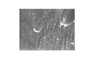
- FIG. 8A shows an SEM image relating to the surface morphology after Ni plating in Example 1
- FIG. 8B shows an SEM image relating to the surface morphology after undergoing Sn plating and reflow treatment.
- This SEM image was obtained by observing the surface under the conditions of an acceleration voltage of 5 kV and a current of 12 ⁇ A using a scanning electron microscope (manufactured by Hitachi High-Technologies Corporation, SU8020), and performing imaging.
- Example 2 The same procedure as in Example 1 was performed, except that the temperature in the reflow treatment was 210 ° C. and the coating amount of the coating layer mainly composed of Zr oxide was 9.3 mg / m 2 .
- Example 3 In the formation of the Ni plating layer, the coating amount of Ni plating is 0.1 g / m 2 , the particle density is 504 particles / ⁇ m 2 , the average particle size is 0.05 ⁇ m, and the main component is Zr oxide. The same operation as in Example 1 was performed except that the coating amount of the layer was 6.4 mg / m 2 .
- the SEM image regarding the surface form after Ni plating in Example 3 is shown in FIG.
- Example 4 In the formation of the Ni plating layer, the coating amount of Ni plating is 0.1 g / m 2 , the particle density is 504 particles / ⁇ m 2 , the average particle size is 0.05 ⁇ m, the temperature in reflow treatment is 210 ° C., and Zr This was carried out in the same manner as in Example 1 except that the coating amount of the coating layer containing as a main component the oxide was 7.3 mg / m 2 .
- Example 5 In forming the Ni plating layer, the coating amount of Ni plating was 0.5 g / m 2 , the particle density was 610 particles / ⁇ m 2 , and the average particle size was 0.05 ⁇ m. Further, in the formation of the Sn plating layer, the coating amount of Sn plating was 1.4 g / m 2, and the coating amount of the coating layer mainly composed of Zr oxide was 8.0 mg / m 2 . Except for the above, the same procedure as in Example 1 was performed.
- the coating amount of Ni plating was 0.5 g / m 2 , the particle density was 610 particles / ⁇ m 2 , and the average particle size was 0.05 ⁇ m. Further, in the formation of the Sn plating layer, the coating amount of the Sn plating is 1.5 g / m 2 and the reflow treatment is not performed, and the coating amount of the coating layer mainly composed of Zr oxide is 5.1 mg / m 2. It was. Except for the above, the same procedure as in Example 1 was performed.
- Example 7 In forming the Ni plating layer, the coating amount of Ni plating was 0.5 g / m 2 , the particle density was 610 particles / ⁇ m 2 , and the average particle size was 0.05 ⁇ m. Further, in the formation of the Sn plating layer, the coating amount of the Sn plating is 1.5 g / m 2 , the temperature in the reflow treatment is 210 ° C., and the coating amount of the coating layer mainly composed of Zr oxide is 5. It was 9 mg / m 2 . Except for the above, the same procedure as in Example 1 was performed.
- the coating amount of Ni plating was 0.5 g / m 2
- the particle density was 610 particles / ⁇ m 2
- the average particle size was 0.05 ⁇ m.
- the film amount of Sn plating was 0.7 g / m ⁇ 2 >, and the reflow process was not performed.
- the surface-treated steel sheet ST manufactured through the above steps was subjected to cathodic electrolysis in a pH 3.0 treatment bath containing aluminum nitrate as a main component, and then washed with water and dried.
- Example 2 instead of the coating layer mainly composed of the oxide of Zr in Example 1, a coating layer mainly composed of an oxide of Al (aluminum) was formed on the surface-treated steel sheet ST, and the coating amount was It was set to 7.7 mg / m 2 . Except for the above, the same procedure as in Example 1 was performed.
- Example 9 In forming the Ni plating layer, the coating amount of Ni plating was 0.5 g / m 2 , the particle density was 610 particles / ⁇ m 2 , and the average particle size was 0.05 ⁇ m. Further, in the formation of the Sn plating layer, the coating amount of the Sn plating layer is 0.7 g / m 2 , the temperature in the reflow process is 210 ° C., and the coating amount of the coating layer mainly composed of an oxide of Al (aluminum). Was 9.3 mg / m 2 . Except for the above, the same procedure as in Example 1 was performed.
- the coating amount of Ni plating was 0.5 g / m 2 , the particle density was 610 particles / ⁇ m 2 , and the average particle size was 0.05 ⁇ m. Further, in the formation of the Sn plating layer, the coating amount of Sn plating is set to 0.4 g / m 2 , the reflow treatment is not performed, and the coating amount of the coating layer mainly composed of an oxide of Al (aluminum) is set to 9. It was 9 mg / m 2 . Except for the above, the same procedure as in Example 1 was performed.
- the coating amount of Ni plating was 0.5 g / m 2 , the particle density was 610 particles / ⁇ m 2 , and the average particle size was 0.05 ⁇ m. Further, in the formation of the Sn plating layer, the coating amount of the Sn plating layer is set to 0.4 g / m 2 , the temperature in the reflow treatment is set to 210 ° C., and the coating amount of the coating layer mainly composed of an oxide of Al (aluminum). Was 8.9 mg / m 2 . Except for the above, the same procedure as in Example 1 was performed.
- the coating amount of Ni plating was 0.5 g / m 2
- the particle density was 610 particles / ⁇ m 2
- the average particle size was 0.05 ⁇ m.
- the coating amount of the Sn plating layer is 0.4 g / m 2
- the temperature in the reflow process is 240 ° C.
- the coating amount of the coating layer mainly composed of an oxide of Al (aluminum). was 10.6 mg / m 2 . Except for the above, the same procedure as in Example 1 was performed.
- the coating amount of Ni plating was 0.5 g / m 2
- the particle density was 610 particles / ⁇ m 2
- the average particle size was 0.05 ⁇ m.
- the coating amount of the Sn plating layer is set to 0.7 g / m 2
- the temperature in the reflow process is set to 240 ° C.
- the coating amount of the coating layer mainly composed of an oxide of Al (aluminum). was 11.3 mg / m 2 . Except for the above, the same procedure as in Example 1 was performed.
- Example 14> In forming the Ni plating layer, the coating amount of Ni plating was 0.1 g / m 2 , the particle density was 504 particles / ⁇ m 2 , and the average particle size was 0.05 ⁇ m. Moreover, in Sn plating layer formation, the film quantity of Sn plating was 0.7 g / m ⁇ 2 >, and the temperature in a reflow process was 240 degreeC. In this example, no coating layer was formed. Except for the above, the same procedure as in Example 1 was performed.
- Example 15 In forming the Ni plating layer, the coating amount of Ni plating was 0.1 g / m 2 , the particle density was 504 particles / ⁇ m 2 , the average particle size was 0.05 ⁇ m, and the reflow temperature was 240 ° C.
- cathodic electrolysis was performed in a pH 3.0 treatment bath containing aluminum nitrate as a main component, followed by washing with water and drying.
- a coating layer mainly composed of an oxide of Al (aluminum) was formed, and the coating amount was 5.8 mg / m 2 . did. Except for the above, the same procedure as in Example 1 was performed.
- Example 16> As a post-treatment, anodic electrolysis was performed in a treatment solution having a pH of 2.4 containing phosphoric acid and sodium dihydrogen phosphate as main components, followed by washing with water. Furthermore, by performing cathodic electrolysis in a pH 3.0 treatment bath containing aluminum nitrate as a main component, followed by washing with water and drying, P (phosphorus) and Al (aluminum) on the surface-treated steel sheet ST. A coating layer mainly composed of oxide was formed. Coating amount of P of the coating layer coating weight of 2 mg / m 2, and Al was 5.6 mg / m 2. Except for the above, the same procedure as in Example 15 was performed.
- Example 17 In forming the Sn plating layer, the coating amount of Sn plating was 1.3 g / m 2 .
- the coating amount of the coating layer mainly composed of an oxide of Al was 6 mg / m 2 . Except for the above, the same procedure as in Example 15 was performed.
- Example 18 In the formation of the Sn plating layer, the coating amount of Sn plating was 1.4 g / m 2 . Coating amount of the coating layer mainly composed of oxides of P and Al, respectively was 2 mg / m 2 and 6.2 mg / m 2. Except for the above, the same procedure as in Example 16 was performed.
- the coating amount of Ni plating was 0.5 g / m 2 , the particle density was 610 particles / ⁇ m 2 , and the average particle size was 0.05 ⁇ m. Further, in forming the Sn plating layer, the coating amount of Sn plating is set to 2.8 g / m 2 , the reflow treatment is not performed, and the coating amount of the coating layer mainly composed of an oxide of Al (aluminum) is set to 3. The amount was 8 mg / m 2 . Except for the above, the same procedure as in Example 1 was performed.
- the coating amount of Ni plating was 0.5 g / m 2 , the particle density was 610 particles / ⁇ m 2 , and the average particle size was 0.05 ⁇ m. Moreover, in Sn plating layer formation, the film quantity of Sn plating was 2.8 g / m ⁇ 2 >, and the temperature in a reflow process was 210 degreeC. Further, the coating amount of the coating layer mainly composed of an oxide of Al (aluminum) was set to 3.8 mg / m 2 . Except for the above, the same procedure as in Example 1 was performed.
- the coating amount of Ni plating was 0.5 g / m 2 , the particle density was 610 particles / ⁇ m 2 , and the average particle size was 0.05 ⁇ m.
- the film amount of Sn plating was 2.8 g / m ⁇ 2 >, and the temperature in a reflow process was 240 degreeC.
- the coating amount of the coating layer mainly composed of an oxide of Al (aluminum) was set to 3.8 mg / m 2 . Except for the above, the same procedure as in Example 1 was performed.
- Example 4 A Watt bath was used as the Ni plating bath.
- the coating amount of the Ni plating was set to 0.1 g / m 2 while preventing the form of the coating from becoming granular.
- the film quantity of Sn plating was 0.7 g / m ⁇ 2 >, and the temperature in a reflow process was 240 degreeC.
- the coating amount of the coating layer mainly composed of an oxide of Zr (zirconium) was 6.0 mg / m 2 . Except for the above, the same procedure as in Example 1 was performed.
- the SEM image regarding the surface form after Ni plating in this comparative example 4 is shown in FIG.
- the specific conditions of the watt bath in the comparative example 4 were as follows. ⁇ Nickel plating bath and plating conditions in Watt bath> Nickel sulfate 240g / L Nickel chloride 45g / L Boric acid 30g / L Additives (saccharin, etc.) 2g / L pH 4.0 Bath temperature 45 ° C Current density 5A / dm 2
- ⁇ Comparative Example 5> The same watt bath as in Comparative Example 4 was used as the Ni plating bath.
- the coating amount of the Ni plating was set to 0.5 g / m 2 while preventing the form of the coating from becoming granular.
- the film quantity of Sn plating was 0.7 g / m ⁇ 2 >, and the temperature in a reflow process was 210 degreeC.
- the coating amount of the coating layer mainly composed of an oxide of Al (aluminum) was set to 4.3 mg / m 2 . Except for the above, the same procedure as in Example 1 was performed.
- ⁇ Comparative Example 6> The same watt bath as in Comparative Example 4 was used as the Ni plating bath.
- the coating amount of the Ni plating was set to 0.5 g / m 2 while preventing the form of the coating from becoming granular.
- the film quantity of Sn plating was 0.7 g / m ⁇ 2 >, and the temperature in a reflow process was 240 degreeC.
- the coating amount of the coating layer mainly composed of an oxide of Al (aluminum) was set to 6.4 mg / m 2 . Except for the above, the same procedure as in Example 1 was performed.
- Example 7 The same plating bath as in Example 1 was used as the Ni plating bath.
- the coating amount of Ni plating was 0.1 g / m 2
- the particle density was 504 particles / ⁇ m 2
- the average particle size was 0.1 ⁇ m.
- the Sn plating layer and the coating layer were not formed.
- it carried out similarly to Example 1 except the above.
- This comparative example corresponds to Example 1 in Patent Document 2 described above.
- ⁇ Reference example> As an example of the prior art, a cover plate was produced. At this time, the Sn plating amount was 2.8 g / ⁇ m 2 and the Cr plating amount was 4.0 mg / m 2 .
- the coating amount was measured, the surface morphology was observed, and various evaluations were performed by the following methods.
- ⁇ Measurement of coating amount of Ni and Sn> The coating amounts of Ni and Sn on the surface-treated steel sheet were measured with a fluorescent X-ray analyzer (manufactured by Rigaku Corporation, ZSX100e).
- the obtained organic resin-coated steel sheet was evaluated for corrosion resistance (including film adhesion) in the model solution.
- As the model solution an aqueous solution in which NaCl and citric acid were dissolved at 1.5% by weight was used. More specifically, a wax for lubrication was applied on both surfaces of an organic resin-coated steel sheet, punched out into a blank having a diameter of 150 mm, and then drawn into a cylindrical cup with a drawing ratio of 1.67. And the can bottom and can side wall part of the cup were cut into 4 cm ⁇ 4 cm, and after sealing the end face, a scratch having a depth reaching this steel plate was applied in a cross-cut shape.
- this steel plate was immersed in the model solution mentioned above, and the retort process was performed for 30 minutes at 125 degreeC, and also it was made to age only for 5 days in 37 degreeC environment. Then, this steel plate was taken out from the model solution, and the degree of corrosion of the test piece was visually observed and evaluated according to the following criteria. In addition, corrosion resistance and adhesiveness evaluation (model liquid) were performed about all the said Examples and comparative examples. Moreover, about some samples, the cup was heat-treated for 3 minutes at 215 ° C., and after heat-treating to relieve stress in the unstretched film, it was cut out and used for corrosion resistance evaluation.
- Table 1 shows the material specifications and evaluation results for each of the examples and comparative examples described above.
- the can bottom and the can wall all have corrosion resistance and adhesion exceeding the tinplate having chromate treatment.
- the comparative example it was confirmed that at least one of the can bottom and the can wall had a higher degree of corrosion than the tinplate and could not be put into practical use.
- the surface-treated steel sheet, the organic resin-coated steel sheet and the container using the same according to the present invention have high levels of corrosion resistance and adhesion at the same time, and can be applied to a wide range of industries.
Landscapes
- Chemical & Material Sciences (AREA)
- Engineering & Computer Science (AREA)
- Chemical Kinetics & Catalysis (AREA)
- Materials Engineering (AREA)
- Metallurgy (AREA)
- Organic Chemistry (AREA)
- Electrochemistry (AREA)
- Crystallography & Structural Chemistry (AREA)
- Mechanical Engineering (AREA)
- Inorganic Chemistry (AREA)
- Electroplating Methods And Accessories (AREA)
Abstract
La problème à résoudre par la présente invention est de fournir une tôle d'acier traitée en surface et une tôle d'acier revêtue de résine organique, l'adhérence d'une résine de revêtement étant conservée sans augmenter de manière excessive la quantité de placage de Ni ; un procédé de production d'une telle tôle d'acier ; et un récipient utilisant ladite tôle d'acier revêtue de résine organique. La solution de l'invention consiste en une tôle d'acier traitée en surface qui comprend : un substrat ; une couche de placage de Ni particulaire formée sur le substrat ; et une couche de placage de Sn formée sur la couche de placage de Ni. La densité de particules de Ni dans la couche de placage de Ni est de 500 à 1000/µ2 et le diamètre moyen des particules de Ni va de 0,01 à 0,05 µm. La quantité de placage dans la couche de placage de Ni est de 0,01 à 1,0 g/m2 et la quantité de placage dans la couche de placage de Sn est de 0,4 à 2,0 g/m2.
Applications Claiming Priority (4)
| Application Number | Priority Date | Filing Date | Title |
|---|---|---|---|
| JP2015-148855 | 2015-07-28 | ||
| JP2015148855 | 2015-07-28 | ||
| JP2015-223912 | 2015-11-16 | ||
| JP2015223912A JP6635761B2 (ja) | 2015-07-28 | 2015-11-16 | 表面処理鋼板およびその製造方法、並びにこの表面処理鋼板を用いた容器 |
Publications (1)
| Publication Number | Publication Date |
|---|---|
| WO2017018286A1 true WO2017018286A1 (fr) | 2017-02-02 |
Family
ID=57885571
Family Applications (1)
| Application Number | Title | Priority Date | Filing Date |
|---|---|---|---|
| PCT/JP2016/071222 Ceased WO2017018286A1 (fr) | 2015-07-28 | 2016-07-20 | Tôle d'acier traitée en surface, son procédé de production et récipient l'utilisant |
Country Status (1)
| Country | Link |
|---|---|
| WO (1) | WO2017018286A1 (fr) |
Cited By (2)
| Publication number | Priority date | Publication date | Assignee | Title |
|---|---|---|---|---|
| CN108728879A (zh) * | 2017-04-19 | 2018-11-02 | 优尔工业材料(廊坊)有限公司 | 铁基金属与塑料的复合体及其制备方法 |
| WO2023243717A1 (fr) * | 2022-06-17 | 2023-12-21 | 日本製鉄株式会社 | Tôle d'acier étamée et boîte |
Citations (4)
| Publication number | Priority date | Publication date | Assignee | Title |
|---|---|---|---|---|
| JPH06293996A (ja) * | 1993-04-06 | 1994-10-21 | Nippon Steel Corp | 高速シーム溶接性、耐食性、耐熱性および塗料密着性に優れた溶接缶用素材 |
| JP2008274417A (ja) * | 2007-03-30 | 2008-11-13 | Nikko Kinzoku Kk | 積層銅箔及びその製造方法 |
| WO2012042973A1 (fr) * | 2010-09-29 | 2012-04-05 | 新日本製鐵株式会社 | Canette refermable en trois parties pour liquide acide |
| JP2013007100A (ja) * | 2011-06-24 | 2013-01-10 | Nippon Steel & Sumitomo Metal Corp | 酸性飲料用3ピースリシール缶 |
-
2016
- 2016-07-20 WO PCT/JP2016/071222 patent/WO2017018286A1/fr not_active Ceased
Patent Citations (4)
| Publication number | Priority date | Publication date | Assignee | Title |
|---|---|---|---|---|
| JPH06293996A (ja) * | 1993-04-06 | 1994-10-21 | Nippon Steel Corp | 高速シーム溶接性、耐食性、耐熱性および塗料密着性に優れた溶接缶用素材 |
| JP2008274417A (ja) * | 2007-03-30 | 2008-11-13 | Nikko Kinzoku Kk | 積層銅箔及びその製造方法 |
| WO2012042973A1 (fr) * | 2010-09-29 | 2012-04-05 | 新日本製鐵株式会社 | Canette refermable en trois parties pour liquide acide |
| JP2013007100A (ja) * | 2011-06-24 | 2013-01-10 | Nippon Steel & Sumitomo Metal Corp | 酸性飲料用3ピースリシール缶 |
Cited By (4)
| Publication number | Priority date | Publication date | Assignee | Title |
|---|---|---|---|---|
| CN108728879A (zh) * | 2017-04-19 | 2018-11-02 | 优尔工业材料(廊坊)有限公司 | 铁基金属与塑料的复合体及其制备方法 |
| CN108728879B (zh) * | 2017-04-19 | 2020-02-28 | 优尔工业材料(廊坊)有限公司 | 铁基金属与塑料的复合体及其制备方法 |
| WO2023243717A1 (fr) * | 2022-06-17 | 2023-12-21 | 日本製鉄株式会社 | Tôle d'acier étamée et boîte |
| JPWO2023243717A1 (fr) * | 2022-06-17 | 2023-12-21 |
Similar Documents
| Publication | Publication Date | Title |
|---|---|---|
| JP4920800B2 (ja) | 容器用鋼板の製造方法 | |
| CN101010452B (zh) | 表面处理金属材料及其表面处理方法、和包覆树脂的金属材料、罐及罐盖 | |
| JP6787500B2 (ja) | 缶用鋼板およびその製造方法 | |
| EP2551378B1 (fr) | Tôle d'acier pour récipient qui présente une excellente résistance à la corrosion | |
| WO2018225739A1 (fr) | Tôle d'acier destinée à des canettes et procédé de production s'y rapportant | |
| CN102027158A (zh) | 镀锡钢板及其制造方法以及化学转化处理液 | |
| JP6119930B2 (ja) | 容器用鋼板及び容器用鋼板の製造方法 | |
| JP4615807B2 (ja) | 表面処理鋼板の製造方法、表面処理鋼板、および樹脂被覆表面処理鋼板 | |
| JP5093409B2 (ja) | 耐食性に優れた飲料缶用鋼板 | |
| WO2017018286A1 (fr) | Tôle d'acier traitée en surface, son procédé de production et récipient l'utilisant | |
| KR20160113739A (ko) | 용기용 강판 및 그 제조 방법 | |
| JP6635761B2 (ja) | 表面処理鋼板およびその製造方法、並びにこの表面処理鋼板を用いた容器 | |
| JP6119931B2 (ja) | 容器用鋼板及び容器用鋼板の製造方法 | |
| CN102084032B (zh) | 镀锡钢板及其制造方法 | |
| WO2017018289A1 (fr) | Tôle d'acier traitée en surface, son procédé de production et contenant utilisant ladite tôle d'acier traitée en surface | |
| JP6590651B2 (ja) | 表面処理鋼板およびその製造方法、並びにこの表面処理鋼板を用いた容器 | |
| JP6650251B2 (ja) | 表面処理鋼板およびその製造方法、並びにこの表面処理鋼板を用いた容器 | |
| WO2016002886A1 (fr) | Procédé de production de substrat traité en surface | |
| WO2017014117A1 (fr) | Tôle d'acier traitée en surface, son procédé de fabrication et contenant dans lequel ladite tôle d'acier traitée en surface est utilisée | |
| JP2016084527A (ja) | 容器用鋼板およびその製造方法 |
Legal Events
| Date | Code | Title | Description |
|---|---|---|---|
| 121 | Ep: the epo has been informed by wipo that ep was designated in this application |
Ref document number: 16830391 Country of ref document: EP Kind code of ref document: A1 |
|
| NENP | Non-entry into the national phase |
Ref country code: DE |
|
| 122 | Ep: pct application non-entry in european phase |
Ref document number: 16830391 Country of ref document: EP Kind code of ref document: A1 |