WO2017018335A1 - Dispositif d'entraînement par moteur - Google Patents
Dispositif d'entraînement par moteur Download PDFInfo
- Publication number
- WO2017018335A1 WO2017018335A1 PCT/JP2016/071507 JP2016071507W WO2017018335A1 WO 2017018335 A1 WO2017018335 A1 WO 2017018335A1 JP 2016071507 W JP2016071507 W JP 2016071507W WO 2017018335 A1 WO2017018335 A1 WO 2017018335A1
- Authority
- WO
- WIPO (PCT)
- Prior art keywords
- vehicle speed
- torque
- maximum
- vehicle
- command value
- Prior art date
- Legal status (The legal status is an assumption and is not a legal conclusion. Google has not performed a legal analysis and makes no representation as to the accuracy of the status listed.)
- Ceased
Links
Images




Classifications
-
- B—PERFORMING OPERATIONS; TRANSPORTING
- B60—VEHICLES IN GENERAL
- B60L—PROPULSION OF ELECTRICALLY-PROPELLED VEHICLES; SUPPLYING ELECTRIC POWER FOR AUXILIARY EQUIPMENT OF ELECTRICALLY-PROPELLED VEHICLES; ELECTRODYNAMIC BRAKE SYSTEMS FOR VEHICLES IN GENERAL; MAGNETIC SUSPENSION OR LEVITATION FOR VEHICLES; MONITORING OPERATING VARIABLES OF ELECTRICALLY-PROPELLED VEHICLES; ELECTRIC SAFETY DEVICES FOR ELECTRICALLY-PROPELLED VEHICLES
- B60L15/00—Methods, circuits, or devices for controlling the traction-motor speed of electrically-propelled vehicles
- B60L15/20—Methods, circuits, or devices for controlling the traction-motor speed of electrically-propelled vehicles for control of the vehicle or its driving motor to achieve a desired performance, e.g. speed, torque, programmed variation of speed
-
- H—ELECTRICITY
- H02—GENERATION; CONVERSION OR DISTRIBUTION OF ELECTRIC POWER
- H02P—CONTROL OR REGULATION OF ELECTRIC MOTORS, ELECTRIC GENERATORS OR DYNAMO-ELECTRIC CONVERTERS; CONTROLLING TRANSFORMERS, REACTORS OR CHOKE COILS
- H02P21/00—Arrangements or methods for the control of electric machines by vector control, e.g. by control of field orientation
- H02P21/22—Current control, e.g. using a current control loop
-
- Y—GENERAL TAGGING OF NEW TECHNOLOGICAL DEVELOPMENTS; GENERAL TAGGING OF CROSS-SECTIONAL TECHNOLOGIES SPANNING OVER SEVERAL SECTIONS OF THE IPC; TECHNICAL SUBJECTS COVERED BY FORMER USPC CROSS-REFERENCE ART COLLECTIONS [XRACs] AND DIGESTS
- Y02—TECHNOLOGIES OR APPLICATIONS FOR MITIGATION OR ADAPTATION AGAINST CLIMATE CHANGE
- Y02T—CLIMATE CHANGE MITIGATION TECHNOLOGIES RELATED TO TRANSPORTATION
- Y02T10/00—Road transport of goods or passengers
- Y02T10/60—Other road transportation technologies with climate change mitigation effect
- Y02T10/64—Electric machine technologies in electromobility
-
- Y—GENERAL TAGGING OF NEW TECHNOLOGICAL DEVELOPMENTS; GENERAL TAGGING OF CROSS-SECTIONAL TECHNOLOGIES SPANNING OVER SEVERAL SECTIONS OF THE IPC; TECHNICAL SUBJECTS COVERED BY FORMER USPC CROSS-REFERENCE ART COLLECTIONS [XRACs] AND DIGESTS
- Y02—TECHNOLOGIES OR APPLICATIONS FOR MITIGATION OR ADAPTATION AGAINST CLIMATE CHANGE
- Y02T—CLIMATE CHANGE MITIGATION TECHNOLOGIES RELATED TO TRANSPORTATION
- Y02T10/00—Road transport of goods or passengers
- Y02T10/60—Other road transportation technologies with climate change mitigation effect
- Y02T10/72—Electric energy management in electromobility
Definitions
- the present invention relates to a motor drive device, and relates to a technique capable of reducing a sense of discomfort given to a driver of a vehicle equipped with the motor drive device.
- the accelerator opening is linearly converted into a torque command value, and the electric motor is driven with the torque command value of the magnitude via an inverter.
- the change amount of the motor load factor is reduced in a region where the accelerator opening is small, and is increased in a region where the accelerator opening is medium.
- the inverter often performs control to limit the output of the electric motor. In this control, there is a device that reduces the output torque of the electric motor in accordance with an increase in the vehicle speed.
- the indications “100%”, “90%”,..., “50%” represent the ratio of the amount of depression that reaches the maximum torque corresponding to the vehicle speed with respect to the maximum depression amount of the accelerator pedal. .
- the critical speed of this ratio that is, the boundary speed between the ratio of 100% and the ratio less than 100% is set as the specified vehicle speed.
- An object of the present invention is to provide a motor drive device that can prevent a driver from feeling uncomfortable when a driver of a vehicle equipped with a motor drive device operates an accelerator operation means.
- a motor drive device includes an electric motor 5 that drives wheels 2 and 2 provided in a vehicle, vehicle speed detection means 7 that detects a vehicle speed of the vehicle, and a control that controls the electric motor 5.
- Device 6. receives a signal indicating the amount of operation of the accelerator operation means 12 of the vehicle and outputs a drive command, and outputs the drive command output from the host control unit 8 to the vehicle speed detection means.
- the vehicle speed-corresponding torque control means 10 includes an accelerator sensitivity adjustment unit 10a that adjusts according to the vehicle speed detected by the vehicle 7 and outputs the adjusted torque command value as an adjusted drive command, and is output by the vehicle speed-corresponding torque control means 10. And a torque control unit 11 for controlling the torque of the electric motor 5 in accordance with the adjusted drive command.
- the accelerator sensitivity adjusting unit 10a of the vehicle speed-corresponding torque control unit 10 includes the electric motor in which the adjusted torque command value when the operation amount of the accelerator operation unit 12 is the maximum operation amount depends on the vehicle speed and the vehicle speed. 5 and the maximum torque corresponding to the current vehicle speed detected by the vehicle speed detection means 7, which is uniquely determined from the relationship with the maximum torque corresponding to the vehicle speed 5, and the amount of operation of the accelerator operation means 12 is equal to the adjusted torque.
- the drive command is adjusted so that the command value is proportional.
- being uniquely determined means that since the motor maximum output is determined as the specification of the vehicle, the vehicle speed and the torque with respect to the motor maximum output have a one-to-one relationship.
- the relationship between the vehicle speed and the torque is expressed by, for example, an inversely proportional expression.
- the upper control unit 8 receives a signal indicating the operation amount of the accelerator operation means 12 and outputs a drive command.
- the accelerator sensitivity adjustment unit 10a of the vehicle speed corresponding torque control means 10 adjusts the torque command value given to the torque control unit 11 so as to satisfy all of the following conditions (1) and (2) according to the operation amount.
- the torque command value output from the vehicle speed corresponding torque control means 10 to the torque control unit 11 in response to the signal indicating the maximum operation amount of the accelerator operation means 12 corresponds to the vehicle speed and the vehicle speed of the electric motor 5 depending on the vehicle speed. It corresponds to the maximum torque corresponding to the current vehicle speed, which is uniquely determined from the relationship with the maximum torque.
- the adjusted torque command value is proportional to the operation amount of the accelerator operating means 12.
- the vehicle speed corresponding torque control means 10 can give a torque command value corresponding to the operation amount of the accelerator operation means 12 to the torque control unit 11 during acceleration, for example. Specifically, when the driver tries to operate the accelerator operation means 12 from the operation amount during acceleration to the maximum operation amount, this operation amount is reflected in the torque command value. Therefore, drivability is improved and it is possible to prevent the driver from feeling uncomfortable.
- the motor drive device controls the electric motor 5 that drives the wheels 2 and 2 provided in the vehicle, the vehicle speed detection means 7 that detects the vehicle speed of the vehicle, and the electric motor 5. And a control device 6.
- the control device 6 receives a signal indicating the amount of operation of the accelerator operation means 12 of the vehicle and outputs a drive command, and outputs the drive command output from the host control unit 8 to the vehicle speed detection means.
- the vehicle speed-corresponding torque control means 10 includes an accelerator sensitivity adjustment unit 10a that adjusts according to the vehicle speed detected by the vehicle 7 and outputs the adjusted torque command value as an adjusted drive command, and is output by the vehicle speed-corresponding torque control means 10.
- a torque control unit 11 for controlling the torque of the electric motor in accordance with the adjusted drive command.
- the accelerator sensitivity adjustment unit 10a of the vehicle speed corresponding torque control means 10 obtains the adjusted torque command value (T *) for the vehicle speed detected by the vehicle speed detection means 7 based on the following equation (1).
- T * (Tmax ( ⁇ ) / T0) ⁇ T Equation (1)
- Tmax ( ⁇ ) is the maximum torque corresponding to the vehicle speed at the vehicle speed ⁇ , and is a torque determined from the maximum output of the electric motor
- T0 the maximum motor torque
- T the pre-adjustment torque command value.
- the ratio of the vehicle speed corresponding maximum torque (Tmax ( ⁇ )) at the vehicle speed ⁇ to the motor maximum torque (T0) is multiplied by the pre-adjustment torque command value to obtain the adjusted torque command value. (1) and (2) are satisfied.
- the maximum output (W0) of the electric motor 5 is divided by the vehicle speed ( ⁇ ) detected by the vehicle speed detection means 7 and the vehicle speed ( ⁇ )
- the maximum vehicle speed corresponding torque (Tmax ( ⁇ )) may be obtained.
- the specified vehicle speed is obtained by calculation from the maximum output (W0) of the electric motor 5 and the motor maximum torque (T0), for example.
- the torque command value that follows the vehicle speed is accurately calculated as the adjusted torque command value by using the maximum torque corresponding to the vehicle speed.
- the maximum output (W0) of the electric motor 5 is divided by the specified vehicle speed ( ⁇ 0) to obtain the maximum vehicle speed corresponding torque (Tmax) at the vehicle speed ( ⁇ ). ( ⁇ )) may be obtained.
- the processing load is reduced when the vehicle speed is lower than the specified vehicle speed.
- the accelerator sensitivity adjustment unit 10a may use the current vehicle speed-corresponding maximum torque as the adjusted torque command value. Also in this case, the calculation processing load is reduced.
- the accelerator sensitivity adjustment unit 10a may obtain the adjusted torque command value by using a maximum vehicle speed corresponding torque that is inversely proportional to the vehicle speed.
- the maximum torque corresponding to the vehicle speed may be constant without depending on the vehicle speed depending on the range of the vehicle speed. Further, based on the output characteristics of the inverter and the motor, a maximum vehicle speed corresponding torque with respect to the vehicle speed may be obtained.
- the vehicle speed-corresponding maximum torque with respect to the vehicle speed may be determined by a result of, for example, a test or a simulation.
- FIG. 1 is a block diagram of a conceptual configuration showing, in plan view, an electric vehicle equipped with a motor drive device according to a first embodiment of the present invention. It is a block diagram of the control system of the motor drive device of FIG. It is a block diagram which shows each control part etc. of the motor drive device of FIG. 1 in detail.
- FIG. 1 is a block diagram of a conceptual configuration showing, in plan view, an electric vehicle equipped with a motor drive device according to this embodiment.
- This electric vehicle is a four-wheeled vehicle.
- the left and right rear wheels of the vehicle body 1 are drive wheels 2 and 2, and the left and right front wheels are driven wheels 3 and 3.
- the front wheels 3 and 3 are steering wheels.
- the left and right front wheels 3 and 3 can be steered via a steering mechanism (not shown) and are steered by a steering means 4 such as a steering wheel.
- the left and right drive wheels 2 and 2 are of a one-motor onboard type driven by a single electric motor 5 installed in the vehicle body 1.
- Each wheel 2 and 3 is provided with a brake (not shown).
- the motor drive device 100 includes the electric motor 5, the control device 6, and vehicle speed detection means 7 (FIG. 2) for detecting the vehicle speed.
- a control device 6 that controls the electric motor 5 is mounted on the vehicle body 1.
- the control device 6 includes an ECU 8 that is a host control unit and an inverter device 9.
- the inverter device 9 includes a vehicle speed corresponding torque control means 10 and a torque control unit 11. Between the ECU 8 and the torque control unit 11, a vehicle speed corresponding torque control means 10, which will be described later, is interposed.
- the ECU 8 performs overall control of the entire vehicle, and a drive command output from the ECU 8 is given to the vehicle speed corresponding torque control means 10.
- the ECU 8 includes a computer, a program executed on the computer, various electronic circuits, and the like.
- FIG. 2 is a block diagram of the control system of the motor drive device.
- the ECU 8 has a drive command generation unit 8a and a power running / regeneration control command unit 8b.
- the drive command generation unit 8a is provided with an acceleration command (power running) output from the accelerator operation means 12, a deceleration command (regeneration) output from the brake operation means 13 (see FIG. 1), and steering by the steering means 4 (see FIG. 1). From the turning command output by the steering angle sensor 4a for detecting the angle, an acceleration / deceleration command to be given to the electric motor 5 for traveling is generated as a drive command and output to the vehicle speed corresponding torque control means 10.
- the power running / regenerative control command unit 8 b gives a command flag for designating either power running or regeneration to the vehicle speed corresponding torque control means 10.
- the accelerator operating means 12 has an accelerator pedal 12a and an accelerator sensor 12b that detects the amount of depression (operation amount) of the accelerator pedal 12a.
- the brake operation means 13 includes a brake pedal 13a and a brake sensor 13b that detects the amount of depression of the brake pedal 13a (see FIG. 1).
- FIG. 3 is a block diagram showing in detail each control unit and the like of the motor drive device.
- the torque control unit 11 torque-controls the electric motor 5 in accordance with the drive command output from the drive command generation unit 8 a of the ECU 8 and passed through the vehicle speed corresponding torque control means 10.
- the torque control unit 11 includes a power circuit unit 14 provided for the electric motor 5 and a motor control unit 15 that controls the power circuit unit 14.
- the power circuit unit 14 includes an inverter 14a that converts DC power of the battery 16 into three-phase AC power used for powering or regeneration of the electric motor 5, and a PWM driver 14b that controls the inverter 14a.
- the inverter 14a is composed of a plurality of semiconductor switching elements, and the PWM driver 14b performs pulse width modulation on the input current command and gives an on / off command to each of the semiconductor switching elements.
- the electric motor 5 is a three-phase synchronous motor.
- the electric motor 5 is provided with a rotation angle sensor 17 that detects a rotation angle as an electric angle of the motor rotor.
- the motor control unit 15 is provided with speed calculation means 18.
- the speed calculation means 18 can calculate the vehicle speed by differentiating the rotation angle detected by the rotation angle sensor 17.
- the rotation angle sensor 17 and the speed calculation means 18 constitute the vehicle speed detection means 7.
- the vehicle speed detecting means 7 is not limited to this, and the vehicle speed may be detected by any method.
- the motor control unit 15 includes a current PI control unit 19, a three-phase two-phase conversion unit 20, and a two-phase three-phase conversion unit 21.
- the motor control unit 15 includes a computer, a program executed on the computer, and an electronic circuit.
- the motor control unit 15 generates a command current to the electric motor 5 based on the adjusted torque command value given from the vehicle speed corresponding torque control means 10 and the command flag.
- the motor control unit 15 increases the power running command torque as the depression amount of the accelerator pedal 12a (FIG. 2) increases.
- the motor control unit 15 increases the regenerative command torque as the amount of depression of the brake pedal 13a (FIG. 1) increases.
- the vehicle speed corresponding torque control means 10 includes an accelerator sensitivity adjustment unit 10a and a command current generation unit 10b.
- the accelerator sensitivity adjustment unit 10a adjusts the torque command value given to the torque control unit 11 so as to satisfy all of the following conditions (1) and (2) according to the depression amount of the accelerator pedal 12a (FIG. 2).
- the vehicle speed corresponding torque control means 10 includes a computer, a program executed on the computer, various electronic circuits, and the like.
- the adjusted torque command value output from the vehicle speed corresponding torque control means 10 to the torque control unit 11 in response to a signal indicating the maximum depression amount (maximum operation amount) of the accelerator pedal 12a (FIG. 2) is the vehicle speed. This corresponds to the vehicle speed maximum torque for the current vehicle speed, which is uniquely determined from the relationship with the vehicle speed maximum torque of the electric motor 5 depending on the vehicle speed.
- the adjusted torque command value is proportional to the depression amount of the accelerator pedal 12a (FIG. 2).
- FIG. 4 is a diagram showing the relationship between the depression amount of the accelerator pedal and the adjusted torque command value at an arbitrary vehicle speed.
- the torque command value is adjusted so that the depression amount, which is the operation amount of the accelerator pedal 12a (FIG. 2), is proportional to the adjusted torque command value.
- the accelerator sensitivity adjustment unit 10a (FIG. 3) sets the torque command value given to the torque control unit 11 (FIG. 3) so that the torque command value increases linearly as the depression amount of the accelerator pedal 12a (FIG. 2) increases. adjust.
- FIG. 5 is a diagram showing the relationship between the vehicle speed and the maximum torque corresponding to the vehicle speed by this motor drive device.
- the accelerator sensitivity adjustment unit 10a (FIG. 3) calculates the current maximum vehicle speed corresponding torque by using the relationship La of maximum vehicle speed corresponding to the maximum torque decreasing as the vehicle speed increases when the vehicle speed exceeds the specified vehicle speed ( ⁇ 0). You may ask.
- the relationship La of the maximum torque corresponding to the vehicle speed is stored in a rewritable manner in the storage means 22 (FIG. 3) provided in the inverter device 9, for example.
- the vehicle speed-related maximum torque relationship La may be constituted by a function that outputs a vehicle speed-corresponding maximum torque (Tmax ( ⁇ )) at the vehicle speed ⁇ with respect to an input of the vehicle speed ( ⁇ ).
- a mapping table indicating a correspondence relationship between the vehicle speed ( ⁇ ) and the maximum vehicle speed corresponding torque (Tmax) may be stored in the storage unit 22.
- the maximum value of the torque command value (maximum torque corresponding to the vehicle speed) decreases as the vehicle speed increases.
- the torque command value at the maximum depression amount of the accelerator pedal (100%, that is, full stroke) will be the maximum vehicle speed corresponding torque at the current vehicle speed (maximum value of the torque command value). Adjusted to That is, the maximum acceleration performance cannot be obtained unless the accelerator pedal is depressed to the maximum depression amount.
- the accelerator pedal is loosened from the maximum depression amount (100%), the electric vehicle decelerates following the loosening ratio (for example, the maximum depression amount 100% to half depression amount 50%).
- the acceleration / deceleration of the vehicle follows the amount of depression of the accelerator pedal, similarly to the engine vehicle of the following reference example.
- FIG. 9 is a diagram showing the relationship between the vehicle speed and the torque command value for the engine vehicle of the reference example. Also in the engine vehicle of the reference example, when the vehicle speed exceeds the specified vehicle speed, the maximum value of the torque command value decreases in inverse proportion as the vehicle speed increases. Regardless of the vehicle speed, the torque command value at the maximum depression amount (100%) of the accelerator pedal matches the vehicle speed-corresponding maximum torque at the current vehicle speed. When the accelerator pedal is loosened from the maximum depression amount (100%), the vehicle decelerates following the loosening rate.
- the accelerator sensitivity adjustment unit 10a outputs a torque command value according to the depression amount of the accelerator pedal 12a (FIG. 2).
- the torque command value in this case is adjusted as follows.
- a formula for calculating the output (W) of the electric motor 5 is shown in Formula (2).
- W ⁇ ⁇ T
- T pre-adjustment torque command value
- the pre-adjustment torque command value (T) is obtained by applying the relationship defined for the drive command given from the drive command generation unit 8a.
- the predetermined relationship is acquired in advance based on, for example, a result of a test or a simulation.
- the pre-adjustment torque command value (T) is proportional to the depression amount of the accelerator pedal 12a, and this relationship between the pre-adjustment torque command value (T) and the depression amount is represented by the vehicle speed ( ⁇ ) Is constant regardless of.
- the accelerator sensitivity adjustment unit 10a determines whether or not the current vehicle speed exceeds a specified vehicle speed ( ⁇ 0: for example, several tens of km / h).
- the specified vehicle speed ( ⁇ 0) is obtained by dividing the maximum output (W0) of the electric motor 5 by the motor maximum torque (T0).
- the accelerator sensitivity adjustment unit 10a calculates a value (W0 / ⁇ ) obtained by dividing the maximum output (W0) of the electric motor 5 by the current vehicle speed ( ⁇ ).
- the maximum torque corresponding to the vehicle speed (Tmax ( ⁇ )) at the vehicle speed ( ⁇ ) is used.
- the accelerator sensitivity adjustment unit 10a obtains an adjusted torque command value (T *) based on the following equation (3).
- T * (Tmax ( ⁇ ) / T0) ⁇ T Equation (3)
- Tmax ( ⁇ ) vehicle speed corresponding maximum torque at vehicle speed ⁇
- T0 motor maximum torque
- T pre-adjustment torque command value.
- the torque command value following the vehicle speed is accurately calculated as the adjusted torque command value using the maximum torque corresponding to the vehicle speed.
- the accelerator sensitivity adjustment unit 10a determines a value (W0 / ⁇ 0) obtained by dividing the maximum output (W0) of the electric motor 5 by the specified vehicle speed ( ⁇ 0) as the maximum corresponding to the vehicle speed. Torque (Tmax ( ⁇ )). Next, the accelerator sensitivity adjustment unit 10a obtains an adjusted torque command value (T *) based on the above equation (3). Instead, the pre-adjustment command value T may be the adjusted torque command value (T *). As a result, the processing load is reduced when the vehicle speed is lower than the specified vehicle speed. However, when the adjusted torque command value T * exceeds the motor maximum torque (T0), the accelerator sensitivity adjustment unit 10a sets the motor maximum torque (T0) as the adjusted torque command value (T *).
- the command current generation unit 10b generates a primary current (Ia) and a current advance angle ( ⁇ ) of the electric motor 5 based on the adjusted torque command value T *. Further, the command current generation unit 10b has two values of the d-axis current (field component) Id * and the q-axis current (torque component) Iq * based on the values of the primary current (Ia) and the current advance angle ( ⁇ ). Generate command current.
- the current PI control unit 19 calculates the values of the d-axis current Id * and the q-axis current Iq * output from the command current generation unit 10b and the motor current and the rotor angle of the electric motor by the three-phase / two-phase conversion unit 20. From the two-phase currents Id and Iq, the control values Vdc and Vqc of the voltage value are calculated by PI control.
- the three-phase / two-phase converter 20 converts the three-phase currents Iu, Iv, and Iw into the two-phase currents Id and Iq.
- the rotor angle of the electric motor 5 used for this conversion is acquired from the rotation angle sensor 17.
- the two-phase three-phase converter 21 converts the input two-phase control amounts Vdc, Vqc into three-phase PWM duties Vu, Vv, Vw using the rotor angle acquired from the rotation angle sensor 17. .
- the power circuit unit 14 performs PWM control of the inverter according to the PWM duties Vu, Vv, and Vw, and drives the electric motor 5.
- FIG. 6 is a flowchart showing a process of adjusting the torque command value by the motor drive device according to the present embodiment. While the motor driving apparatus is not operating, the following steps S1 and S2 are executed. First, the accelerator sensitivity adjustment unit 10a of the vehicle speed corresponding torque control means 10 acquires the maximum output (W0) and the motor maximum torque (T0) of the electric motor 5 (step S1). The maximum output of the electric motor 5 is, for example, several tens kW, and more specifically 30 kW. These maximum output (W0) and maximum motor torque (T0) are rated values specific to the electric motor, and are stored in advance in the storage means 22, and are read out as necessary.
- W0 maximum output
- T0 maximum motor torque
- the accelerator sensitivity adjustment unit 10a calculates a specified vehicle speed ( ⁇ 0) (step S2).
- the specified vehicle speed ( ⁇ 0) is obtained by dividing the maximum output (W0) of the electric motor 5 by the motor maximum torque (T0).
- the calculated specified vehicle speed ( ⁇ 0) may be stored in the storage unit 12.
- the accelerator sensitivity adjustment unit 10a detects the amount of depression of the accelerator pedal 12a (accelerator signal A) from the accelerator sensor 12b (step S3).
- the accelerator sensitivity adjustment unit 10a acquires the vehicle speed ( ⁇ ) from the vehicle speed detection means 7 (step S4).
- the accelerator sensitivity adjustment unit 10a determines whether or not the current vehicle speed ( ⁇ ), that is, the vehicle speed ( ⁇ ) acquired by the vehicle speed detection means 7, exceeds the specified vehicle speed ( ⁇ 0) (step S5).
- the accelerator sensitivity adjustment unit 10a obtains the maximum vehicle speed torque (Tmax ( ⁇ )) (step S6). Specifically, the accelerator sensitivity adjustment unit 10a uses a function La of the maximum vehicle speed correspondence relationship La stored in the storage unit 22, and the like, for example, the maximum vehicle speed correspondence torque ( ⁇ ) acquired in step S4 ( ⁇ ). Tmax ( ⁇ )) may be acquired. Next, the torque command value after adjustment is obtained by multiplying the pre-adjustment torque command value (T) by the value obtained by dividing the vehicle speed-corresponding maximum torque (Tmax ( ⁇ )) by the motor maximum torque (T0) acquired in step S1. (T *) is calculated (step S7). That is, the calculation of the above formula (3) is executed. Thereafter, the process returns to step S3.
- step S5 When it is determined that the current vehicle speed ( ⁇ ) is equal to or lower than the specified vehicle speed (No in step S5), the accelerator sensitivity adjustment unit 10a sets the pre-adjustment command value T as the adjusted torque command value T * (step S8). . However, in step S8, when the adjusted torque command value T * exceeds the motor maximum torque (T0), the accelerator sensitivity adjustment unit 10a sets the motor maximum torque (T0) as the adjusted torque command value T *. . Thereafter, the process returns to step S3. Note that the current vehicle speed ( ⁇ ) is not compared with the specified vehicle speed, that is, step S5 is omitted, and the motor-speed maximum torque (Tmax ( ⁇ )) acquired in step S1 regardless of the current vehicle speed ( ⁇ ).
- the torque command value (T *) after adjustment may be calculated by multiplying the torque command value (T) before adjustment by the value divided by the maximum torque (T0).
- Tmax ( ⁇ ) the maximum torque corresponding to the vehicle speed (Tmax ( ⁇ )) is equal to the maximum motor torque (T0). Therefore, the adjusted torque command value (T *) is the pre-adjustment command value (T ).
- the vehicle speed corresponding torque control means 10 can give a torque command value corresponding to the depression amount of the accelerator pedal 12a to the torque control unit 11 during acceleration, for example. Specifically, when the driver tries to operate the accelerator pedal 12a from the depression amount during acceleration to the maximum depression amount, the depression amount is reflected in the torque command value. When the driver loosens the accelerator pedal 12a from the maximum depression amount, the electric vehicle decelerates following the loosening rate. Thus, the acceleration / deceleration of the vehicle follows the amount of depression of the accelerator pedal 12a. Therefore, drivability is improved and it is possible to prevent the driver from feeling uncomfortable.
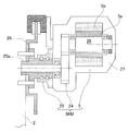
- the electric motor 5 may constitute an in-wheel motor drive device IWM.
- the left and right drive wheels 2, 2 (FIG. 1) are driven by independent electric motors 5, respectively.
- Each in-wheel motor drive device IWM has the electric motor 5, the reduction gear 24, and the wheel bearing 25, respectively, These are arrange
- a brake rotor 26 constituting a brake is fixed to the flange portion of the hub wheel 25a of the wheel bearing 25, and the brake rotor 26 rotates integrally with the drive wheel 2.
- the electric motor 5 is, for example, an embedded magnet type synchronous motor in which a permanent magnet is built in the core portion of the rotor 5a.
- the electric motor 5 is a motor in which a radial gap is provided between the stator 5 b fixed to the housing 27 and the rotor 5 a attached to the rotation output shaft 28.
- the in-wheel motor drive device IWM As the reducer 24 of the in-wheel motor drive device IWM, a cycloid type reducer, a planetary reducer, a parallel two-axis reducer, and other reducers can be applied. Instead, the in-wheel motor drive device IWM may be a so-called direct motor type that does not employ a reduction gear.
- the vehicle on which this motor drive device is mounted has two left and right rear wheels 2 and 2 independent by two electric motors 5 and 5 provided on the vehicle body 1.
- a two-motor on-board type that is driven in this manner may be used.
- a front-wheel drive type electric vehicle that drives the left and right front wheels in a 1-motor on-board format, a 2-motor on-board format, or an in-wheel motor drive format may be applied.
- a four-wheel drive type electric vehicle that drives the front, rear, left, and right wheels may be applied.
Landscapes
- Engineering & Computer Science (AREA)
- Power Engineering (AREA)
- Transportation (AREA)
- Mechanical Engineering (AREA)
- Electric Propulsion And Braking For Vehicles (AREA)
- Control Of Ac Motors In General (AREA)
Abstract
L'invention concerne un dispositif d'entraînement par moteur qui permet d'empêcher que le conducteur d'un véhicule pourvu d'un dispositif d'entraînement par moteur ne ressente de sensation désagréable lorsque le conducteur actionne un moyen d'actionnement d'accélérateur. Le dispositif d'entraînement par moteur selon l'invention comprend un moteur électrique (5), un moyen de détection de vitesse de véhicule (7) et un dispositif de commande (6). Le dispositif de commande (6) comprend une unité de commande électronique (ECU) (8), un moyen de commande de couple correspondant à la vitesse du véhicule (10) et une unité de commande de couple (11). Le moyen de commande de couple correspondant à la vitesse du véhicule (10) comprend une unité de réglage de la sensibilité d'accélérateur qui règle une instruction d'entraînement de sorte qu'une valeur d'instruction de couple réglée, transmise à l'unité de commande de couple (11) par le moyen de commande de couple correspondant à la vitesse du véhicule (10), lors de la réception d'un signal indiquant le degré maximal de fonctionnement du moyen d'actionnement d'accélérateur (12), correspond au couple maximal correspondant à la vitesse du véhicule pour la vitesse de véhicule actuelle, déterminé uniquement sur la base d'une relation entre la vitesse du véhicule et le couple maximal correspondant à la vitesse du véhicule, qui est fonction de la vitesse, et de sorte que la valeur d'instruction de couple réglée est proportionnelle au degré de fonctionnement du moyen d'actionnement d'accélérateur (12).
Applications Claiming Priority (2)
| Application Number | Priority Date | Filing Date | Title |
|---|---|---|---|
| JP2015-150469 | 2015-07-30 | ||
| JP2015150469A JP2017034785A (ja) | 2015-07-30 | 2015-07-30 | モータ駆動装置 |
Publications (1)
| Publication Number | Publication Date |
|---|---|
| WO2017018335A1 true WO2017018335A1 (fr) | 2017-02-02 |
Family
ID=57884819
Family Applications (1)
| Application Number | Title | Priority Date | Filing Date |
|---|---|---|---|
| PCT/JP2016/071507 Ceased WO2017018335A1 (fr) | 2015-07-30 | 2016-07-22 | Dispositif d'entraînement par moteur |
Country Status (2)
| Country | Link |
|---|---|
| JP (1) | JP2017034785A (fr) |
| WO (1) | WO2017018335A1 (fr) |
Cited By (3)
| Publication number | Priority date | Publication date | Assignee | Title |
|---|---|---|---|---|
| CN110562046A (zh) * | 2019-08-09 | 2019-12-13 | 武汉格罗夫氢能汽车有限公司 | 一种驾驶特性可调的氢能汽车实时交互系统及其控制方法 |
| CN112644500A (zh) * | 2019-10-09 | 2021-04-13 | 广州汽车集团股份有限公司 | 驾驶模式调整方法、装置、计算机设备及存储介质 |
| CN113085567A (zh) * | 2019-12-23 | 2021-07-09 | 博世汽车部件(苏州)有限公司 | 驱动扭矩控制方法和系统、电动骑行车辆及可读存储介质 |
Families Citing this family (1)
| Publication number | Priority date | Publication date | Assignee | Title |
|---|---|---|---|---|
| JP7279576B2 (ja) * | 2019-08-13 | 2023-05-23 | トヨタ車体株式会社 | 車載モータの制御装置 |
Citations (5)
| Publication number | Priority date | Publication date | Assignee | Title |
|---|---|---|---|---|
| JPH09193675A (ja) * | 1996-01-23 | 1997-07-29 | Aqueous Res:Kk | ハイブリッド車両 |
| JPH10325345A (ja) * | 1997-12-25 | 1998-12-08 | Aisin Aw Co Ltd | ハイブリッド車両 |
| JP2005348482A (ja) * | 2004-06-01 | 2005-12-15 | Fuji Heavy Ind Ltd | ハイブリッド車両の制御装置 |
| JP2007055535A (ja) * | 2005-08-26 | 2007-03-08 | Toyota Motor Corp | 自動車およびその制御方法 |
| WO2012066673A1 (fr) * | 2010-11-19 | 2012-05-24 | トヨタ自動車株式会社 | Dispositif de commande et procédé de commande pour véhicule à propulsion électrique |
-
2015
- 2015-07-30 JP JP2015150469A patent/JP2017034785A/ja active Pending
-
2016
- 2016-07-22 WO PCT/JP2016/071507 patent/WO2017018335A1/fr not_active Ceased
Patent Citations (5)
| Publication number | Priority date | Publication date | Assignee | Title |
|---|---|---|---|---|
| JPH09193675A (ja) * | 1996-01-23 | 1997-07-29 | Aqueous Res:Kk | ハイブリッド車両 |
| JPH10325345A (ja) * | 1997-12-25 | 1998-12-08 | Aisin Aw Co Ltd | ハイブリッド車両 |
| JP2005348482A (ja) * | 2004-06-01 | 2005-12-15 | Fuji Heavy Ind Ltd | ハイブリッド車両の制御装置 |
| JP2007055535A (ja) * | 2005-08-26 | 2007-03-08 | Toyota Motor Corp | 自動車およびその制御方法 |
| WO2012066673A1 (fr) * | 2010-11-19 | 2012-05-24 | トヨタ自動車株式会社 | Dispositif de commande et procédé de commande pour véhicule à propulsion électrique |
Cited By (4)
| Publication number | Priority date | Publication date | Assignee | Title |
|---|---|---|---|---|
| CN110562046A (zh) * | 2019-08-09 | 2019-12-13 | 武汉格罗夫氢能汽车有限公司 | 一种驾驶特性可调的氢能汽车实时交互系统及其控制方法 |
| CN112644500A (zh) * | 2019-10-09 | 2021-04-13 | 广州汽车集团股份有限公司 | 驾驶模式调整方法、装置、计算机设备及存储介质 |
| CN112644500B (zh) * | 2019-10-09 | 2022-09-06 | 广州汽车集团股份有限公司 | 驾驶模式调整方法、装置、计算机设备及存储介质 |
| CN113085567A (zh) * | 2019-12-23 | 2021-07-09 | 博世汽车部件(苏州)有限公司 | 驱动扭矩控制方法和系统、电动骑行车辆及可读存储介质 |
Also Published As
| Publication number | Publication date |
|---|---|
| JP2017034785A (ja) | 2017-02-09 |
Similar Documents
| Publication | Publication Date | Title |
|---|---|---|
| JP6472626B2 (ja) | 車両の横滑り防止制御装置 | |
| US9855858B2 (en) | Control device for electric vehicle | |
| US10017075B2 (en) | Device for controlling electric automobile | |
| JP6534509B2 (ja) | 車輪独立駆動式車両の駆動制御装置 | |
| WO2017204070A1 (fr) | Dispositif de commande de virage de véhicule | |
| US20180345796A1 (en) | Drive control device for vehicle with independently driven wheels | |
| JP2017005899A (ja) | 車輪独立駆動式車両の駆動制御装置 | |
| JP2015104295A (ja) | 電気自動車の制御装置 | |
| US9586484B2 (en) | Electric-vehicle control device | |
| WO2016125686A1 (fr) | Dispositif de commande de couple de freinage/entraînement de véhicule | |
| US9956890B2 (en) | Device for controlling electric automobile | |
| JP2017034785A (ja) | モータ駆動装置 | |
| WO2016043077A1 (fr) | Dispositif de commande d'entraînement de véhicule | |
| JP2016073061A (ja) | 電気自動車の制御装置 | |
| JP5915349B2 (ja) | 電動車両の制振制御装置 | |
| JP2004023943A (ja) | 電気自動車の後退抑制制御装置 | |
| JP2013251988A (ja) | モータジェネレータ制御装置 | |
| JP5496294B2 (ja) | 車両共振抑制制御装置 | |
| JP6663724B2 (ja) | 電動モータ装置 | |
| JP6649478B2 (ja) | 電動車両 | |
| JP2010130775A (ja) | 電動車両のサウンド制御装置 | |
| JP6772501B2 (ja) | 自動車 | |
| JP6137045B2 (ja) | 車両の駆動電動機制御装置 | |
| JP2016220271A (ja) | 電気自動車の制御装置 |
Legal Events
| Date | Code | Title | Description |
|---|---|---|---|
| 121 | Ep: the epo has been informed by wipo that ep was designated in this application |
Ref document number: 16830440 Country of ref document: EP Kind code of ref document: A1 |
|
| NENP | Non-entry into the national phase |
Ref country code: DE |
|
| 122 | Ep: pct application non-entry in european phase |
Ref document number: 16830440 Country of ref document: EP Kind code of ref document: A1 |