WO2017018348A1 - Dispositif d'embrayage de ventilateur à commande externe - Google Patents
Dispositif d'embrayage de ventilateur à commande externe Download PDFInfo
- Publication number
- WO2017018348A1 WO2017018348A1 PCT/JP2016/071578 JP2016071578W WO2017018348A1 WO 2017018348 A1 WO2017018348 A1 WO 2017018348A1 JP 2016071578 W JP2016071578 W JP 2016071578W WO 2017018348 A1 WO2017018348 A1 WO 2017018348A1
- Authority
- WO
- WIPO (PCT)
- Prior art keywords
- valve member
- armature
- oil
- leaf spring
- clutch device
- Prior art date
- Legal status (The legal status is an assumption and is not a legal conclusion. Google has not performed a legal analysis and makes no representation as to the accuracy of the status listed.)
- Ceased
Links
Images


Classifications
-
- F—MECHANICAL ENGINEERING; LIGHTING; HEATING; WEAPONS; BLASTING
- F16—ENGINEERING ELEMENTS AND UNITS; GENERAL MEASURES FOR PRODUCING AND MAINTAINING EFFECTIVE FUNCTIONING OF MACHINES OR INSTALLATIONS; THERMAL INSULATION IN GENERAL
- F16D—COUPLINGS FOR TRANSMITTING ROTATION; CLUTCHES; BRAKES
- F16D35/00—Fluid clutches in which the clutching is predominantly obtained by fluid adhesion
- F16D35/02—Fluid clutches in which the clutching is predominantly obtained by fluid adhesion with rotary working chambers and rotary reservoirs, e.g. in one coupling part
- F16D35/021—Fluid clutches in which the clutching is predominantly obtained by fluid adhesion with rotary working chambers and rotary reservoirs, e.g. in one coupling part actuated by valves
- F16D35/024—Fluid clutches in which the clutching is predominantly obtained by fluid adhesion with rotary working chambers and rotary reservoirs, e.g. in one coupling part actuated by valves the valve being actuated electrically, e.g. by an electromagnet
-
- F—MECHANICAL ENGINEERING; LIGHTING; HEATING; WEAPONS; BLASTING
- F16—ENGINEERING ELEMENTS AND UNITS; GENERAL MEASURES FOR PRODUCING AND MAINTAINING EFFECTIVE FUNCTIONING OF MACHINES OR INSTALLATIONS; THERMAL INSULATION IN GENERAL
- F16D—COUPLINGS FOR TRANSMITTING ROTATION; CLUTCHES; BRAKES
- F16D35/00—Fluid clutches in which the clutching is predominantly obtained by fluid adhesion
- F16D35/02—Fluid clutches in which the clutching is predominantly obtained by fluid adhesion with rotary working chambers and rotary reservoirs, e.g. in one coupling part
-
- F—MECHANICAL ENGINEERING; LIGHTING; HEATING; WEAPONS; BLASTING
- F01—MACHINES OR ENGINES IN GENERAL; ENGINE PLANTS IN GENERAL; STEAM ENGINES
- F01P—COOLING OF MACHINES OR ENGINES IN GENERAL; COOLING OF INTERNAL-COMBUSTION ENGINES
- F01P5/00—Pumping cooling-air or liquid coolants
- F01P5/02—Pumping cooling-air; Arrangements of cooling-air pumps, e.g. fans or blowers
- F01P5/04—Pump-driving arrangements
-
- F—MECHANICAL ENGINEERING; LIGHTING; HEATING; WEAPONS; BLASTING
- F01—MACHINES OR ENGINES IN GENERAL; ENGINE PLANTS IN GENERAL; STEAM ENGINES
- F01P—COOLING OF MACHINES OR ENGINES IN GENERAL; COOLING OF INTERNAL-COMBUSTION ENGINES
- F01P7/00—Controlling of coolant flow
- F01P7/02—Controlling of coolant flow the coolant being cooling-air
- F01P7/04—Controlling of coolant flow the coolant being cooling-air by varying pump speed, e.g. by changing pump-drive gear ratio
- F01P7/042—Controlling of coolant flow the coolant being cooling-air by varying pump speed, e.g. by changing pump-drive gear ratio using fluid couplings
-
- F—MECHANICAL ENGINEERING; LIGHTING; HEATING; WEAPONS; BLASTING
- F01—MACHINES OR ENGINES IN GENERAL; ENGINE PLANTS IN GENERAL; STEAM ENGINES
- F01P—COOLING OF MACHINES OR ENGINES IN GENERAL; COOLING OF INTERNAL-COMBUSTION ENGINES
- F01P7/00—Controlling of coolant flow
- F01P7/02—Controlling of coolant flow the coolant being cooling-air
- F01P7/08—Controlling of coolant flow the coolant being cooling-air by cutting in or out of pumps
-
- F—MECHANICAL ENGINEERING; LIGHTING; HEATING; WEAPONS; BLASTING
- F01—MACHINES OR ENGINES IN GENERAL; ENGINE PLANTS IN GENERAL; STEAM ENGINES
- F01P—COOLING OF MACHINES OR ENGINES IN GENERAL; COOLING OF INTERNAL-COMBUSTION ENGINES
- F01P7/00—Controlling of coolant flow
- F01P7/02—Controlling of coolant flow the coolant being cooling-air
- F01P7/08—Controlling of coolant flow the coolant being cooling-air by cutting in or out of pumps
- F01P7/081—Controlling of coolant flow the coolant being cooling-air by cutting in or out of pumps using clutches, e.g. electro-magnetic or induction clutches
Definitions
- the present invention generally relates to an externally controlled fan / clutch device that controls the rotation of a fan for cooling an engine in an automobile or the like by following a temperature change or a rotation change around the outside.
- a non-magnetic case supported via a bearing on a rotating shaft (shaft) to which a drive disk is fixed and a cover attached to the case And at least one oil circulation communicating with a torque transmission gap on a side wall surface of an oil sump chamber provided with a hollow inside of the drive disk.
- a valve member having a flow path (oil supply port) and having magnetism for opening and closing the oil circulation flow path, and the valve member is actuated by an electromagnet so that a torque transmission gap formed between the drive side and the driven side
- a system that controls the rotational torque transmission from the drive side to the driven side by increasing or decreasing the effective contact area of the oil (viscous fluid).
- an externally controlled fan / clutch device for example, by energizing an electromagnet fixed on the rotating shaft body side, a valve member provided on a drive disk or a sealer cage is operated via an armature, and an oil circulation flow passage
- an externally controlled fan / clutch device that controls opening and closing of the (oil supply port) from the outside, and the structure is such that the magnetic flux generated by excitation of the electromagnet coil passes through the magnetic path of the rotating shaft body made of a magnetic material with high permeability.
- a magnetic circuit (magnetic loop) that transmits to the armature of the valve member consisting of a leaf spring and returns to the electromagnet is constructed, and the valve member inside the clutch device is operated by the electromagnet to control the flow rate of torque transmission oil. (Refer to patent document 1 etc.).
- the above-described conventional externally controlled fan / clutch device has the following drawbacks. That is, in the conventional externally controlled fan / clutch device, the amount of oil supplied to the torque transmission chamber is controlled by the valve member. To increase the amount of oil supplied, the stroke of the valve member (opening / closing operation amount or movement) It is necessary to increase the amount.
- the valve member for oil supply that opens and closes the oil circulation passage (oil supply port) provided in the drive disk and the sealer cage has an integral (single) armature on the back of the single leaf spring. The oil supply amount is increased because the leaf spring base end is attached to the drive disk or sealer cage so that the armature of the valve member is located in the vicinity of the rotating shaft body.
- the present invention has been made to solve the problems of the conventional externally controlled fan / clutch device described above, and by changing the armature of the valve member from the conventional integral type to a plurality of divided types, It is an object of the present invention to provide an externally controlled fan / clutch device with improved performance.
- the externally controlled fan / clutch device easily secures the stroke of the valve member by increasing the bending point of the leaf spring by making the armature of the valve member into a plurality of divided types in order to improve the characteristics of the solenoid valve.
- the stress of the leaf spring can be dispersed, and the gist thereof is a non-magnetic case supported via a bearing on a rotating shaft body to which a drive disk is fixed, and the case.
- At least one oil circulation which is provided with a torque transmission chamber and an oil reservoir chamber in which a drive disk is built inside a seal box made of a cover attached to the case, and which communicates with a torque transmission gap on a side wall surface of the oil reservoir chamber.
- a valve member having a flow path and having magnetism for opening and closing the oil circulation flow path, the valve member having a structure in which an armature is attached to a leaf spring having one end attached to the seal box And an electromagnet supported on the rotating shaft through a bearing, a ring-shaped magnetic member on the outer periphery of the rotating shaft, and the valve member is operated by the electromagnet to control the opening and closing of the oil circulation passage.
- the armature attached to the leaf spring of the valve member is divided into a plurality in the direction from the base end side to the swing end side of the leaf spring to provide a plurality of bending points of the leaf spring. It is characterized by having a structure.
- the armature of the valve member is divided into a plurality of types, and a plurality of bending points are provided on the leaf spring, so that the stress of the leaf spring can be dispersed and the oil supply Even if the stroke of the valve member is set large to increase the amount, the valve member can be operated without increasing the attractive force of the armature by the electromagnet. Therefore, according to the present invention, even if the leaf spring of the valve member is far away from the oil circulation passage, the stress of the leaf spring does not increase or the armature's attractive force by the electromagnet does not become insufficient. A stable valve opening / closing operation can be obtained with this electromagnet, and it is not necessary to use an electromagnet having a large magnetic force in order to increase the attraction force of the leaf spring, thereby reducing the size and weight of the fan / clutch device.
- FIG. 1A is a schematic plan view
- FIG. 1B is a schematic longitudinal sectional view along line bb in FIG. It is.
- FIG. 1A is a schematic plan view
- FIG. 1B is a schematic longitudinal sectional view along line bb in FIG. It is.
- FIG. 1A is a schematic plan view
- FIG. 1B is a schematic longitudinal sectional view along line bb in FIG. It is.
- FIG. 1A is a schematic plan view
- FIG. 1B is a schematic longitudinal sectional view along line bb in FIG. It is.
- the externally controlled fan / clutch device shown in FIG. 1 includes a rotating shaft body (driving shaft) 1 that is rotated by driving of a driving portion (engine), and a case 2-1 and a cover 2-2 via a bearing 13.
- the sealer cage 2 is supported, and a drive disk 3 fixed to the rotary shaft 1 is housed in a torque transmission chamber 6 in the sealer cage 2.
- the case 2-1 includes an oil flow passage 9 communicating with the torque transmission chamber 6 and an oil sump chamber 5 provided with a hollow inside, and the oil sump chamber (oil storage chamber) 5 has an upper portion of the oil sump chamber (oil storage chamber) 5.
- An oil circulation flow passage (oil supply port) 8 communicating with the flow passage 9 is provided, and the oil in the oil sump chamber 5 transmits torque via the oil circulation flow passage (oil supply port) 8 and the oil circulation space 9.
- the structure is supplied to the chamber 6.
- An oil supply valve member 10 that opens and closes the oil circulation passage 8 includes a leaf spring 10-1 and an armature 10-2, and the armature 10-2 of the valve member is positioned in the vicinity of the rotary shaft 1. Further, the base end portion of the leaf spring 10-1 that is externally fitted to the rotary shaft 1 is fixed to a mounting portion 11 provided on the back side of the case in the oil flow passage 9 with a screw or the like.
- a ring-shaped electromagnet 16 is supported by a ring-shaped electromagnet support 17 supported on the rotary shaft 1 via a bearing 14 on the drive unit side of the sealer cage 2, and the electromagnet 16 and the valve member are supported.
- a first magnetic ring 18 is disposed on the outer periphery of the base portion of the case 2-1 that is externally fitted to the outer periphery of the rotating shaft 1 between the ten, and the first magnetic body is interposed between the electromagnet support 17 and the case 2-1.
- a second magnetic ring 19 is fixed so as to surround the ring 18.
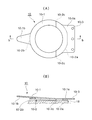
- the conventional valve member 10 ′ (armature integrated type) shown in FIGS. 3 (A) and 3 (B) is composed of a leaf spring 10′-1 and an armature 10′-2 whose body is annular, and the leaf spring 10 ′.
- '-1 is formed with a triangular protrusion 10'-1b at the end opposite to the base end 10'-1a, and an integral annular armature 10' on the rear surface of the annular portion of the leaf spring 10'-1. -2 is attached.
- the leaf spring base end portion 10′-1a is externally fitted to the rotary shaft 1 so that the armature 10′-2 of the valve member is positioned in the vicinity of the rotary shaft 1. And it is fixed to the mounting portion 11 provided on the back side of the case with a screw or the like.
- 10'-3 is a mounting hole.
- the leaf spring base end portion 10'-1a is fixed when the electromagnet 16 is not excited.
- the stroke of the valve member is increased to increase the opening amount in order to increase the oil supply amount.
- the triangular projection 10′-1b of the leaf spring is greatly separated from the oil circulation passage, and the attractive force of the armature 10′-2 by the electromagnet 16 is insufficient, or the stress of the leaf spring 10′-1 is reduced. Inconveniences such as increased valve opening / closing operation become unstable. That is, the conventional valve member 10 ′ uses an integral (one piece) armature 10 ′-2, so that the valve member 10 ′ has one bending point.
- the valve member 10 of the present invention is configured to disperse the stress of the leaf spring by increasing the bending point of the leaf spring by making the armature, which has conventionally been an integral type, into a plurality of divided types.
- the structure is the same as that of the conventional valve member 10 ′ shown in FIGS. 3A and 3B except that a multi-segment armature is adopted as shown in FIGS. 2A and 2B.
- the valve member 10 of the present invention includes a leaf spring 10-1 having a ring-shaped main body and a triangular protrusion 10-1b formed on the end opposite to the base end 10-1a, and a split armature.
- the armature 10-2 divided into two parts 10-2b is attached to the back surface of the leaf spring 10-1, and the divided portions 10-2c of the two armature divided pieces 10-2a, 10-2b are attached to the leaf spring 10-.
- 1 is another bending point.
- the valve member 10 of the present invention adopting this split-type armature 10-2 is externally fitted to the rotary shaft 1 so that the armature 10-2 of the valve member is positioned in the vicinity of the rotary shaft 1 as described above.
- the base end of the leaf spring 10-1 is fixed to a mounting portion 11 provided on the back side of the case in the oil circulation space 9 with a screw or the like.
- reference numeral 10-3 denotes a mounting hole.
- the armature 10-2 acts as an oil circulation flow path by the action of the leaf spring 10-1.
- the oil circulation flow passage 8 is opened by separating from the oil flow 8, the oil reservoir chamber 5 and the torque transmission chamber 6 communicate with each other, and the oil in the oil reservoir chamber 5 is supplied to the torque transmission chamber 6.
- the ten leaf springs 10-1 open with the split portions 10-2c of the two armature split pieces 10-2a, 10-2b as bending points, and therefore the leaf spring base of the two armature split pieces 10-2a, 10-2b.
- the armature divided piece 10-2a on the side of the end 10-1a is substantially in contact with the second magnetic ring 19.
- the electromagnet 16 when the electromagnet 16 is ON (excitation), the armature 10-2 is attracted against the leaf spring 10-1, so that the oil is absorbed by the triangular protrusion 10-1b of the leaf spring 10-1.
- the circulation flow path 8 is closed and the supply to the oil torque transmission chamber 6 in the oil sump chamber 5 is shut off.
- the leaf spring 10-1 of the valve member 10 has two armature divided pieces 10-2a, Since the dividing portion 10-2c of 10-2b is closed at the bending point, the attractive force of the armature can be reduced as compared with the case where the base end portion of the leaf spring 10-1 is the bending point. Therefore, for example, even if the stroke of the valve member 10 is set large to increase the amount of oil supplied to the torque transmission chamber, the valve member 10 can be operated without increasing the attractive force of the armature 10-2 by the electromagnet 16. It becomes. Further, by further dividing the armature 10-2 to increase the bending point of the leaf spring 10-1, the stress acting on the leaf spring 10-1 can be further dispersed.
- the stress of the leaf spring does not increase or the armature's attractive force by the electromagnet does not become insufficient.
- Stable valve opening and closing operation can be obtained with ordinary electromagnets, and it is not necessary to use electromagnets with high magnetic force to increase the attraction force of the leaf springs, thereby reducing the size and weight of externally controlled fan and clutch devices. it can.
- the externally controlled fan / clutch device is applied to a type in which an oil sump chamber is provided in the case of the seal box, but the structure of the oil disc chamber provided on the drive disk side is described. Needless to say, the present invention can be applied to an externally controlled fan / clutch device or the like.
Landscapes
- Engineering & Computer Science (AREA)
- General Engineering & Computer Science (AREA)
- Mechanical Engineering (AREA)
- Chemical & Material Sciences (AREA)
- Combustion & Propulsion (AREA)
- Physics & Mathematics (AREA)
- Electromagnetism (AREA)
- Magnetically Actuated Valves (AREA)
Abstract
Priority Applications (4)
| Application Number | Priority Date | Filing Date | Title |
|---|---|---|---|
| EP16830453.3A EP3330561B1 (fr) | 2015-07-27 | 2016-07-22 | Dispositif d'embrayage de ventilateur à commande externe |
| CN201680043628.7A CN107923453B (zh) | 2015-07-27 | 2016-07-22 | 外部控制式风扇-离合器装置 |
| US15/747,177 US10670089B2 (en) | 2015-07-27 | 2016-07-22 | External control type fan clutch device |
| KR1020187003665A KR101983519B1 (ko) | 2015-07-27 | 2016-07-22 | 외부 제어식 팬·클러치 장치 |
Applications Claiming Priority (2)
| Application Number | Priority Date | Filing Date | Title |
|---|---|---|---|
| JP2015-148109 | 2015-07-27 | ||
| JP2015148109A JP6562749B2 (ja) | 2015-07-27 | 2015-07-27 | 外部制御式ファン・クラッチ装置 |
Publications (1)
| Publication Number | Publication Date |
|---|---|
| WO2017018348A1 true WO2017018348A1 (fr) | 2017-02-02 |
Family
ID=57884393
Family Applications (1)
| Application Number | Title | Priority Date | Filing Date |
|---|---|---|---|
| PCT/JP2016/071578 Ceased WO2017018348A1 (fr) | 2015-07-27 | 2016-07-22 | Dispositif d'embrayage de ventilateur à commande externe |
Country Status (6)
| Country | Link |
|---|---|
| US (1) | US10670089B2 (fr) |
| EP (1) | EP3330561B1 (fr) |
| JP (1) | JP6562749B2 (fr) |
| KR (1) | KR101983519B1 (fr) |
| CN (1) | CN107923453B (fr) |
| WO (1) | WO2017018348A1 (fr) |
Families Citing this family (5)
| Publication number | Priority date | Publication date | Assignee | Title |
|---|---|---|---|---|
| KR101958274B1 (ko) * | 2018-10-16 | 2019-03-14 | 주식회사 이엠티 | 밸브 인력이 보강된 엔진냉각제어장치 |
| CN109458406B (zh) * | 2018-10-16 | 2024-06-11 | 东风马勒热系统有限公司 | 一种电控硅油离合器阀杆及电控硅油离合器 |
| CN113503208B (zh) * | 2021-07-30 | 2024-10-18 | 华纳圣龙(宁波)有限公司 | 一种双阀电控硅油风扇离合器 |
| CN114753919A (zh) * | 2022-04-24 | 2022-07-15 | 东风马勒热系统有限公司 | 适配电控硅油水泵的控制阀杆 |
| CN116336102B (zh) * | 2023-03-29 | 2025-10-24 | 潍柴动力股份有限公司 | 一种电控硅油风扇离合器及其控制方法 |
Citations (2)
| Publication number | Priority date | Publication date | Assignee | Title |
|---|---|---|---|---|
| JPS5194562U (fr) * | 1975-01-28 | 1976-07-29 | ||
| JP2014238111A (ja) * | 2013-06-06 | 2014-12-18 | 臼井国際産業株式会社 | 外部制御式ファン・クラッチ装置 |
Family Cites Families (11)
| Publication number | Priority date | Publication date | Assignee | Title |
|---|---|---|---|---|
| JPS5439631Y2 (fr) * | 1974-08-09 | 1979-11-22 | ||
| JPS5122744A (ja) | 1974-08-19 | 1976-02-23 | Dainichiseika Color Chem | Horiorefuinyochakushokuzai |
| DE50101324D1 (de) * | 2001-04-06 | 2004-02-19 | Borgwarner Inc | Flüssigkeitsreibungskupplung |
| JP4007489B2 (ja) * | 2002-02-14 | 2007-11-14 | 臼井国際産業株式会社 | 外部制御式ファンカップリング装置の制御方法 |
| JP4353396B2 (ja) * | 2002-10-22 | 2009-10-28 | 臼井国際産業株式会社 | 外部制御式ファン・カップリング装置 |
| JP2004162911A (ja) * | 2002-10-22 | 2004-06-10 | Usui Kokusai Sangyo Kaisha Ltd | 外部制御式ファン・カップリング装置 |
| CN100434739C (zh) * | 2002-10-22 | 2008-11-19 | 臼井国际产业株式会社 | 外部控制型风扇耦合装置 |
| JP4813868B2 (ja) * | 2004-11-09 | 2011-11-09 | 臼井国際産業株式会社 | 外部制御式ファン・カップリング装置 |
| EP2606251B1 (fr) * | 2010-08-19 | 2018-05-30 | Horton, Inc. | Ensemble de soupape d'embrayage visqueux |
| CN201730665U (zh) * | 2010-08-26 | 2011-02-02 | 五龙控股有限公司 | 一种用于硅油风扇离合器的阀片机构 |
| JP6391141B2 (ja) * | 2014-01-31 | 2018-09-19 | 臼井国際産業株式会社 | 外部制御式ファン・クラッチ装置 |
-
2015
- 2015-07-27 JP JP2015148109A patent/JP6562749B2/ja not_active Expired - Fee Related
-
2016
- 2016-07-22 KR KR1020187003665A patent/KR101983519B1/ko not_active Expired - Fee Related
- 2016-07-22 WO PCT/JP2016/071578 patent/WO2017018348A1/fr not_active Ceased
- 2016-07-22 EP EP16830453.3A patent/EP3330561B1/fr not_active Not-in-force
- 2016-07-22 CN CN201680043628.7A patent/CN107923453B/zh not_active Expired - Fee Related
- 2016-07-22 US US15/747,177 patent/US10670089B2/en not_active Expired - Fee Related
Patent Citations (2)
| Publication number | Priority date | Publication date | Assignee | Title |
|---|---|---|---|---|
| JPS5194562U (fr) * | 1975-01-28 | 1976-07-29 | ||
| JP2014238111A (ja) * | 2013-06-06 | 2014-12-18 | 臼井国際産業株式会社 | 外部制御式ファン・クラッチ装置 |
Also Published As
| Publication number | Publication date |
|---|---|
| CN107923453A (zh) | 2018-04-17 |
| EP3330561B1 (fr) | 2019-06-05 |
| US20180216675A1 (en) | 2018-08-02 |
| US10670089B2 (en) | 2020-06-02 |
| KR101983519B1 (ko) | 2019-09-10 |
| JP2017026114A (ja) | 2017-02-02 |
| EP3330561A1 (fr) | 2018-06-06 |
| KR20180028479A (ko) | 2018-03-16 |
| EP3330561A4 (fr) | 2019-01-02 |
| CN107923453B (zh) | 2019-10-25 |
| JP6562749B2 (ja) | 2019-08-21 |
Similar Documents
| Publication | Publication Date | Title |
|---|---|---|
| KR101586915B1 (ko) | 외부 제어식 팬 클러치 장치 | |
| JP6562749B2 (ja) | 外部制御式ファン・クラッチ装置 | |
| JP6391141B2 (ja) | 外部制御式ファン・クラッチ装置 | |
| US6550596B2 (en) | Externally controlled fan coupling device | |
| US6915888B2 (en) | External control type fan-coupling device | |
| JP2015143547A5 (fr) | ||
| JP4813869B2 (ja) | 外部制御式ファン・カップリング装置 | |
| JP6264890B2 (ja) | ウォーターポンプ | |
| JP2007120645A (ja) | 外部制御式流体継手 | |
| JP4353396B2 (ja) | 外部制御式ファン・カップリング装置 | |
| JP2002081466A (ja) | 外部制御式ファン・カップリング装置 | |
| JP4353397B2 (ja) | 外部制御式ファン・カップリング装置 | |
| JP6888451B2 (ja) | 電磁弁 | |
| CN222687311U (zh) | 机械密封结构及压缩机 | |
| US20170370477A1 (en) | External control type fluid coupling | |
| JP2002013556A (ja) | 外部制御式ファン・カップリング装置 | |
| JP6963469B2 (ja) | バルブ装置 | |
| JP2000130632A (ja) | 電磁弁 | |
| US20190257373A1 (en) | Fan-coupling device with unitary magnetic pole construction | |
| JP2008115928A (ja) | 粘性流体継手装置 |
Legal Events
| Date | Code | Title | Description |
|---|---|---|---|
| 121 | Ep: the epo has been informed by wipo that ep was designated in this application |
Ref document number: 16830453 Country of ref document: EP Kind code of ref document: A1 |
|
| WWE | Wipo information: entry into national phase |
Ref document number: 15747177 Country of ref document: US |
|
| NENP | Non-entry into the national phase |
Ref country code: DE |
|
| ENP | Entry into the national phase |
Ref document number: 20187003665 Country of ref document: KR Kind code of ref document: A |
|
| WWE | Wipo information: entry into national phase |
Ref document number: 2016830453 Country of ref document: EP |