WO2017018375A1 - 導光板及びこれを用いた積層導光板 - Google Patents
導光板及びこれを用いた積層導光板 Download PDFInfo
- Publication number
- WO2017018375A1 WO2017018375A1 PCT/JP2016/071715 JP2016071715W WO2017018375A1 WO 2017018375 A1 WO2017018375 A1 WO 2017018375A1 JP 2016071715 W JP2016071715 W JP 2016071715W WO 2017018375 A1 WO2017018375 A1 WO 2017018375A1
- Authority
- WO
- WIPO (PCT)
- Prior art keywords
- light guide
- less
- guide plate
- glass plate
- glass
- Prior art date
- Legal status (The legal status is an assumption and is not a legal conclusion. Google has not performed a legal analysis and makes no representation as to the accuracy of the status listed.)
- Ceased
Links
Images
Classifications
-
- G—PHYSICS
- G02—OPTICS
- G02B—OPTICAL ELEMENTS, SYSTEMS OR APPARATUS
- G02B6/00—Light guides; Structural details of arrangements comprising light guides and other optical elements, e.g. couplings
- G02B6/0001—Light guides; Structural details of arrangements comprising light guides and other optical elements, e.g. couplings specially adapted for lighting devices or systems
- G02B6/0011—Light guides; Structural details of arrangements comprising light guides and other optical elements, e.g. couplings specially adapted for lighting devices or systems the light guides being planar or of plate-like form
- G02B6/0065—Manufacturing aspects; Material aspects
-
- C—CHEMISTRY; METALLURGY
- C03—GLASS; MINERAL OR SLAG WOOL
- C03C—CHEMICAL COMPOSITION OF GLASSES, GLAZES OR VITREOUS ENAMELS; SURFACE TREATMENT OF GLASS; SURFACE TREATMENT OF FIBRES OR FILAMENTS MADE FROM GLASS, MINERALS OR SLAGS; JOINING GLASS TO GLASS OR OTHER MATERIALS
- C03C3/00—Glass compositions
- C03C3/04—Glass compositions containing silica
- C03C3/062—Glass compositions containing silica with less than 40% silica by weight
-
- C—CHEMISTRY; METALLURGY
- C03—GLASS; MINERAL OR SLAG WOOL
- C03C—CHEMICAL COMPOSITION OF GLASSES, GLAZES OR VITREOUS ENAMELS; SURFACE TREATMENT OF GLASS; SURFACE TREATMENT OF FIBRES OR FILAMENTS MADE FROM GLASS, MINERALS OR SLAGS; JOINING GLASS TO GLASS OR OTHER MATERIALS
- C03C3/00—Glass compositions
- C03C3/04—Glass compositions containing silica
- C03C3/076—Glass compositions containing silica with 40% to 90% silica, by weight
- C03C3/078—Glass compositions containing silica with 40% to 90% silica, by weight containing an oxide of a divalent metal, e.g. an oxide of zinc
-
- C—CHEMISTRY; METALLURGY
- C03—GLASS; MINERAL OR SLAG WOOL
- C03C—CHEMICAL COMPOSITION OF GLASSES, GLAZES OR VITREOUS ENAMELS; SURFACE TREATMENT OF GLASS; SURFACE TREATMENT OF FIBRES OR FILAMENTS MADE FROM GLASS, MINERALS OR SLAGS; JOINING GLASS TO GLASS OR OTHER MATERIALS
- C03C3/00—Glass compositions
- C03C3/04—Glass compositions containing silica
- C03C3/076—Glass compositions containing silica with 40% to 90% silica, by weight
- C03C3/083—Glass compositions containing silica with 40% to 90% silica, by weight containing aluminium oxide or an iron compound
- C03C3/085—Glass compositions containing silica with 40% to 90% silica, by weight containing aluminium oxide or an iron compound containing an oxide of a divalent metal
- C03C3/087—Glass compositions containing silica with 40% to 90% silica, by weight containing aluminium oxide or an iron compound containing an oxide of a divalent metal containing calcium oxide, e.g. common sheet or container glass
-
- G—PHYSICS
- G02—OPTICS
- G02B—OPTICAL ELEMENTS, SYSTEMS OR APPARATUS
- G02B1/00—Optical elements characterised by the material of which they are made; Optical coatings for optical elements
-
- G—PHYSICS
- G02—OPTICS
- G02B—OPTICAL ELEMENTS, SYSTEMS OR APPARATUS
- G02B27/00—Optical systems or apparatus not provided for by any of the groups G02B1/00 - G02B26/00, G02B30/00
- G02B27/01—Head-up displays
- G02B27/017—Head mounted
-
- G—PHYSICS
- G02—OPTICS
- G02B—OPTICAL ELEMENTS, SYSTEMS OR APPARATUS
- G02B27/00—Optical systems or apparatus not provided for by any of the groups G02B1/00 - G02B26/00, G02B30/00
- G02B27/02—Viewing or reading apparatus
-
- G—PHYSICS
- G02—OPTICS
- G02B—OPTICAL ELEMENTS, SYSTEMS OR APPARATUS
- G02B6/00—Light guides; Structural details of arrangements comprising light guides and other optical elements, e.g. couplings
-
- G—PHYSICS
- G02—OPTICS
- G02B—OPTICAL ELEMENTS, SYSTEMS OR APPARATUS
- G02B6/00—Light guides; Structural details of arrangements comprising light guides and other optical elements, e.g. couplings
- G02B6/0001—Light guides; Structural details of arrangements comprising light guides and other optical elements, e.g. couplings specially adapted for lighting devices or systems
- G02B6/0011—Light guides; Structural details of arrangements comprising light guides and other optical elements, e.g. couplings specially adapted for lighting devices or systems the light guides being planar or of plate-like form
- G02B6/0013—Means for improving the coupling-in of light from the light source into the light guide
- G02B6/0015—Means for improving the coupling-in of light from the light source into the light guide provided on the surface of the light guide or in the bulk of it
- G02B6/0016—Grooves, prisms, gratings, scattering particles or rough surfaces
-
- G—PHYSICS
- G02—OPTICS
- G02B—OPTICAL ELEMENTS, SYSTEMS OR APPARATUS
- G02B6/00—Light guides; Structural details of arrangements comprising light guides and other optical elements, e.g. couplings
- G02B6/0001—Light guides; Structural details of arrangements comprising light guides and other optical elements, e.g. couplings specially adapted for lighting devices or systems
- G02B6/0011—Light guides; Structural details of arrangements comprising light guides and other optical elements, e.g. couplings specially adapted for lighting devices or systems the light guides being planar or of plate-like form
- G02B6/0013—Means for improving the coupling-in of light from the light source into the light guide
- G02B6/0023—Means for improving the coupling-in of light from the light source into the light guide provided by one optical element, or plurality thereof, placed between the light guide and the light source, or around the light source
- G02B6/0031—Reflecting element, sheet or layer
-
- G—PHYSICS
- G02—OPTICS
- G02B—OPTICAL ELEMENTS, SYSTEMS OR APPARATUS
- G02B6/00—Light guides; Structural details of arrangements comprising light guides and other optical elements, e.g. couplings
- G02B6/0001—Light guides; Structural details of arrangements comprising light guides and other optical elements, e.g. couplings specially adapted for lighting devices or systems
- G02B6/0011—Light guides; Structural details of arrangements comprising light guides and other optical elements, e.g. couplings specially adapted for lighting devices or systems the light guides being planar or of plate-like form
- G02B6/0075—Arrangements of multiple light guides
- G02B6/0076—Stacked arrangements of multiple light guides of the same or different cross-sectional area
Definitions
- the present invention relates to a light guide plate and a laminated light guide plate using the same, and more particularly to a light guide plate suitable for a head mounted display, a 3D projection device, and the like, and a laminated light guide plate using the same.
- Acrylic resin is mainly used as the light guide plate material.
- the acrylic resin has a low refractive index nd (about 1.49), it is difficult to increase the degree of freedom in optical design. As a result, it is difficult for the acrylic resin to increase the resolution of the display image.
- the head-mounted display needs to be attached to the head, it is required to be lightweight.
- the present invention has been made in view of the above circumstances, and its technical problem is to devise a light guide plate that contributes to improving the resolution of a display image and reducing the weight of the device.
- the present inventors have found that the above technical problem can be solved by thinning a high refractive index glass plate and using it for a light guide plate, and propose the present invention.
- the light guide plate of the present invention is a light guide plate including a glass plate, wherein the refractive index nd of the glass plate is 1.56 or more, and the thickness of the glass plate is 1.0 mm or less.
- refractive index nd refers to a value measured using a refractive index measuring instrument (for example, a refractive index measuring instrument KPR-2000 manufactured by Shimadzu Corporation).
- the light guide plate of the present invention includes a glass plate.
- the glass plate has a high internal transmittance, is less likely to be scratched than an acrylic resin, and has rigidity.
- the refractive index nd of the glass plate is 1.56 or more. If the refractive index nd of the glass plate is regulated to 1.56 or more, the degree of freedom in optical design of the light guide plate can be increased.
- the light guide plate of the present invention has a glass plate thickness of 1.0 mm or less. If the thickness of the glass plate is regulated to 1.0 mm or less, the light guide plate is reduced in weight, and thus can be suitably used for a head mounted display mounted on the head.
- the light guide plate of the present invention preferably has an arithmetic surface roughness Ra of 1 ⁇ m or less at the end face of the glass plate.
- arithmetic surface roughness Ra refers to a value measured according to JIS B-0601 (1994) using Surfcorder ET-4000AK manufactured by Kosaka Laboratory.
- the crossing angles formed by both surfaces and end faces of the glass plate are each within 90 ° ⁇ 3 °. In this way, the video signal can be efficiently incident from the end face of the glass plate.
- the light guide plate of the present invention preferably has a glass plate having an optical path length of 10 mm and an internal transmittance of 80% or more at a wavelength of 550 nm. If it does in this way, the loss of light until it will radiate
- “internal transmittance at an optical path length of 10 mm and wavelength of 550 nm” is a transmittance of an optical path length of 10 mm by performing plate thickness conversion from measurement data obtained using an integrating sphere of a spectrophotometer UH4150 manufactured by Hitachi High-Tech Science. Is calculated.
- the glass plate has a glass composition of 10% by mass of SiO 2 10-60%, Al 2 O 3 0-8%, BaO 10-40%, TiO 2 + La 2 O. 3 It is preferable that it contains 3 to 30% and the liquid phase viscosity is 10 4.0 dPa ⁇ s or more. If it does in this way, it will become easy to produce glass with devitrification resistance and a high refractive index.
- TiO 2 + La 2 O 3 refers to the total amount of TiO 2 and La 2 O 3 .
- Liquid phase viscosity refers to a value obtained by measuring the viscosity of glass at the liquid phase temperature by a platinum ball pulling method.
- Liquid phase temperature refers to the temperature at which crystals precipitate by passing the standard sieve 30 mesh (500 ⁇ m) and putting the glass powder remaining in 50 mesh (300 ⁇ m) into a platinum boat and holding it in a temperature gradient furnace for 24 hours. Refers to the measured value.
- the content of Fe 2 O 3 in the glass plate is preferably 0.05% by mass or less. In this way, the internal transmittance of the glass plate can be increased.
- the light guide plate of the present invention preferably has a Cr 2 O 3 content of 0.0005% by mass or less in the glass plate. In this way, the internal transmittance of the glass plate can be increased.
- the light guide plate of the present invention preferably has a glass plate undulation of 0.1 ⁇ m or less. In this way, the resolution of the display image can be increased.
- “swell” is measured according to the method for measuring the surface swell of the glass substrate for FPD described in SEMI D15-1296.
- the light guide plate of the present invention preferably has an arithmetic surface roughness Ra of at least one surface of the glass plate of less than 0.5 nm. If it does in this way, when it is set as a lamination light guide plate, it will become easy to raise lamination accuracy, and it will become easy to control optical shift.
- the light guide plate of the present invention preferably has a pencil hardness of 3H or more on at least one surface of the glass plate. By doing so, the surface of the glass plate is hardly scratched, so that the resolution of the display image can be maintained over a long period of time.
- pencil hardness refers to a value measured according to JIS K1600.
- the glass plate has a curved surface and the radius of curvature is 200 mm or more.
- the “curvature radius” refers to a value measured on the outermost surface of the glass plate.
- the light guide plate of the present invention further includes an incident member for causing the video signal to enter a position within 30 mm from the end face of the glass plate. If the thickness of the glass plate is small, it is difficult to make light incident from the end surface of the glass plate in terms of optical design. In this case, if the incident member is disposed in the vicinity of the end face of the glass plate, light can be incident on the glass plate without impairing the resolution of the display image.
- the light guide plate of the present invention is preferably used for a head-mounted display member.
- the laminated light guide plate of the present invention is a laminated light guide plate in which a plurality of light guide plates are laminated, and the light guide plate is preferably the light guide plate described above. In this way, since the place where the light is focused can be changed, 3D display can be realized.
- the glass plate has a thickness of 1.0 mm or less, preferably 0.7 mm or less, 0.5 mm or less, 0.4 mm or less, 0.3 mm or less, 0.25 mm or less, 0.2 mm.
- 0.15 mm or less, 0.1 mm or less, and particularly 0.05 mm or less are desirable.
- the thickness of the glass plate is preferably 0.01 mm or more, and particularly preferably 0.03 mm or more.
- the refractive index nd of the glass plate is 1.56 or more, preferably 1.58 or more, 1.60 or more, 1.62 or more, 1.65 or more, 1.68 or more, particularly 1. .70 or more. If the refractive index nd of the glass plate is too low, the degree of freedom in optical design tends to decrease. On the other hand, if the refractive index nd of the glass plate is too high, it becomes difficult to form a plate shape, so that the production efficiency of the light guide plate is likely to decrease. Therefore, the refractive index nd of the glass plate is preferably 2.00 or less, 1.90 or less, 1.85 or less, particularly 1.80 or less.
- the arithmetic surface roughness Ra of the end face of the glass plate is preferably 1 ⁇ m or less, 0.5 ⁇ m or less, 0.1 ⁇ m or less, 50 nm or less, 30 nm or less, 10 nm or less, particularly 1 nm or less. If the arithmetic surface roughness Ra of the end face of the glass plate is too large, light is scattered when inputting a video signal from the end face of the glass plate, so that the resolution of the display image tends to be lowered.
- the crossing angle formed between both surfaces and the end face of the glass plate is preferably within 90 ° ⁇ 3 °, within 90 ° ⁇ 2 °, particularly preferably within 90 ° ⁇ 1 °. If the crossing angle formed by the two surfaces of the glass plate and the end surface is outside the above range, the video signal is easily propagated from the end surface of the glass plate to the inside.
- the end surface of the glass plate is preferably a cut surface by a laser beam. By doing so, the surface of the end face becomes smooth without being roughened at the time of cutting, so that it becomes difficult for light to be scattered when inputting a video signal from the end face of the glass plate.
- the glass plate has a glass composition of 10% by mass to SiO 2 10 to 60%, Al 2 O 3 0 to 8%, BaO 10 to 40%, TiO 2 + La 2 O 3 3 to 30 as glass composition.
- % Is preferably contained. The reason for defining the glass composition range as described above is shown below. In addition, in description of the containing range of each component,% means the mass%.
- the content of SiO 2 is preferably 10 to 60%.
- the content of SiO 2 decreases, it becomes difficult to form a glass network structure, and vitrification becomes difficult.
- the high temperature viscosity is excessively lowered, making it difficult to ensure a high liquid phase viscosity. Therefore, the content of SiO 2 is preferably 15% or more, 20% or more, 25% or more, 30% or more, 35% or more, 38% or more, particularly 40% or more.
- the content of SiO 2 is preferably 55% or less, 51% or less, 48% or less, particularly 45% or less.
- the content of Al 2 O 3 is preferably 0 to 8%.
- the content of Al 2 O 3 is preferably 8% or less, 7% or less, particularly 6% or less.
- the content of Al 2 O 3 is preferably 0.1% or more, 0.5% or more, 1% or more, 3% or more, particularly 5% or more.
- BaO is a component that increases the refractive index of alkaline earth metal oxides without extremely reducing the high temperature viscosity.
- the BaO content is preferably 10 to 40%.
- the BaO content is preferably 35% or less, 32% or less, 30% or less, and particularly 28% or less.
- the BaO content is preferably 12% or more, 15% or more, 17% or more, 20% or more, 23% or more, and particularly 25% or more.
- TiO 2 and La 2 O 3 are components that effectively increase the refractive index. Therefore, the total amount of TiO 2 and La 2 O 3 is preferably 3% or more, 5% or more, 8% or more, 11% or more, 15% or more, particularly 17% or more. However, when the total amount of TiO 2 and La 2 O 3 increases, the devitrification resistance tends to decrease. Therefore, the total amount of TiO 2 and La 2 O 3 is preferably 30% or less, 25% or less, and particularly 22% or less.
- TiO 2 is a component that increases the refractive index most among general oxides excluding heavy metal oxides such as rare earth oxides. However, when the content of TiO 2 is increased, the glass is colored or the devitrification resistance is easily lowered. Therefore, the content of TiO 2 is preferably 0.1 to 15%, 1 to 12%, 2 to 11%, 3 to 10%, 4 to 9%, particularly 5 to 8%.
- La 2 O 3 is a component that effectively increases the refractive index.
- the content of La 2 O 3 is preferably 0 to 15%, 1 to 13%, 5 to 12%, particularly 7 to 11%.
- the content of B 2 O 3 is preferably 0 to 10%.
- the content of B 2 O 3 is preferably 8% or less, particularly 6% or less.
- the content of B 2 O 3 is preferably 1% or more, 3% or more, particularly 5% or more.
- the content of MgO is preferably 0 to 12%.
- MgO is a component that increases the Young's modulus and decreases the high-temperature viscosity.
- the content of MgO is preferably 10% or less, 5% or less, 3% or less, 2% or less, 1.5% or less, 1% or less, particularly 0.5% or less.
- the CaO content is preferably 0 to 15%.
- the CaO content is preferably 13% or less, 10% or less, and particularly 9% or less.
- the content of CaO is preferably 1% or more, 3% or more, 5% or more, particularly 6% or more.
- the SrO content is preferably 0 to 15%. If the SrO content increases, the refractive index, density, and thermal expansion coefficient tend to increase. If the SrO content is too large, the balance of the glass composition is lost and the devitrification resistance tends to decrease. Therefore, the content of SrO is preferably 13% or less, 12% or less, and particularly 11% or less. On the other hand, when the content of SrO is decreased, the meltability is likely to be lowered and the refractive index is likely to be lowered. Therefore, the SrO content is preferably 1% or more, 3% or more, 5% or more, 7% or more, and particularly 10% or more.
- the ZnO content is preferably 0 to 15%.
- the content of ZnO is preferably 15% or less, 12% or less, 10% lower, 8% or less, 6% or less, particularly 4% or less.
- the content of ZnO is preferably 0.1% or more, 0.5% or more, more than 1%, 1.5% or more, 2% or more, 2.5% or more, particularly 3% or more.
- ZrO 2 is a component that increases the refractive index, but the liquid phase temperature tends to decrease as the content increases. Therefore, the content of ZrO 2 is preferably 0 to 10%, 0.1 to 7%, 0.5 to 6%, particularly 1 to 5.5%.
- Li 2 O, Na 2 O, and K 2 O are components that lower the high-temperature viscosity and increase the thermal expansion coefficient. However, when these components are introduced in a large amount, the high-temperature viscosity decreases too much. It becomes difficult to ensure a high liquid phase viscosity. Therefore, the total amount of Li 2 O, Na 2 O and K 2 O is preferably 15% or less, 10% or less, 5% or less, 2% or less, 1% or less, 0.5% or less, especially 0.1% or less. % Or less.
- the contents of Li 2 O, Na 2 O and K 2 O are preferably 10% or less, 8% or less, 5% or less, 2% or less, 1% or less, 0.5% or less, particularly 0%. .1% or less.
- one or more selected from the group consisting of As 2 O 3 , Sb 2 O 3 , CeO 2 , SnO 2 , F, Cl, and SO 3 can be added in the range of 0 to 1%. .
- the SnO 2 content is preferably 0 to 1%, 0.01 to 0.5%, particularly 0.05 to 0.4%.
- the total amount of SnO 2 , SO 3 and Cl is preferably 0 to 1%, 0.001 to 1%, 0.01 to 0.5%, particularly 0.05 to 0.3%.
- PbO is a component that lowers the high temperature viscosity, but it is preferable to refrain from using it as much as possible from an environmental point of view.
- the content of PbO is preferably 0.5% or less, particularly less than 0.1%.
- Bi 2 O 3 , Gd 2 O 3 , Nb 2 O 5 , Ta 2 O 5, and WO 3 are components that increase the refractive index, but are expensive and difficult to obtain in large quantities. Is desirable. These contents are each preferably 1% or less, particularly preferably 0.5% or less.
- Fe 2 O 3 and Cr 2 O 3 are components mixed as raw material impurities, but when these components increase, the transmittance inside the glass plate tends to decrease. Therefore, the content of Fe 2 O 3 content is preferably 500 ppm (0.05%) or less, 200 ppm or less, 100 ppm or less, 50 ppm or less, particularly 30 ppm or less.
- the content of Cr 2 O 3 is preferably 5 ppm (0.0005%) or less, 3 ppm or less, 2 ppm or less, 1 ppm or less, particularly 0.5 ppm or less. Incidentally, the use of high purity glass material, it is possible to reduce the content of Fe 2 O 3 and Cr 2 O 3.
- the density of the glass plate is preferably 5.0 g / cm 3 or less, 4.8 g / cm 3 or less, 4.5 g / cm 3 or less, 4.3 g / cm 3 or less, 3.7 g / Cm 3 or less, particularly 3.5 g / cm 3 or less.
- the “density” can be measured by a known Archimedes method.
- the thermal expansion coefficient of the glass plate is preferably 30 ⁇ 10 ⁇ 7 to 100 ⁇ 10 ⁇ 7 / ° C., 40 ⁇ 10 ⁇ 7 to 90 ⁇ 10 ⁇ 7 / ° C., 60 ⁇ 10 ⁇ 7 to 85 ⁇ 10 ⁇ 7 / ° C. ° C., in particular 65 ⁇ 10 ⁇ 7 to 80 ⁇ 10 ⁇ 7 / ° C.
- the “thermal expansion coefficient” is a value measured with a dilatometer, and indicates an average value in a temperature range of 30 to 380 ° C.
- the strain point of the glass plate is preferably 500 ° C. or higher, 550 ° C. or higher, 600 ° C. or higher, 620 ° C. or higher, particularly 640 ° C. or higher. If it does in this way, it will become difficult to heat-shrink a glass plate by the high temperature heat processing in the manufacturing process of a device. “Strain point” refers to a value measured based on the method of ASTM C336.
- the temperature at a high temperature viscosity of 10 2.0 dPa ⁇ s of the glass plate is preferably 1260 ° C. or higher, 1280 ° C. or higher, 1300 ° C. or higher, 1330 ° C. or higher, particularly 1350 ° C. or higher. If it does in this way, the viscosity of the glass at the time of shaping
- “Temperature at high temperature viscosity of 10 2.0 dPa ⁇ s” refers to a value measured by a platinum ball pulling method.
- the liquidus temperature of the glass plate is preferably 1200 ° C. or lower, 1150 ° C. or lower, 1130 ° C. or lower, 1100 ° C. or lower, 1050 ° C. or lower, 1030 ° C. or lower, particularly 1000 ° C. or lower.
- the liquid phase viscosity is preferably 10 3.0 dPa ⁇ s or more, 10 3.5 dPa ⁇ s or more, 10 4.0 dPa ⁇ s or more, 10 4.5 dPa ⁇ s or more, 10 4.8 dPa or more.
- Glass plates can be formed by the overflow down draw method, slot down method, redraw method, float method, roll-out method, but from the viewpoint of improving the surface smoothness of both surfaces of the glass plate, the glass plate by the overflow down draw method Is preferably molded.
- the glass plate by the overflow down draw method Is preferably molded.
- a non-reflective structure can be formed on the surface of a glass plate at the time of shaping
- the internal transmittance of the glass plate at an optical path length of 10 mm and a wavelength of 550 nm is preferably 80% or more, 85% or more, 90% or more, and particularly 95% or more. If the internal transmittance of the glass plate is too low, the loss of light before entering the glass plate and then exiting increases.
- the arithmetic surface roughness Ra of at least one surface (preferably both surfaces) of the glass plate is preferably less than 0.5 nm, 0.3 nm or less, particularly 0.2 nm or less. If the arithmetic surface roughness Ra of the surface is too large, the resolution of the display image tends to be lowered.
- the waviness of the glass plate is preferably 0.1 ⁇ m or less, 0.08 ⁇ m or less, 0.05 ⁇ m or less, and particularly preferably 0.03 ⁇ m or less. If the waviness of the glass plate is too large, the resolution of the display image tends to be lowered.
- the pencil hardness of at least one surface (preferably both surfaces) of the glass plate is preferably 3H or more, 5H or more, particularly 7H or more. If the pencil hardness on the surface is too low, the glass surface is easily scratched, and it becomes difficult to maintain the resolution of the display image.
- the curvature radius of the curved surface is preferably 200 mm or more, particularly 500 mm or more. If it does in this way, it will become easy to apply to the light guide plate used for a head mount display, especially the light guide plate used for the display hung from the collar of a hat.
- the glass plate preferably includes a reflection mirror, a half mirror, and layers having different refractive indexes inside. In this way, it becomes easy to change the place where the light is in focus, so the resolution of the 3D image can be increased.
- a method of forming a reflection mirror, a half mirror, etc. inside a glass plate the method of irradiating a laser beam inside a glass plate and forming a heterogeneous layer with a relatively high refractive index is mentioned, for example.
- the light guide plate of the present invention preferably further includes an incident member (for example, a mirror member) for allowing a video signal to enter a position within 30 mm from the end face of the glass plate.
- an incident member for example, a mirror member
- the thickness of the glass plate is small, it is difficult to make light incident from the end surface of the glass plate in terms of optical design.
- the incident member is disposed on the display surface side of the glass plate and in the vicinity of the end surface, light can be effectively incident on the glass plate without reducing the display area.
- the laminated light guide plate of the present invention is a laminated light guide plate in which a plurality of light guide plates are laminated, and the light guide plate is preferably the light guide plate described above.
- the number of laminated light guide plates is preferably 2 or more, 5 or more, particularly 10 or more. When the number of stacked layers is small, the resolution in the depth direction of the display image tends to be lowered. As a result, it becomes difficult to realize 3D display. If an adhesive having a refractive index matching that of the glass plate is used, a plurality of light guide plates can be laminated and integrated.
- a member having irregularities on the outside may be attached as a protective member for the outer surface of the outermost glass plate. In this way, the light extraction efficiency is improved.
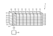
- FIG. 1 is a conceptual perspective view showing an example of the laminated light guide plate of the present invention.
- the laminated light guide plate 1 has a structure in which eight glass plates 10 are laminated and integrated with an adhesive (not shown). Each glass plate 10 has a half mirror portion 11 formed therein by laser light irradiation. Moreover, the incident member 13 is arrange
- the light emitted from the light source 15 enters the incident member 13, is reflected by the reflection mirror unit 14, and propagates from the end surface 12 of each glass plate 10 to the inside of each glass plate 10. Go.
- the light propagated inside the glass plate 10 is reflected by the half mirror unit 11 and emitted to the outside of the light guide plate 1. Thereby, a high-resolution 3D image can be realized.
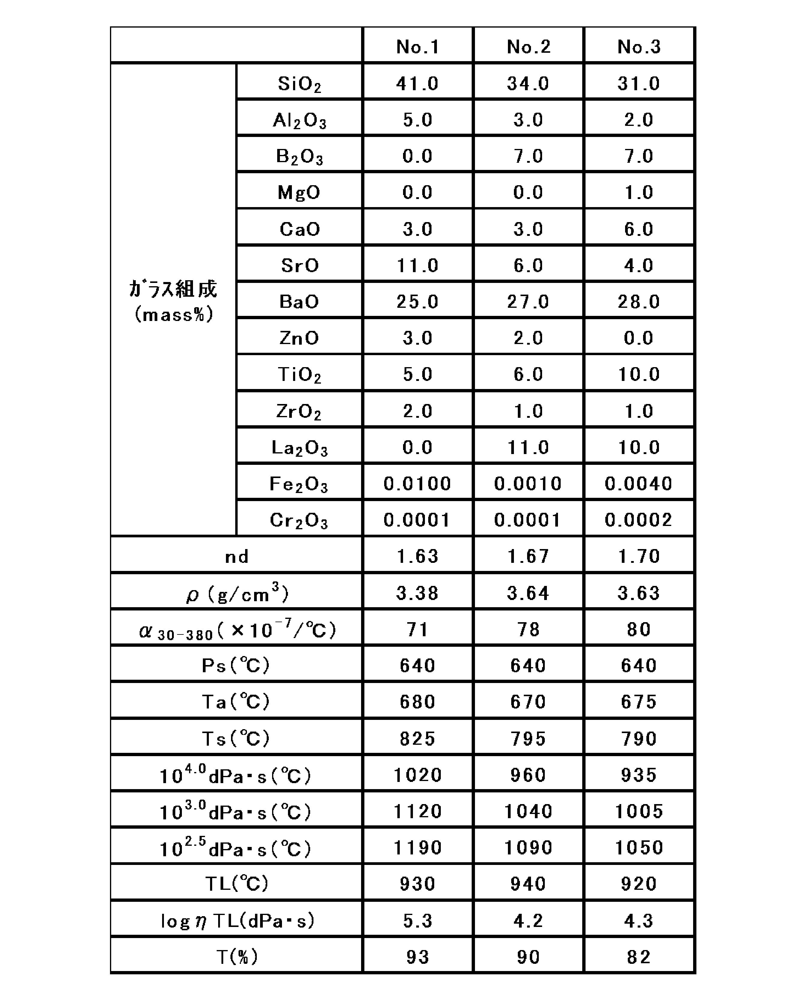
- Table 1 shows sample No. 1 to 3 are shown.
- Each sample in the table was prepared as follows. First, glass raw materials were prepared so as to have the glass composition in the table, and were melted at 1600 ° C. for 24 hours using a platinum pot. Next, the obtained molten glass was poured onto a carbon plate and formed into a flat plate shape. About the obtained glass, the characteristic in a table
- the refractive index nd is such that the temperature range from (annealing point Ta + 30 ° C.) to (strain point Ps ⁇ 50 ° C.) becomes 0.1 ° C./min after preparing a rectangular solid sample of 25 mm ⁇ 25 mm ⁇ about 3 mm. This is a value measured by using a refractive index measuring instrument KPR-2000 manufactured by Shimadzu Corporation while annealing with a cooling rate and subsequently infiltrating an immersion liquid having a matching refractive index between the glasses.
- the density ⁇ is a value measured by the well-known Archimedes method.
- the thermal expansion coefficient ⁇ is a value measured with a dilatometer, and is an average value in a temperature range of 30 to 380 ° C.
- strain point Ps and the annealing point Ta are values measured based on the method of ASTM C336.
- the softening point Ts is a value measured based on the method of ASTM C338.
- the temperatures at high temperature viscosities of 10 4.0 dPa ⁇ s, 10 3.0 dPa ⁇ s, 10 2.5 dPa ⁇ s, and 10 2.0 dPa ⁇ s are values measured by the platinum ball pulling method.
- the transmittance T is an internal transmittance at an optical path length of 10 mm and a wavelength of 550 nm, and is transmitted through an optical path length of 10 mm by performing plate thickness conversion from measurement data obtained using an integrating sphere of a spectrophotometer UH4150 manufactured by Hitachi High-Tech Science. The rate is calculated.
- the liquid phase temperature TL passes through a standard sieve 30 mesh (500 ⁇ m), and the glass powder remaining in 50 mesh (300 ⁇ m) is placed in a platinum boat and held in a temperature gradient furnace for 24 hours to measure the temperature at which crystals precipitate. It is the value.
- the liquid phase viscosity log ⁇ TL is a value obtained by measuring the viscosity of the glass at the liquid phase temperature by a platinum ball pulling method.
- sample No. in Table 1 The material 1 was melted in a continuous melting furnace and formed into a plate shape having a plate thickness of 0.3 mm by an overflow down draw method to obtain a glass plate.
- the obtained glass plate was cut into a size of 300 mm ⁇ 300 mm by a laser and washed.
- the arithmetic surface roughness Ra of the end face of the glass plate after cutting was 0.5 nm.
- arithmetic surface roughness Ra of both surfaces of the glass plate was 0.2 nm.
- a dot-shaped Al film was formed as a reflection mirror on one surface of the glass plate by sputtering.
Landscapes
- Physics & Mathematics (AREA)
- General Physics & Mathematics (AREA)
- Optics & Photonics (AREA)
- Chemical & Material Sciences (AREA)
- Engineering & Computer Science (AREA)
- Chemical Kinetics & Catalysis (AREA)
- Life Sciences & Earth Sciences (AREA)
- General Chemical & Material Sciences (AREA)
- Geochemistry & Mineralogy (AREA)
- Materials Engineering (AREA)
- Organic Chemistry (AREA)
- Manufacturing & Machinery (AREA)
- Glass Compositions (AREA)
- Liquid Crystal (AREA)
Abstract
Description
10 ガラス板
11 ハーフミラー部
12 ガラス板の端面
13 入射部材
14 反射ミラー部
15 光源
Claims (14)
- ガラス板を備える導光板であって、
ガラス板の屈折率ndが1.56以上であり、且つガラス板の板厚が1.0mm以下であることを特徴とする導光板。 - ガラス板の端面の算術表面粗さRaが1μm以下であることを特徴とする請求項1に記載の導光板。
- ガラス板の両表面と端面とがなす交差角度がそれぞれ90°±3°以内であることを特徴とする請求項1又は2に記載の導光板。
- ガラス板の光路長10mm、波長550nmにおける内部透過率が80%以上であることを特徴とする請求項1~3の何れかに記載の導光板。
- ガラス板が、ガラス組成として、質量%で、SiO2 10~60%、Al2O3 0~8%、BaO 10~40%、TiO2+La2O3 3~30%を含有し、且つ液相粘度が104.0dPa・s以上であることを特徴とする請求項1~4の何れかに記載の導光板。
- ガラス板中のFe2O3の含有量が0.05質量%以下であることを特徴とする請求項1~5の何れかに記載の導光板。
- ガラス板中のCr2O3の含有量が0.0005質量%以下であることを特徴とする請求項1~6の何れかに記載の導光板。
- ガラス板のうねりが0.1μm以下であることを特徴とする請求項1~7の何れかに記載の導光板。
- ガラス板の少なくとも一つの表面の算術表面粗さRaが0.5nm未満であることを特徴とする請求項1~8の何れかに記載の導光板。
- ガラス板の少なくとも一つの表面の鉛筆硬度が3H以上であることを特徴とする請求項1~9の何れかに記載の導光板。
- ガラス板が曲面を有し、その曲率半径が200mm以上であることを特徴とする請求項1~10の何れかに記載の導光板。
- ガラス板の端面から30mm以内の位置に映像信号を入射させるための入射部材を更に備えることを特徴とする請求項1~11の何れかに記載の導光板。
- ヘッドマウントディスプレイ用部材に用いることを特徴とする請求項1~12の何れかに記載の導光板。
- 導光板を複数枚積層させた積層導光板であって、
導光板が、請求項1~13の何れかに記載の導光板であることを特徴とする積層導光板。
Priority Applications (5)
| Application Number | Priority Date | Filing Date | Title |
|---|---|---|---|
| KR1020237020549A KR20230093371A (ko) | 2015-07-30 | 2016-07-25 | 도광판 및 이것을 사용한 적층 도광판 |
| EP16830480.6A EP3330754B1 (en) | 2015-07-30 | 2016-07-25 | Light guiding panel and laminated light guiding panel using same |
| CN201680044372.1A CN107850725B (zh) | 2015-07-30 | 2016-07-25 | 导光板和使用了其的层叠导光板 |
| KR1020187005727A KR102547043B1 (ko) | 2015-07-30 | 2016-07-25 | 도광판 및 이것을 사용한 적층 도광판 |
| US15/748,271 US20180217317A1 (en) | 2015-07-30 | 2016-07-25 | Light guiding panel and laminated light guiding panel using same |
Applications Claiming Priority (2)
| Application Number | Priority Date | Filing Date | Title |
|---|---|---|---|
| JP2015150304A JP2017032673A (ja) | 2015-07-30 | 2015-07-30 | 導光板及びこれを用いた積層導光板 |
| JP2015-150304 | 2015-07-30 |
Publications (1)
| Publication Number | Publication Date |
|---|---|
| WO2017018375A1 true WO2017018375A1 (ja) | 2017-02-02 |
Family
ID=57884850
Family Applications (1)
| Application Number | Title | Priority Date | Filing Date |
|---|---|---|---|
| PCT/JP2016/071715 Ceased WO2017018375A1 (ja) | 2015-07-30 | 2016-07-25 | 導光板及びこれを用いた積層導光板 |
Country Status (6)
| Country | Link |
|---|---|
| US (1) | US20180217317A1 (ja) |
| EP (1) | EP3330754B1 (ja) |
| JP (1) | JP2017032673A (ja) |
| KR (2) | KR20230093371A (ja) |
| CN (1) | CN107850725B (ja) |
| WO (1) | WO2017018375A1 (ja) |
Cited By (9)
| Publication number | Priority date | Publication date | Assignee | Title |
|---|---|---|---|---|
| CN109254402A (zh) * | 2017-07-12 | 2019-01-22 | 豪雅冠得股份有限公司 | 导光板、图像显示装置 |
| WO2020004131A1 (ja) * | 2018-06-27 | 2020-01-02 | 日本電気硝子株式会社 | ガラス基板積層体の製造方法、ガラス基板、ガラス基板積層体及びヘッドマウントディスプレイ |
| WO2020004141A1 (ja) * | 2018-06-26 | 2020-01-02 | 日本電気硝子株式会社 | ガラス板 |
| WO2020004140A1 (ja) * | 2018-06-26 | 2020-01-02 | 日本電気硝子株式会社 | ガラス板 |
| CN110869329A (zh) * | 2017-06-23 | 2020-03-06 | Agc株式会社 | 光学玻璃和光学部件 |
| US11815691B2 (en) | 2017-07-12 | 2023-11-14 | Hoya Corporation | Light guide plate made of lead-free glass having a high refractive index and image display device using a light guide plate |
| EP4368340A1 (en) * | 2017-12-27 | 2024-05-15 | Hoya Corporation | Disk-shaped glass substrate manufacturing method, sheet glass substrate manufacturing method, light guide plate manufacturing method, and disk-shaped glass substrate |
| WO2024257610A1 (ja) * | 2023-06-16 | 2024-12-19 | Agc株式会社 | ガラス及びガラスの製造方法 |
| JP2025084947A (ja) * | 2020-04-21 | 2025-06-03 | Hoya株式会社 | 円盤状ガラス基板 |
Families Citing this family (8)
| Publication number | Priority date | Publication date | Assignee | Title |
|---|---|---|---|---|
| JP7392914B2 (ja) * | 2018-02-20 | 2023-12-06 | 日本電気硝子株式会社 | ガラス |
| WO2020090051A1 (ja) * | 2018-10-31 | 2020-05-07 | Agc株式会社 | 導光板用光学材料及び導光板 |
| JP7445186B2 (ja) * | 2018-12-07 | 2024-03-07 | 日本電気硝子株式会社 | ガラス |
| EP4053087A4 (en) | 2019-10-31 | 2023-12-06 | Nippon Electric Glass Co., Ltd. | OPTICAL GLASS PLATE |
| DE112021002188T5 (de) | 2020-04-06 | 2023-04-13 | Nippon Electric Glass Co., Ltd. | Optisches glas |
| DE112021003134T5 (de) | 2020-06-04 | 2023-03-30 | Nippon Electric Glass Co., Ltd. | Glasfolie |
| US20240351933A1 (en) | 2021-08-12 | 2024-10-24 | Nippon Electric Glass Co., Ltd. | Optical glass plate |
| JPWO2023120429A1 (ja) * | 2021-12-20 | 2023-06-29 |
Citations (12)
| Publication number | Priority date | Publication date | Assignee | Title |
|---|---|---|---|---|
| JP2003337298A (ja) * | 2002-05-17 | 2003-11-28 | Sony Corp | 画像表示装置 |
| WO2005093493A1 (ja) * | 2004-03-29 | 2005-10-06 | Sony Corporation | 光学装置及び虚像表示装置 |
| JP2006301611A (ja) * | 2005-03-25 | 2006-11-02 | Fujinon Corp | 導光板および導光板ユニット |
| JP2010243787A (ja) * | 2009-04-06 | 2010-10-28 | Hoya Corp | 映像表示装置、およびヘッドマウントディスプレイ |
| JP2011039490A (ja) * | 2009-07-17 | 2011-02-24 | Sony Corp | 画像表示装置、頭部装着型ディスプレイ及び光ビーム伸長装置 |
| JP2013063892A (ja) * | 2011-09-02 | 2013-04-11 | Nippon Electric Glass Co Ltd | 高屈折率ガラス |
| WO2013140792A1 (ja) * | 2012-03-21 | 2013-09-26 | オリンパス株式会社 | 光学素子 |
| JP2013237604A (ja) * | 2012-04-17 | 2013-11-28 | Avanstrate Inc | ディスプレイ用ガラス基板の製造方法、ガラス基板及びディスプレイ用パネル |
| US20140293434A1 (en) * | 2011-12-06 | 2014-10-02 | Beijing Institute Of Technology | Display apparatus and system and display method thereof |
| JP2014189457A (ja) * | 2013-03-27 | 2014-10-06 | Avanstrate Inc | ガラス板製造方法、および、ガラス板製造装置 |
| JP2015049278A (ja) * | 2013-08-30 | 2015-03-16 | セイコーエプソン株式会社 | 光学デバイス及び画像表示装置 |
| JP2015072896A (ja) * | 2013-09-03 | 2015-04-16 | 日本電気硝子株式会社 | 導光板 |
Family Cites Families (19)
| Publication number | Priority date | Publication date | Assignee | Title |
|---|---|---|---|---|
| JP2001048571A (ja) * | 1999-06-04 | 2001-02-20 | Sumitomo Metal Ind Ltd | 短波長光の透過性に優れた石英ガラスとその製造方法 |
| GB0108838D0 (en) * | 2001-04-07 | 2001-05-30 | Cambridge 3D Display Ltd | Far field display |
| WO2006104160A1 (ja) * | 2005-03-29 | 2006-10-05 | Sharp Kabushiki Kaisha | 表示装置 |
| TWI316928B (en) * | 2005-04-28 | 2009-11-11 | Ohara Kk | Optical glass |
| JP4673676B2 (ja) * | 2005-06-10 | 2011-04-20 | シチズン電子株式会社 | バックライト装置 |
| US7989379B2 (en) * | 2005-06-29 | 2011-08-02 | Nippon Electric Glass Co., Ltd. | Optical glass |
| CN101589326B (zh) * | 2006-12-28 | 2011-06-29 | 诺基亚公司 | 用于在二维上扩展出射光瞳的设备 |
| JP5302611B2 (ja) * | 2008-02-08 | 2013-10-02 | 株式会社オハラ | 光学部品用ガラス部材及びそれに用いるガラス組成物 |
| US8157388B2 (en) * | 2008-03-31 | 2012-04-17 | Texas Instruments Incorporated | System and method for a projection display system using an optical lightguide |
| US20110190749A1 (en) * | 2008-11-24 | 2011-08-04 | Mcmillan Kathleen | Low Profile Apparatus and Method for Phototherapy |
| JP5203244B2 (ja) * | 2009-02-04 | 2013-06-05 | 富士フイルム株式会社 | 導光板、面状照明装置および導光板の製造方法 |
| TWI527781B (zh) * | 2009-07-08 | 2016-04-01 | 日本電氣硝子股份有限公司 | 玻璃板 |
| CN102044272B (zh) * | 2009-09-30 | 2014-12-17 | Hoya株式会社 | 光学信息记录/再现光学系统和光学信息记录/再现装置 |
| CN102667540A (zh) * | 2009-12-15 | 2012-09-12 | 夏普株式会社 | 光学叠层体、照明装置、液晶显示装置和光学叠层体的制造方法 |
| KR101638488B1 (ko) * | 2010-12-08 | 2016-07-11 | 니폰 덴키 가라스 가부시키가이샤 | 고굴절률 유리 |
| US8999871B2 (en) * | 2011-05-25 | 2015-04-07 | Nippon Electric Glass Co., Ltd. | High refractive index glass |
| WO2013188464A1 (en) * | 2012-06-11 | 2013-12-19 | Magic Leap, Inc. | Multiple depth plane three-dimensional display using a wave guide reflector array projector |
| CN105264284B (zh) * | 2013-09-03 | 2018-04-06 | 日本电气硝子株式会社 | 导光板 |
| CN104699309B (zh) * | 2015-03-31 | 2017-06-13 | 合肥京东方光电科技有限公司 | 一种触摸屏、其制作方法及显示装置 |
-
2015
- 2015-07-30 JP JP2015150304A patent/JP2017032673A/ja active Pending
-
2016
- 2016-07-25 KR KR1020237020549A patent/KR20230093371A/ko not_active Ceased
- 2016-07-25 CN CN201680044372.1A patent/CN107850725B/zh active Active
- 2016-07-25 KR KR1020187005727A patent/KR102547043B1/ko active Active
- 2016-07-25 WO PCT/JP2016/071715 patent/WO2017018375A1/ja not_active Ceased
- 2016-07-25 EP EP16830480.6A patent/EP3330754B1/en active Active
- 2016-07-25 US US15/748,271 patent/US20180217317A1/en not_active Abandoned
Patent Citations (12)
| Publication number | Priority date | Publication date | Assignee | Title |
|---|---|---|---|---|
| JP2003337298A (ja) * | 2002-05-17 | 2003-11-28 | Sony Corp | 画像表示装置 |
| WO2005093493A1 (ja) * | 2004-03-29 | 2005-10-06 | Sony Corporation | 光学装置及び虚像表示装置 |
| JP2006301611A (ja) * | 2005-03-25 | 2006-11-02 | Fujinon Corp | 導光板および導光板ユニット |
| JP2010243787A (ja) * | 2009-04-06 | 2010-10-28 | Hoya Corp | 映像表示装置、およびヘッドマウントディスプレイ |
| JP2011039490A (ja) * | 2009-07-17 | 2011-02-24 | Sony Corp | 画像表示装置、頭部装着型ディスプレイ及び光ビーム伸長装置 |
| JP2013063892A (ja) * | 2011-09-02 | 2013-04-11 | Nippon Electric Glass Co Ltd | 高屈折率ガラス |
| US20140293434A1 (en) * | 2011-12-06 | 2014-10-02 | Beijing Institute Of Technology | Display apparatus and system and display method thereof |
| WO2013140792A1 (ja) * | 2012-03-21 | 2013-09-26 | オリンパス株式会社 | 光学素子 |
| JP2013237604A (ja) * | 2012-04-17 | 2013-11-28 | Avanstrate Inc | ディスプレイ用ガラス基板の製造方法、ガラス基板及びディスプレイ用パネル |
| JP2014189457A (ja) * | 2013-03-27 | 2014-10-06 | Avanstrate Inc | ガラス板製造方法、および、ガラス板製造装置 |
| JP2015049278A (ja) * | 2013-08-30 | 2015-03-16 | セイコーエプソン株式会社 | 光学デバイス及び画像表示装置 |
| JP2015072896A (ja) * | 2013-09-03 | 2015-04-16 | 日本電気硝子株式会社 | 導光板 |
Non-Patent Citations (1)
| Title |
|---|
| See also references of EP3330754A4 * |
Cited By (22)
| Publication number | Priority date | Publication date | Assignee | Title |
|---|---|---|---|---|
| CN110869329A (zh) * | 2017-06-23 | 2020-03-06 | Agc株式会社 | 光学玻璃和光学部件 |
| US11543658B2 (en) | 2017-07-12 | 2023-01-03 | Hoya Corporation | Light guide plate made of lead-free glass having a high refractive index and image display device using a light guide plate |
| US11815691B2 (en) | 2017-07-12 | 2023-11-14 | Hoya Corporation | Light guide plate made of lead-free glass having a high refractive index and image display device using a light guide plate |
| EP3428710B1 (en) * | 2017-07-12 | 2023-09-13 | HOYA Corporation | Light guide plate and image display device |
| CN109254402A (zh) * | 2017-07-12 | 2019-01-22 | 豪雅冠得股份有限公司 | 导光板、图像显示装置 |
| EP4368340A1 (en) * | 2017-12-27 | 2024-05-15 | Hoya Corporation | Disk-shaped glass substrate manufacturing method, sheet glass substrate manufacturing method, light guide plate manufacturing method, and disk-shaped glass substrate |
| JPWO2020004140A1 (ja) * | 2018-06-26 | 2021-08-02 | 日本電気硝子株式会社 | ガラス板 |
| JP7389409B2 (ja) | 2018-06-26 | 2023-11-30 | 日本電気硝子株式会社 | ガラス板 |
| US20210253470A1 (en) * | 2018-06-26 | 2021-08-19 | Nippon Electric Glass Co., Ltd. | Plate glass |
| JPWO2020004141A1 (ja) * | 2018-06-26 | 2021-08-02 | 日本電気硝子株式会社 | ガラス板 |
| US11932572B2 (en) | 2018-06-26 | 2024-03-19 | Nippon Electric Glass Co., Ltd. | Plate glass |
| US11629089B2 (en) | 2018-06-26 | 2023-04-18 | Nippon Electric Glass Co., Ltd. | Plate glass |
| JP7339607B2 (ja) | 2018-06-26 | 2023-09-06 | 日本電気硝子株式会社 | ガラス板 |
| WO2020004140A1 (ja) * | 2018-06-26 | 2020-01-02 | 日本電気硝子株式会社 | ガラス板 |
| JP2023133333A (ja) * | 2018-06-26 | 2023-09-22 | 日本電気硝子株式会社 | ガラス板 |
| WO2020004141A1 (ja) * | 2018-06-26 | 2020-01-02 | 日本電気硝子株式会社 | ガラス板 |
| JP2023175779A (ja) * | 2018-06-26 | 2023-12-12 | 日本電気硝子株式会社 | ガラス板 |
| JPWO2020004131A1 (ja) * | 2018-06-27 | 2021-08-05 | 日本電気硝子株式会社 | ガラス基板積層体の製造方法、ガラス基板、ガラス基板積層体及びヘッドマウントディスプレイ |
| JP7228135B2 (ja) | 2018-06-27 | 2023-02-24 | 日本電気硝子株式会社 | ガラス基板積層体の製造方法、ガラス基板、ガラス基板積層体及びヘッドマウントディスプレイ |
| WO2020004131A1 (ja) * | 2018-06-27 | 2020-01-02 | 日本電気硝子株式会社 | ガラス基板積層体の製造方法、ガラス基板、ガラス基板積層体及びヘッドマウントディスプレイ |
| JP2025084947A (ja) * | 2020-04-21 | 2025-06-03 | Hoya株式会社 | 円盤状ガラス基板 |
| WO2024257610A1 (ja) * | 2023-06-16 | 2024-12-19 | Agc株式会社 | ガラス及びガラスの製造方法 |
Also Published As
| Publication number | Publication date |
|---|---|
| JP2017032673A (ja) | 2017-02-09 |
| EP3330754A4 (en) | 2019-03-27 |
| EP3330754B1 (en) | 2020-09-09 |
| US20180217317A1 (en) | 2018-08-02 |
| KR102547043B1 (ko) | 2023-06-23 |
| EP3330754A1 (en) | 2018-06-06 |
| KR20180033577A (ko) | 2018-04-03 |
| CN107850725A (zh) | 2018-03-27 |
| KR20230093371A (ko) | 2023-06-27 |
| CN107850725B (zh) | 2021-05-14 |
Similar Documents
| Publication | Publication Date | Title |
|---|---|---|
| WO2017018375A1 (ja) | 導光板及びこれを用いた積層導光板 | |
| JP7772130B2 (ja) | 導光板用ガラス板 | |
| JP7222360B2 (ja) | 反射防止膜付ガラス基板及び光学部品 | |
| JP5835654B2 (ja) | 強化ガラス基板の製造方法 | |
| JP5582462B2 (ja) | ガラス板 | |
| JP2024020435A (ja) | ガラス | |
| US20130219966A1 (en) | Method of manufacturing chemically strengthened glass plate | |
| JP2012036074A (ja) | ガラス板 | |
| JP7652211B2 (ja) | カバーガラス | |
| JP2023175779A (ja) | ガラス板 | |
| KR101498938B1 (ko) | 복합 기판 | |
| US20240182351A1 (en) | Plate glass | |
| JP2014032740A (ja) | 複合基板 | |
| JP7228135B2 (ja) | ガラス基板積層体の製造方法、ガラス基板、ガラス基板積層体及びヘッドマウントディスプレイ | |
| JP2021001104A (ja) | ガラス | |
| JP2014019627A (ja) | 強化ガラス及び表示デバイス | |
| JP2023181103A (ja) | ガラス | |
| JP6066382B2 (ja) | 強化フロートガラス基板及びその製造方法 |
Legal Events
| Date | Code | Title | Description |
|---|---|---|---|
| 121 | Ep: the epo has been informed by wipo that ep was designated in this application |
Ref document number: 16830480 Country of ref document: EP Kind code of ref document: A1 |
|
| WWE | Wipo information: entry into national phase |
Ref document number: 15748271 Country of ref document: US |
|
| NENP | Non-entry into the national phase |
Ref country code: DE |
|
| ENP | Entry into the national phase |
Ref document number: 20187005727 Country of ref document: KR Kind code of ref document: A |
|
| WWE | Wipo information: entry into national phase |
Ref document number: 2016830480 Country of ref document: EP |