WO2017018447A1 - 採光フィルム、採光フィルム形成用金型、採光フィルムの製造方法 - Google Patents
採光フィルム、採光フィルム形成用金型、採光フィルムの製造方法 Download PDFInfo
- Publication number
- WO2017018447A1 WO2017018447A1 PCT/JP2016/072012 JP2016072012W WO2017018447A1 WO 2017018447 A1 WO2017018447 A1 WO 2017018447A1 JP 2016072012 W JP2016072012 W JP 2016072012W WO 2017018447 A1 WO2017018447 A1 WO 2017018447A1
- Authority
- WO
- WIPO (PCT)
- Prior art keywords
- protrusion
- recess
- light
- daylighting
- daylighting film
- Prior art date
- Legal status (The legal status is an assumption and is not a legal conclusion. Google has not performed a legal analysis and makes no representation as to the accuracy of the status listed.)
- Ceased
Links
Images


Classifications
-
- B—PERFORMING OPERATIONS; TRANSPORTING
- B29—WORKING OF PLASTICS; WORKING OF SUBSTANCES IN A PLASTIC STATE IN GENERAL
- B29C—SHAPING OR JOINING OF PLASTICS; SHAPING OF MATERIAL IN A PLASTIC STATE, NOT OTHERWISE PROVIDED FOR; AFTER-TREATMENT OF THE SHAPED PRODUCTS, e.g. REPAIRING
- B29C39/00—Shaping by casting, i.e. introducing the moulding material into a mould or between confining surfaces without significant moulding pressure; Apparatus therefor
- B29C39/14—Shaping by casting, i.e. introducing the moulding material into a mould or between confining surfaces without significant moulding pressure; Apparatus therefor for making articles of indefinite length
- B29C39/148—Shaping by casting, i.e. introducing the moulding material into a mould or between confining surfaces without significant moulding pressure; Apparatus therefor for making articles of indefinite length characterised by the shape of the surface
-
- F—MECHANICAL ENGINEERING; LIGHTING; HEATING; WEAPONS; BLASTING
- F21—LIGHTING
- F21S—NON-PORTABLE LIGHTING DEVICES; SYSTEMS THEREOF; VEHICLE LIGHTING DEVICES SPECIALLY ADAPTED FOR VEHICLE EXTERIORS
- F21S11/00—Non-electric lighting devices or systems using daylight
- F21S11/007—Non-electric lighting devices or systems using daylight characterised by the means for transmitting light into the interior of a building
-
- B—PERFORMING OPERATIONS; TRANSPORTING
- B29—WORKING OF PLASTICS; WORKING OF SUBSTANCES IN A PLASTIC STATE IN GENERAL
- B29C—SHAPING OR JOINING OF PLASTICS; SHAPING OF MATERIAL IN A PLASTIC STATE, NOT OTHERWISE PROVIDED FOR; AFTER-TREATMENT OF THE SHAPED PRODUCTS, e.g. REPAIRING
- B29C39/00—Shaping by casting, i.e. introducing the moulding material into a mould or between confining surfaces without significant moulding pressure; Apparatus therefor
- B29C39/14—Shaping by casting, i.e. introducing the moulding material into a mould or between confining surfaces without significant moulding pressure; Apparatus therefor for making articles of indefinite length
- B29C39/142—Shaping by casting, i.e. introducing the moulding material into a mould or between confining surfaces without significant moulding pressure; Apparatus therefor for making articles of indefinite length by casting in serveral steps
- B29C39/146—Shaping by casting, i.e. introducing the moulding material into a mould or between confining surfaces without significant moulding pressure; Apparatus therefor for making articles of indefinite length by casting in serveral steps for making multilayered articles
-
- B—PERFORMING OPERATIONS; TRANSPORTING
- B29—WORKING OF PLASTICS; WORKING OF SUBSTANCES IN A PLASTIC STATE IN GENERAL
- B29C—SHAPING OR JOINING OF PLASTICS; SHAPING OF MATERIAL IN A PLASTIC STATE, NOT OTHERWISE PROVIDED FOR; AFTER-TREATMENT OF THE SHAPED PRODUCTS, e.g. REPAIRING
- B29C41/00—Shaping by coating a mould, core or other substrate, i.e. by depositing material and stripping-off the shaped article; Apparatus therefor
- B29C41/02—Shaping by coating a mould, core or other substrate, i.e. by depositing material and stripping-off the shaped article; Apparatus therefor for making articles of definite length, i.e. discrete articles
-
- B—PERFORMING OPERATIONS; TRANSPORTING
- B29—WORKING OF PLASTICS; WORKING OF SUBSTANCES IN A PLASTIC STATE IN GENERAL
- B29C—SHAPING OR JOINING OF PLASTICS; SHAPING OF MATERIAL IN A PLASTIC STATE, NOT OTHERWISE PROVIDED FOR; AFTER-TREATMENT OF THE SHAPED PRODUCTS, e.g. REPAIRING
- B29C41/00—Shaping by coating a mould, core or other substrate, i.e. by depositing material and stripping-off the shaped article; Apparatus therefor
- B29C41/34—Component parts, details or accessories; Auxiliary operations
- B29C41/38—Moulds, cores or other substrates
-
- E—FIXED CONSTRUCTIONS
- E06—DOORS, WINDOWS, SHUTTERS, OR ROLLER BLINDS IN GENERAL; LADDERS
- E06B—FIXED OR MOVABLE CLOSURES FOR OPENINGS IN BUILDINGS, VEHICLES, FENCES OR LIKE ENCLOSURES IN GENERAL, e.g. DOORS, WINDOWS, BLINDS, GATES
- E06B3/00—Window sashes, door leaves, or like elements for closing wall or like openings; Layout of fixed or moving closures, e.g. windows in wall or like openings; Features of rigidly-mounted outer frames relating to the mounting of wing frames
- E06B3/66—Units comprising two or more parallel glass or like panes permanently secured together
-
- E—FIXED CONSTRUCTIONS
- E06—DOORS, WINDOWS, SHUTTERS, OR ROLLER BLINDS IN GENERAL; LADDERS
- E06B—FIXED OR MOVABLE CLOSURES FOR OPENINGS IN BUILDINGS, VEHICLES, FENCES OR LIKE ENCLOSURES IN GENERAL, e.g. DOORS, WINDOWS, BLINDS, GATES
- E06B5/00—Doors, windows, or like closures for special purposes; Border constructions therefor
-
- F—MECHANICAL ENGINEERING; LIGHTING; HEATING; WEAPONS; BLASTING
- F21—LIGHTING
- F21S—NON-PORTABLE LIGHTING DEVICES; SYSTEMS THEREOF; VEHICLE LIGHTING DEVICES SPECIALLY ADAPTED FOR VEHICLE EXTERIORS
- F21S11/00—Non-electric lighting devices or systems using daylight
-
- F—MECHANICAL ENGINEERING; LIGHTING; HEATING; WEAPONS; BLASTING
- F21—LIGHTING
- F21V—FUNCTIONAL FEATURES OR DETAILS OF LIGHTING DEVICES OR SYSTEMS THEREOF; STRUCTURAL COMBINATIONS OF LIGHTING DEVICES WITH OTHER ARTICLES, NOT OTHERWISE PROVIDED FOR
- F21V5/00—Refractors for light sources
- F21V5/002—Refractors for light sources using microoptical elements for redirecting or diffusing light
- F21V5/005—Refractors for light sources using microoptical elements for redirecting or diffusing light using microprisms
-
- G—PHYSICS
- G02—OPTICS
- G02B—OPTICAL ELEMENTS, SYSTEMS OR APPARATUS
- G02B5/00—Optical elements other than lenses
-
- G—PHYSICS
- G02—OPTICS
- G02B—OPTICAL ELEMENTS, SYSTEMS OR APPARATUS
- G02B5/00—Optical elements other than lenses
- G02B5/02—Diffusing elements; Afocal elements
- G02B5/0205—Diffusing elements; Afocal elements characterised by the diffusing properties
- G02B5/021—Diffusing elements; Afocal elements characterised by the diffusing properties the diffusion taking place at the element's surface, e.g. by means of surface roughening or microprismatic structures
- G02B5/0231—Diffusing elements; Afocal elements characterised by the diffusing properties the diffusion taking place at the element's surface, e.g. by means of surface roughening or microprismatic structures the surface having microprismatic or micropyramidal shape
-
- B—PERFORMING OPERATIONS; TRANSPORTING
- B29—WORKING OF PLASTICS; WORKING OF SUBSTANCES IN A PLASTIC STATE IN GENERAL
- B29K—INDEXING SCHEME ASSOCIATED WITH SUBCLASSES B29B, B29C OR B29D, RELATING TO MOULDING MATERIALS OR TO MATERIALS FOR MOULDS, REINFORCEMENTS, FILLERS OR PREFORMED PARTS, e.g. INSERTS
- B29K2101/00—Use of unspecified macromolecular compounds as moulding material
- B29K2101/10—Thermosetting resins
-
- B—PERFORMING OPERATIONS; TRANSPORTING
- B29—WORKING OF PLASTICS; WORKING OF SUBSTANCES IN A PLASTIC STATE IN GENERAL
- B29K—INDEXING SCHEME ASSOCIATED WITH SUBCLASSES B29B, B29C OR B29D, RELATING TO MOULDING MATERIALS OR TO MATERIALS FOR MOULDS, REINFORCEMENTS, FILLERS OR PREFORMED PARTS, e.g. INSERTS
- B29K2101/00—Use of unspecified macromolecular compounds as moulding material
- B29K2101/12—Thermoplastic materials
-
- B—PERFORMING OPERATIONS; TRANSPORTING
- B29—WORKING OF PLASTICS; WORKING OF SUBSTANCES IN A PLASTIC STATE IN GENERAL
- B29K—INDEXING SCHEME ASSOCIATED WITH SUBCLASSES B29B, B29C OR B29D, RELATING TO MOULDING MATERIALS OR TO MATERIALS FOR MOULDS, REINFORCEMENTS, FILLERS OR PREFORMED PARTS, e.g. INSERTS
- B29K2995/00—Properties of moulding materials, reinforcements, fillers, preformed parts or moulds
- B29K2995/0018—Properties of moulding materials, reinforcements, fillers, preformed parts or moulds having particular optical properties, e.g. fluorescent or phosphorescent
- B29K2995/0031—Refractive
-
- B—PERFORMING OPERATIONS; TRANSPORTING
- B29—WORKING OF PLASTICS; WORKING OF SUBSTANCES IN A PLASTIC STATE IN GENERAL
- B29L—INDEXING SCHEME ASSOCIATED WITH SUBCLASS B29C, RELATING TO PARTICULAR ARTICLES
- B29L2011/00—Optical elements, e.g. lenses, prisms
Definitions
- Some embodiments of the present invention relate to a daylighting film, a daylighting film forming mold, and a method for manufacturing the daylighting film.
- Patent Document 1 A technique described in Patent Document 1 is known as a technique for efficiently guiding light incident on a window glass indoors.
- a daylighting film in which a plurality of unit prisms are formed on one surface of a translucent support is attached to the inner surface (inner side surface) of the window glass with the unit prism side facing outward. Is.
- the light incident from the unit prism side is refracted on the surface of the unit prism, passes through the unit prism, the support, and the window glass and enters the room indoors.
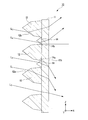
- the room 2003 is an office, and the cross section (XZ cross section) of the room 2003 is rectangular.
- the height H3 of the room 2003 (the height from the floor 2003c to the ceiling 2003a) is, for example, 2.7 m.
- the window 2002 is provided, for example, at a portion of 1.8 m from the ceiling 2003a on the wall 2003b side.
- the height H2 of the window 2002 is 1.8 m, for example.
- the daylighting film 2001 is provided on the inner surface of the window 2002 at a portion that does not block human vision (for example, a portion of 0.6 m from the ceiling 2003a).
- the height H1 of the daylighting film 2001 is 0.6 m, for example.
- the room model 2000 it is assumed that a person moves, for example, 1 m away from the wall 2003b. In the part D near the window, there is no person. The portion D near the window is 1 m, for example. Based on the portion D in the vicinity of the window, a region where a person moves is assumed.
- the position of the human eye is assumed to be, for example, 0.8 m to 1.8 m from the floor 2003c.
- the eye height Ha of the person 2005 standing on the floor 2003c is, for example, 1.8 m.
- the eye height Hb of the person 2004 sitting on the chair is, for example, 0.8 m. Based on the eye heights Ha and Hb, the range of the position of the human eye is assumed.
- the daylighting film 2001 has a function of advancing external light toward the ceiling 2003a.
- the light traveling toward the ceiling 2003a is reflected by the ceiling 2003a to illuminate the room, and serves as a substitute for illumination.
- the light that has passed through the daylighting film 2001 travels not only toward the ceiling 2003a but also toward the wall 2003d or the floor 2003c.
- the light that has passed through the daylighting film 2001 may be directed toward the position of the eyes of a person who is indoors. Such light makes a person who is indoors feel dazzling.
- a glare area AR is an area in which a person who is indoors feels dazzling.
- the range of the glare area AR is defined based on the area where the person moves and the position of the person's eyes.
- the glare area AR is an area of, for example, 0.8 m to 1.8 m from the floor 2003 c at a position 1 m away from the wall 2003 b, for example.
- FIG. 47 is an explanatory diagram of the incident angle and the emission angle.
- illustration of the base material of the lighting film 2001 is abbreviate
- the angle formed between the horizontal direction (X direction) and the light incident on the lighting film 2001 is defined as an incident angle ⁇ in
- the angle formed between the horizontal direction and the light emitted from the lighting film 2001 is defined as an emission angle ⁇ out.
- the emission angle ⁇ out is 0 ° in the normal direction passing through the center of the daylighting film 2001 (the center of the interface between the protrusion and the base)
- the ceiling 2003a is positive (+) than the horizontal direction
- the floor 2003c is higher than the horizontal direction.
- the side is a negative (-) angle. That is, the injection angle ⁇ out has a positive counterclockwise angle and a negative clockwise angle.
- the second protrusion 3013 has an inclined surface inclined with respect to the one surface 3010a of the base material 3010, and the height of the second protrusion 3013 is smaller than the height of the first protrusion 3011. Devised It has been.
- the second protrusion 3013 has a longitudinal direction in approximately one direction (Y direction), and the one direction is disposed in a direction substantially parallel to one side of the base material 3010 having a rectangular shape.
- the second protrusion 3013 is configured as a stripe-shaped protrusion extending in the Y direction.
- the shape of the cross section (XZ cross section) of the second protrusion 3013 is a triangle.
- the second protrusion 3013 has an inclined surface 3013 b that is inclined with respect to one surface 3010 a of the base material 3010.
- the width in the short direction (Z direction) of the second protrusion 3013 is w2
- the height in the normal direction (X direction) of the base material 3010 of the second protrusion 3013 is h2
- the width w2 of the protrusion 3013 is smaller than the interval s between the plurality of first protrusions 3011, and the height h2 of the second protrusion 3013 is smaller than the height h1 of the first protrusion 3011.
- a discontinuous region in which the second protrusion 3013 and the first protrusion 3011 are not continuous between the second protrusion 3013 and the first protrusion 3011 There is a non-formation region) 3010c in which the second protrusion 3013 and the first protrusion 3011 are not formed.
- the angle formed between the end surface 3013c of the second protrusion 3013 on the base material 3010 side and the side surface 3013a of the second protrusion 3013 is an angle ⁇ 1, and the end surface 3013c of the second protrusion 3013 on the base material 3010 side and the second surface 3013a.
- the angle formed by the side surface 3013b (inclined surface) of the protrusion 3013 is an angle ⁇ 2
- the angle ⁇ 1 of the second protrusion 3013 is larger than the angle ⁇ 2 of the second protrusion 3013.
- the angle ⁇ 1 is, for example, 70 ° to 100 °
- the angle ⁇ 2 is, for example, 10 ° to 30 °.
- the same material as that of the first protrusion 3011 can be used.
- the refractive index of the second protrusion 3013 is equal to or greater than the refractive index of the first protrusion 3011 and the base material 3010.
- the refractive index of the second protrusion 3013 is about 1.5.
- the light La is incident on the daylighting film 3000 at an angle of ⁇ in. Then, the light is refracted in the non-formation region 3010c, and is emitted from the other surface 3010b of the base material 3010 in the downward direction and ⁇ out in a negative range.
- the incident angle ⁇ in and the emission angle ⁇ out have the same absolute value. That is, the light La can be a light ray in an angular range that is a glare, and can be a factor that makes a person in the room feel dazzling.
- a second protrusion 3013 is provided between the first protrusions 3011 on one surface 3010a of the base material 3010.
- the light Lb is incident on the daylighting film 3000 at an angle of ⁇ in and refracted by the side surface 3013b of the second protrusion 3013, whereby the traveling direction is changed from the bottom to the top, and the other surface 3010b of the base material 3010 is obtained. From the top, ⁇ out is emitted in a positive range. The lighting effect is obtained by illuminating the ceiling.
- the light Lc is incident on the daylighting film 3000 at an angle of ⁇ in, and is refracted by the side surface 3013a of the second protrusion 3013, whereby the traveling direction is further changed downward, and the other surface of the substrate 3010
- the light is emitted from 3010b in a downward direction and ⁇ out is in a negative range.
- the emission angle ⁇ out has an absolute value larger than the incident angle ⁇ in, and reaches the floor position closer to the window surface than the angle range where glare occurs. Therefore, it does not make a person in the room feel dazzling.
- a molding method using a mold has been used as a method for forming the projections of the daylighting film.
- a protrusion is formed using a mold formed as shown in FIGS. 49A to 49C.
- a rectangular parallelepiped metal member 5010 is cut using a cutting tool 4010 or the like to form a recess 5020 corresponding to the protrusion. If the projections are densely arranged, the daylighting efficiency of the daylighting film is increased. Therefore, as shown in FIG. 49B, also in the metal member 5010, a plurality of recesses 5020 are formed densely to obtain a mold 5000.
- a resin 6010 made of a photocurable resin or a thermosetting resin is applied to one surface 5010a of the metal member 5010 of the mold 5000. After filling the plurality of recesses 5020 with the resin 6010 and curing the resin 6010, the cured resin 6010 is peeled from the mold 5000 to obtain the daylighting film 6000 on which the plurality of protrusions 6020 are formed.
- a portion 5030 serving as a boundary between the adjacent concave portions 5020 and the concave portions 5020 in the metal member 5010 becomes very thin. Therefore, the part 5030 is easily deformed by a small force. Therefore, when the cured resin 6010 is peeled from the mold 5000, the portion 5030 is deformed by the stress generated by the peeling force, and as a result, the peeled resin 6010, particularly the protrusion 6020 is deformed.
- the protruding portion 6020 If the protruding portion 6020 is deformed and is not formed in a predetermined shape, the shape of the protruding portion 6020 cannot be controlled, and not only the lighting effect by the protruding portion 6020 is obtained, but also the number of rays passing through the glare region increases. Can happen. Therefore, the daylighting film in which the second projection that refracts in the direction where the angle of the outgoing light ray does not fall within the glare range is arranged at a position where the interval between the projections 6020 is maintained to some extent is from the viewpoint of both the lighting effect and glare. preferable.
- the provision of the second protrusion has a problem that not only the manufacturing process becomes complicated, but also the material cost and the manufacturing cost increase.
- the shape of the second protrusion there is a problem that it is not effective for the characteristics of the daylighting film.
- Some aspects of the present invention have been made in order to solve the above-described problems, and are a daylighting film capable of suppressing a person who is indoors from feeling dazzling, and the formation of the daylighting film. It aims at providing the manufacturing method of the daylighting film which used the metal mold
- the daylighting film of one aspect of the present invention includes a light-transmitting base material, a plurality of light-transmitting first protrusions provided adjacent to each other on one surface of the base material, and the first A gap provided between the protrusions of each other, and on one surface of the substrate, at least one of the gaps is provided adjacent to the first protrusion, and the first protrusion And at least one second protrusion made of the same material, and the height of the second protrusion based on one surface of the base is that of the base of the first protrusion It is lower than the height based on one side.
- the first protrusion and the second protrusion are inclined in different directions with respect to one surface of the base material, and at least a pair of opposed inclined surfaces is provided.
- One of the pair of inclined surfaces of the first protrusion and the one of the pair of inclined surfaces of the second protrusion have the same inclination with respect to one surface of the base material, or the first protrusion
- the other of the pair of inclined surfaces of the one protrusion and the other of the pair of inclined surfaces of the second protrusion have the same inclination with respect to the one surface of the substrate.
- the first protrusion and the second protrusion are similar in shape of at least the portion having the pair of inclined surfaces.
- the lighting film forming mold of one aspect of the present invention includes a main body portion made of metal, a plurality of first concave portions provided adjacent to each other on one surface side of the main body portion, and the first concave portions. And at least one second recess provided adjacent to the first recess at a depth between the first recess and the depth with respect to one surface of the main body of the second recess Is shallower than a depth based on one surface of the main body of the first recess.
- the first recess and the second recess are inclined in different directions with respect to one surface of the main body and opposed to each other.
- One of the pair of inner side surfaces of the first recess and the one of the pair of inner side surfaces of the second recess have the same inclination with respect to one surface of the main body, or the first It is preferable that the other of the pair of inner side surfaces of the one recess and the other of the pair of inner side surfaces of the second recess have the same inclination with respect to the one surface of the main body.
- the first recess and the second recess are similar in shape of at least the portion having the pair of inner side surfaces.
- the manufacturing method of the daylighting film of 1 aspect of this invention is a manufacturing method of the daylighting film using the metal mold for daylighting film formation of 1 aspect of this invention, Comprising: On one surface of the said main-body part, a light-transmitting property is provided. Applying a resin and filling the resin into the first and second recesses, and curing the resin to form a first protrusion and a second protrusion made of the resin. A step of forming the daylighting film, and a step of peeling the daylighting film from the daylighting film forming mold.
- a daylighting film capable of suppressing the dazzling feeling of an indoor person, a daylighting film forming mold used for forming the daylighting film, and the daylighting film A method for producing a daylighting film using a forming mold can be provided.
- FIG. 40 is a cross-sectional view of the roll screen shown in FIG. 39 taken along the line A-A ′.
- FIG. 46 is a diagram illustrating a room model including a daylighting film and an illumination dimming system, and is a cross-sectional view taken along line J-J ′ of FIG. 45. It is a top view which shows the ceiling of a room model. It is a figure which shows an example of a room model. It is explanatory drawing of an incident angle and an emission angle. It is sectional drawing which shows schematic structure of the conventional lighting film. It is a 1st schematic sectional drawing which shows the manufacturing method of the conventional lighting film. It is a 2nd schematic sectional drawing which shows the manufacturing method of the conventional lighting film. It is a 3rd schematic sectional drawing which shows the manufacturing method of the conventional lighting film.
- Embodiments of a daylighting film, a daylighting film forming mold, and a daylighting film manufacturing method according to some embodiments of the present invention will be described. Note that this embodiment is specifically described in order to better understand the gist of the invention, and does not limit the present invention unless otherwise specified.
- this embodiment is specifically described in order to better understand the gist of the invention, and does not limit the present invention unless otherwise specified.
- in the drawings used in the following description in order to make the features of the present invention easier to understand, there is a case where a main part is shown in an enlarged manner for convenience, and the dimensional ratio of each component is the same as the actual one. Not necessarily.
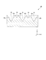
- FIG. 1 is a sectional view showing a schematic configuration of a daylighting film according to the first embodiment of the present invention.
- FIG. 2 is a schematic cross-sectional view showing the light traveling direction in the daylighting film according to the first embodiment of the present invention.
- the X direction is the normal direction of the base material of the daylighting film
- the Y direction is a direction orthogonal to the X direction
- the Z direction is a direction orthogonal to the X direction and the Y direction.
- the daylighting film 10 of the present embodiment includes a base material 11 having a light transmitting property and a plurality of light transmitting properties provided adjacent to each other on one surface 11 a of the base material 11.
- a plurality of second protrusions 14 made of the same material as that of the first protrusions 12.
- the height of the second protrusion 14 with respect to the one surface 11a of the base 11 (height of the second protrusion 14 in the normal direction (X direction) of the base 11) h 2, from (normal height direction (X direction) of the first protrusion 12 of the base member 11) h 1 of the first one of the surfaces 11a of the reference height of the base material 11 of the protrusion 12 Is also low.
- the edge of the 1st projection part 12 and the edge of the 2nd projection part 14 which mutually adjoin are contacting.
- the first protrusion 12 is inclined in different directions with respect to the one surface 11a of the base material 11, and is opposed to a pair of inclined surfaces (side surfaces) 12a and 12b, and a pair of opposed inclined surfaces (side surfaces). 12c, 12d.
- the second protrusion 14 is inclined in different directions with respect to the one surface 11a of the base material 11, and has a pair of opposed inclined surfaces (side surfaces) 14a and 14b.
- the inclined surface 12a of the first protrusion 12 and the inclined surface 14a of the second protrusion 14 have the same inclination with respect to the one surface 11a of the substrate 11. It is preferable that the inclined surface 12b of the first protrusion 12 and the inclined surface 14b of the second protrusion 14 have the same inclination with respect to the one surface 11a of the substrate 11.
- a substrate made of a resin such as a thermoplastic polymer, a thermosetting resin, or a photopolymerizable resin is generally used.
- a base material 11 for example, a light-transmitting material made of an acrylic polymer, an olefin polymer, a vinyl polymer, a cellulose polymer, an amide polymer, a fluorine polymer, a urethane polymer, a silicone polymer, an imide polymer, or the like.
- a substrate is used.
- the substrate 11 examples include a triacetyl cellulose (TAC) film, a polyethylene terephthalate (PET) film, a cycloolefin polymer (COP) film, a polycarbonate (PC) film, a polyethylene naphthalate (PEN) film, and a polyether.
- a light-transmitting substrate such as a sulfone (PES) film or a polyimide (PI) film is used.
- the light transmittance of the base material 11 in the present embodiment means that the total light transmittance defined in JIS K7361-1 is 90% or more. When the total light transmittance of the base material 11 is 90% or more, the base material 11 can obtain sufficient transparency.
- the 1st projection part 12 and the 2nd projection part 14 contain resin, such as an acrylic resin, an epoxy resin, and a silicone resin, for example, and are comprised with the organic material which has a light transmittance and photosensitivity.
- resin such as an acrylic resin, an epoxy resin, and a silicone resin, for example
- the organic material a mixture obtained by mixing the above resin with a polymerization initiator, a coupling agent, a monomer, an organic solvent, and the like is used.
- the polymerization initiator may contain various additional components such as a stabilizer, an inhibitor, a plasticizer, a fluorescent brightening agent, a release agent, a chain transfer agent, and other photopolymerizable monomers.
- the organic material a light-transmitting organic material described in Japanese Patent No. 41299991 is used.
- the total light transmittance of the first protrusion 12 and the second protrusion 14 is preferably 90% or more in accordance with JIS K7361-1. When the total light transmittance of the first protrusion 12 and the second protrusion 14 is 90% or more, the first protrusion 12 and the second protrusion 14 are sufficiently transparent.
- Each of the plurality of first protrusions 12 has a longitudinal direction substantially in one direction (Y direction), and the one direction is arranged in a direction parallel to one side of the substrate 11 having a rectangular shape. Yes.
- each of the plurality of first protrusions 12 is configured as a stripe-shaped protrusion having a constant width extending in the Y direction.
- the longitudinal directions of the plurality of first protrusions 12 are each arranged in a direction parallel to one side of the substrate 11 having a rectangular shape.
- the shape of the cross section (XZ cross section) parallel to the width direction of the first protrusion 12 in each of the plurality of first protrusions 12 is a trapezoid, a triangle, or a polygon that is a pentagon or more.
- FIG. 1 the case where the shape of the cross section parallel to the width direction of the 1st projection part 12 is a pentagon is shown.
- Each of the plurality of second protrusions 14 has a longitudinal direction in approximately one direction (Y direction), and the one direction is arranged in a direction parallel to one side of the substrate 11 having a rectangular shape. Yes.
- each of the plurality of second protrusions 14 is configured as a stripe-shaped protrusion having a constant width extending in the Y direction.
- the longitudinal directions of the plurality of second protrusions 14 are each arranged in a direction parallel to one side of the substrate 11 having a rectangular shape.
- the shape of the cross section (XZ cross section) parallel to the width direction of the second protrusion 14 in each of the plurality of second protrusions 14 is a trapezoid, a triangle, or a pentagon or more polygon. In FIG. 1, the case where the shape of the cross section parallel to the width direction of the 2nd projection part 14 is a triangle is shown.
- width w 1 in the lateral direction of the plurality of first protrusions 12 is approximately equal.
- the width w 1 in the short direction of the first protrusion 12 is, for example, 10 ⁇ m to 50 ⁇ m.
- height referenced to the one surface 11a of the base material 11 of the plurality of first protrusions 12 h 1 are roughly equal.
- the height h 1 of the first protrusion 12 is, for example, 10 ⁇ m to 100 ⁇ m.
- a first inclined surface (side surface) 12a of the protrusion 12, when the one angle alpha 1 of the angle between the surface 11a of the substrate 11, the angle alpha 1 of the plurality of first protrusions 12 are all Are equal.
- the inclined surface (side surface) 12b of the first protrusion 12, when the one angle an angle alpha 2 between the surface 11a of the substrate 11, the angle alpha 2 of the plurality of first protrusions 12 are all Are equal.
- the angle ⁇ 1 of the first protrusion 12 is, for example, 60 ° to 80 °.
- Angle alpha 2 of the first protrusion 12 is, for example, 35 ° ⁇ 60 °.
- width w 2 in the lateral direction of the plurality of second protrusions 14 it may not be equal.
- the intervals between the first protrusions 12 may be formed unevenly, and accordingly, the widths w 2 in the short direction of the plurality of second protrusions 14 may be different from each other.
- the width w 2 in the short direction of the second protrusion 14 is smaller than the width w 1 in the short direction of the first protrusion 12 (w 2 ⁇ w 1 ).
- the angle ⁇ 3 of the second protrusion 14 is substantially equal to the angle ⁇ 1 of the first protrusion 12.
- the angle ⁇ 4 of the second protrusion 14 is substantially equal to the angle ⁇ 2 of the first protrusion 12.
- the gap 13 is filled with a gas such as air, and its refractive index is approximately 1.
- a gas such as air
- refractive index of the gap 13 is 1
- the interface between the gap 13 and the first protrusion 12 and the second protrusion 14 (inclined surfaces (side surfaces) 12a, 12b of the first protrusion 12).
- 12c, 12d, and the inclined angle (side surfaces) 14a, 14b) of the second projecting portion 14 are configured to be minimized.
- the gap 13 is an air layer if it is made of air, but the gap 13 may be an inert gas layer made of an inert gas such as nitrogen, and is in a reduced pressure state. It may be a decompression layer.
- the daylighting film 10 is affixed to the glass substrate of the window glass so that the alignment direction of the first protrusions 12 and the second protrusions 14 is the vertical direction.
- the light L 1 incident on the inside of the first protrusion 12 from the inclined surface 12 a of the first protrusion 12 is The light is refracted on the other surface 11 b of the material 11 and emitted toward the lower side of the daylighting film 10.
- the light emitted from the substrate 11 does not become glare (the emission angle passes below the glare range).
- light L 5 of the second protrusion 14 has passed the position that does not exist in the gap portion 13, after exiting the second surface 11b, a glare.
- the light L 2 incident on the inside of the second protrusion 14 from the inclined surface 14 a of the second protrusion 14 is the other surface 11 b of the substrate 11.
- the light is refracted and emitted toward the lower side of the daylighting film 10.
- the light emitted from the substrate 11 does not become glare (the emission angle passes below the glare range).
- light L 5 of the second protrusion 14 has passed the position that does not exist in the gap portion 13, after exiting the second surface 11b, a glare.
- the light inserted from above the daylighting film 10 the light L 3 incident on the inside of the first protrusion 12 from the inclined surface 12 b of the first protrusion 12 is the other surface 11 b of the substrate 11. Is refracted and emitted toward the upper side of the daylighting film 10.
- the light L 4 incident on the inside of the second protrusion 14 from the inclined surface 14 b of the second protrusion 14 is the other surface 11 b of the substrate 11. Is refracted and emitted toward the upper side of the daylighting film 10.
- the light emitted toward the upper side of the optical film 10 is guided to the indoor ceiling or the interior, and illuminates the interior brightly.
- the inclined surfaces 12a, 12b, 12c, and 12d on the opposite side of the first protrusion 12 from the substrate 11 are configured as light incident end surfaces, and the first protrusion 12 has the substrate 11 side.
- the end face 12e is configured as a light exit end face.
- the inclined surfaces 14a and 14b on the opposite side to the base material 11 of the second protrusion 14 are configured as a light incident end surface, and the end surface 14c on the base material 11 side of the second protrusion 14 is a light emission end surface. It is configured as.
- the case where one second protrusion 14 is provided in all the gaps 13 formed between the plurality of first protrusions 12 is illustrated.
- the form is not limited to this.
- the second protrusion 14 is provided in at least one of the gaps 13 formed between the plurality of first protrusions 12. That's fine.
- two or more second protrusions 14 may be provided in the gap 13.
- edge of the 1st projection part 12 and the edge of the 2nd projection part 14 which adjoin each other was illustrated in this embodiment, this embodiment is not limited to this.
- the end surface on the base material 11 side of the first protrusions 12 adjacent to each other and the end surface on the base material 11 side of the second protrusions 14 overlap.
- the edge of the 1st projection part 12 which adjoins mutually, and the edge of the 2nd projection part 14 may be connected.
- the overlapping degree of the 1st projection part 12 and the 2nd projection part 14 may differ individually.
- first protrusions 12 and the second protrusions 14 adjacent to each other a part of the first protrusions 12 and the second protrusions 14 adjacent to each other may not be in contact.
- part of the second protrusion 14 may be in contact with each other. That is, as shown in FIG. 6, the plurality of first protrusions 12 and second protrusions 14 include a pair of first protrusions 12 and second protrusions 14 that are adjacent to each other.
- the structure which is in contact with each other is included, and other parts of the first protrusion 12 and the second protrusion 14 adjacent to each other may not be in contact.
- the case where the 1st projection part 12 had a pair of opposing inclined surface (side surface) 12a, 12b and a pair of inclined surface (side surface) 12c, 12d was illustrated.
- the present embodiment is not limited to this.
- the first protrusion 12 only needs to have at least one pair of opposed inclined surfaces 12 a and 12 b.
- the case where the second protrusion 14 has a pair of opposed inclined surfaces (side surfaces) 14a and 14b is illustrated, but the present embodiment is not limited to this.
- the second protrusion 14 may have two or more pairs of opposed inclined surfaces. For example, as shown to FIG.
- the 2nd projection part 14 may have a pair of inclined surface 14a, 14b and a pair of inclined surface 14d, 14e which oppose.
- the second protrusion 14 has a mixture of a pair of opposed inclined surfaces (side surfaces) and a pair of opposed pair of inclined surfaces (side surfaces). May be.
- a protective member 15 having a light transmission property is provided on the opposite side of the substrate 11 with the plurality of first protrusions 12 and the second protrusions 14 interposed therebetween. May be provided.
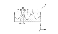
- FIG. 10 is sectional drawing which shows schematic structure of the metal mold
- the Z direction is the normal direction of the main body of the daylighting film forming mold
- the Y direction is a direction orthogonal to the Z direction
- the X direction is a direction orthogonal to the Z direction and the Y direction.
- a lighting film forming mold (hereinafter abbreviated as “mold”) 20 of the present embodiment includes a main body 21 made of metal and one surface 21 a of the main body 21 (FIG. 10). Then, it is indicated by a broken line.) A plurality of first recesses 22 provided adjacent to each other on the side, and a second provided adjacent to the first recess 22 between the first recesses 22. And a recess 23.
- a depth d 2 (a depth in the normal direction (Z direction) of the main body portion 21) d 2 with respect to the one surface 21 a of the main body portion 21 of the second concave portion 23 is the first concave portion 22. It is shallower in (depth of the normal direction (Z direction of the main body 21)) one face 21a of the reference height of the main body portion 21 than d 1.
- the opening edge of the first recess 22 adjacent to each other and the opening edge of the second recess 23 are in contact with each other.
- the first concave portion 22 is inclined in different directions with respect to the one surface 21a of the main body portion 21, and has a pair of inner side surfaces 22a and 22b and a pair of inner side surfaces 22c and 22d.
- the second recess 23 is inclined in different directions with respect to the one surface 21 a of the main body 21 and has a pair of inner side surfaces 23 a and 23 b facing each other.
- the inner surface 22 a of the first recess 22 and the inner surface 23 a of the second recess 23 have the same inclination with respect to the one surface 21 a of the main body 21.
- the inner surface 22b of the first recess 22 and the inner surface 23b of the second recess 23 preferably have the same inclination with respect to the one surface 21a of the main body 21.
- Each of the plurality of first recesses 22 has a longitudinal direction substantially in one direction (Y direction), and the one direction is arranged in a direction parallel to one side of the main body 21 having a rectangular shape, for example. ing.
- each of the plurality of first recesses 22 is configured as a striped recess having a constant width extending in the Y direction.
- the longitudinal directions of the plurality of first recesses 22 are each arranged in a direction parallel to one side of the main body 21 having a rectangular shape.
- the shape of the cross section (XZ cross section) parallel to the width direction of the first recess 22 in each of the plurality of first recesses 22 is a trapezoid, a triangle, or a polygon that is a pentagon or more.
- FIG. 10 shows a case where the shape of the cross section parallel to the width direction of the first recess 22 is a pentagon (when one surface 21a of the main body 21 is the bottom).
- Each of the plurality of second recesses 23 has a longitudinal direction substantially in one direction (Y direction), and the one direction is arranged in a direction parallel to one side of the main body 21 having a rectangular shape, for example. ing.
- each of the plurality of second recesses 23 is configured as a striped recess having a constant width extending in the Y direction.
- the longitudinal directions of the plurality of second recesses 23 are each arranged in a direction parallel to one side of the main body 21 having a rectangular shape.
- the shape of the cross section (XZ cross section) parallel to the width direction of the second recess 23 in each of the plurality of second recesses 23 is a trapezoid, a triangle, or a polygon that is a pentagon or more.
- FIG. 10 shows a case where the shape of the cross section parallel to the width direction of the second recess 23 is a triangle (when one surface 21a of the main body 21 is the base).
- the width w 11 of the lateral direction of the plurality of first recess 22 is approximately equal.
- the width w 11 in the short direction of the first recess 22 is, for example, 10 ⁇ m to 50 ⁇ m.
- the depth referenced to the one surface 21a of the body portion 21 of the plurality of first concave portions 22 d 1 is approximately equal.
- the depth d 1 of the first recess 22 is, for example, 10 ⁇ m to 100 ⁇ m.
- angle alpha 11 of the first recess 22 is substantially equal.
- inner side surface 22b of the first recess 22 when the angle alpha 12 the angle between one surface 21a of the body portion 21, the angle alpha 12 of the plurality of first recess 22 is substantially equal.
- Angle alpha 11 of the first recess 22 is, for example, 60 ° ⁇ 80 °.
- Angle alpha 12 of the first recess 22 is, for example, 35 ° ⁇ 60 °.
- the width w 12 of the plurality of second lateral direction of the recess 23 may be unequal.
- the first recesses 22 are formed unevenly, and as a result, the widths w 12 in the short direction of the plurality of second short recesses 23 may be different from each other.
- the width w 12 in the short direction of the second recess 23 is smaller than the width w 11 in the short direction of the first recess 22 (w 12 ⁇ w 11 ).
- the angle ⁇ 13 of the second recess 23 is substantially equal to the angle ⁇ 11 of the first recess 22.
- the angle ⁇ 14 of the second recess 23 is substantially equal to the angle ⁇ 12 of the first recess 22.
- the first concave portion 22 and the second concave portion 23 are cut with a cutting tool having the same shape.
- Cutting the second recess 23 with a cutting tool having the same shape as the first recess 22 has mainly two advantages.
- One is that the taper angle with respect to the substrate can be formed to the same angle. If the angle is the same, the first protrusion 12 formed by the first recess 22 is at an angle that allows the sun rays to be directed upward as much as possible. And light rays in the glare direction are suppressed.
- Second by using the same bite, it is not necessary to prepare a separate tool for the second recess 23, and no additional tool is required. That is, the first recess 22 and the second recess 23 can be cut with the same cutting tool, and it is not necessary to prepare a cutting tool according to each recess.
- the 1st recessed part 22 and the 2nd recessed part 23 can be cut in the same process, and the addition of the manufacturing process for providing the 2nd projection part 14 part does not generate
- the metal which comprises the main-body part 21 is not specifically limited, For example, copper and nickel are mentioned.
- the daylighting film 10 can be easily formed.
- the case where one second concave portion 23 is provided in all the regions between the plurality of first concave portions 22 in the main body portion 21 is exemplified. It is not limited. In the present embodiment, as shown in FIG. 11, the second recess 23 may be provided in at least one of the regions between the plurality of first recesses 22 in the main body 21. Moreover, in the area
- this embodiment is not limited to this.
- a part of the inner side surface 22c on the one surface 21a side of the main body portion 21 and the inner side surface 23b of the second concave portion 23 in the first concave portions 22 adjacent to each other are adjacent to each other so that a part of the inner side surface 22d on the one surface 21a side of the main body portion 21 and a part of the inner side surface 23a of the second recess portion 23 overlap each other in the first recesses 22 adjacent to each other.
- the edge of the 1st recessed part 22 and the edge of the 2nd recessed part 23 may be connected. Moreover, as shown to FIG. 13B, the overlapping degree of the 1st recessed part 22 and the 2nd recessed part 23 may differ individually. Further, in all of the first recess 22 and the second recess 23 adjacent to each other, the first recess 22 and the second recess 23 adjacent to each other may not be in contact with each other. For example, in a part of the first recesses 22 and the second recesses 23 among the plurality of first recesses 22 and the second recesses 23, a pair of the first recesses 22 and the second recesses adjacent to each other. A part of 23 may touch. That is, as shown in FIG.
- first recesses 22 and second recesses 23 are in contact with a part of a pair of first recesses 22 and second recesses 23 adjacent to each other.
- the other adjacent first recess 22 and second recess 23 may not be in contact with each other.
- the case where the first concave portion 22 has a pair of opposed inner side surfaces 22a and 22b and a pair of inner side surfaces 22c and 22d is illustrated. It is not limited to. In the present embodiment, as shown in FIG. 15, the first recess 22 only needs to have at least one pair of opposed inner side surfaces 22a and 22b. In the present embodiment, the case where the second concave portion 23 has a pair of opposed inner side surfaces 23a and 23b is illustrated, but the present embodiment is not limited to this. In the present embodiment, the second recess 23 may have two or more pairs of opposed inner surfaces. For example, as shown to FIG.
- the 2nd recessed part 23 may have a pair of inner surface 23a, 23b which opposes, and a pair of inner surface 23c, 23d. Further, as shown in FIG. 16B, the second recess 23 may include a mixture of a pair of opposed inner surfaces and a combination of two or more pairs of opposed inner surfaces.
- FIG. 17 to 19 are schematic cross-sectional views showing a method for manufacturing a daylighting film according to a third embodiment of the present invention.
- 17 to 19 the same components as those of the daylighting film of the first embodiment shown in FIG. 1 and the daylighting film forming mold of the second embodiment shown in FIG. The description is omitted.
- the Z direction is the normal direction of the main body of the daylighting film forming mold
- the Y direction is a direction orthogonal to the Z direction
- the X direction is a direction orthogonal to the Z direction and the Y direction.
- the manufacturing method of the daylighting film of this embodiment is a method using the daylighting film forming mold of the second embodiment described above. As shown in FIG. 17, a light transmissive resin 31 is applied to one surface 21 a of the main body 21 of the mold 20, and the resin 31 is filled in the first recess 22 and the second recess 23. (Filling step).
- a resin such as a thermoplastic polymer, a thermosetting resin, or a photopolymerizable resin is generally used.
- a resin 31 include acrylic polymers, olefin polymers, vinyl polymers, cellulose polymers, amide polymers, fluorine polymers, urethane polymers, silicone polymers, imide polymers, and the like.
- the resin 31 is filled in the first recess 22 and the second recess 23, and the resin 31 filled in the first recess 22 and the second recess 23. Further, a light-transmitting resin 32 serving as a base material for the daylighting film is applied to a predetermined thickness.
- the light transmissive resin 32 the same resin as the light transmissive resin 31 is used.
- the resin 31 and the resin 32 are integrally molded. The resin 31 is also applied to one surface 21 a of the main body 21 of the mold 20, and the resin 31 cured on the surface of the mold 20 becomes a substrate 33. The resin 31 and the substrate 33 are formed by one curing.
- a light-transmitting base material 33 having a predetermined thickness which serves as a base material for the daylighting film, may be pasted on 31.
- the resin 31 and the resin 32 are cured, and the base material 11 made of the resin 32 and a plurality of resins 31 made of the resin 31 provided adjacent to each other on one surface 11 a of the base material 11.
- the daylighting film 10 which has the 1st projection part 12 and the several 2nd projection part 14 which consists of resin 31 provided in the one surface 11a of the base material 11 adjacent to the 1st projection part 12.
- the resin 31 is cured and the resin 31 is fixed to the base material 33, and is adjacent to the base material 11 (base material 33) and the one surface 11 a of the base material 11.
- the daylighting film 10 is peeled from the daylighting film forming mold 20 to obtain the daylighting film 10 (peeling step).
- the daylighting film 10 can be easily formed.
- FIG. 20 is a cross-sectional view showing a schematic configuration of a daylighting film according to the fourth embodiment of the present invention.
- FIG. 21 is a schematic sectional drawing which shows the advancing direction of a light beam in the daylighting film which is 4th Embodiment of this invention.
- the X direction is the normal direction of the base material of the daylighting film
- the Y direction is a direction orthogonal to the X direction
- the Z direction is a direction orthogonal to the X direction and the Y direction.
- FIG. 20 is a cross-sectional view showing a schematic configuration of a daylighting film according to the fourth embodiment of the present invention.
- FIG. 21 is a schematic sectional drawing which shows the advancing direction of a light beam in the daylighting film which is 4th Embodiment of this invention.
- the X direction is the normal direction of the base material of the daylighting film
- the Y direction is a direction orthogonal to the X direction
- the Z direction is a direction orthogon
- the daylighting film 40 of the present embodiment includes a base 41 having optical transparency and a plurality of optical transparencys provided adjacent to each other on one surface 41 a of the base 41. 1 protrusion 42, a gap 43 provided between the first protrusions 42, and one surface 41 a of the substrate 41, adjacent to the gap 43, adjacent to the first protrusion 42. And a plurality of second protrusions 44 made of the same material as that of the first protrusions 42.
- a height (a height in the normal direction (X direction) of the base material 41 of the second protrusion 44) with respect to the one surface 41a of the base material 41 of the second protrusion 44 is h. 12, than the first protrusion (the height of the normal direction (X direction of the base 41 of the first protrusion 42)) one surface 41a of the reference height of the base material 41 of the 42 h 11 Is also low. Further, in the daylighting film 40, the edge of the first protrusion 42 and the edge of the second protrusion 44 that are adjacent to each other are in contact with each other.
- the first protrusions 42 are inclined in different directions with respect to the one surface 41a of the substrate 11, and are opposed to each other with a pair of inclined surfaces (side surfaces) 42a and 42b and a pair of inclined surfaces (side surfaces) 42c, 42d.
- the second protrusions 44 are inclined in different directions with respect to the one surface 41a of the base material 11, and are opposed to each other with a pair of inclined surfaces (side surfaces) 44a and 44b and a pair of inclined surfaces (side surfaces) 44c, 44d.
- the shape of the first protrusion 42 and the shape of the second protrusion 44 are similar. That is, it is preferable that the inclined surface 42 a of the first protrusion 42 and the inclined surface 44 a of the second protrusion 44 have the same inclination with respect to the one surface 41 a of the substrate 41. It is preferable that the inclined surface 42 b of the first protrusion 42 and the inclined surface 44 b of the second protrusion 44 have the same inclination with respect to the one surface 41 a of the substrate 41. It is preferable that the inclined surface 42 c of the first protrusion 42 and the inclined surface 44 c of the second protrusion 44 have the same inclination with respect to the one surface 41 a of the substrate 41. It is preferable that the inclined surface 42 d of the first protrusion 42 and the inclined surface 44 d of the second protrusion 44 have the same inclination with respect to the one surface 41 a of the substrate 41.
- the base material 41 As the base material 41, the same base material as the base material 11 is used.
- the light transmittance of the substrate 41 in the present embodiment means that the total light transmittance defined in JIS K7361-1 is 90% or more. When the total light transmittance of the base material 41 is 90% or more, the base material 41 can obtain sufficient transparency.
- the first protrusion 42 and the second protrusion 44 are made of the same organic material as the first protrusion 12 and the second protrusion 14 described above.
- the total light transmittance of the first protrusion 42 and the second protrusion 44 is preferably 90% or more in accordance with JIS K7361-1. When the total light transmittance of the first protrusion 42 and the second protrusion 44 is 90% or more, the first protrusion 42 and the second protrusion 44 can have sufficient transparency.
- Each of the plurality of first protrusions 42 has a longitudinal direction substantially in one direction (Y direction), and the one direction is arranged in a direction parallel to one side of the base material 41 having a rectangular shape. Yes.
- each of the plurality of first protrusions 42 is configured as a stripe-shaped protrusion having a constant width extending in the Y direction.
- the longitudinal directions of the plurality of first protrusions 42 are each arranged in a direction parallel to one side of the base material 41 having a rectangular shape.
- the shape of the cross section (XZ cross section) parallel to the width direction of the first protrusion 42 in each of the plurality of first protrusions 42 is a trapezoid, a triangle, or a polygon that is a pentagon or more.
- FIG. 6 the case where the shape of the cross section parallel to the width direction of the 1st projection part 42 is a pentagon is shown.
- Each of the plurality of second protrusions 44 has a longitudinal direction in approximately one direction (Y direction), and the one direction is arranged in a direction parallel to one side of the base material 41 having a rectangular shape. Yes.
- each of the plurality of second protrusions 44 is configured as a stripe-shaped protrusion having a constant width extending in the Y direction.
- the longitudinal directions of the plurality of second protrusions 44 are each arranged in a direction parallel to one side of the base material 41 having a rectangular shape.
- the shape of the cross section (XZ cross section) parallel to the width direction of the second protrusion 44 in each of the plurality of second protrusions 44 is a trapezoid, a triangle, or a polygon that is a pentagon or more.
- FIG. 6 the case where the shape of the cross section parallel to the width direction of the 2nd projection part 44 is a pentagon is shown.
- the width w 21 of the lateral direction of the plurality of first protrusions 42 is approximately equal.
- the width w 21 in the short direction of the first protrusion 42 is, for example, 10 ⁇ m to 50 ⁇ m.
- the height (height in the normal direction (X direction) of the base material 41 of the first protrusion 42) with respect to the one surface 11a of the base material 41 of the plurality of first protrusions 42 h 11 Are roughly equal.
- the height h 11 of the first protrusion 42 is, for example, 10 ⁇ m to 100 ⁇ m.
- the inclined surface (side surface) 42a of the first protrusion 42 when the angle alpha 21 the angle between one surface 41a of the substrate 41, the angle alpha 21 of the plurality of first protrusions 42 are all Are equal.
- the inclined surface (side surface) 42b of the first protrusion 42 when the angle alpha 22 the angle between one surface 41a of the substrate 41, the angle alpha 22 of the plurality of first protrusions 42 are all Are equal.
- the angle ⁇ 21 of the first protrusion 42 is, for example, 60 ° to 80 °.
- the angle ⁇ 22 of the first protrusion 42 is, for example, 35 ° to 60 °.
- the width w 22 of the lateral direction of the plurality of second protruding portions 44 may be unequal.
- the first protrusions 42 may be formed unevenly.
- the widths w 22 in the short direction of the plurality of second protrusions 44 may be different from each other.
- the width w 22 in the short direction of the second protrusion 44 is smaller than the width w 21 in the short direction of the first protrusion 42 (w 22 ⁇ w 21 ).
- the inclined surface (side surface) 44a of the second protrusion 44 when the angle of the angle alpha 23 with one surface 41a of the substrate 41, the angle alpha 23 of the plurality of second protrusions 44 is approximately Are equal.
- the inclined surface (side surface) 44b of the second projecting portion 44 when the angle alpha 24 the angle between one surface 41a of the substrate 41, the angle alpha 24 of the plurality of second protrusions 44 is approximately Are equal.
- the angle ⁇ 23 of the second protrusion 44 is substantially equal to the angle ⁇ 21 of the first protrusion 42.
- the angle ⁇ 24 of the second protrusion 44 is substantially equal to the angle ⁇ 22 of the first protrusion 42.
- the air gap 43 is filled with gas such as air, and its refractive index is approximately 1.
- gas such as air
- its refractive index is approximately 1.
- the interface between the gap 43 and the first protrusion 42 and the second protrusion 44 (inclined surfaces (side surfaces) 42a and 42b of the first protrusion 42).
- 42c, 42d, and the inclined angle (side surfaces) 44a, 44b, 44c, 44d) of the second protrusion 44 are configured to be the smallest.
- the gap portion 43 is an air layer if it is made of air, but the gap portion 43 may be an inert gas layer made of an inert gas such as nitrogen and is in a reduced pressure state. It may be a decompression layer.
- the daylighting film 40 is attached to the glass substrate of the window glass so that the arrangement direction of the first protrusions 42 and the second protrusions 44 is the vertical direction.
- the light L 11 incident on the inside of the first protrusion 42 from the inclined surface 42 a of the first protrusion 42 is After being totally reflected at the interface between the first protrusion 42 and the gap 43 and changing the traveling direction upward, the light is refracted by the other surface 41 b of the base material 41 and emitted toward the upper side of the daylighting film 40.
- the inclined surface 44a of the second protrusion 44, the light L 12 which enters the second projection portion 44, the second protrusion 44 and the air gap After being totally reflected at the interface with the portion 43 and changing the traveling direction upward, it is refracted by the other surface 41 b of the base material 41 and emitted toward the upper side of the daylighting film 40.
- the light L 13 incident on the inside of the first protrusion 42 from the inclined surface 42 b of the first protrusion 42 is the other surface 41 b of the base material 41. Is refracted and emitted toward the upper side of the daylighting film 40.
- the light L 14 incident on the inside of the second protrusion 44 from the inclined surface 44 b of the second protrusion 44 is the other surface 41 b of the base material 41. Is refracted and emitted toward the upper side of the daylighting film 40. Thus, the light emitted toward the upper side of the daylighting film 40 is guided to the indoor ceiling or the back of the indoor to illuminate the interior brightly.
- the inclined surfaces 42a, 42b, 42c, and 42d on the opposite side of the first protrusion 42 from the substrate 41 are configured as light incident end surfaces, and the first protrusion 42 is on the substrate 41 side.
- the end face 42e is configured as a light exit end face.
- inclined surfaces 44a, 44b, 44c, 44d on the opposite side of the base material 41 of the second protrusion 44 are configured as light incident end surfaces, and an end surface 44e of the second protrusion 44 on the base material 41 side. Is configured as a light exit end face.
- a light-transmitting base 41 and a plurality of light-transmitting first protrusions 42 provided adjacent to each other on one surface 41 a of the base 41.
- a plurality of second protrusions 44 made of the same material as the first protrusions 42 on the one surface 41a of the base material 41, adjacent to the first protrusions 42, and
- the angle ⁇ 23 of the second protrusion 44 is substantially equal to the angle ⁇ 21 of the first protrusion 42, and the angle ⁇ 24 of the second protrusion 44 is the angle ⁇ of the first protrusion 42.
- the lights L 12 and L 14 incident on the inside of the second projecting portion 44 are sampled in the same manner as the lights L 11 and L 13 incident on the inside of the first projecting portion 42. Since the light can be emitted upward from the film 40, the outside light is directed toward the indoor ceiling. Can be allowed to proceed, it is possible to suppress the feel the glare of the person you are indoors.
- one second protrusion 44 is provided in all the gaps 43 formed between the plurality of first protrusions 42 .
- the form is not limited to this.
- a second protrusion 44 is provided in at least one of the gaps 43 formed between the plurality of first protrusions 42. That's fine.
- the edge of the first protrusion 42 and the edge of the second protrusion 44 that are adjacent to each other is illustrated, but the present embodiment is not limited to this.
- the end surface on the base material 41 side of the first protrusions 42 adjacent to each other overlaps the part of the end surface on the base material 41 side of the second protrusions 44.
- the edge of the 1st projection part 42 which adjoins mutually, and the edge of the 2nd projection part 44 may be connected.
- the first protrusions 42 and the second protrusions 44 adjacent to each other may not be in contact with each other.
- the case where the 1st projection part 42 had a pair of opposing inclined surface (side surface) 42a, 42b and a pair of inclined surface (side surface) 42c, 42d was illustrated.
- the present embodiment is not limited to this.
- the first protrusion 42 only needs to have at least one pair of opposed inclined surfaces 42a and 42b.
- the case where the 2nd projection part 44 had a pair of opposing inclined surface (side surface) 44a, 44b and a pair of inclined surface (side surface) 44c, 44d was illustrated.
- the present embodiment is not limited to this.
- the second protrusion 44 only needs to have at least one pair of opposed inclined surfaces 44a and 44b.
- the present embodiment the case where the entire shape of the first protrusion 42 and the entire shape of the second protrusion 44 are similar is illustrated, but the present embodiment is not limited to this.
- the shape of the part which has a pair of inclined surfaces 44c and 44d should just be similar.
- the present embodiment the case where the first protrusion 42 and the second protrusion 44 are exposed on the one surface 41a of the base material 41 is illustrated, but the present embodiment is not limited to this. .
- the protective member 25 having light transmittance on the opposite side of the base material 41 across the plurality of first protrusions 42 and the second protrusions 44. May be provided.
- FIG. 29 is a cross-sectional view showing a schematic configuration of a lighting film forming mold according to a fifth embodiment of the present invention.
- the Z direction is the normal direction of the main body of the daylighting film forming mold
- the Y direction is a direction orthogonal to the Z direction
- the X direction is a direction orthogonal to the Z direction and the Y direction.
- a daylighting film forming mold (hereinafter abbreviated as “mold”) 50 includes a main body 51 made of metal and one surface 51a of the main body 51 (FIG. 29).
- the first recess 52 provided adjacent to each other on the side
- the second recess 52 provided adjacent to the first recess 52 between the first recesses 52.
- a recess 53 is a recess 53.
- the depth d 12 (depth in the normal direction (Z direction) of the main body 51) d 12 with respect to the one surface 51 a of the main body 51 of the second recess 53 is the first recess 52. of (depth of the normal direction (Z direction of the main body 51)) height relative to the one surface 51a of the body portion 51 is shallower than d 11.
- the opening edge of the first recess 52 adjacent to each other and the opening edge of the second recess 53 are in contact with each other.
- the first recess 52 is inclined in different directions with respect to the one surface 51a of the main body 51, and has a pair of opposed inner side surfaces 52a and 52b and a pair of inner side surfaces 52c and 52d.
- the second recess 53 is inclined in different directions with respect to the one surface 51a of the main body 51, and has a pair of inner side surfaces 54a and 54b and a pair of inner side surfaces 54c and 54d. .
- the inner surface 52a of the first recess 52 and the inner surface 53a of the second recess 53 have the same inclination with respect to the one surface 51a of the main body 51. It is preferable that the inner surface 52b of the first recess 52 and the inner surface 53b of the second recess 53 have the same inclination with respect to the one surface 51a of the main body 51. It is preferable that the inner surface 52 c of the first recess 52 and the inner surface 53 c of the second recess 53 have the same inclination with respect to the one surface 51 a of the main body 51.
- the inner surface 52d of the first recess 52 and the inner surface 53d of the second recess 53 preferably have the same inclination with respect to the one surface 51a of the main body 51.
- Each of the plurality of first recesses 52 has a longitudinal direction substantially in one direction (Y direction), and the one direction is arranged in a direction parallel to one side of the main body 51 having a rectangular shape, for example. ing.
- each of the plurality of first recesses 52 is configured as a striped recess having a constant width extending in the Y direction.
- the longitudinal directions of the plurality of first recesses 52 are each arranged in a direction parallel to one side of the main body 51 having a rectangular shape.
- the shape of the cross section (XZ cross section) parallel to the width direction of the first recess 52 in each of the plurality of first recesses 52 is a trapezoid, a triangle, or a polygon that is a pentagon or more.
- FIG. 29 shows a case where the shape of the cross section parallel to the width direction of the first recess 52 is a pentagon (when one surface 51a of the main body 51 is the base).
- Each of the plurality of second recesses 53 has a longitudinal direction substantially in one direction (Y direction), and the one direction is arranged in a direction parallel to one side of the main body 51 having a rectangular shape, for example. ing.
- each of the plurality of second recesses 53 is configured as a striped recess having a constant width extending in the Y direction.
- the longitudinal directions of the plurality of second recesses 53 are each arranged in a direction parallel to one side of the main body 51 having a rectangular shape.
- the shape of the cross section (XZ cross section) parallel to the width direction of the second recess 53 in each of the plurality of second recesses 53 is a trapezoid, a triangle, or a polygon that is a pentagon or more.
- FIG. 29 shows a case where the shape of the cross section parallel to the width direction of the second recess 53 is a pentagon (when one surface 51a of the main body 51 is the base).
- the width w 31 of the lateral direction of the plurality of first recess 52 is approximately equal.
- the width w 31 in the short direction of the first recess 52 is, for example, 10 ⁇ m to 50 ⁇ m.
- depth relative to the one surface 51a of the plurality of the main body portion 51 of the first recess 52 d 11 is approximately equal.
- the depth d 11 of the first recess 52 is, for example, 10 ⁇ m to 100 ⁇ m.
- the angle ⁇ 31 of the first recess 52 is, for example, 60 ° to 80 °.
- the angle ⁇ 32 of the first recess 52 is, for example, 35 ° to 60 °.
- the width w 32 of the lateral direction of the plurality of second recesses 53 may be unequal.
- the first recesses 52 may be formed unevenly, and as a result, the widths w 32 in the short direction of the plurality of second short direction recesses 53 may be different from each other.
- Width w 32 of the lateral direction of the second recess 53 is smaller (w 32 ⁇ w 31) than w 31 the width of the lateral direction of the first recess 52.
- the inner surface 53a of the second recess 53 when the one angle the angle alpha 33 between the surface 51a of the main body portion 51, the angle alpha 33 of the plurality of second recess 53 is substantially equal.
- the inner side surface 53b of the second recess 53 when the angle of the angle alpha 34 between the surface 51a of one of the main body portion 51, the angle alpha 34 of the plurality of second recess 53 is substantially equal.
- the angle ⁇ 33 of the second recess 53 is substantially equal to the angle ⁇ 31 of the first recess 52.
- the angle ⁇ 34 of the second recess 53 is substantially equal to the angle ⁇ 32 of the first recess 52.
- the same metal as the metal constituting the main body 21 is used as the metal constituting the main body 51.
- the daylighting film 40 can be easily formed.
- the case where one second concave portion 53 is provided in all the regions between the plurality of first concave portions 52 in the main body portion 51 is exemplified. It is not limited. In the present embodiment, as shown in FIG. 30, it is only necessary that the second recess 53 is provided in at least one of the regions between the plurality of first recesses 52 in the main body 51. Moreover, in the area
- the present embodiment is not limited to this.
- the inner side surface 53d on the one surface 51a side of the main body portion 51 in the first concave portion 52 adjacent to each other and the main body portion 51 in the second concave portion 53 so that a part of the inner side surface 53d on the side of the surface 51a overlaps.
- the edge of the 1st recessed part 52 and the edge of the 2nd recessed part 53 which mutually adjoin may be connected so that a part of inner surface 53c by the side of one surface 51a may overlap. Further, in all of the first concave portion 52 and the second concave portion 53 adjacent to each other, the first concave portion 52 and the second concave portion 53 adjacent to each other may not be in contact with each other. For example, in a part of the first recesses 52 and the second recesses 53 among the plurality of first recesses 52 and the second recesses 53, a pair of the first recesses 52 and the second recesses adjacent to each other. A part of 53 may touch. That is, as shown in FIG.
- first recesses 52 and second recesses 53 are in contact with a pair of first recesses 52 and second recesses 53 that are adjacent to each other.
- the other adjacent first recess 52 and second recess 53 may not be in contact with each other.
- the present embodiment is not limited to this. It is not limited to.
- the first recess 52 only needs to have at least one pair of opposed inner side surfaces 52a and 52b.
- the second concave portion 53 has a pair of opposed inner side surfaces 53a and 53b and a pair of inner side surfaces 53c and 53d is illustrated. It is not limited to.
- the second recess 53 only needs to have at least one pair of opposed inner surfaces.
- the second recess 53 only needs to have at least one pair of opposed inclined surfaces 53a and 53b.
- FIG. 36 to 38 are schematic cross-sectional views showing a method for manufacturing a daylighting film according to a sixth embodiment of the present invention.
- 36 to 38 the same components as those of the daylighting film of the fourth embodiment shown in FIG. 20 and the daylighting film forming mold of the fifth embodiment shown in FIG. The description is omitted.
- the Z direction is the normal direction of the main body of the daylighting film forming mold
- the Y direction is a direction orthogonal to the Z direction
- the X direction is a direction orthogonal to the Z direction and the Y direction.
- the manufacturing method of the daylighting film of this embodiment is a method using the daylighting film forming mold of the fifth embodiment described above. As shown in FIG. 36, a light transmissive resin 61 is applied to one surface 51 a of the main body 51 of the mold 50, and the resin 61 is filled into the first recess 52 and the second recess 53. (Filling step).
- the same resin 31 as described above is used as the light transmissive resin 61.
- the first recess 52 and the second recess 53 are filled with the resin 61 and the first recess 52 and the second recess 53 are filled with the resin 61.
- a light-transmitting resin 62 serving as a base material for the daylighting film is applied to a predetermined thickness.
- the light transmissive resin 62 the same resin as the light transmissive resin 61 is used.
- a light-transmitting base material 63 having a predetermined thickness, which serves as a base material for the daylighting film, may be pasted on 61.
- the resin 61 and the resin 62 are cured, and a plurality of substrates 61 made of the resin 62 and a plurality of resins 61 made adjacent to each other on the one surface 41 a of the substrate 41.
- the daylighting film 40 which has the 1st projection part 42 and the some 2nd projection part 44 which consists of resin 61 provided in the one surface 41a of the base material 41 adjacent to the 1st projection part 42. (Lighting film forming step). Further, in the daylighting film forming step, the resin 61 is cured and the resin 61 is fixed to the base 63, and is adjacent to the base 41 (base 63) and one surface 41 a of the base 41.
- FIG. The resin 61 is also applied to the surface of the mold 50, and the resin 61 cured on the surface of the mold 50 becomes the substrate 41.
- the second protrusion 44 and the substrate 41 are formed by one curing.
- the daylighting film 40 is peeled from the daylighting film forming mold 50 to obtain the daylighting film 40 (peeling step).
- the daylighting film 40 can be easily formed.
- the shape of the daylighting film such as the shape of the first protrusion and the shape of the second protrusion may be different for each substrate.
- a plurality of daylighting films may be arranged and applied to a product that controls the amount of light on the window surface such as a roll screen or a blind.
- FIG. 39 is a perspective view showing a schematic configuration of the roll screen 301.
- 40 is a cross-sectional view taken along line AA ′ of the roll screen 301 shown in FIG.
- part equivalent to the said lighting film while omitting description, the same code
- the roll screen 301 includes a daylighting screen 302 and a winding mechanism 303 that supports the daylighting screen 302 so as to be freely wound.
- the daylighting screen 302 has a light-transmitting film-like (sheet-like) base material 311 and a plurality of light-transmitting properties provided adjacent to one surface 311a of the base material 311.
- the first protrusion 312 having a gap, the gap 313 provided between the first protrusions 312, and the one surface 311 a of the base material 311, the gap 313, the first protrusion 312
- a plurality of second protrusions 314 made of the same material as that of the first protrusions 312 and provided outside through the first protrusions 312, the second protrusions 314, and the base material 311. Incorporates light.
- the daylighting screen 302 has basically the same structure as the daylighting films 10, 20, 30, and 40. However, the thickness of the base material 311 is suitable for the roll screen 301.
- the winding mechanism 303 includes a winding core (support member) 304 attached along the upper end portion of the daylighting screen 302 and a lower pipe (supporting member) attached along the lower end portion of the daylighting screen 302. Member) 305, a tension cord 306 attached to the center of the lower end of the daylighting screen 302, and a storage case 307 for storing the daylighting screen 302 wound around the winding core 304.
- the take-up mechanism 303 is a pull cord type, and is fixed at the position where the daylighting screen 302 is pulled out, or by further pulling the tensioning cord 306 from the position where it is pulled out, and the fixing is released and the daylighting screen 302 is attached to the core 304. It is possible to wind up automatically.
- the winding mechanism 303 is not limited to such a pull cord type, but may be a chain type winding mechanism that rotates the winding core 304 with a chain, an automatic winding mechanism that rotates the winding core 304 with a motor, or the like. There may be.
- the roll screen 301 having the above-described configuration is in a state where the storage case 307 is fixed to the upper part of the window glass 308, while the daylighting screen 302 stored in the storage case 307 is pulled out by the pull cord 306, It is used in a state where it faces the inner surface.
- the daylighting screen 302 is arranged in a direction in which the arrangement direction of the plurality of daylighting units 3 matches the vertical direction (vertical direction) of the window glass 308 with respect to the window glass 308.
- the daylighting screen 302 is arranged so that the longitudinal direction of the plurality of daylighting units 313 matches the horizontal direction (horizontal direction) of the window glass 308 with respect to the window glass 308.
- the daylighting screen 302 facing the inner surface of the window glass 308 irradiates the light incident on the room through the window glass 308 toward the indoor ceiling while changing the traveling direction of the light at the plurality of daylighting units 313. Moreover, since the light which goes to a ceiling reflects on a ceiling and illuminates a room, it becomes a substitute for illumination light. Therefore, when such a roll screen 301 is used, the energy saving effect which saves the energy which the lighting equipment in a building consumes during the day can be expected.
- the roll screen according to the embodiment of the present invention in addition to the configuration of the roll screen 301, on the other surface 311 b side of the base material 311, for example, in the direction toward the glare region G It is also possible to adopt a configuration in which a functional film such as a light diffusing film for diffusing the light of light or a heat-insulating film having light permeability for blocking the radiant heat of natural light (sunlight) is disposed.
- a functional film such as a light diffusing film for diffusing the light of light or a heat-insulating film having light permeability for blocking the radiant heat of natural light (sunlight) is disposed.
- FIG. 41 is a perspective view showing a schematic configuration of a blind.
- 42A and 42B are perspective views showing a schematic configuration of the blind 401, FIG. 42A shows an open state of the blind 401, and FIG. 42B shows a closed state of the blind 401.
- part similar to the said lighting film 10,20,30,40 while omitting description, the same code
- the blind 401 includes a plurality of daylighting slats 402 arranged side by side at a predetermined interval, a tilting mechanism (supporting mechanism) 403 that tiltably supports the plurality of daylighting slats 402, and And a storage mechanism 408 that folds and stores the plurality of daylighting slats 402 connected by a tilting mechanism (support mechanism) 403.
- the plurality of daylighting slats 402 are formed of a plurality of light provided on a film-like (sheet-like) base material 411 having light transmittance and one surface 411 a of the base material 411 adjacent to each other.
- the first protrusion 412 having transparency, the gap 413 provided between the first protrusions 412, and the first protrusion 411 are formed in the gap 413 on one surface 411 a of the base material 411.
- the lighting member includes a plurality of second protrusions 414 provided adjacent to 412 and made of the same material as the first protrusion 412.
- Each daylighting slat 402 has basically the same structure as the daylighting films 10, 20, 30, and 40. However, the shape of the base material 411 is different from the daylighting film of each embodiment described above.
- the tilting mechanism 403 includes a plurality of ladder cords 404.
- the plurality of ladder cords 404 support the plurality of daylighting slats 402 by being arranged in the longitudinal direction of the daylighting slats 402.
- the ladder code 404 is spanned between a pair of vertical cords 405a and 405b arranged in parallel to each other and the vertical cords 405a and 405b, and a plurality of the ladder cords 404 arranged at equal intervals in the longitudinal direction of the vertical cords 405a and 405b.
- the ladder cord 404 holds the daylighting slat 402 between the vertical cords 405a and 405b while sandwiching the daylighting slat 402 with a pair of holding cords 407a and 407b constituting the horizontal cord 406.
- the tilt mechanism 403 includes an operation mechanism that moves the pair of vertical cords 405a and 405b in the vertical direction opposite to each other.
- the plurality of daylighting slats 402 can be tilted while being synchronized with each other by moving the pair of vertical cords 405a and 405b by the operation mechanism.
- the blind 401 having the above-described configuration is used in a state of being suspended from the upper part of a window glass (not shown) and facing the inner surface of the window glass.
- each daylighting slat 402 is arrange
- the daylighting slats 402 are arranged so that the extending direction of the plurality of daylighting units 3 is aligned with the horizontal direction (horizontal direction) of the window glass with respect to the window glass.
- the blind 401 facing the inner surface of the window glass directs the light L that has entered the room through the window glass toward the indoor ceiling while changing the light traveling direction in the plurality of daylighting units 3. Irradiate.
- the light L directed to the ceiling is reflected by the ceiling and illuminates the room, and thus is a substitute for illumination light. Therefore, when such a blind 401 is used, an energy saving effect that saves the energy consumed by the lighting equipment in the building during the day can be expected.
- the angle of the light L toward the ceiling can be adjusted by tilting the plurality of daylighting slats 402. Furthermore, light incident from between the plurality of daylighting slats 402 can be adjusted.
- FIG. 44 is a cross-sectional view taken along the line JJ ′ of FIG. 45, which is a room model 1000 equipped with a daylighting film and an illumination dimming system.
- FIG. 45 is a plan view showing the ceiling of the room model 1000.
- the ceiling material constituting the ceiling 1003a of the room 1003 into which external light is introduced may have high light reflectivity.
- a light-reflective ceiling material 1003A is installed on the ceiling 1003a of the room 1003 as a light-reflective ceiling material.
- the light-reflective ceiling material 1003A is intended to promote the introduction of external light from the daylighting film 1010 installed in the window 1002 into the interior of the room, and is installed on the ceiling 1003a near the window. Yes. Specifically, it is installed in a predetermined area E (an area approximately 3 m from the window 1002) of the ceiling 1003a.
- the light-reflective ceiling material 1003A is configured to transmit the outside light introduced into the room through the window 1002 in which the daylighting film 1010 (the daylighting film of any of the above-described embodiments) is installed. Efficiently leads to the back. External light introduced from the daylighting film 1010 toward the indoor ceiling 1003a is reflected by the light-reflective ceiling material 1003A, and changes its direction to illuminate the desk surface 1005a of the desk 1005 placed in the interior of the room. The effect of brightening the desk surface 1005a is exhibited.
- the light-reflective ceiling material 1003A may be diffusely reflective or specularly reflective, but has the effect of brightening the desk top surface 1005a of the desk 1005 placed in the interior of the room and is in the room. In order to achieve both effects of suppressing glare rays that are unpleasant for humans, it is preferable that the characteristics of the two are appropriately mixed.
- the light-reflective ceiling material 1003A as described above, the light incident on the ceiling (region E) near the window can be distributed toward the back of the room where the amount of light is small compared to the window.
- the light-reflective ceiling material 1003A is formed by embossing a metal plate such as aluminum with unevenness of about several tens of microns, or depositing a metal thin film such as aluminum on the surface of a resin substrate on which similar unevenness is formed. Or can be made. Or the unevenness
- the embossed shape formed on the light-reflective ceiling material 1003A it is possible to control the light distribution characteristics and the light distribution in the room. For example, when embossing is performed in a stripe shape extending toward the back of the room, the light reflected by the light-reflective ceiling material 1003A is in the left-right direction of the window 1002 (direction intersecting the longitudinal direction of the unevenness). spread. When the size and direction of the window 1002 of the room 1003 are limited, the light is diffused in the horizontal direction by the light-reflective ceiling material 1003A and the interior of the room 1003 is moved to the back of the room. It can be reflected toward.
- the daylighting film 1010 is used as part of the lighting dimming system in the room 1003.
- the lighting dimming system includes, for example, a daylighting film 1010, a plurality of indoor lighting devices 1007, a solar radiation adjusting device 1008 installed in a window, a control system thereof, and a light reflective ceiling material 1003A installed on a ceiling 1003a.
- the constituent members of the entire room including
- a daylighting film 1010 is installed on the upper side, and a solar radiation adjusting device 1008 is installed on the lower side.
- a blind is installed as the solar radiation adjusting device 1008, but the present invention is not limited to this.
- a plurality of indoor lighting devices 1007 are arranged in a grid in the left-right direction (Y direction) of the window 1002 and the depth direction (X direction) of the room.
- the plurality of indoor lighting devices 1007 together with the daylighting film 1010 constitute an entire lighting system of the room 1003.
- the ceiling length L 1 in the left-right direction (Y-direction) is 18m
- the length L 2 in the depth direction of the room 1003 (X direction) of the office 9m windows 1002 1003a Indicates.
- the indoor lighting devices 1007 are arranged in a grid pattern with an interval P of 1.8 m in the horizontal direction (Y direction) and the depth direction (X direction) of the ceiling 1003a. More specifically, 50 indoor lighting devices 1007 are arranged in 11 rows (Y direction) ⁇ 5 columns (X direction).
- the indoor lighting device 1007 includes an indoor lighting fixture 1007a, a brightness detection unit 1007b, and a control unit 1007c.
- the indoor lighting fixture 1007a is configured by integrating the brightness detection unit 1007b and the control unit 1007c. It is.
- the indoor lighting device 1007 may include a plurality of indoor lighting fixtures 1007a and a plurality of brightness detection units 1007b. However, one brightness detector 1007b is provided for each indoor lighting device 1007a.
- the brightness detection unit 1007b receives the reflected light of the illuminated surface illuminated by the indoor lighting fixture 1007a and detects the illuminance of the illuminated surface.
- the brightness detector 1007b detects the illuminance of the desk surface 1005a of the desk 1005 placed indoors.
- the control units 1007c provided for each indoor lighting device 1007 are connected to each other.
- Each indoor lighting device 1007 is configured such that the illuminance of the desk top surface 1005a detected by each brightness detection unit 1007b becomes a constant target illuminance L0 (for example, average illuminance: 750 lx) by the control units 1007c connected to each other.
- Feedback control is performed to adjust the light output of the LED lamp of each indoor lighting device 1007a.
- the lighting from the daylighting film 1010 that fluctuates with sunlight and the indoor lighting device 1007 are linked to obtain a constant illuminance regardless of the time or the position of the room 1003. It is possible to achieve both a comfortable environment and efficient energy saving.
- Some aspects of the present invention are applicable to daylighting films, window glass, roll screens and daylighting louvers.
Landscapes
- Engineering & Computer Science (AREA)
- General Engineering & Computer Science (AREA)
- Physics & Mathematics (AREA)
- Life Sciences & Earth Sciences (AREA)
- Sustainable Development (AREA)
- Mechanical Engineering (AREA)
- Structural Engineering (AREA)
- Civil Engineering (AREA)
- General Physics & Mathematics (AREA)
- Optics & Photonics (AREA)
- Architecture (AREA)
- Optical Elements Other Than Lenses (AREA)
- Non-Portable Lighting Devices Or Systems Thereof (AREA)
- Moulds For Moulding Plastics Or The Like (AREA)
Priority Applications (4)
| Application Number | Priority Date | Filing Date | Title |
|---|---|---|---|
| US15/748,153 US10746363B2 (en) | 2015-07-28 | 2016-07-27 | Daylighting film, die for forming daylighting film, and manufacturing method for daylighting film |
| EP16830552.2A EP3330596A4 (de) | 2015-07-28 | 2016-07-27 | Tageslichtfolie, matrize zur formung für tageslichtfolie und herstellungsverfahren für tageslichtfolie |
| CN201680043811.7A CN107923585A (zh) | 2015-07-28 | 2016-07-27 | 采光膜、采光膜形成用模具、采光膜的制造方法 |
| JP2017530901A JPWO2017018447A1 (ja) | 2015-07-28 | 2016-07-27 | 採光フィルム、採光フィルム形成用金型、採光フィルムの製造方法 |
Applications Claiming Priority (2)
| Application Number | Priority Date | Filing Date | Title |
|---|---|---|---|
| JP2015-148809 | 2015-07-28 | ||
| JP2015148809 | 2015-07-28 |
Publications (1)
| Publication Number | Publication Date |
|---|---|
| WO2017018447A1 true WO2017018447A1 (ja) | 2017-02-02 |
Family
ID=57885616
Family Applications (1)
| Application Number | Title | Priority Date | Filing Date |
|---|---|---|---|
| PCT/JP2016/072012 Ceased WO2017018447A1 (ja) | 2015-07-28 | 2016-07-27 | 採光フィルム、採光フィルム形成用金型、採光フィルムの製造方法 |
Country Status (5)
| Country | Link |
|---|---|
| US (1) | US10746363B2 (de) |
| EP (1) | EP3330596A4 (de) |
| JP (1) | JPWO2017018447A1 (de) |
| CN (1) | CN107923585A (de) |
| WO (1) | WO2017018447A1 (de) |
Families Citing this family (2)
| Publication number | Priority date | Publication date | Assignee | Title |
|---|---|---|---|---|
| US20190041017A1 (en) * | 2016-01-29 | 2019-02-07 | Sharp Kabushiki Kaisha | Daylighting blind, daylighting device, and lighting system |
| WO2018008656A1 (ja) * | 2016-07-04 | 2018-01-11 | シャープ株式会社 | 採光装置および成形用金型、採光フィルムの製造方法 |
Citations (3)
| Publication number | Priority date | Publication date | Assignee | Title |
|---|---|---|---|---|
| WO1997031276A1 (en) * | 1996-02-21 | 1997-08-28 | Milner Peter J | A light-diverting optical element |
| US20110043919A1 (en) * | 2009-08-18 | 2011-02-24 | Chi Lin Technology Co., Ltd. | Light guiding film |
| WO2015072420A1 (ja) * | 2013-11-13 | 2015-05-21 | シャープ株式会社 | 採光フィルム |
Family Cites Families (7)
| Publication number | Priority date | Publication date | Assignee | Title |
|---|---|---|---|---|
| US1922932A (en) * | 1930-05-16 | 1933-08-15 | Frederic A Delano | Corrugated transparent material |
| US7074463B2 (en) * | 2003-09-12 | 2006-07-11 | 3M Innovative Properties Company | Durable optical element |
| JP4887092B2 (ja) | 2006-08-03 | 2012-02-29 | 富士フイルム株式会社 | 採光フィルム及びそれを備えた窓 |
| US8873146B2 (en) * | 2012-11-09 | 2014-10-28 | SerraLux Inc. | Attachment methods for daylighting films |
| JPWO2014196596A1 (ja) | 2013-06-07 | 2017-02-23 | シャープ株式会社 | 採光フィルム、窓ガラス、ロールスクリーン及び採光ルーバー |
| EP3104200B1 (de) * | 2014-02-04 | 2018-04-04 | Sharp Kabushiki Kaisha | Tageslichtelement, tageslichtvorrichtung und verfahren zur installation eines tageslichtelements |
| EP3234660A4 (de) * | 2014-12-19 | 2018-08-01 | 3M Innovative Properties Company | Optische strukturen zur umleitung von tageslicht |
-
2016
- 2016-07-27 US US15/748,153 patent/US10746363B2/en not_active Expired - Fee Related
- 2016-07-27 JP JP2017530901A patent/JPWO2017018447A1/ja not_active Ceased
- 2016-07-27 CN CN201680043811.7A patent/CN107923585A/zh active Pending
- 2016-07-27 WO PCT/JP2016/072012 patent/WO2017018447A1/ja not_active Ceased
- 2016-07-27 EP EP16830552.2A patent/EP3330596A4/de not_active Withdrawn
Patent Citations (3)
| Publication number | Priority date | Publication date | Assignee | Title |
|---|---|---|---|---|
| WO1997031276A1 (en) * | 1996-02-21 | 1997-08-28 | Milner Peter J | A light-diverting optical element |
| US20110043919A1 (en) * | 2009-08-18 | 2011-02-24 | Chi Lin Technology Co., Ltd. | Light guiding film |
| WO2015072420A1 (ja) * | 2013-11-13 | 2015-05-21 | シャープ株式会社 | 採光フィルム |
Non-Patent Citations (1)
| Title |
|---|
| See also references of EP3330596A4 * |
Also Published As
| Publication number | Publication date |
|---|---|
| EP3330596A4 (de) | 2019-03-27 |
| CN107923585A (zh) | 2018-04-17 |
| US10746363B2 (en) | 2020-08-18 |
| US20180231202A1 (en) | 2018-08-16 |
| JPWO2017018447A1 (ja) | 2018-05-24 |
| EP3330596A1 (de) | 2018-06-06 |
Similar Documents
| Publication | Publication Date | Title |
|---|---|---|
| JP6461820B2 (ja) | 採光部材、窓ガラス、ロールスクリーン、採光ルーバー | |
| JP6716733B2 (ja) | 採光装置及び採光スラット | |
| US9970613B2 (en) | Lighting member, lighting device, and method for installing lighting member | |
| JP6642872B2 (ja) | 採光部材、採光装置、ロールスクリーン及びブラインド | |
| US20180291681A1 (en) | Daylighting member, method for manufacturing daylighting member, and daylighting apparatus | |
| CN107741610A (zh) | 采光膜、窗玻璃、卷帘和采光百叶窗 | |
| US10337242B2 (en) | Daylighting device and daylighting system | |
| US10393333B2 (en) | Daylighting device and daylighting system | |
| EP3372889A1 (de) | Tageslichtvorrichtung | |
| US10882223B2 (en) | Daylighting device, molding die, and method of manufacturing daylighting film | |
| US20200256532A1 (en) | Daylighting device, daylighting system, and method of manufacturing daylighting device | |
| US10393334B2 (en) | Daylighting member, daylighting device, and installation method for daylighting member | |
| JPWO2017086314A1 (ja) | 採光装置および採光システム | |
| WO2017018447A1 (ja) | 採光フィルム、採光フィルム形成用金型、採光フィルムの製造方法 | |
| WO2018117223A1 (ja) | 光拡散部材および採光装置 | |
| JP6684709B2 (ja) | 採光装置 | |
| JP6492357B2 (ja) | 採光システムおよび天井構造体 | |
| WO2018051968A1 (ja) | 採光装置 | |
| WO2018012401A1 (ja) | スラットおよびブラインド |
Legal Events
| Date | Code | Title | Description |
|---|---|---|---|
| 121 | Ep: the epo has been informed by wipo that ep was designated in this application |
Ref document number: 16830552 Country of ref document: EP Kind code of ref document: A1 |
|
| ENP | Entry into the national phase |
Ref document number: 2017530901 Country of ref document: JP Kind code of ref document: A |
|
| WWE | Wipo information: entry into national phase |
Ref document number: 15748153 Country of ref document: US |
|
| NENP | Non-entry into the national phase |
Ref country code: DE |
|
| WWE | Wipo information: entry into national phase |
Ref document number: 2016830552 Country of ref document: EP |