WO2017018457A1 - 懸架ばね用鋼及びその製造方法 - Google Patents
懸架ばね用鋼及びその製造方法 Download PDFInfo
- Publication number
- WO2017018457A1 WO2017018457A1 PCT/JP2016/072051 JP2016072051W WO2017018457A1 WO 2017018457 A1 WO2017018457 A1 WO 2017018457A1 JP 2016072051 W JP2016072051 W JP 2016072051W WO 2017018457 A1 WO2017018457 A1 WO 2017018457A1
- Authority
- WO
- WIPO (PCT)
- Prior art keywords
- less
- steel
- suspension spring
- ratio
- rolling
- Prior art date
- Legal status (The legal status is an assumption and is not a legal conclusion. Google has not performed a legal analysis and makes no representation as to the accuracy of the status listed.)
- Ceased
Links
Images

Classifications
-
- C—CHEMISTRY; METALLURGY
- C21—METALLURGY OF IRON
- C21D—MODIFYING THE PHYSICAL STRUCTURE OF FERROUS METALS; GENERAL DEVICES FOR HEAT TREATMENT OF FERROUS OR NON-FERROUS METALS OR ALLOYS; MAKING METAL MALLEABLE, e.g. BY DECARBURISATION OR TEMPERING
- C21D9/00—Heat treatment, e.g. annealing, hardening, quenching or tempering, adapted for particular articles; Furnaces therefor
- C21D9/02—Heat treatment, e.g. annealing, hardening, quenching or tempering, adapted for particular articles; Furnaces therefor for springs
-
- C—CHEMISTRY; METALLURGY
- C21—METALLURGY OF IRON
- C21D—MODIFYING THE PHYSICAL STRUCTURE OF FERROUS METALS; GENERAL DEVICES FOR HEAT TREATMENT OF FERROUS OR NON-FERROUS METALS OR ALLOYS; MAKING METAL MALLEABLE, e.g. BY DECARBURISATION OR TEMPERING
- C21D1/00—General methods or devices for heat treatment, e.g. annealing, hardening, quenching or tempering
- C21D1/18—Hardening; Quenching with or without subsequent tempering
-
- C—CHEMISTRY; METALLURGY
- C21—METALLURGY OF IRON
- C21D—MODIFYING THE PHYSICAL STRUCTURE OF FERROUS METALS; GENERAL DEVICES FOR HEAT TREATMENT OF FERROUS OR NON-FERROUS METALS OR ALLOYS; MAKING METAL MALLEABLE, e.g. BY DECARBURISATION OR TEMPERING
- C21D6/00—Heat treatment of ferrous alloys
- C21D6/002—Heat treatment of ferrous alloys containing Cr
-
- C—CHEMISTRY; METALLURGY
- C21—METALLURGY OF IRON
- C21D—MODIFYING THE PHYSICAL STRUCTURE OF FERROUS METALS; GENERAL DEVICES FOR HEAT TREATMENT OF FERROUS OR NON-FERROUS METALS OR ALLOYS; MAKING METAL MALLEABLE, e.g. BY DECARBURISATION OR TEMPERING
- C21D6/00—Heat treatment of ferrous alloys
- C21D6/005—Heat treatment of ferrous alloys containing Mn
-
- C—CHEMISTRY; METALLURGY
- C21—METALLURGY OF IRON
- C21D—MODIFYING THE PHYSICAL STRUCTURE OF FERROUS METALS; GENERAL DEVICES FOR HEAT TREATMENT OF FERROUS OR NON-FERROUS METALS OR ALLOYS; MAKING METAL MALLEABLE, e.g. BY DECARBURISATION OR TEMPERING
- C21D6/00—Heat treatment of ferrous alloys
- C21D6/008—Heat treatment of ferrous alloys containing Si
-
- C—CHEMISTRY; METALLURGY
- C21—METALLURGY OF IRON
- C21D—MODIFYING THE PHYSICAL STRUCTURE OF FERROUS METALS; GENERAL DEVICES FOR HEAT TREATMENT OF FERROUS OR NON-FERROUS METALS OR ALLOYS; MAKING METAL MALLEABLE, e.g. BY DECARBURISATION OR TEMPERING
- C21D8/00—Modifying the physical properties of ferrous metals or ferrous alloys by deformation combined with, or followed by, heat treatment
- C21D8/06—Modifying the physical properties of ferrous metals or ferrous alloys by deformation combined with, or followed by, heat treatment during manufacturing of rods or wires
-
- C—CHEMISTRY; METALLURGY
- C22—METALLURGY; FERROUS OR NON-FERROUS ALLOYS; TREATMENT OF ALLOYS OR NON-FERROUS METALS
- C22C—ALLOYS
- C22C38/00—Ferrous alloys, e.g. steel alloys
-
- C—CHEMISTRY; METALLURGY
- C22—METALLURGY; FERROUS OR NON-FERROUS ALLOYS; TREATMENT OF ALLOYS OR NON-FERROUS METALS
- C22C—ALLOYS
- C22C38/00—Ferrous alloys, e.g. steel alloys
- C22C38/002—Ferrous alloys, e.g. steel alloys containing In, Mg, or other elements not provided for in one single group C22C38/001 - C22C38/60
-
- C—CHEMISTRY; METALLURGY
- C22—METALLURGY; FERROUS OR NON-FERROUS ALLOYS; TREATMENT OF ALLOYS OR NON-FERROUS METALS
- C22C—ALLOYS
- C22C38/00—Ferrous alloys, e.g. steel alloys
- C22C38/02—Ferrous alloys, e.g. steel alloys containing silicon
-
- C—CHEMISTRY; METALLURGY
- C22—METALLURGY; FERROUS OR NON-FERROUS ALLOYS; TREATMENT OF ALLOYS OR NON-FERROUS METALS
- C22C—ALLOYS
- C22C38/00—Ferrous alloys, e.g. steel alloys
- C22C38/04—Ferrous alloys, e.g. steel alloys containing manganese
-
- C—CHEMISTRY; METALLURGY
- C22—METALLURGY; FERROUS OR NON-FERROUS ALLOYS; TREATMENT OF ALLOYS OR NON-FERROUS METALS
- C22C—ALLOYS
- C22C38/00—Ferrous alloys, e.g. steel alloys
- C22C38/06—Ferrous alloys, e.g. steel alloys containing aluminium
-
- C—CHEMISTRY; METALLURGY
- C22—METALLURGY; FERROUS OR NON-FERROUS ALLOYS; TREATMENT OF ALLOYS OR NON-FERROUS METALS
- C22C—ALLOYS
- C22C38/00—Ferrous alloys, e.g. steel alloys
- C22C38/18—Ferrous alloys, e.g. steel alloys containing chromium
-
- C—CHEMISTRY; METALLURGY
- C22—METALLURGY; FERROUS OR NON-FERROUS ALLOYS; TREATMENT OF ALLOYS OR NON-FERROUS METALS
- C22C—ALLOYS
- C22C38/00—Ferrous alloys, e.g. steel alloys
- C22C38/18—Ferrous alloys, e.g. steel alloys containing chromium
- C22C38/20—Ferrous alloys, e.g. steel alloys containing chromium with copper
-
- C—CHEMISTRY; METALLURGY
- C22—METALLURGY; FERROUS OR NON-FERROUS ALLOYS; TREATMENT OF ALLOYS OR NON-FERROUS METALS
- C22C—ALLOYS
- C22C38/00—Ferrous alloys, e.g. steel alloys
- C22C38/18—Ferrous alloys, e.g. steel alloys containing chromium
- C22C38/22—Ferrous alloys, e.g. steel alloys containing chromium with molybdenum or tungsten
-
- C—CHEMISTRY; METALLURGY
- C22—METALLURGY; FERROUS OR NON-FERROUS ALLOYS; TREATMENT OF ALLOYS OR NON-FERROUS METALS
- C22C—ALLOYS
- C22C38/00—Ferrous alloys, e.g. steel alloys
- C22C38/18—Ferrous alloys, e.g. steel alloys containing chromium
- C22C38/24—Ferrous alloys, e.g. steel alloys containing chromium with vanadium
-
- C—CHEMISTRY; METALLURGY
- C22—METALLURGY; FERROUS OR NON-FERROUS ALLOYS; TREATMENT OF ALLOYS OR NON-FERROUS METALS
- C22C—ALLOYS
- C22C38/00—Ferrous alloys, e.g. steel alloys
- C22C38/18—Ferrous alloys, e.g. steel alloys containing chromium
- C22C38/26—Ferrous alloys, e.g. steel alloys containing chromium with niobium or tantalum
-
- C—CHEMISTRY; METALLURGY
- C22—METALLURGY; FERROUS OR NON-FERROUS ALLOYS; TREATMENT OF ALLOYS OR NON-FERROUS METALS
- C22C—ALLOYS
- C22C38/00—Ferrous alloys, e.g. steel alloys
- C22C38/18—Ferrous alloys, e.g. steel alloys containing chromium
- C22C38/28—Ferrous alloys, e.g. steel alloys containing chromium with titanium or zirconium
-
- C—CHEMISTRY; METALLURGY
- C22—METALLURGY; FERROUS OR NON-FERROUS ALLOYS; TREATMENT OF ALLOYS OR NON-FERROUS METALS
- C22C—ALLOYS
- C22C38/00—Ferrous alloys, e.g. steel alloys
- C22C38/18—Ferrous alloys, e.g. steel alloys containing chromium
- C22C38/32—Ferrous alloys, e.g. steel alloys containing chromium with boron
-
- C—CHEMISTRY; METALLURGY
- C22—METALLURGY; FERROUS OR NON-FERROUS ALLOYS; TREATMENT OF ALLOYS OR NON-FERROUS METALS
- C22C—ALLOYS
- C22C38/00—Ferrous alloys, e.g. steel alloys
- C22C38/18—Ferrous alloys, e.g. steel alloys containing chromium
- C22C38/34—Ferrous alloys, e.g. steel alloys containing chromium with more than 1.5% by weight of silicon
-
- C—CHEMISTRY; METALLURGY
- C22—METALLURGY; FERROUS OR NON-FERROUS ALLOYS; TREATMENT OF ALLOYS OR NON-FERROUS METALS
- C22C—ALLOYS
- C22C38/00—Ferrous alloys, e.g. steel alloys
- C22C38/18—Ferrous alloys, e.g. steel alloys containing chromium
- C22C38/40—Ferrous alloys, e.g. steel alloys containing chromium with nickel
- C22C38/42—Ferrous alloys, e.g. steel alloys containing chromium with nickel with copper
-
- C—CHEMISTRY; METALLURGY
- C22—METALLURGY; FERROUS OR NON-FERROUS ALLOYS; TREATMENT OF ALLOYS OR NON-FERROUS METALS
- C22C—ALLOYS
- C22C38/00—Ferrous alloys, e.g. steel alloys
- C22C38/18—Ferrous alloys, e.g. steel alloys containing chromium
- C22C38/40—Ferrous alloys, e.g. steel alloys containing chromium with nickel
- C22C38/44—Ferrous alloys, e.g. steel alloys containing chromium with nickel with molybdenum or tungsten
-
- C—CHEMISTRY; METALLURGY
- C22—METALLURGY; FERROUS OR NON-FERROUS ALLOYS; TREATMENT OF ALLOYS OR NON-FERROUS METALS
- C22C—ALLOYS
- C22C38/00—Ferrous alloys, e.g. steel alloys
- C22C38/18—Ferrous alloys, e.g. steel alloys containing chromium
- C22C38/40—Ferrous alloys, e.g. steel alloys containing chromium with nickel
- C22C38/46—Ferrous alloys, e.g. steel alloys containing chromium with nickel with vanadium
-
- C—CHEMISTRY; METALLURGY
- C22—METALLURGY; FERROUS OR NON-FERROUS ALLOYS; TREATMENT OF ALLOYS OR NON-FERROUS METALS
- C22C—ALLOYS
- C22C38/00—Ferrous alloys, e.g. steel alloys
- C22C38/18—Ferrous alloys, e.g. steel alloys containing chromium
- C22C38/40—Ferrous alloys, e.g. steel alloys containing chromium with nickel
- C22C38/50—Ferrous alloys, e.g. steel alloys containing chromium with nickel with titanium or zirconium
-
- C—CHEMISTRY; METALLURGY
- C22—METALLURGY; FERROUS OR NON-FERROUS ALLOYS; TREATMENT OF ALLOYS OR NON-FERROUS METALS
- C22C—ALLOYS
- C22C38/00—Ferrous alloys, e.g. steel alloys
- C22C38/18—Ferrous alloys, e.g. steel alloys containing chromium
- C22C38/40—Ferrous alloys, e.g. steel alloys containing chromium with nickel
- C22C38/54—Ferrous alloys, e.g. steel alloys containing chromium with nickel with boron
-
- F—MECHANICAL ENGINEERING; LIGHTING; HEATING; WEAPONS; BLASTING
- F16—ENGINEERING ELEMENTS AND UNITS; GENERAL MEASURES FOR PRODUCING AND MAINTAINING EFFECTIVE FUNCTIONING OF MACHINES OR INSTALLATIONS; THERMAL INSULATION IN GENERAL
- F16F—SPRINGS; SHOCK-ABSORBERS; MEANS FOR DAMPING VIBRATION
- F16F1/00—Springs
- F16F1/02—Springs made of steel or other material having low internal friction; Wound, torsion, leaf, cup, ring or the like springs, the material of the spring not being relevant
- F16F1/021—Springs made of steel or other material having low internal friction; Wound, torsion, leaf, cup, ring or the like springs, the material of the spring not being relevant characterised by their composition, e.g. comprising materials providing for particular spring properties
-
- C—CHEMISTRY; METALLURGY
- C21—METALLURGY OF IRON
- C21D—MODIFYING THE PHYSICAL STRUCTURE OF FERROUS METALS; GENERAL DEVICES FOR HEAT TREATMENT OF FERROUS OR NON-FERROUS METALS OR ALLOYS; MAKING METAL MALLEABLE, e.g. BY DECARBURISATION OR TEMPERING
- C21D2211/00—Microstructure comprising significant phases
- C21D2211/001—Austenite
-
- C—CHEMISTRY; METALLURGY
- C21—METALLURGY OF IRON
- C21D—MODIFYING THE PHYSICAL STRUCTURE OF FERROUS METALS; GENERAL DEVICES FOR HEAT TREATMENT OF FERROUS OR NON-FERROUS METALS OR ALLOYS; MAKING METAL MALLEABLE, e.g. BY DECARBURISATION OR TEMPERING
- C21D2211/00—Microstructure comprising significant phases
- C21D2211/008—Martensite
Definitions
- This disclosure relates to a spring steel used for a suspension spring of an automobile or the like, preferably a high-strength suspension spring steel having a tensile strength of 1800 MPa or more, and a method for manufacturing the same.
- the spring is usually a cold spring working method in which the hot-rolled wire is drawn to a predetermined wire diameter, subjected to quenching and tempering, and then cold-formed, or the drawn wire is heated. It is manufactured by a method in which it is molded in between and subjected to quenching and tempering. In recent years, in order to cope with environmental problems, automobiles are required to be further reduced in weight and fuel consumption, and development of high-strength springs having a tensile strength of 1800 MPa or more has been promoted.
- the cold spring processing method is a spring processing method particularly suitable for high-strength springs because it has a high degree of freedom in design of the spring shape and high accuracy.
- both the strength and the cold workability are required for the spring steel that is a raw material.
- the index of workability is the drawing value, which is the rate of reduction in the cross-section of the fractured part at the time of the tensile test, and spring wires with improved cold workability have been proposed by making the relationship between C content and center segregation appropriate.
- Patent Document 1 a method of improving strength and fatigue characteristics by quenching the wire after hot working as it is and tempering to refine crystal grains has been proposed (Patent Document 2).
- Delayed fracture resistance is evaluated by the upper limit of diffusible hydrogen content (limit diffusible hydrogen content) at which a constant load is loaded on a test piece and does not break.
- limit diffusible hydrogen content the upper limit of diffusible hydrogen content
- it is effective to add alloy elements such as Ni and Cu that improve the corrosion resistance, and V and Mo that form precipitates that become hydrogen trap sites (Patent Document 3).
- Patent Document 4 Proposed steel (Patent Document 4) and spring steel (Patent Document 5) that improves delayed fracture resistance by combining elongation of prior austenite crystal grains in the surface layer and refinement of prior austenite grain size inside Has been.
- JP 09-310151 A Japanese Patent Laid-Open No. 06-346146 JP 2002-1105023 A JP 2002-097551 A JP 2014-043612 A
- Patent Documents 1 and 2 are effective in improving cold workability, but have a problem that they do not contribute to improving delayed fracture resistance.
- Patent Document 3, Patent Document 4 and Patent Document 5 are effective in improving the delayed fracture resistance, but do not improve the cold workability. Therefore, there is a problem that spring formation becomes difficult. Therefore, there is a demand for a suspension spring steel having a tensile strength of 1800 MPa or more and excellent delayed fracture resistance and cold workability, and a method for producing the same, with or without the addition of expensive alloy elements. Yes.
- the inventors control the crystal orientation of the martensite structure so that the ⁇ 011> orientation appears preferentially with respect to the rolling direction of the spring steel and the ⁇ 111> orientation is suppressed, the aperture value at the same strength is obtained. Found to improve.
- suspension spring steel of the present disclosure and the manufacturing method thereof have been made based on the above knowledge, and the summary thereof is as follows.
- the ratio of ⁇ 011> assembly rate / ⁇ 111> assembly rate of the martensite texture as seen from the rolling direction is 3.0 or more.
- This is a suspension spring steel.
- Mo 0.50% or less
- V 0.50% or less
- Ni 1.00% or less
- Cu 0.50% or less
- B Steel for suspension springs according to (1) above, containing one or more of 0.0050% or less.
- Al 0.500% or less
- Nb 0.100% or less
- the steel for a suspension spring according to the above (1) or (2) characterized by containing one or more of the above.
- the addition of expensive alloy elements is suppressed or not required, and the steel has a high tensile strength and is excellent in cold workability and delayed fracture resistance even for a high strength suspension spring steel.
- Steel for suspension springs can be obtained.
- the prior austenitic metal structure is the structure before martensitic transformation by quenching, and when rapidly cooled after hot working, especially the old austenite crystal grains on the surface are elongated in the rolling direction, and the major axis direction of the prior austenitic crystal grains is , Substantially coincides with the rolling direction of the spring steel, for example, the deviation between the major axis direction and the rolling direction is 15 ° or less. Delayed fracture causes cracks from the surface of the steel material and propagates along the grain boundaries of the old austenite crystal grains, so if the old austenite crystal grains in the surface layer extend in the rolling direction, the diameter direction of the wire and the plate material The growth of cracks in the thickness direction is suppressed.
- the major axis direction of the prior austenite crystal grains after rolling substantially coincides with the rolling direction of the spring steel, and the direction perpendicular to the major axis direction substantially coincides with the direction perpendicular to the rolling direction. If the ratio (aspect ratio) of the length of the austenite crystal grains of the surface layer in the major axis direction to the length perpendicular to the major axis direction is large, the delayed fracture resistance is improved.
- the present inventors have examined the relationship between the drawing and the texture required for improving the cold workability by the cold spring working method.
- a method for improving the drawing it is effective to accumulate the ⁇ 011> orientation of the martensite structure with respect to the rolling direction and suppress the ⁇ 111> orientation in the martensite structure of the steel surface layer portion.
- the aspect ratio of prior austenite is increased in the steel surface layer where delayed fracture starts, it does not affect the texture structure inside the prior austenite grains that affect the drawing and tensile strength. .
- the hot rolling conditions in order to increase the aspect ratio of the prior austenite grains and at the same time appropriately control the martensite texture. That is, in the hot rolling process, a reduction in area of 15% or more and less than 30% is given in the temperature range of 1150 to 950 ° C., followed by a reduction in area of 20% or more in the temperature range of 950 to 750 ° C. After giving a reduction ratio of 40% or more in cumulative with the reduction ratio in the temperature range of, if the quenching is performed and 90% or more of the metal structure is martensite, the diameter or thickness of the spring steel is D.
- the ratio of the length in the major axis direction of the prior austenite crystal grains to the length perpendicular to the major axis direction in the range of 0.1D from the surface layer (10% of the diameter or thickness from the surface), that is, the aspect ratio Becomes 1.5 or more. Furthermore, under the rolling conditions, the ⁇ 011> orientation of the martensite structure is gathered with respect to the rolling direction, and the ⁇ 111> orientation is suppressed.
- C is an element necessary for increasing the strength of the suspension spring steel by quenching and tempering.
- the C amount needs to be 0.40% or more.
- the amount of C is preferably 0.45% or more, more preferably 0.48% or more.
- the upper limit of the C amount needs to be 0.70%.
- the amount of C is preferably 0.65% or less, more preferably 0.60% or less.
- Si is a very important element that increases the tensile strength of the steel for a suspension spring, and particularly increases the elastic limit, and improves the resistance to sag, which is a shape change during use of the suspension spring.
- the Si amount is set to 0.80% or more.
- the amount of Si is preferably 1.20% or more, particularly from the viewpoint of improving the tensile strength.
- the upper limit of Si content is set to 2.20%. From the viewpoint of improving manufacturability in the steelmaking / rolling process, the Si amount is preferably 2.00% or less.
- Mn is an element necessary for desulfurization of the suspension spring steel, and the amount of Mn is 0.05% or more. Furthermore, Mn is an element effective for improving the hardenability at the time of quenching. From the viewpoint of obtaining this effect, the amount of Mn is preferably 0.20% or more. On the other hand, from the viewpoint of suppressing component segregation and preventing grain boundary embrittlement in the austenite temperature range, the upper limit of the Mn content is 1.50%.
- Cr 0.05-1.00%
- Cr is an element effective for increasing the tensile strength and improving the hardenability of the suspension spring steel.
- the Cr content is 0.05% or more.
- the Cr amount is preferably 0.15% or more.
- the upper limit of the Cr content is 1.00% from the viewpoint of suppressing the remaining of undissolved carbides during heating to the austenite temperature range and preventing the formation of coarse carbides that are non-uniform components and start of fracture.
- P is an impurity, and limits the amount of P to 0.020% or less in order to suppress embrittlement of the steel material.
- S is an impurity, and limits the amount of S to 0.020% or less in order to suppress embrittlement of the steel material.
- the suspension spring steel may be made of Mo, V, Ni, Cu, Al, Ti, Nb, 1 and 2 or more types can be added among B and B.
- Mo is an element that contributes to improving the hardenability by adding a small amount
- the suspension spring steel preferably contains 0.05% or more of Mo.
- Mo is an element effective for increasing the strength of suspension spring steel by precipitation strengthening of carbides. From the viewpoint of obtaining this effect, the suspension spring steel may contain an amount of Mo of 0.10% or more. preferable.
- the Mo amount is preferably 0.50% or less.
- the amount of Mo is more preferably 0.45% or less, further preferably 0.20% or less, and still more preferably not included, from the viewpoint of cost. Even when the suspension spring steel of the present disclosure does not contain Mo or contains a very small amount of steel, it can have high tensile strength, excellent delayed fracture resistance, and cold workability. When Mo is further contained, the suspension spring steel of the present disclosure can obtain better characteristics.
- V is an element that contributes to improving the hardenability by adding a small amount
- the suspension spring steel preferably contains 0.03% or more of V.
- V is an element effective for increasing the strength of suspension spring steel by precipitation precipitation of carbide. From the viewpoint of obtaining this effect, the suspension spring steel more preferably contains 0.10% or more of V. .
- the V amount is preferably 0.50% or less. Since V is an expensive alloy element, from the viewpoint of cost, the amount of V is more preferably 0.25% or less, further preferably 0.10% or less, and even more preferably not included. Even when the suspension spring steel of the present disclosure does not contain V or contains a very small amount of steel, it can have high tensile strength, excellent delayed fracture resistance, and cold workability. When V is further contained, the suspension spring steel of the present disclosure can obtain better characteristics.
- Ni is an element that contributes to improving the toughness and hardenability of the suspension spring steel, and the suspension spring steel preferably contains 0.10% or more of Ni.
- Ni is an element effective for improving the corrosion resistance. From the viewpoint of obtaining this effect, the suspension spring steel more preferably contains 0.15% or more of Ni.
- the above effect is obtained by adding a small amount of Ni, and even if it is added excessively, the increase in the above effect cannot be expected.
- the Ni content is more preferably 0.60% or less, further preferably 0.30% or less, and still more preferably not included, from the viewpoint of cost.
- the steel for a suspension spring of the present disclosure can have high tensile strength, excellent delayed fracture resistance, and cold workability even when Ni is not contained or contained in a very small amount. When Ni is further contained, the suspension spring steel of the present disclosure can obtain better characteristics.
- Cu is an element that contributes to improving the hardenability of the suspension spring steel, and the suspension spring steel preferably contains 0.05% or more of Cu.
- Cu is an element effective for improving corrosion resistance. From the viewpoint of obtaining this effect, the suspension spring steel more preferably contains 0.10% or more of Cu.
- the amount of Cu is preferably 0.50% or less, and more preferably 0.30% or less.
- B is an element that improves hardenability and at the same time cleans grain boundaries to improve toughness.
- the suspension spring steel preferably contains 0.0010% or more of B.
- the amount of B is preferably 0.0050% or less.
- Al is a deoxidizing element, and the suspension spring steel preferably contains 0.003% or more of Al in order to increase the cleanliness of the suspension spring steel.
- Al is also an element effective for suppressing the coarsening of austenite crystal grains during heat treatment by precipitated particles such as AlN. From the viewpoint of obtaining this effect, the Al amount is more preferably 0.020% or more. is there. On the other hand, if the amount of Al is too large, coarse inclusions that become the starting point of fracture tend to be generated, so the amount of Al is preferably 0.500% or less.
- the suspension spring steel of the present disclosure has high tensile strength, excellent delayed fracture resistance, and cold workability even when it contains no Al or a very small amount of inevitable impurities of 0.001% or less. Can have. Even if the suspension spring steel contains 0.001% or less of Al, the effect as a deoxidizing element is not substantially obtained at an inevitable impurity level of 0.001% or less. Contains the same amount of oxygen as does not contain.
- Ti 0.200% or less
- Ti is an element effective for suppressing coarsening of austenite crystal grains during heat treatment by precipitated particles such as TiN, and the suspension spring steel preferably contains 0.002% or more of Ti.
- the amount of Ti is more preferably 0.010% or more from the viewpoint of reducing the amount of dissolved N for the purpose of obtaining the effect of addition of B.
- the Ti content is preferably 0.200% or less because excessive addition causes embrittlement of the steel material.
- Nb is an element effective for suppressing coarsening of austenite crystal grains during heat treatment by precipitated particles such as NbN, and the suspension spring steel preferably contains 0.002% or more of Nb. Furthermore, the amount of Nb is more preferably 0.010% or more from the viewpoint of reducing the amount of dissolved N for the purpose of obtaining the effect of addition of B. However, if added in excess, the steel material becomes brittle, so the Nb content is preferably 0.100% or less.
- Suspension springs are subjected to high loads and are required to be restored to their original shape even when deformed.
- the main structure of the suspension spring needs to be a tempered martensite structure with high tensile strength. Therefore, when quenching and tempering the suspension spring steel, it is necessary that the phase with the largest proportion in the suspension spring steel is tempered martensite.
- the area fraction of tempered martensite is 90% or more.
- the balance is preferably retained austenite.
- the area fraction of the tempered martensite is determined by corroding the L section of the steel material with mirror polishing and then corroding with 3% nital (3% nitric acid-ethanol solution), and using an optical microscope, the surface layer, half the radius or 1 / th of the thickness. The microstructure is observed at 4 positions and 3 fields of view in the center, and the average martensite area ratio is evaluated.
- the L cross section refers to a surface cut so as to pass through the central axis of the steel material in parallel to the rolling direction.
- the tensile strength of the suspension spring steel is preferably 1900 MPa or more, more preferably 1950 MPa or more, and further preferably 2000 MPa or more.
- Delayed fracture is a phenomenon in which cracks generated in the surface layer of steel material break down when hydrogen enters the steel material with stress applied, and the crack propagation path is the old austenite. It is a grain boundary.
- the ratio of the shape of the prior austenite crystal grains in the surface layer, particularly the length in the major axis direction of the former austenite crystal grains and the length in the direction perpendicular to the major axis direction is important.
- the aspect ratio By increasing the aspect ratio, it is possible to prevent the growth direction of the crack from the surface layer portion to the inside and the extension direction of the austenite grain boundary from being coincident with each other. On the other hand, when the aspect ratio is small, the effect of suppressing the progress of cracks is reduced.
- the aspect ratio is preferably 1.9 or more, more preferably 2.0 or more, still more preferably 2.1 or more, and even more preferably 2.2 or more.
- the aspect ratio is preferably as large as possible from the viewpoint of suppressing the growth of cracks.
- the upper limit of the aspect ratio of the prior austenite crystal grains is preferably less than 5.0 from the relationship between the amount of processing during hot rolling and recrystallization.
- the aspect ratio of prior austenite crystal grains refers to the average value of aspect ratios.
- the corrosion part and surface scratches of the surface layer part are the starting point of delayed fracture
- the region where the aspect ratio of the prior austenite crystal grains is 1.5 or more, It must be continuous from the surface to a position of 10% of the diameter or thickness. Therefore, the aspect ratio of the prior austenite crystal grains of the suspension spring steel is measured at a position of 10% of the diameter or thickness from the surface, and the aspect ratio of the prior austenite crystal grains at this position is 1.5 or more.
- the aspect ratio of the prior austenite crystal grains is larger as the surface is more affected by the rolling, if the aspect ratio of the prior austenite crystal grains is 1.5 or more at a position of 10% of the diameter or thickness from the surface, the surface side thereof The aspect ratio of the prior austenite crystal grains becomes 1.5 or more.
- the aspect ratio of the prior austenite grains from the surface to the position of 10% of the diameter or thickness It is sufficient to control.
- the structure in which the ⁇ 011> orientation gathers in the rolling direction is known as the wire drawing texture.
- the ⁇ 011 ⁇ plane which is the martensite slip plane, is easily oriented in the maximum shear stress direction, which is advantageous for reducing the cross-sectional area by the load in the rolling direction. Slip-type exercises are easily selected. For this reason, if the ⁇ 011> orientations are gathered in the rolling direction, it is considered advantageous for drawing deformation accompanied by a reduction in cross section.
- the ratio of ⁇ 011> assembly ratio / ⁇ 111> assembly ratio of the martensite texture viewed from the rolling direction at a position of 10% of the diameter or thickness from the surface may be 3.0 or more. is necessary.
- the ratio of ⁇ 011> assembly rate / ⁇ 111> assembly rate is preferably 3.8 or more, more preferably 4.4 or more, still more preferably 4.5 or more, and even more preferably 4.8 or more.
- the ratio of ⁇ 011> assembly rate / ⁇ 111> assembly rate of the martensite texture as viewed from the rolling direction is a crystal grain having ⁇ 011> orientation within 5 ° in all directions with the rolling direction as the central axis.
- the area ratio with crystal grains having ⁇ 111> orientation within 5 ° in all directions with the rolling direction as the central axis is used for the evaluation of the martensite texture.
- crystal orientation analysis by SEM-EBSD or pole figure analysis by XRD is used for the evaluation of the martensite texture.
- increasing the ratio of ⁇ 011> assembly rate / ⁇ 111> assembly rate in the vicinity of the surface layer is effective in improving the aperture value.
- the aperture value is the rate of change of the cross-sectional area due to tension, and is preferably 45% or more, more preferably 50% or more, and even more preferably 55% or more.
- Aperture value is ⁇ (Cross sectional area of material)-(Minimum sectional area of tensile fracture) ⁇ / (Cross sectional area of material) ⁇ 100% Can be calculated.
- the cross-sectional area is an area in a direction orthogonal to the tensile direction.
- the critical diffusible hydrogen content is used for evaluation of delayed fracture characteristics.
- the upper limit of hydrogen amount that does not break when a constant load test is performed with a load of 0.3 TS (tensile strength) after hydrogen precharge Is defined as the amount of limiting diffusible hydrogen.
- the critical diffusible hydrogen amount is the upper limit of diffusivity that does not cause delayed fracture within 100 hours when hydrogen is charged into a test piece having the shape shown in FIG. 1 and a constant load test is performed with a load of 0.3 TS (tensile strength).
- the amount of diffusible hydrogen can be measured by a curve having a peak at a temperature of about 100 ° C. in a temperature-hydrogen release rate curve obtained when a steel material is heated at a rate of 100 ° C./hour.
- the amount of hydrogen in suspension spring steel in a general corrosive environment is estimated to be about 0.20 ppm at the maximum, so if the limit diffusible hydrogen content of the above shape is 0.30 ppm or more, the delay in the general corrosive environment It is judged that destruction can be suppressed.
- the amount of limit diffusible hydrogen is preferably 0.40 ppm, more preferably 0.50 ppm, and still more preferably 0.60 ppm.
- the steel for a suspension spring of the present disclosure is manufactured by using a general hot-rolled wire as a raw material and further through a hot rolling-quenching-tempering process.
- a raw material shall be the wire of a predetermined component manufactured through the general steelmaking process and rolling process.
- the manufacturing process from a raw material to a wire is not particularly limited.
- the wire diameter of the material is selected in consideration of the area reduction rate of hot rolling so that a predetermined wire diameter is obtained after the subsequent hot rolling-quenching-tempering. For example, when manufacturing a suspension spring steel of ⁇ 10.0 mm after hot rolling at a surface reduction rate of 50%, the wire diameter of the wire material is 14.0 mm.
- the area reduction rate is the rate of change of the cross-sectional area in rolling, ⁇ (Cross sectional area before rolling)-(Cross sectional area after rolling) ⁇ / (Cross sectional area before rolling) ⁇ 100% Can be calculated.
- the cross-sectional area is an area in a direction orthogonal to the rolling direction.
- the wire diameter of the material and the wire diameter after hot rolling are not particularly limited, but the material wire diameter is 11.5 mm or more, after hot rolling, from the viewpoint of better balancing the rolling accuracy and the amount of rolling.
- the wire diameter is preferably 8.0 mm or more. From the viewpoint of ensuring better quenchability by cooling after rolling, the material wire diameter is preferably 20.0 mm or less, and the wire diameter after hot rolling is preferably 14.0 mm or less.
- the prior austenite crystal grains In order to increase the aspect ratio of the prior austenite crystal grains, they are quenched and quenched after hot working and tempered. In order to increase the aspect ratio of the prior austenite crystal grains and to control the aggregation rate of the martensite structure, a sufficient reduction in area in hot rolling is required. On the other hand, since the austenite crystal grains recrystallize if the area reduction is too large, it is important to control the temperature and area reduction during hot rolling in order to obtain the structure of the suspension spring steel of the present disclosure.
- the hot rolling temperature is a temperature range of less than 1150 ° C. and 950 ° C. or more.
- the temperature range is less than 950 ° C. and 750 ° C. or more, and the temperature range is less than 750 ° C., and these mean each temperature range of the consistent multi-stage hot rolling process.
- Hot rolling in a temperature range of less than 1150 ° C. and 950 ° C. or higher greatly deforms austenite crystal grains and increases the ratio of ⁇ 011> aggregation rate / ⁇ 111> aggregation rate. It is effective for.
- recrystallization occurs easily when the area reduction in a temperature range of 950 ° C. or higher is large. Therefore, in order to obtain a large ratio of ⁇ 011> assembly rate / ⁇ 111> assembly rate, the area reduction rate at 950 ° C. or higher is controlled to 15% or more and less than 30%, preferably 20% or more and 25% or less. To do.
- the aspect ratio of the prior austenite crystal grains can be increased by increasing the area reduction rate of 950 to 750 ° C.
- the aspect ratio of the prior austenite crystal grains is 1 .5 or more.
- the area reduction rate in the temperature range of 950 to 750 ° C. is preferably 25% or more.
- the cumulative area reduction is preferably 45% or more, more preferably 50% or more.
- the upper limit of the area reduction rate in the temperature range of 950 to 750 ° C. is preferably 75% or less.
- hot rolling in a temperature range of less than 750 ° C. there is little risk of recrystallization even if the reduction in area is increased, but proeutectoid ferrite is likely to occur due to a temperature drop during hot rolling.
- hot rolling in this temperature range is not excluded as long as 90% or more of the metal structure can achieve a martensite structure by suppressing the formation of pro-eutectoid ferrite by optimizing the steel material components and the like.
- the steel material provided with a reduction in area of 40% or more in the hot rolling step is quenched immediately after hot rolling, preferably within 3 seconds after final rolling, more preferably within 2 seconds after final rolling.
- a tempering process is performed after processing.
- the quenching conditions are not particularly limited as long as 90% or more of the metal structure can be made into a martensite structure.
- the surface temperature of the steel material is preferably 5 ° C./second or more, more preferably 10 ° C./second.
- the cooling rate is preferably 5 to 60 ° C., more preferably 10 to 40 ° C., for example, about 30 ° C.
- the temperature of the tempering treatment may be set as appropriate, but is preferably 350 to 550 ° C., more preferably 460 to 510 ° C.
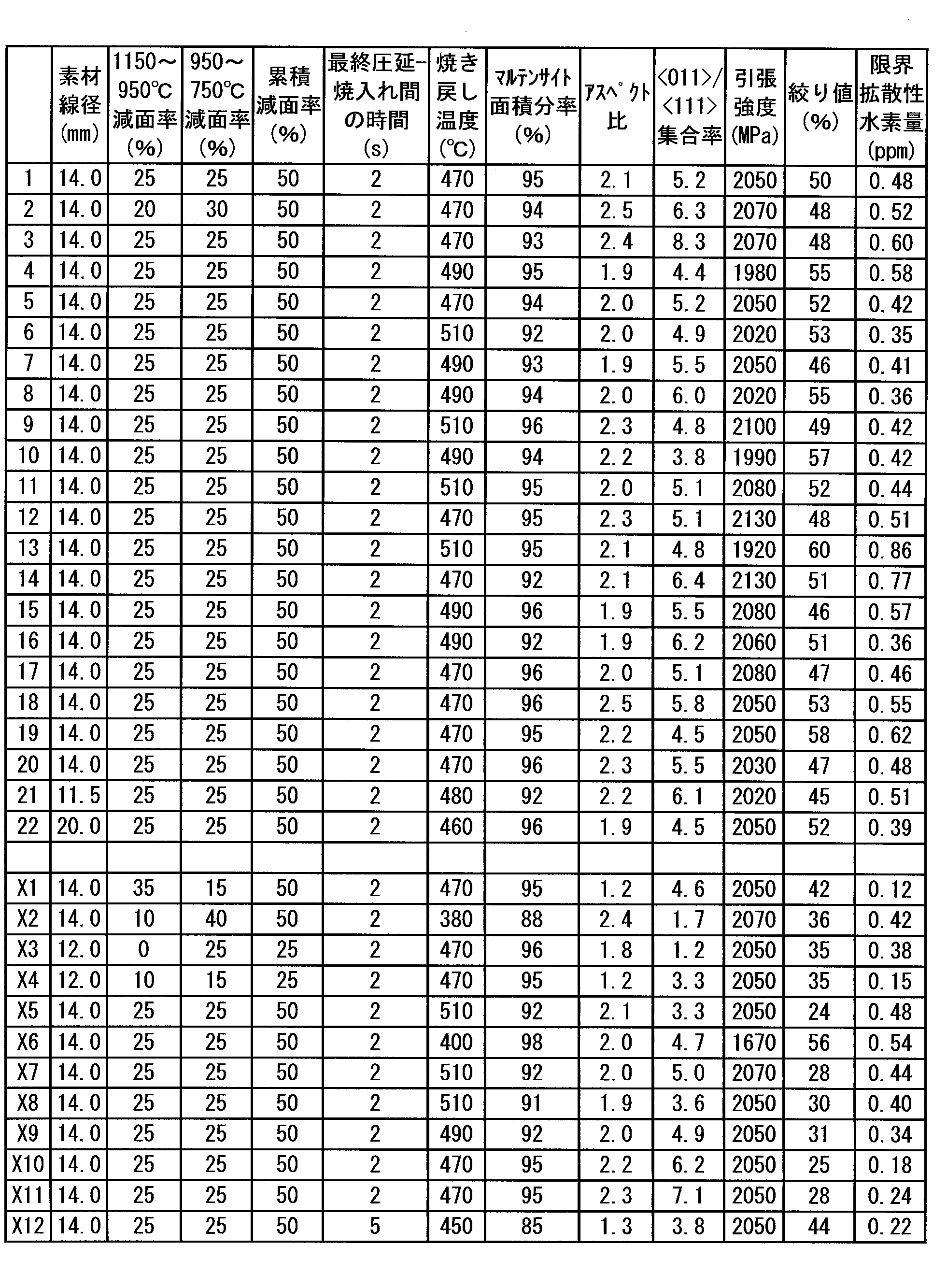
- the round bar steel material which is made of a round bar steel material having the components shown in Table 1 and a diameter of 11.5 to 20.0 mm and subjected to hot rolling-quenching-tempering under the hot rolling conditions shown in Table 2, the microstructure Observation, tensile test, and delayed fracture test, martensite structure fraction (also called martensite fraction), aspect ratio of prior austenite crystal grains, ratio of ⁇ 011> / ⁇ 111> aggregation rate, tensile strength The aperture value and the limit diffusible hydrogen amount were evaluated. In all examples, the quenching conditions were cooling at a cooling rate of 50 ° C./second or more until the surface temperature reached 30 ° C. In Tables 1 and 2, Examples 1 to 19 are examples, and Examples X1 to X11 are comparative examples.
- the martensite fraction was calculated from structural observation with an optical microscope.
- the L cross-section obtained by cutting the round steel bar parallel to the rolling direction was mirror-polished, and then the microstructure was revealed with 3% nital, and the surface layer portion, the radius 1/2 position, And the microstructure of three visual fields and three visual fields in total at three locations in the central part was observed, and the average martensite fraction was calculated.
- the aspect ratio of the prior austenite crystal grains was calculated from structural observation with an optical microscope. For the same L cross-section as above, after the mirror polishing, the prior austenite crystal grains were exposed with a picric acid aqueous solution-based corrosive solution, and five micrographs were taken at a magnification of 400 times at a position of 10% of the diameter from the steel surface. . For these photographs, the aspect ratio was determined from the length in the major axis direction of the prior austenite crystal grains and the length in the direction perpendicular to the major axis direction, as counted by the cutting method. ] / “Crystal grain size (width) in a direction perpendicular to the major axis direction” was calculated.
- the ratio of ⁇ 011> assembly ratio / ⁇ 111> assembly ratio of the martensite texture as viewed from the rolling direction is the same as that of the above L-section microstructure SEM-EBSD (JSM7001-F, EDAX's OIM manufactured by JEOL Ltd.) It was calculated by analyzing with.
- the tensile test was a round bar tensile test according to JIS Z 2201 and 2241.
- the amount of critical diffusible hydrogen was calculated by a delayed fracture test using a hydrogen precharge method.
- hydrogen precharge method for example, hydrogen is charged into a test piece by cathodic hydrogen charging in an aqueous solution containing NH 4 SCN, and then a delayed fracture test is performed in a state where hydrogen is sealed by HCP metal plating of Cd, Zn, etc. It is a method to do.
- hydrogen was precharged and a constant load delayed fracture test was performed with a load 0.3 times the tensile strength (0.3 TS).
- the amount of critical diffusible hydrogen which is the amount of hydrogen, was measured.
- the aspect ratio of the prior austenite crystal grains is 1.5 or more, and the ratio of ⁇ 011> assembly ratio / ⁇ 111> assembly ratio of the martensite texture as viewed from the rolling direction is 3. 0 or more.
- the tensile strength, the drawing value, and the critical diffusible hydrogen amount are compatible at a high level.
- Example X1 since the area reduction rate in the temperature range of 950 ° C. or higher was large and the area reduction rate in the temperature range of 950 to 750 ° C. was small, the aspect ratio of the prior austenite crystal grains was reduced, and the amount of critical diffusible hydrogen was also high. It was low.
- Example X4 the area reduction was small in the temperature range of 950 ° C. or higher and 950 to 750 ° C., the aspect ratio of the prior austenite crystal grains was small, and the aperture value and the amount of critical diffusible hydrogen were low.
- Example X5 and Examples X7 to X11 the aperture value was insufficient.
- the amount of critical diffusible hydrogen was also insufficient.
- Example X5 has a high Si content
- Example X7 has a high C content
- Example X8 has a high Mn content
- Example X9 has a high Cr content
- Example X10 has a high P content
- Example X11 has an S content The amount was high.
- Example X12 the time from the final rolling to quenching was long, the martensite fraction was lowered, and the aspect ratio of the prior austenite crystal grains was insufficient. This is probably because ferrite nucleation progressed from the processed structure before quenching.
- Example X6 the C content was low, and sufficient tensile strength could not be obtained.
- the suspension spring steel of the present disclosure has high tensile strength and excellent delayed fracture resistance and drawing value.
- the steel for suspension springs of the present disclosure is a trace amount even if it does not contain expensive alloy elements, has a tensile strength of 1800 MPa or more, and has an excellent cold workability and delayed fracture resistance, such as an automobile. Industrial effects such as reduction in weight of the suspension spring used in the present invention are extremely remarkable.
Landscapes
- Chemical & Material Sciences (AREA)
- Engineering & Computer Science (AREA)
- Mechanical Engineering (AREA)
- Organic Chemistry (AREA)
- Materials Engineering (AREA)
- Metallurgy (AREA)
- Thermal Sciences (AREA)
- Crystallography & Structural Chemistry (AREA)
- Physics & Mathematics (AREA)
- General Engineering & Computer Science (AREA)
- Manufacturing & Machinery (AREA)
- Heat Treatment Of Steel (AREA)
- Springs (AREA)
Abstract
Description
したがって、高価な合金元素の添加を抑制してまたは要しないで、1800MPa以上の引張強度を有し且つ耐遅れ破壊特性及び冷間加工性に優れた懸架ばね用鋼及びその製造方法が望まれている。
C:0.40~0.70%、
Si:0.80~2.20%、
Mn:0.05~1.50%、
Cr:0.05~1.00%
を含有し、
P:0.020%以下、
S:0.020%以下
に制限し、残部がFe及び不可避的不純物よりなり、
圧延方向に平行な断面において、面積率で金属組織の90%以上が焼戻しマルテンサイトであり、
圧延方向に平行な断面において、表面から直径又は厚さの10%の範囲で、旧オーステナイト結晶粒の長軸方向の長さと前記長軸方向に直交する方向の長さとの比が1.5以上であり、圧延方向から見たマルテンサイト集合組織の<011>集合率/<111>集合率の比が3.0以上である、
ことを特徴とする懸架ばね用鋼。
(2)更に、質量%で、
Mo:0.50%以下、
V:0.50%以下、
Ni:1.00%以下、
Cu:0.50%以下、
B:0.0050%以下
の1種又は2種以上を含有することを特徴とする上記(1)に記載の懸架ばね用鋼。
(3)更に、質量%で、
Al:0.500%以下、
Ti:0.200%以下、
Nb:0.100%以下、
の1種又は2種以上を含有することを特徴とする上記(1)または(2)に記載の懸架ばね用鋼。
(4)引張強度が1800MPa以上、絞り値が40%以上であり、丸棒直径の10%深さまで60°円環ノッチを付けた試験片に引張強度の30%の試験荷重を負荷して測定した限界拡散性水素量が0.30ppm以上であることを特徴とする上記(1)~(3)のいずれかに記載の懸架ばね用鋼。
(5)上記(1)~(4)のいずれかに記載の懸架ばね用鋼を製造する方法であって、
上記(1)~(3)のいずれかに記載の鋼成分を有する線材に、1150℃未満950℃以上の温度域で15%以上30%未満の減面率を与え、次いで、950℃未満750℃以上の温度域で20%以上の減面率及び前記1150℃未満950℃以上の温度域の減面率との累積で40%以上の減面率を与えるように熱間圧延を施すこと、
前記熱間圧延した鋼線を焼入れして、圧延方向に平行な断面において面積率で金属組織の90%以上をマルテンサイトとすること、及び
前記焼入れした鋼線に焼戻し処理を行なうこと、
を含み、
前記熱間圧延の終了から前記焼入れの開始までの時間が3秒以内である、
懸架ばね用鋼の製造方法。
Cは、焼入れ処理及び焼戻し処理によって、懸架ばね用鋼の強度を上昇させるために必要な元素である。懸架ばね用鋼の強度を確保するために、C量は0.40%以上にする必要がある。C量は好ましくは0.45%以上、より好ましくは0.48%以上である。一方、懸架ばね用鋼の靭性を確保するために、C量の上限は0.70%である必要がある。C量は好ましくは0.65%以下、より好ましくは0.60%以下である。
Siは、懸架ばね用鋼の引張強度を上昇させるとともに、特に弾性限を上昇させ、懸架ばねの使用中の形状変化であるヘタリに対する耐性を向上させる、非常に重要な元素である。このような効果を得るために、Si量を0.80%以上とする。さらに、Si添加は焼戻し軟化抵抗を高めるため、特に引張強度向上の観点から、Si量は好ましくは1.20%以上である。一方、鋼材の脆化を抑制するため、Si量の上限を2.20%とする。製鋼・圧延工程での製造性向上の観点から、Si量は好ましくは2.00%以下である。
Mnは、懸架ばね用鋼の脱硫に必要な元素であり、Mn量は0.05%以上である。さらに、Mnは焼入れ時の焼入れ性向上にも有効な元素であり、この効果を得る観点から、Mn量は好ましくは0.20%以上である。一方、成分偏析を抑制してオーステナイト温度域での粒界の脆化を防止する観点から、Mn量の上限は1.50%である。
Crは、懸架ばね用鋼の引張強度上昇及び焼入れ性向上に有効な元素であり、これらの効果を得るために、Cr量を0.05%以上とする。さらに、焼戻し軟化抵抗を高める観点から、Cr量は好ましくは0.15%以上である。一方、オーステナイト温度域への加熱時に未溶解炭化物の残存を抑制し成分の不均一や破壊起点となる粗大炭化物の生成を防止する観点から、Cr量の上限は1.00%である。
Pは、不純物であり、鋼材の脆化を抑制するために、P量を0.020%以下に制限する。
Sは、不純物であり、鋼材の脆化を抑制するために、S量を0.020%以下に制限する。
Moは、微量の添加で焼入れ性の向上に寄与する元素であり、懸架ばね用鋼は、0.05%以上のMoを含有することが好ましい。Moは、炭化物の析出強化による懸架ばね用鋼の強度上昇にも有効な元素であり、この効果を得る観点で、懸架ばね用鋼は、0.10%以上のMo量を含有することがより好ましい。一方で、Moを過剰に添加するとオーステナイト温度域加熱時に未溶解炭化物が増加して鋼材の焼入れ性の低下を招くため、Mo量は好ましくは0.50%以下である。Moは高価な合金元素であることから、Mo量は、コストの観点から、より好ましくは0.45%以下、さらに好ましくは0.20%以下、さらにより好ましくは含まれない。本開示の懸架ばね用鋼は、Moを含まないか極微量で含む場合でも、大きな引張強度と優れた耐遅れ破壊特性及び冷間加工性を有することができる。Moをさらに含有させると、本開示の懸架ばね用鋼は、より良好な特性を得ることができる。
Vは、微量の添加で焼入れ性の向上に寄与する元素であり、懸架ばね用鋼は、0.03%以上のVを含有することが好ましい。Vは、炭化物の析出強化による懸架ばね用鋼の強度上昇にも有効な元素であり、この効果を得る観点で、懸架ばね用鋼は、0.10%以上のVを含有することがより好ましい。一方で、Vを過剰に添加するとオーステナイト温度域加熱時に未溶解炭化物が増加して鋼材の焼入れ性の低下を招くため、V量は好ましくは0.50%以下である。Vは高価な合金元素であることから、コストの観点から、V量は、より好ましくは0.25%以下、さらに好ましくは0.10%以下、さらにより好ましくは含まれない。本開示の懸架ばね用鋼は、Vを含まないか極微量で含む場合でも、大きな引張強度と優れた耐遅れ破壊特性及び冷間加工性を有することができる。Vをさらに含有させると、本開示の懸架ばね用鋼は、より良好な特性を得ることができる。
Niは、懸架ばね用鋼の靭性及び焼入れ性の向上に寄与する元素であり、懸架ばね用鋼は、0.10%以上のNiを含有することが好ましい。Niは、耐食性の向上にも有効な元素であり、この効果を得る観点で、懸架ばね用鋼は、0.15%以上のNi含有することがより好ましい。一方で、上記効果は微量のNi添加で得られ過剰に添加しても上記効果の増加は見込めないことから、Ni量は好ましくは1.00%以下である。Niは高価な合金元素であることから、コストの観点から、Ni量は、より好ましくは0.60%以下、さらに好ましくは0.30%以下、さらにより好ましくは含まれない。本開示の懸架ばね用鋼は、Niを含まないか極微量で含む場合でも、大きな引張強度と優れた耐遅れ破壊特性及び冷間加工性を有することができる。Niをさらに含有させると、本開示の懸架ばね用鋼は、より良好な特性を得ることができる。
Cuは、懸架ばね用鋼の焼入れ性の向上に寄与する元素であり、懸架ばね用鋼は、0.05%以上のCuを含有することが好ましい。Cuは耐食性の向上にも有効な元素であり、この効果を得る観点で、懸架ばね用鋼は、0.10%以上のCuを含有することがより好ましい。一方で、Cuを過剰に添加するとオーステナイト域での圧延割れの原因になり得るため、Cu量は好ましくは0.50%以下、さらに好ましくは0.30%以下である。
Bは、焼入れ性を向上させると同時に、粒界を清浄化して靭性を向上させる元素であり、懸架ばね用鋼は、0.0010%以上のBを含有することが好ましい。ただし、Bを過剰に添加すると鋼材の熱間延性を低下させて製造性を悪化させるため、B量は好ましくは0.0050%以下である。
Alは、脱酸元素であり、懸架ばね用鋼の高清浄度化のために、懸架ばね用鋼は、0.003%以上のAlを含有することが好ましい。また、Alは、AlNなどの析出粒子により熱処理中のオーステナイト結晶粒の粗大化を抑制するのに有効な元素でもあり、この効果を得る観点で、Al量はより好ましくは0.020%以上である。一方、Al量が多すぎると、破壊起点となる粗大な介在物を生成しやすくなるため、Al量は好ましくは0.500%以下である。ただし、本開示の懸架ばね用鋼は、Alを含まないか0.001%以下の不可避不純物レベルの極微量で含む場合でも、大きな引張強度と優れた耐遅れ破壊特性及び冷間加工性とを有することができる。懸架ばね用鋼が0.001%以下のAlを含んだとしても、0.001%以下の不可避不純物レベルでは、脱酸元素としての効果は実質的に得られず、懸架ばね用鋼は、Alを含まない場合と同量の酸素を含有する。
Tiは、TiNなどの析出粒子により熱処理中のオーステナイト結晶粒の粗大化を抑制するのに有効な元素であり、懸架ばね用鋼は、0.002%以上のTiを含有することが好ましい。さらには、B添加の効果を得る目的などで固溶N量を低下させる観点で、Ti量はより好ましくは0.010%以上である。ただし、過剰に添加すると鋼材を脆化させるため、Ti量は好ましくは0.200%以下である。
Nbは、NbNなどの析出粒子により熱処理中のオーステナイト結晶粒の粗大化を抑制するのに有効な元素であり、懸架ばね用鋼は、0.002%以上のNbを含有することが好ましい。さらには、B添加の効果を得る目的などで固溶N量を低下させる観点で、Nb量はより好ましくは0.010%以上である。ただし、過剰に添加すると鋼材を脆化させるため、Nb量は好ましくは0.100%以下である。
{(素材の断面積)-(引張破断部の最小断面積)}/(素材の断面積)×100%
によって算出することができる。断面積とは、引張方向に直交する方向の面積である。
{(圧延前の断面積)-(圧延後の断面積)}/(圧延前の断面積)×100%
によって算出することができる。断面積とは、圧延方向に直交する方向の面積である。

Claims (5)
- 質量%で、
C:0.40~0.70%、
Si:0.80~2.20%、
Mn:0.05~1.50%、
Cr:0.05~1.00%
を含有し、
P:0.020%以下、
S:0.020%以下
に制限し、残部がFe及び不可避的不純物よりなり、
圧延方向に平行な断面において、面積率で金属組織の90%以上が焼戻しマルテンサイトであり、
圧延方向に平行な断面において、表面から直径又は厚さの10%の範囲で、旧オーステナイト結晶粒の長軸方向の長さと前記長軸方向に直交する方向の長さとの比が1.5以上であり、圧延方向から見たマルテンサイト集合組織の<011>集合率/<111>集合率の比が3.0以上である、
ことを特徴とする懸架ばね用鋼。 - 更に、質量%で、
Mo:0.50%以下、
V:0.50%以下、
Ni:1.00%以下、
Cu:0.50%以下、
B:0.0050%以下
の1種又は2種以上を含有することを特徴とする、請求項1に記載の懸架ばね用鋼。 - 更に、質量%で、
Al:0.50%以下、
Ti:0.20%以下、
Nb:0.10%以下、
の1種又は2種以上を含有することを特徴とする、請求項1または2に記載の懸架ばね用鋼。 - 引張強度が1800MPa以上、絞り値が40%以上であり、丸棒直径の10%深さまで60°円環ノッチを付けた試験片に引張強度の30%の試験荷重を負荷して測定した限界拡散性水素量が0.30ppm以上であることを特徴とする、請求項1~3のいずれか一項に記載の懸架ばね用鋼。
- 請求項1~4のいずれか一項に記載の懸架ばね用鋼を製造する方法であって、
請求項1~3のいずれか一項に記載の鋼成分を有する線材に、1150℃未満950℃以上の温度域で15%以上30%未満の減面率を与え、次いで、950℃未満750℃以上の温度域で20%以上の減面率及び前記1150℃未満950℃以上の温度域の減面率との累積で40%以上の減面率を与えるように、熱間圧延を施すこと、
前記熱間圧延した鋼線を焼入れして、圧延方向に平行な断面において面積率で金属組織の90%以上をマルテンサイトとすること、及び
前記焼入れした鋼線に焼戻し処理を行なうこと、
を含み、
前記熱間圧延の終了から前記焼入れの開始までの時間が3秒以内である、
懸架ばね用鋼の製造方法。
Priority Applications (7)
| Application Number | Priority Date | Filing Date | Title |
|---|---|---|---|
| US15/744,394 US20180230566A1 (en) | 2015-07-27 | 2016-07-27 | Spring steel for suspension and method for producing same |
| EP16830562.1A EP3330399B1 (en) | 2015-07-27 | 2016-07-27 | Steel for suspension spring and method for manufacturing same |
| JP2017530905A JP6407436B2 (ja) | 2015-07-27 | 2016-07-27 | 懸架ばね用鋼及びその製造方法 |
| BR112018000278-0A BR112018000278A2 (ja) | 2015-07-27 | 2016-07-27 | Steel for suspension springs, and a manufacturing method for the same |
| KR1020187001798A KR102087525B1 (ko) | 2015-07-27 | 2016-07-27 | 현가 스프링용 강 및 그의 제조 방법 |
| MX2018001142A MX2018001142A (es) | 2015-07-27 | 2016-07-27 | Acero para muelle de suspension y metodo para fabricar el mismo. |
| CN201680038130.1A CN107709597B (zh) | 2015-07-27 | 2016-07-27 | 悬架弹簧用钢及其制造方法 |
Applications Claiming Priority (2)
| Application Number | Priority Date | Filing Date | Title |
|---|---|---|---|
| JP2015-147697 | 2015-07-27 | ||
| JP2015147697 | 2015-07-27 |
Publications (1)
| Publication Number | Publication Date |
|---|---|
| WO2017018457A1 true WO2017018457A1 (ja) | 2017-02-02 |
Family
ID=57884802
Family Applications (1)
| Application Number | Title | Priority Date | Filing Date |
|---|---|---|---|
| PCT/JP2016/072051 Ceased WO2017018457A1 (ja) | 2015-07-27 | 2016-07-27 | 懸架ばね用鋼及びその製造方法 |
Country Status (8)
| Country | Link |
|---|---|
| US (1) | US20180230566A1 (ja) |
| EP (1) | EP3330399B1 (ja) |
| JP (1) | JP6407436B2 (ja) |
| KR (1) | KR102087525B1 (ja) |
| CN (1) | CN107709597B (ja) |
| BR (1) | BR112018000278A2 (ja) |
| MX (1) | MX2018001142A (ja) |
| WO (1) | WO2017018457A1 (ja) |
Cited By (3)
| Publication number | Priority date | Publication date | Assignee | Title |
|---|---|---|---|---|
| CN108179355A (zh) * | 2018-01-31 | 2018-06-19 | 中钢集团郑州金属制品研究院有限公司 | 一种高强度高韧性弹簧钢丝及其制备工艺 |
| WO2018230717A1 (ja) * | 2017-06-15 | 2018-12-20 | 新日鐵住金株式会社 | ばね鋼用圧延線材 |
| WO2024101377A1 (ja) * | 2022-11-08 | 2024-05-16 | 日本発條株式会社 | 鋼線材および鋼線材の製造方法 |
Families Citing this family (9)
| Publication number | Priority date | Publication date | Assignee | Title |
|---|---|---|---|---|
| CN112063816B (zh) * | 2019-06-10 | 2021-11-19 | 育材堂(苏州)材料科技有限公司 | 一种高强度钢的热处理方法和由此获得的产品 |
| PL3783120T3 (pl) * | 2019-08-23 | 2024-02-19 | Vossloh Fastening Systems Gmbh | Drut sprężynowy, zacisk napinający uformowany z niego i sposób wytwarzania takiego drutu sprężynowego |
| CN111519114B (zh) * | 2020-05-14 | 2022-06-21 | 大冶特殊钢有限公司 | 一种弹簧扁钢材料及其制备方法 |
| CN111961966A (zh) * | 2020-07-31 | 2020-11-20 | 南京钢铁股份有限公司 | 一种汽车悬架弹簧钢盘条及其制备方法 |
| KR102492641B1 (ko) * | 2020-12-17 | 2023-01-30 | 주식회사 포스코 | 내피로특성과 질화처리 특성이 향상된 스프링용 선재, 강선, 스프링 및 그 제조 방법 |
| KR102531464B1 (ko) * | 2020-12-18 | 2023-05-12 | 주식회사 포스코 | 초고강도 스프링용 선재, 강선 및 그 제조방법 |
| CN117004888B (zh) * | 2023-08-09 | 2026-01-06 | 天津荣程联合钢铁集团有限公司 | 一种高强度Cr-V-Mo系中碳弹簧钢及其热处理工艺和应用 |
| CN116770191B (zh) * | 2023-08-28 | 2023-10-27 | 张家港荣盛特钢有限公司 | 耐腐蚀疲劳弹簧钢丝、盘条及其生产方法 |
| WO2025210377A1 (en) * | 2024-04-02 | 2025-10-09 | Arcelormittal | Steel for coil springs of automobiles and a method of manufacturing of a coil thereof |
Citations (6)
| Publication number | Priority date | Publication date | Assignee | Title |
|---|---|---|---|---|
| JP2002097551A (ja) * | 2000-09-25 | 2002-04-02 | Nippon Steel Corp | 耐水素疲労特性の優れた高強度ばね用鋼およびその製造方法 |
| JP2005220422A (ja) * | 2004-02-06 | 2005-08-18 | Sumitomo Denko Steel Wire Kk | ばね用鋼線 |
| JP2009256771A (ja) * | 2008-03-27 | 2009-11-05 | Jfe Steel Corp | 耐遅れ破壊特性に優れた高強度ばね用鋼およびその製造方法 |
| JP2011011245A (ja) * | 2009-07-03 | 2011-01-20 | Nippon Steel Corp | 中〜高炭素鋼線材の連続加工熱処理ライン |
| JP2014043612A (ja) * | 2012-08-27 | 2014-03-13 | Nippon Steel & Sumitomo Metal | 耐遅れ破壊特性に優れた高強度鋼材 |
| JP2014122393A (ja) * | 2012-12-21 | 2014-07-03 | Kobe Steel Ltd | 耐水素脆性に優れた高強度ばね用鋼線材およびその製造方法並びに高強度ばね |
Family Cites Families (10)
| Publication number | Priority date | Publication date | Assignee | Title |
|---|---|---|---|---|
| JPH06346146A (ja) | 1993-06-07 | 1994-12-20 | Sumitomo Metal Ind Ltd | 冷間成形コイルばね用線材の製造方法と装置 |
| JPH09310151A (ja) | 1996-05-16 | 1997-12-02 | Kobe Steel Ltd | 冷間加工性に優れたばね用鋼線材 |
| DE19637968C2 (de) * | 1996-09-18 | 2002-05-16 | Univ Freiberg Bergakademie | Verfahren zur hochtemperatur-thermomechanischen Herstellung von Federblättern für Blattfedern und/oder Blattfederlenkern |
| JP4261760B2 (ja) * | 2000-10-10 | 2009-04-30 | 新日本製鐵株式会社 | 耐水素疲労破壊特性に優れた高強度ばね用鋼およびその製造方法 |
| KR100711370B1 (ko) * | 2003-03-28 | 2007-05-02 | 가부시키가이샤 고베 세이코쇼 | 가공성이 우수한 고강도 스프링용 강선 및 고강도 스프링 |
| JP4476863B2 (ja) * | 2005-04-11 | 2010-06-09 | 株式会社神戸製鋼所 | 耐食性に優れた冷間成形ばね用鋼線 |
| JP5653020B2 (ja) * | 2009-09-29 | 2015-01-14 | 中央発條株式会社 | 腐食疲労強度に優れるばね用鋼及びばね |
| CN103290194B (zh) * | 2013-03-19 | 2015-04-29 | 钱江弹簧(北京)有限公司 | 高应力悬架弹簧制作工艺 |
| CN104313483B (zh) * | 2014-10-31 | 2016-09-07 | 武汉钢铁(集团)公司 | 一种高碳冷轧汽车膜片弹簧钢及其生产方法 |
| CN104313472B (zh) * | 2014-10-31 | 2016-06-22 | 武汉钢铁(集团)公司 | 一种高碳热轧汽车膜片弹簧钢及其生产方法 |
-
2016
- 2016-07-27 MX MX2018001142A patent/MX2018001142A/es unknown
- 2016-07-27 WO PCT/JP2016/072051 patent/WO2017018457A1/ja not_active Ceased
- 2016-07-27 US US15/744,394 patent/US20180230566A1/en not_active Abandoned
- 2016-07-27 JP JP2017530905A patent/JP6407436B2/ja active Active
- 2016-07-27 BR BR112018000278-0A patent/BR112018000278A2/ja active Search and Examination
- 2016-07-27 EP EP16830562.1A patent/EP3330399B1/en active Active
- 2016-07-27 CN CN201680038130.1A patent/CN107709597B/zh active Active
- 2016-07-27 KR KR1020187001798A patent/KR102087525B1/ko active Active
Patent Citations (6)
| Publication number | Priority date | Publication date | Assignee | Title |
|---|---|---|---|---|
| JP2002097551A (ja) * | 2000-09-25 | 2002-04-02 | Nippon Steel Corp | 耐水素疲労特性の優れた高強度ばね用鋼およびその製造方法 |
| JP2005220422A (ja) * | 2004-02-06 | 2005-08-18 | Sumitomo Denko Steel Wire Kk | ばね用鋼線 |
| JP2009256771A (ja) * | 2008-03-27 | 2009-11-05 | Jfe Steel Corp | 耐遅れ破壊特性に優れた高強度ばね用鋼およびその製造方法 |
| JP2011011245A (ja) * | 2009-07-03 | 2011-01-20 | Nippon Steel Corp | 中〜高炭素鋼線材の連続加工熱処理ライン |
| JP2014043612A (ja) * | 2012-08-27 | 2014-03-13 | Nippon Steel & Sumitomo Metal | 耐遅れ破壊特性に優れた高強度鋼材 |
| JP2014122393A (ja) * | 2012-12-21 | 2014-07-03 | Kobe Steel Ltd | 耐水素脆性に優れた高強度ばね用鋼線材およびその製造方法並びに高強度ばね |
Cited By (6)
| Publication number | Priority date | Publication date | Assignee | Title |
|---|---|---|---|---|
| WO2018230717A1 (ja) * | 2017-06-15 | 2018-12-20 | 新日鐵住金株式会社 | ばね鋼用圧延線材 |
| JP6447799B1 (ja) * | 2017-06-15 | 2019-01-09 | 新日鐵住金株式会社 | ばね鋼用圧延線材 |
| EP3640357A4 (en) * | 2017-06-15 | 2020-09-30 | Nippon Steel Corporation | ROLLED WIRE FOR SPRING STEEL |
| US11118251B2 (en) | 2017-06-15 | 2021-09-14 | Nippon Steel Corporation | Rolled wire rod for spring steel |
| CN108179355A (zh) * | 2018-01-31 | 2018-06-19 | 中钢集团郑州金属制品研究院有限公司 | 一种高强度高韧性弹簧钢丝及其制备工艺 |
| WO2024101377A1 (ja) * | 2022-11-08 | 2024-05-16 | 日本発條株式会社 | 鋼線材および鋼線材の製造方法 |
Also Published As
| Publication number | Publication date |
|---|---|
| JP6407436B2 (ja) | 2018-10-17 |
| KR20180019212A (ko) | 2018-02-23 |
| JPWO2017018457A1 (ja) | 2018-05-24 |
| US20180230566A1 (en) | 2018-08-16 |
| BR112018000278A2 (ja) | 2018-09-04 |
| MX2018001142A (es) | 2018-04-20 |
| KR102087525B1 (ko) | 2020-03-10 |
| EP3330399A4 (en) | 2019-03-27 |
| CN107709597A (zh) | 2018-02-16 |
| EP3330399A1 (en) | 2018-06-06 |
| CN107709597B (zh) | 2019-08-27 |
| EP3330399B1 (en) | 2020-03-25 |
Similar Documents
| Publication | Publication Date | Title |
|---|---|---|
| JP6407436B2 (ja) | 懸架ばね用鋼及びその製造方法 | |
| CN101321885B (zh) | 高强度弹簧用热处理钢 | |
| JP6306711B2 (ja) | 耐遅れ破壊特性を有するマルテンサイト鋼および製造方法 | |
| US9970072B2 (en) | High-strength spring steel wire with excellent hydrogen embrittlement resistance, manufacturing process therefor, and high-strength spring | |
| JP5520591B2 (ja) | 高疲労強度板ばね用鋼及び板ばね部品 | |
| JP6027302B2 (ja) | 高強度焼戻し省略ばね用鋼 | |
| WO2001079567A1 (fr) | Procede de fabrication d'un boulon a grande resistance a la rupture retardee ainsi qu'au relachement | |
| WO2010055609A1 (ja) | 高強度厚鋼板およびその製造方法 | |
| US11578394B2 (en) | Nickel-containing steel for low temperature | |
| US11371121B2 (en) | Nickel-containing steel for low temperature | |
| JP5167616B2 (ja) | 耐遅れ破壊特性に優れた金属ボルト | |
| JP5679455B2 (ja) | ばね用鋼、ばね用鋼線及びばね | |
| WO2012011469A1 (ja) | 熱間鍛造用圧延棒鋼または線材 | |
| WO2017131077A1 (ja) | ばね鋼 | |
| EP3502292B1 (en) | Hot-rolled steel sheet | |
| JP3918587B2 (ja) | 冷間成形用ばね鋼 | |
| JP7163639B2 (ja) | 鋼棒又は鋼製品と、それらの製造方法 | |
| JP5214292B2 (ja) | 耐水素脆性、腐食疲労強度の優れたばね用鋼及びそれを用いた高強度ばね部品 | |
| US20110253265A1 (en) | Quenched and tempered steel pipe with high fatigue life, and its manufacturing method | |
| JP4657128B2 (ja) | 耐水素脆化特性および靭延性に優れた高強度構造用鋼とその製造方法 | |
| JP4867638B2 (ja) | 耐遅れ破壊特性および耐腐食性に優れた高強度ボルト | |
| JP2005350736A (ja) | 耐食性および疲労特性に優れた高強度ばね用鋼およびその製造方法 | |
| WO2023105852A1 (ja) | 冷間鍛造性及び、耐水素脆化特性又は耐食性と非磁性に優れるステンレス鋼 | |
| JP4332446B2 (ja) | 冷間加工性および耐遅れ破壊特性に優れた高強度鋼、並びに耐遅れ破壊特性に優れた高強度鋼部品 | |
| JP5633426B2 (ja) | 熱処理用鋼材 |
Legal Events
| Date | Code | Title | Description |
|---|---|---|---|
| 121 | Ep: the epo has been informed by wipo that ep was designated in this application |
Ref document number: 16830562 Country of ref document: EP Kind code of ref document: A1 |
|
| ENP | Entry into the national phase |
Ref document number: 2017530905 Country of ref document: JP Kind code of ref document: A |
|
| WWE | Wipo information: entry into national phase |
Ref document number: 15744394 Country of ref document: US |
|
| ENP | Entry into the national phase |
Ref document number: 20187001798 Country of ref document: KR Kind code of ref document: A |
|
| WWE | Wipo information: entry into national phase |
Ref document number: MX/A/2018/001142 Country of ref document: MX |
|
| NENP | Non-entry into the national phase |
Ref country code: DE |
|
| WWE | Wipo information: entry into national phase |
Ref document number: 2016830562 Country of ref document: EP |
|
| REG | Reference to national code |
Ref country code: BR Ref legal event code: B01A Ref document number: 112018000278 Country of ref document: BR |
|
| ENP | Entry into the national phase |
Ref document number: 112018000278 Country of ref document: BR Kind code of ref document: A2 Effective date: 20180105 |