WO2017018490A1 - 車両用発光装置 - Google Patents
車両用発光装置 Download PDFInfo
- Publication number
- WO2017018490A1 WO2017018490A1 PCT/JP2016/072215 JP2016072215W WO2017018490A1 WO 2017018490 A1 WO2017018490 A1 WO 2017018490A1 JP 2016072215 W JP2016072215 W JP 2016072215W WO 2017018490 A1 WO2017018490 A1 WO 2017018490A1
- Authority
- WO
- WIPO (PCT)
- Prior art keywords
- light
- light emitting
- lens
- emitting device
- vehicle
- Prior art date
- Legal status (The legal status is an assumption and is not a legal conclusion. Google has not performed a legal analysis and makes no representation as to the accuracy of the status listed.)
- Ceased
Links
Images


Classifications
-
- F—MECHANICAL ENGINEERING; LIGHTING; HEATING; WEAPONS; BLASTING
- F21—LIGHTING
- F21S—NON-PORTABLE LIGHTING DEVICES; SYSTEMS THEREOF; VEHICLE LIGHTING DEVICES SPECIALLY ADAPTED FOR VEHICLE EXTERIORS
- F21S43/00—Signalling devices specially adapted for vehicle exteriors, e.g. brake lamps, direction indicator lights or reversing lights
- F21S43/10—Signalling devices specially adapted for vehicle exteriors, e.g. brake lamps, direction indicator lights or reversing lights characterised by the light source
- F21S43/13—Signalling devices specially adapted for vehicle exteriors, e.g. brake lamps, direction indicator lights or reversing lights characterised by the light source characterised by the type of light source
- F21S43/14—Light emitting diodes [LED]
-
- B—PERFORMING OPERATIONS; TRANSPORTING
- B60—VEHICLES IN GENERAL
- B60Q—ARRANGEMENT OF SIGNALLING OR LIGHTING DEVICES, THE MOUNTING OR SUPPORTING THEREOF OR CIRCUITS THEREFOR, FOR VEHICLES IN GENERAL
- B60Q1/00—Arrangement of optical signalling or lighting devices, the mounting or supporting thereof or circuits therefor
- B60Q1/26—Arrangement of optical signalling or lighting devices, the mounting or supporting thereof or circuits therefor the devices being primarily intended to indicate the vehicle, or parts thereof, or to give signals, to other traffic
- B60Q1/2619—Arrangement of optical signalling or lighting devices, the mounting or supporting thereof or circuits therefor the devices being primarily intended to indicate the vehicle, or parts thereof, or to give signals, to other traffic built in the vehicle body
- B60Q1/2623—Details of the fastening means
- B60Q1/263—Snap-in fasteners
-
- B—PERFORMING OPERATIONS; TRANSPORTING
- B60—VEHICLES IN GENERAL
- B60Q—ARRANGEMENT OF SIGNALLING OR LIGHTING DEVICES, THE MOUNTING OR SUPPORTING THEREOF OR CIRCUITS THEREFOR, FOR VEHICLES IN GENERAL
- B60Q1/00—Arrangement of optical signalling or lighting devices, the mounting or supporting thereof or circuits therefor
- B60Q1/26—Arrangement of optical signalling or lighting devices, the mounting or supporting thereof or circuits therefor the devices being primarily intended to indicate the vehicle, or parts thereof, or to give signals, to other traffic
- B60Q1/2696—Mounting of devices using LEDs
-
- F—MECHANICAL ENGINEERING; LIGHTING; HEATING; WEAPONS; BLASTING
- F21—LIGHTING
- F21S—NON-PORTABLE LIGHTING DEVICES; SYSTEMS THEREOF; VEHICLE LIGHTING DEVICES SPECIALLY ADAPTED FOR VEHICLE EXTERIORS
- F21S41/00—Illuminating devices specially adapted for vehicle exteriors, e.g. headlamps
- F21S41/10—Illuminating devices specially adapted for vehicle exteriors, e.g. headlamps characterised by the light source
- F21S41/14—Illuminating devices specially adapted for vehicle exteriors, e.g. headlamps characterised by the light source characterised by the type of light source
- F21S41/141—Light emitting diodes [LED]
- F21S41/147—Light emitting diodes [LED] the main emission direction of the LED being angled to the optical axis of the illuminating device
- F21S41/148—Light emitting diodes [LED] the main emission direction of the LED being angled to the optical axis of the illuminating device the main emission direction of the LED being perpendicular to the optical axis
-
- F—MECHANICAL ENGINEERING; LIGHTING; HEATING; WEAPONS; BLASTING
- F21—LIGHTING
- F21S—NON-PORTABLE LIGHTING DEVICES; SYSTEMS THEREOF; VEHICLE LIGHTING DEVICES SPECIALLY ADAPTED FOR VEHICLE EXTERIORS
- F21S41/00—Illuminating devices specially adapted for vehicle exteriors, e.g. headlamps
- F21S41/10—Illuminating devices specially adapted for vehicle exteriors, e.g. headlamps characterised by the light source
- F21S41/14—Illuminating devices specially adapted for vehicle exteriors, e.g. headlamps characterised by the light source characterised by the type of light source
- F21S41/141—Light emitting diodes [LED]
- F21S41/151—Light emitting diodes [LED] arranged in one or more lines
-
- F—MECHANICAL ENGINEERING; LIGHTING; HEATING; WEAPONS; BLASTING
- F21—LIGHTING
- F21S—NON-PORTABLE LIGHTING DEVICES; SYSTEMS THEREOF; VEHICLE LIGHTING DEVICES SPECIALLY ADAPTED FOR VEHICLE EXTERIORS
- F21S41/00—Illuminating devices specially adapted for vehicle exteriors, e.g. headlamps
- F21S41/30—Illuminating devices specially adapted for vehicle exteriors, e.g. headlamps characterised by reflectors
- F21S41/32—Optical layout thereof
- F21S41/36—Combinations of two or more separate reflectors
-
- F—MECHANICAL ENGINEERING; LIGHTING; HEATING; WEAPONS; BLASTING
- F21—LIGHTING
- F21S—NON-PORTABLE LIGHTING DEVICES; SYSTEMS THEREOF; VEHICLE LIGHTING DEVICES SPECIALLY ADAPTED FOR VEHICLE EXTERIORS
- F21S43/00—Signalling devices specially adapted for vehicle exteriors, e.g. brake lamps, direction indicator lights or reversing lights
- F21S43/10—Signalling devices specially adapted for vehicle exteriors, e.g. brake lamps, direction indicator lights or reversing lights characterised by the light source
- F21S43/13—Signalling devices specially adapted for vehicle exteriors, e.g. brake lamps, direction indicator lights or reversing lights characterised by the light source characterised by the type of light source
- F21S43/15—Strips of light sources
-
- F—MECHANICAL ENGINEERING; LIGHTING; HEATING; WEAPONS; BLASTING
- F21—LIGHTING
- F21S—NON-PORTABLE LIGHTING DEVICES; SYSTEMS THEREOF; VEHICLE LIGHTING DEVICES SPECIALLY ADAPTED FOR VEHICLE EXTERIORS
- F21S43/00—Signalling devices specially adapted for vehicle exteriors, e.g. brake lamps, direction indicator lights or reversing lights
- F21S43/10—Signalling devices specially adapted for vehicle exteriors, e.g. brake lamps, direction indicator lights or reversing lights characterised by the light source
- F21S43/19—Attachment of light sources or lamp holders
-
- F—MECHANICAL ENGINEERING; LIGHTING; HEATING; WEAPONS; BLASTING
- F21—LIGHTING
- F21S—NON-PORTABLE LIGHTING DEVICES; SYSTEMS THEREOF; VEHICLE LIGHTING DEVICES SPECIALLY ADAPTED FOR VEHICLE EXTERIORS
- F21S43/00—Signalling devices specially adapted for vehicle exteriors, e.g. brake lamps, direction indicator lights or reversing lights
- F21S43/20—Signalling devices specially adapted for vehicle exteriors, e.g. brake lamps, direction indicator lights or reversing lights characterised by refractors, transparent cover plates, light guides or filters
- F21S43/26—Refractors, transparent cover plates, light guides or filters not provided in groups F21S43/235 - F21S43/255
-
- F—MECHANICAL ENGINEERING; LIGHTING; HEATING; WEAPONS; BLASTING
- F21—LIGHTING
- F21S—NON-PORTABLE LIGHTING DEVICES; SYSTEMS THEREOF; VEHICLE LIGHTING DEVICES SPECIALLY ADAPTED FOR VEHICLE EXTERIORS
- F21S43/00—Signalling devices specially adapted for vehicle exteriors, e.g. brake lamps, direction indicator lights or reversing lights
- F21S43/30—Signalling devices specially adapted for vehicle exteriors, e.g. brake lamps, direction indicator lights or reversing lights characterised by reflectors
- F21S43/31—Optical layout thereof
-
- F—MECHANICAL ENGINEERING; LIGHTING; HEATING; WEAPONS; BLASTING
- F21—LIGHTING
- F21S—NON-PORTABLE LIGHTING DEVICES; SYSTEMS THEREOF; VEHICLE LIGHTING DEVICES SPECIALLY ADAPTED FOR VEHICLE EXTERIORS
- F21S43/00—Signalling devices specially adapted for vehicle exteriors, e.g. brake lamps, direction indicator lights or reversing lights
- F21S43/40—Signalling devices specially adapted for vehicle exteriors, e.g. brake lamps, direction indicator lights or reversing lights characterised by the combination of reflectors and refractors
-
- F—MECHANICAL ENGINEERING; LIGHTING; HEATING; WEAPONS; BLASTING
- F21—LIGHTING
- F21V—FUNCTIONAL FEATURES OR DETAILS OF LIGHTING DEVICES OR SYSTEMS THEREOF; STRUCTURAL COMBINATIONS OF LIGHTING DEVICES WITH OTHER ARTICLES, NOT OTHERWISE PROVIDED FOR
- F21V5/00—Refractors for light sources
-
- F—MECHANICAL ENGINEERING; LIGHTING; HEATING; WEAPONS; BLASTING
- F21—LIGHTING
- F21Y—INDEXING SCHEME ASSOCIATED WITH SUBCLASSES F21K, F21L, F21S and F21V, RELATING TO THE FORM OR THE KIND OF THE LIGHT SOURCES OR OF THE COLOUR OF THE LIGHT EMITTED
- F21Y2103/00—Elongate light sources, e.g. fluorescent tubes
- F21Y2103/10—Elongate light sources, e.g. fluorescent tubes comprising a linear array of point-like light-generating elements
-
- F—MECHANICAL ENGINEERING; LIGHTING; HEATING; WEAPONS; BLASTING
- F21—LIGHTING
- F21Y—INDEXING SCHEME ASSOCIATED WITH SUBCLASSES F21K, F21L, F21S and F21V, RELATING TO THE FORM OR THE KIND OF THE LIGHT SOURCES OR OF THE COLOUR OF THE LIGHT EMITTED
- F21Y2115/00—Light-generating elements of semiconductor light sources
- F21Y2115/10—Light-emitting diodes [LED]
Definitions
- the present invention relates to a light emitting device for a vehicle, and more particularly to a light emitting device for a vehicle including a plurality of light sources.
- Some vehicle light-emitting devices include a plurality of light sources.
- various lighting effects may be produced by simultaneously or sequentially illuminating a plurality of light sources.
- the present invention has been made in view of the above problems, and an object of the present invention is to provide a vehicular light emitting device capable of producing an effect so that there are more light sources than the actual number of light sources and reducing unevenness in luminance. There is.
- the problem is that a plurality of light emitting units including a light source and a lens that diffuses and emits light incident from the light source are arranged side by side, and one or more luminance peak values are also present between the plurality of light emitting units. This is solved by the existing vehicle light emitting device.
- the above vehicle light-emitting device it is possible to produce more light sources than the actual number of light sources by having at least one luminance peak between a plurality of light-emitting units each having a light source. And uneven brightness can be reduced.
- the light emitted from the lens of the light-emitting unit has a plurality of luminance peaks with respect to a light spreading direction, and a plurality of light emitted from the plurality of light-emitting units.
- the arrangement intervals of the plurality of light emitting units may be set so that luminance peaks are arranged at substantially equal intervals.
- the luminance peaks of the light emitted from the plurality of light emitting units are substantially equidistant, so that the luminance unevenness can be further reduced.
- the vehicle light-emitting device may include a holding unit that holds the plurality of light-emitting units, and the holding unit may include a reflecting unit that reflects light emitted from the lens toward a light-emitting surface. Thereby, the irradiation direction of light can be adjusted.
- the reflecting portion may be formed with a convex portion at a position facing the light source. Thereby, the reflection direction of the light in a reflection part can be adjusted, and also brightness nonuniformity can be reduced.
- the holding portion may be formed with a recess between regions where the plurality of light emitting units are held.
- the lens may have a locking claw portion at both ends, and may be snap-fixed to the holding portion by the locking claw portion. Thereby, a lens can be stably attached to a holding part.
- the lens may be provided with a rib for restricting rotation with respect to the holding portion.
- the lens may have a notch formed at a position facing the light source. Thereby, the light incident on the lens can be refracted in the diffusing direction.
- the lens may include a light source introduction portion provided on both sides of the notch and protruding toward the light source.
- the luminance peaks of light emitted from a plurality of light emitting units are substantially equally spaced, so that the luminance unevenness can be further reduced.
- the direction of light irradiation can be adjusted.
- light can be prevented from diffusing to the cover side.
- the rotation of the lens with respect to the holding portion is restricted, the light irradiation direction can be stabilized.
- light incident on a lens can be refracted in a diffusing direction.
- the positioning accuracy between the light source and the lens can be improved.
- FIG. 8 is a sectional view taken along line VII-VII in FIG. 7.
- the structural example of the lens at the time of providing a rotation control mechanism is shown, (A) is a top view of the light emission unit containing a lens, (B) is a side view of (A). It is a figure explaining the shape of the light emission unit group which connected the several light emission unit. It is a top view of the light-emitting device for vehicles concerning a 3rd embodiment. It is XI-XI sectional drawing of FIG. It is a figure which shows the characteristic of the luminance peak of the light emission unit which concerns on 3rd Embodiment. It is a figure which shows the characteristic of the luminance peak of the several light emission unit by which the arrangement
- a plurality of light emitting units including a light source and a lens that diffuses and emits light incident from the light source are arranged side by side, and one luminance peak value is also present between the plurality of light emitting units.
- the present invention relates to an invention of a light emitting device for vehicles that exists as described above.
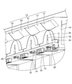
- FIG. 1 is a plan view of a light emitting device 1 for a vehicle according to the first embodiment.
- 2 is a cross-sectional view taken along the line II-II in FIG.
- FIG. 3 is a perspective view of the vehicle light emitting device 1 with the cover 50 removed.
- the lens 30 includes a lens body portion 31, a notch portion 32, a light source introduction portion 33, and an attachment structure portion 34.
- the notch 32 is provided at a position in the center of the lens body 31 and facing the LED unit 20.
- the light source introduction part 33 projects toward the LED part 20 on the rear side of the notch part 32 and introduces incident light from the LED part 20.
- the attachment structure portion 34 is a portion that protrudes outward from both sides of the lens main body portion 31 and attaches the lens 30 to the holder 10.
- a locking claw portion 35 is provided at the rear side end portion of the attachment structure portion 34, and the lens 30 is snap-fit fixed to the holder 10 by the locking claw portion 35.
- the curvature of the notch 32 is larger than the curvature of the front edge of the lens body 31 (for example, the average curvature).
- the curvature of the front edge part of the lens main-body part 31 may be constant, and may not be constant. When it is not constant, for example, the curvature at the center of the front edge may be made smaller than the curvature outside the center.
- the LED part 20 is each arrange
- the light emitting unit 100 is used.
- the series direction is a direction in which the central axis of the lens 30 and the optical axis of the LED unit 20 are parallel (including coincidence).
- the light emitting unit 100 can be thinned by configuring the light emitting unit 100 by arranging the LED unit 20 and the lens 30 in series. By mounting such a thin light-emitting unit 100, the vehicle light-emitting device 1 can be thinned, so that the degree of freedom of installation in the vehicle can be increased.
- the vehicle light-emitting device 1 includes a plurality of light-emitting units 100.
- the plurality of light emitting units 100 are arranged in parallel with the longitudinal direction of the window portion 51.
- the light emitting unit 100 adjacent to the light emitting unit 100 is provided with a convex portion 12 at a position facing the light emitting unit 100 (that is, the LED unit 20) in the reflecting portion 11.
- a plane portion 13 is provided between the positions facing each other (that is, between the convex portion 12 and the convex portion 12).
- the cover 50 has a shape inclined toward the lens 30 from the rear to the front of the lens 30.
- the cover 50 and the lens 30 are closest to each other at the front end portion of the lens 30.
- emitted from the front edge part of the lens 30 reflects in the cover 50, and returns to the back side rather than the window part 51.
- FIG. Thereby, it can suppress that the brightness
- the window part 51 side of the light-emitting device 1 for vehicles be a light emission surface side, and let the opposite side be a back surface side.
- the lens fixing region 18 of the holder 10 has an insertion hole 14 through which the light source introduction portion 33 of the lens 30 is inserted, and a rear end portion (locking claw) of the mounting structure portion 34 of the lens 30. Insertion holes 15 through which the portion 35 is inserted are provided.
- FIG. 5 shows luminance characteristics when a plurality of light emitting units 100 are arranged at a predetermined arrangement interval (D).
- FIG. 5 shows the relationship between the position on the light emitting surface on the front side of the plurality of light emitting units 100 and the luminance.
- the luminance peaks on the light emitting surface can be made substantially equal.
- a peak also exists between the positions facing the light emitting units 100 on the light emitting surface.
- luminance unevenness can be further reduced by setting the luminance peaks at substantially equal intervals.
- FIG. 6 is a plan view of the vehicle light emitting device 1A according to the second embodiment.
- 7 is a sectional view taken along line VII-VII in FIG.
- the light emitting unit 100 mounted on the vehicle light emitting device 1A according to the second embodiment is the same as that of the first embodiment, and thus the description thereof is omitted. In the following, differences from the first embodiment will be mainly described.
- the structure of the cover 50A and the holder 10A is different from that of the vehicle light emitting device 1 according to the first embodiment. That is, as shown in FIG. 7, in the second embodiment, the light emitting unit 100 and the window portion 51A of the cover 50A are disposed in series, and the holder 10A is not provided with the reflection portion forming region 19. This is different from the first embodiment. Furthermore, in the second embodiment, the bowl-shaped recess 60 is formed on the light emitting surface side of the base (holder base region 16A) of the holder 10A and on the surface between the adjacent light emitting units 100. This is different from the first embodiment. The recess 60 is formed so that the width gradually decreases from the front end of the holder base region 16A to the center position of the lens 30.
- FIG. 8 shows a configuration example of the lens 30 when the lens 30 is provided with a rotation restricting mechanism for the holder 10.
- 8A shows a plan view of the light emitting unit 100 including the lens 30 fixed to the holder 10
- FIG. 8B shows a side view of FIG. 8A.
- ribs 36 projecting vertically from the attachment structure 34 are provided on both surfaces of the attachment structure 34 of the lens 30 of the light emitting unit 100.
- the rib 36 functions to regulate the swinging motion of the lens 30 relative to the holder 10 by the rib 36 of the lens 30 abutting against the lens fixing region 18 of the holder 10.
- the above swinging motion refers to a rotational motion in which the front end portion of the lens 30 approaches or moves away from the holder base region 16.
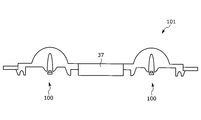
- FIG. 9 An example of a structure in which a single light emitting unit 100 is attached to the holder 10 has been described. However, as illustrated in FIG. 9, a light emitting unit group 101 in which a plurality of light emitting units 100 are connected by a connecting portion 37 is provided. You may make it attach to the holder 10.
- FIG. 9 a light emitting unit group 101 in which a plurality of light emitting units 100 are connected by a connecting portion 37 is provided. You may make it attach to the holder 10.
- FIG. 10 is a plan view of the vehicle light emitting device 1B according to the third embodiment
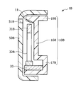
- FIG. 11 is a sectional view taken along line XI-XI in FIG.
- the vehicular light emitting device 1B mainly includes a cover 50B, an LED unit 20 serving as a light source, a lens 30B that diffuses and emits light incident from the LED unit 20, A holder 10B (holding unit) that holds the LED unit 20, the lens 30B, and the like is provided. Further, the holder 10B is provided with a reflecting portion 11 having a mirror finish. The reflection unit 11 reflects the refracted light from the lens 30 ⁇ / b> B toward the window 51 ⁇ / b> B (light emitting surface) of the cover 50.
- the lens 30 ⁇ / b> B includes a lens main body 31 ⁇ / b> B and a notch 32 ⁇ / b> B provided at the center of the lens main body 31 ⁇ / b> B and facing the LED unit 20.
- the LED unit 20 arranged in series with the lens 30B is collectively referred to as a light emitting unit 100B.
- the cover 50B has a U-shape, and the light emitting surface forming surface provided with the window 51B in the cover 50B and the lens 30B are substantially parallel to each other. Further, the length of the light emitting surface forming surface in the front-rear direction (length in the direction perpendicular to the arrangement direction of the light emitting units 100B) is longer than that in the first embodiment.
- the window 51B side of the vehicle light emitting device 1B is the light emitting surface side, and the opposite side is the back surface side.
- the holder 10 includes an LED attachment region 17B, a holder base region 16B, and a reflection portion formation region 19B.
- the LED attachment region 17B is a substantially U-shaped part to which the LED unit 20 is attached and fixed.
- the holder base region 16B is a portion that supports the lens 30B and extends from the LED attachment region 17B substantially in parallel with the lens 30B.
- the reflection portion forming region 19B is a portion that extends from the holder base region 16B to the light emitting surface side, and is a portion where the reflecting portion 11 is provided on the inclined surface that is on the light emitting surface side and faces the lens 30B.
- the angle (slope) of the reflecting surface may be set so that the intensity of the reflected light from the lens 30B to the window 51B is maximized.
- control circuit (not shown) is connected to the LED unit 20, and the light emission timing, the light emission time, and the like of each of the plurality of LED units 20 are controlled by the control circuit.
- the lens 30B mounted on the vehicle light emitting device 1B according to the third embodiment is the same as the lens 30 mounted on the vehicle light emitting device 1 according to the first embodiment.
- the lens body 31 (31B) and the notch 32 (32B) are different in the R shape. That is, in the third embodiment, the curvature of the lens body 31B is larger than the curvature of the lens body 31 in the first embodiment. Moreover, in 3rd Embodiment, the curvature of the notch part 32B is smaller than the curvature of the notch part 32 in 1st Embodiment.
- the diffusion mode of light from the lens can be adjusted and the luminance pattern can be changed.
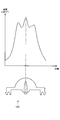
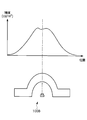
- FIG. 12 shows the luminance characteristics of a single light emitting unit 100B according to the third embodiment.
- FIG. 12 shows the relationship between the position of the light emitting surface on the front side of the single light emitting unit 100B (that is, the position in the width direction of the light emitting surface) and the luminance.
- a gentle luminance peak is present at a position passing from the LED unit 20 through the center of the notch 32 compared to the light emitting unit 100 according to the first embodiment.
- the lens 30B according to the third embodiment emits diffused light with reduced luminance unevenness as compared with the lens 30 according to the first embodiment.
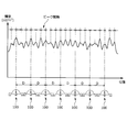
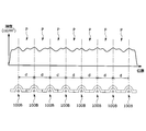
- FIG. 13 shows luminance characteristics when a plurality of light emitting units 100B according to the third embodiment are arranged at a predetermined arrangement interval (d).
- FIG. 13 shows the relationship between the light emitting surface position on the front side of the plurality of light emitting units 100B (that is, the position in the width direction of the light emitting surface) and the luminance.
- a luminance peak also exists between the positions facing the light emitting units 100B.
- luminance unevenness on the light emitting surface can be reduced.
- the diffusion mode of the light from the lens changes by changing the R shape of the lens that diffuses the light incident from the LED unit.
- the light emitting unit is downsized by making the curvature of the outer periphery of the lens smaller than that of the lens in the third embodiment. This makes it possible to reduce the size of the vehicle light emitting device on which the light emitting unit is mounted. In this way, by setting the R shape of the lens, the vehicle light emitting device in which unevenness in luminance is suppressed can be made to correspond to the size of the space required by the vehicle.
- the vehicle light-emitting device according to the first to third embodiments according to the present invention has been mainly described.
- said embodiment is only an example for making an understanding of this invention easy, and does not limit this invention.
- the present invention can be changed and improved without departing from the gist thereof, and the present invention includes the equivalents thereof.
Landscapes
- Engineering & Computer Science (AREA)
- General Engineering & Computer Science (AREA)
- Physics & Mathematics (AREA)
- Microelectronics & Electronic Packaging (AREA)
- Optics & Photonics (AREA)
- Mechanical Engineering (AREA)
- Non-Portable Lighting Devices Or Systems Thereof (AREA)
- Securing Globes, Refractors, Reflectors Or The Like (AREA)
Priority Applications (4)
| Application Number | Priority Date | Filing Date | Title |
|---|---|---|---|
| US15/747,350 US10654405B2 (en) | 2015-07-29 | 2016-07-28 | Vehicular light-emitting device |
| EP16830595.1A EP3330595B1 (de) | 2015-07-29 | 2016-07-28 | Lichtemittierende vorrichtung für ein fahrzeug |
| CN201680037234.0A CN107923588B (zh) | 2015-07-29 | 2016-07-28 | 车用发光装置 |
| US16/863,021 US11320109B2 (en) | 2015-07-29 | 2020-04-30 | Vehicular light-emitting device |
Applications Claiming Priority (2)
| Application Number | Priority Date | Filing Date | Title |
|---|---|---|---|
| JP2015150057A JP6575204B2 (ja) | 2015-07-29 | 2015-07-29 | 車両用発光装置 |
| JP2015-150057 | 2015-07-29 |
Related Child Applications (2)
| Application Number | Title | Priority Date | Filing Date |
|---|---|---|---|
| US15/747,350 A-371-Of-International US10654405B2 (en) | 2015-07-29 | 2016-07-28 | Vehicular light-emitting device |
| US16/863,021 Continuation US11320109B2 (en) | 2015-07-29 | 2020-04-30 | Vehicular light-emitting device |
Publications (1)
| Publication Number | Publication Date |
|---|---|
| WO2017018490A1 true WO2017018490A1 (ja) | 2017-02-02 |
Family
ID=57884404
Family Applications (1)
| Application Number | Title | Priority Date | Filing Date |
|---|---|---|---|
| PCT/JP2016/072215 Ceased WO2017018490A1 (ja) | 2015-07-29 | 2016-07-28 | 車両用発光装置 |
Country Status (5)
| Country | Link |
|---|---|
| US (2) | US10654405B2 (de) |
| EP (1) | EP3330595B1 (de) |
| JP (1) | JP6575204B2 (de) |
| CN (1) | CN107923588B (de) |
| WO (1) | WO2017018490A1 (de) |
Families Citing this family (3)
| Publication number | Priority date | Publication date | Assignee | Title |
|---|---|---|---|---|
| EP3559549B1 (de) * | 2016-12-22 | 2025-05-28 | Flex-N-Gate Advanced Product Development, LLC | Homogene led-fahrzeuglampe |
| EP3878690A1 (de) * | 2020-03-12 | 2021-09-15 | ZKW Group GmbH | Kraftfahrzeug |
| JP2023008845A (ja) * | 2021-07-06 | 2023-01-19 | テイ・エス テック株式会社 | 車両用内装品の照明装置 |
Citations (6)
| Publication number | Priority date | Publication date | Assignee | Title |
|---|---|---|---|---|
| JPH0440352U (de) * | 1990-07-30 | 1992-04-06 | ||
| JPH1184490A (ja) * | 1997-09-02 | 1999-03-26 | Canon Inc | 閃光装置及び該閃光装置を有するカメラ |
| JP2003059312A (ja) * | 2001-08-15 | 2003-02-28 | Koito Mfg Co Ltd | 車両用灯具 |
| JP2003086007A (ja) * | 2001-09-10 | 2003-03-20 | Oshima Denki Seisakusho:Kk | 車両用ランプ |
| JP2012145829A (ja) * | 2011-01-13 | 2012-08-02 | Sharp Corp | 発光装置および照明装置 |
| JP2015002032A (ja) * | 2013-06-14 | 2015-01-05 | 株式会社朝日ラバー | 透光防水カバーレンズ |
Family Cites Families (19)
| Publication number | Priority date | Publication date | Assignee | Title |
|---|---|---|---|---|
| JP2003059313A (ja) * | 2001-08-15 | 2003-02-28 | Koito Mfg Co Ltd | 車両用灯具 |
| JP3953764B2 (ja) | 2001-09-20 | 2007-08-08 | 株式会社小糸製作所 | 車両用灯具 |
| JP4027688B2 (ja) * | 2002-03-15 | 2007-12-26 | 株式会社小糸製作所 | 車両用灯具 |
| US7237925B2 (en) * | 2004-02-18 | 2007-07-03 | Lumination Llc | Lighting apparatus for creating a substantially homogenous lit appearance |
| US20060044806A1 (en) * | 2004-08-25 | 2006-03-02 | Abramov Vladimir S | Light emitting diode system packages |
| US7275849B2 (en) * | 2005-02-25 | 2007-10-02 | Visteon Global Technologies, Inc. | LED replacement bulb |
| GB2464102A (en) * | 2008-10-01 | 2010-04-07 | Optovate Ltd | Illumination apparatus comprising multiple monolithic subarrays |
| US8083380B2 (en) * | 2009-04-17 | 2011-12-27 | Mig Technology Inc. | Integrated structure for optical refractor |
| US7959322B2 (en) * | 2009-04-24 | 2011-06-14 | Whelen Engineering Company, Inc. | Optical system for LED array |
| US8493516B2 (en) * | 2009-06-15 | 2013-07-23 | Sharp Kabushiki Kaisha | Light-emitting module, illumination device, display device, and television receiver |
| JP2012017063A (ja) | 2010-07-09 | 2012-01-26 | Toyota Boshoku Corp | 車両用照明装置 |
| KR101509876B1 (ko) * | 2010-12-01 | 2015-04-06 | 나럭스 컴퍼니 리미티드 | 광학 소자 및 그 광학 소자를 사용한 조명 장치 |
| JP2012243493A (ja) * | 2011-05-18 | 2012-12-10 | Stanley Electric Co Ltd | 車両用信号灯 |
| EP4242516B1 (de) * | 2011-12-02 | 2026-02-25 | Seoul Semiconductor Co., Ltd. | Lichtemittierendes modul und linse |
| US9194566B2 (en) * | 2012-06-08 | 2015-11-24 | Lg Innotek Co., Ltd. | Lamp unit and vehicle lamp apparatus using the same |
| KR102024291B1 (ko) * | 2012-12-18 | 2019-09-23 | 엘지이노텍 주식회사 | 램프 유닛 및 그를 이용한 차량 램프 장치 |
| KR101490347B1 (ko) * | 2013-04-16 | 2015-02-11 | 한국광기술원 | 조명 렌즈 모듈 |
| WO2015004910A1 (ja) | 2013-07-10 | 2015-01-15 | パナソニックIpマネジメント株式会社 | 照明装置およびその照明装置を搭載した自動車 |
| DE102013110344B4 (de) | 2013-09-19 | 2022-09-01 | HELLA GmbH & Co. KGaA | Beleuchtungsvorrichtung für Fahrzeuge zur Erzeugung von Schlusslicht- und Nebelschlusslichtfunktionen |
-
2015
- 2015-07-29 JP JP2015150057A patent/JP6575204B2/ja active Active
-
2016
- 2016-07-28 WO PCT/JP2016/072215 patent/WO2017018490A1/ja not_active Ceased
- 2016-07-28 CN CN201680037234.0A patent/CN107923588B/zh active Active
- 2016-07-28 US US15/747,350 patent/US10654405B2/en active Active
- 2016-07-28 EP EP16830595.1A patent/EP3330595B1/de not_active Not-in-force
-
2020
- 2020-04-30 US US16/863,021 patent/US11320109B2/en active Active
Patent Citations (6)
| Publication number | Priority date | Publication date | Assignee | Title |
|---|---|---|---|---|
| JPH0440352U (de) * | 1990-07-30 | 1992-04-06 | ||
| JPH1184490A (ja) * | 1997-09-02 | 1999-03-26 | Canon Inc | 閃光装置及び該閃光装置を有するカメラ |
| JP2003059312A (ja) * | 2001-08-15 | 2003-02-28 | Koito Mfg Co Ltd | 車両用灯具 |
| JP2003086007A (ja) * | 2001-09-10 | 2003-03-20 | Oshima Denki Seisakusho:Kk | 車両用ランプ |
| JP2012145829A (ja) * | 2011-01-13 | 2012-08-02 | Sharp Corp | 発光装置および照明装置 |
| JP2015002032A (ja) * | 2013-06-14 | 2015-01-05 | 株式会社朝日ラバー | 透光防水カバーレンズ |
Non-Patent Citations (1)
| Title |
|---|
| See also references of EP3330595A4 * |
Also Published As
| Publication number | Publication date |
|---|---|
| EP3330595A1 (de) | 2018-06-06 |
| JP2017033677A (ja) | 2017-02-09 |
| US20200326050A1 (en) | 2020-10-15 |
| CN107923588A (zh) | 2018-04-17 |
| EP3330595B1 (de) | 2021-11-17 |
| CN107923588B (zh) | 2020-09-29 |
| US10654405B2 (en) | 2020-05-19 |
| JP6575204B2 (ja) | 2019-09-18 |
| US11320109B2 (en) | 2022-05-03 |
| EP3330595A4 (de) | 2018-07-25 |
| US20180215310A1 (en) | 2018-08-02 |
Similar Documents
| Publication | Publication Date | Title |
|---|---|---|
| CN101382247B (zh) | 车灯单元 | |
| JP6036493B2 (ja) | 線状照明装置 | |
| JP5675465B2 (ja) | 車両用灯具 | |
| CN106662314A (zh) | 灯具单元及车辆用前照灯 | |
| EP2620695A2 (de) | Fahrzeugscheinwerfer | |
| JP5266034B2 (ja) | 車両用灯具 | |
| CN102691960A (zh) | 机动车照明装置以及具有这种照明装置的机动车大灯 | |
| US11320109B2 (en) | Vehicular light-emitting device | |
| JP5987681B2 (ja) | 線状照明装置 | |
| JP2019197743A (ja) | 車両用発光装置 | |
| JP2019033013A (ja) | 光源ユニット及び照明器具 | |
| JP7140998B2 (ja) | 車両用発光装置 | |
| US12498096B2 (en) | Vehicle lamp | |
| JP2013168269A (ja) | 車両用灯具 | |
| JP2011159554A (ja) | 車両用灯具 | |
| JP2021048015A (ja) | 車両用灯具 | |
| JP6459252B2 (ja) | 車両用灯具 | |
| CN114008383B (zh) | 车辆照明设备 | |
| JP2017211628A (ja) | レンズ及び該レンズを備える車両用灯具構造 | |
| JP2010040485A (ja) | 車輌用灯具 | |
| JP2016021410A (ja) | 車両用灯具 | |
| TW201631279A (zh) | 車燈 | |
| US20190011094A1 (en) | Lens with expanded reflecting surface | |
| JP6292369B2 (ja) | 自動車室内灯用照明装置 | |
| JP2014143057A (ja) | 投影レンズおよび灯具ユニット |
Legal Events
| Date | Code | Title | Description |
|---|---|---|---|
| 121 | Ep: the epo has been informed by wipo that ep was designated in this application |
Ref document number: 16830595 Country of ref document: EP Kind code of ref document: A1 |
|
| WWE | Wipo information: entry into national phase |
Ref document number: 15747350 Country of ref document: US |
|
| NENP | Non-entry into the national phase |
Ref country code: DE |
|
| WWE | Wipo information: entry into national phase |
Ref document number: 2016830595 Country of ref document: EP |