WO2017020964A1 - Ensemble de montage amélioré pour une utilisation dans un appareil de cuisson - Google Patents
Ensemble de montage amélioré pour une utilisation dans un appareil de cuisson Download PDFInfo
- Publication number
- WO2017020964A1 WO2017020964A1 PCT/EP2015/068176 EP2015068176W WO2017020964A1 WO 2017020964 A1 WO2017020964 A1 WO 2017020964A1 EP 2015068176 W EP2015068176 W EP 2015068176W WO 2017020964 A1 WO2017020964 A1 WO 2017020964A1
- Authority
- WO
- WIPO (PCT)
- Prior art keywords
- support
- mounting assembly
- cooking appliance
- casing
- functional components
- Prior art date
- Legal status (The legal status is an assumption and is not a legal conclusion. Google has not performed a legal analysis and makes no representation as to the accuracy of the status listed.)
- Ceased
Links
Images



Classifications
-
- H—ELECTRICITY
- H05—ELECTRIC TECHNIQUES NOT OTHERWISE PROVIDED FOR
- H05B—ELECTRIC HEATING; ELECTRIC LIGHT SOURCES NOT OTHERWISE PROVIDED FOR; CIRCUIT ARRANGEMENTS FOR ELECTRIC LIGHT SOURCES, IN GENERAL
- H05B6/00—Heating by electric, magnetic or electromagnetic fields
- H05B6/02—Induction heating
- H05B6/10—Induction heating apparatus, other than furnaces, for specific applications
- H05B6/12—Cooking devices
- H05B6/1209—Cooking devices induction cooking plates or the like and devices to be used in combination with them
- H05B6/1245—Cooking devices induction cooking plates or the like and devices to be used in combination with them with special coil arrangements
-
- F—MECHANICAL ENGINEERING; LIGHTING; HEATING; WEAPONS; BLASTING
- F24—HEATING; RANGES; VENTILATING
- F24C—DOMESTIC STOVES OR RANGES ; DETAILS OF DOMESTIC STOVES OR RANGES, OF GENERAL APPLICATION
- F24C15/00—Details
- F24C15/10—Tops, e.g. hot plates; Rings
-
- H—ELECTRICITY
- H05—ELECTRIC TECHNIQUES NOT OTHERWISE PROVIDED FOR
- H05B—ELECTRIC HEATING; ELECTRIC LIGHT SOURCES NOT OTHERWISE PROVIDED FOR; CIRCUIT ARRANGEMENTS FOR ELECTRIC LIGHT SOURCES, IN GENERAL
- H05B2206/00—Aspects relating to heating by electric, magnetic, or electromagnetic fields covered by group H05B6/00
- H05B2206/02—Induction heating
- H05B2206/022—Special supports for the induction coils
-
- Y—GENERAL TAGGING OF NEW TECHNOLOGICAL DEVELOPMENTS; GENERAL TAGGING OF CROSS-SECTIONAL TECHNOLOGIES SPANNING OVER SEVERAL SECTIONS OF THE IPC; TECHNICAL SUBJECTS COVERED BY FORMER USPC CROSS-REFERENCE ART COLLECTIONS [XRACs] AND DIGESTS
- Y02—TECHNOLOGIES OR APPLICATIONS FOR MITIGATION OR ADAPTATION AGAINST CLIMATE CHANGE
- Y02B—CLIMATE CHANGE MITIGATION TECHNOLOGIES RELATED TO BUILDINGS, e.g. HOUSING, HOUSE APPLIANCES OR RELATED END-USER APPLICATIONS
- Y02B40/00—Technologies aiming at improving the efficiency of home appliances, e.g. induction cooking or efficient technologies for refrigerators, freezers or dish washers
Definitions
- the present invention relates to a cooking appliance, in particular to an induction cooking appliance.
- An induction cooking appliance generally comprises a protective casing which contains a plurality of functional components including one or more induction coils each for inductively heating a cooking utensil, a touch-sensitive control panel for receiving user inputs, various sensors for sensing the temperature of the cooking utensils and a ventilating fan for cooling the hot parts.
- the top plate commonly bears markings which are indicative of the cooking zones and the touch-sensitive buttons.
- the functional components are generally disposed immediately below the glass ceramic top plate that covers the upper side of the casing.
- the functional components are commonly maintained as close as possible to the lower side of the top plate by means of a mounting assembly.
- the mounting assembly commonly comprises a support that accommodates the functional components and springs which are disposed onto the support so as to push the respective functional components upwards against the top plate.
- a common problem with the prior art cooking appliance is that the cooking appliance fails to operate reliably when one or more functional components are not correctly mounted or dislocated relative to the top plate, e.g. the markings.
- Another common problem with the prior art cooking appliance is that the assembly operator easily encounters difficulties when assembling the functional components. For instance, the functional components get stuck and the assembly process is unnecessarily prolonged. In such incidents, the functional components easily receive damages and the production costs increase both in material and labor.
- DE3613902A1 discloses a cooking appliance.
- An objective of the present invention is to provide a mounting assembly for use in a cooking appliance, in particular an induction cooking appliance which solves the aforementioned problems of the prior art in a cost-effective way and which enables an easy and reliable assemblage of the functional components.
- each functional component comprises a support member and one or more functional units each held by the support member and one or more holes which are formed into the support member. These holes are adapted to cooperate with the mounting assembly of the present invention.
- the mounting assembly of the present invention comprises one or more vertically extending centering pins which are each disposed onto the support and each adapted to be freely inserted into the counterpart hole of the respective functional component on the support so as to position and align the same relative to the top plate.
- An elastic element is disposed immediately below the hole of each respective functional component and around the respective centering pin.
- a major advantageous effect of the present invention is that the functional components can be easily and reliably assembled into the casing at their installation positions by virtue of the mounting assembly. Thereby, the functional components can be prevented from dislocating and thus the risk of any malfunctioning can be eliminated or reduced as much as possible.
- Another major advantageous effect of the present invention is that a large number of functional components can be smoothly assembled into the casing at their installation positions by virtue of the mounting assembly. Thereby, the assembly operation can be expedited.
- At least one vertically extending centering pin is further adapted to be jointly freely inserted into two or more mutually coinciding counterpart holes of the respective functional components.
- the elastic element is disposed immediately below the hole of each respective functional component and around the respective common centering pin.
- the support, including the centering pins is provided as an integral structure.
- This embodiment is particularly advantageous as the assembly operator is not required to mount the centering pins individually onto the support. Thereby, the risk that the assembly operator overlooks one or more centering pins can be eliminated and the assemblage of the functional components can be expedited.
- the support, including the centering pins is provided as a single piece which is moulded from a durable plastic material.
- This embodiment is particularly advantageous as the support, including the centering pins can be more flexibly manufactured. For instance, one or more centering pins may be removed through breaking them off in accordance with the functional components to be currently used in the appliance.
- the support can be detachably attached into the casing of the cooking appliance.
- This embodiment is particularly advantageous as the functional components can be preassembled onto the support and subsequently disposed into the casing. Thereby, the assembly process can be further simplified.
- the elastic elements are provided in form of cylindrical or conical helical springs respectively.
- the elastic elements are made from rubber.
- Other type of elastic elements known to those skilled in the art may be alternatively used.
- a functional component may comprise one or more functional units with similar or different functions.
- Each functional unit may include an induction coil, a touch-sensitive control panel, an infrared sensor, an illuminating indicator, or a ventilating fan.
- the functional components of the cooking appliance may also include additional or alternative functional units which are known to those skilled in the art.
- one or more electrical resistance heating units can be used instead of or in combination with the induction coils.
- the holes on the support members may be arranged to freely receive the centering pins individually or jointly. This embodiment is particularly advantageous as the various functional components can be easily installed into a comparatively small casing and used together in a compact way.
- FIG. 1 – is a schematic partial perspective view of a cooking appliance, i.e. an induction cooking appliance which has a mounting assembly according to an embodiment of the present invention, wherein the top plate and the casing have been removed for ease of illustration;
- Figure 2 – is a schematic partial perspective enlarged view of the detail A of Fig. 1;
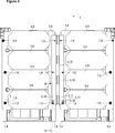
- Figure 3 – is a schematic partial top view of the cooking appliance of Fig. 1;
- Figure 4 – is a schematic enlarged sectional view of the cooking appliance of Fig. 3, taken along the line B-B.
- the mounting assembly (1) is suitable for use in a cooking appliance (2), in particular in an induction cooking appliance (2).
- the cooking appliance (2) comprises a casing (not shown), one or more functional components (3) which are disposed into the casing and a top plate (not shown) which is adapted to cover the upper side of the casing and to support the cooking utensils (not shown).
- the mounting assembly (1) comprises a support (4) which is adapted to accommodate one or more functional components (3) and one or more elastic elements (5) which are each disposed onto the support (4) and each adapted to push the respective functional component (3) on the support (4) upwards against the top plate (Fig. 1 to 4).
- each functional component (3) comprises a support member (8, 10, 12) and one or more functional units (9, 11, 13) each held by the support member (8, 10, 12) and one or more holes (7) which are formed into the support member (8, 10, 12), wherein the holes (7) are adapted to cooperate with the mounting assembly (1).
- the mounting assembly (1) of the present invention further comprises one or more vertically extending centering pins (6) which are each disposed onto the support (4) and each adapted to be freely inserted into a counterpart hole (7) of the respective functional component (3) on the support (4) so as to position and align the same relative to the top plate, wherein an elastic element (5) is disposed immediately below the hole (7) of each respective functional component (3) and around the respective centering pin (6).
- the cooking appliance (2) of the present invention comprises the mounting assembly (1).
- two or more functional components (3) respectively comprise holes (7) which mutually coincide.
- at least one vertically extending centering pin (6) is further adapted to be jointly freely inserted into the two or more mutually coinciding counterpart holes (7) of the respective functional components (3).
- an elastic element (5) is disposed immediately below the hole (7) of each respective functional component (3) and around the respective common centering pin (6).
- the support (4) is integrally formed with each vertically extending centering pin (6).
- the support (4), including each vertically extending centering pin (6) is moulded from a durable plastic material into a single piece.
- the support (4) is detachably attachable into the casing of the cooking appliance (2).
- the elastic elements (5) are each provided in form of a cylindrical or conical helical spring.
- the elastic elements (5) are made from rubber.
- three of the functional components (3) respectively comprise a first support member (8) which holds one or more induction coils (9), a second support member (10) which holds one or more illuminating indicators (11) and a third support member (12) which holds one or more infrared sensors (13).
- the first to third support members (8, 10, 12) respectively have holes (7) which mutually coincide.
- the vertically extending centering pin (6) is jointly freely inserted into these coinciding counterpart holes (7).
- the elastic element (5) is disposed immediately below the hole (7) of each respective support member (8, 10, 12) and around the respective common centering pin (6).
- Detail A’ of Fig. 1 shows a vertically extending centering pin (6) which is freely inserted into the counterpart hole (7) of the first support member (8) which holds a plurality of induction coils (9). Also one elastic element (5) is disposed immediately below the hole of the first support member (8) and around the respective centering pin (6).
- Detail A’’ of Fig. 1 shows another vertically extending centering pin (6) which is jointly freely inserted into the two coinciding counterpart holes (7) of the first to second support members (8, 10) which hold the plurality of induction coils (9) and the illuminating indicators (11) respectively.
- the elastic element (5) is disposed immediately below the hole (7) of each of the first to second support members (8, 10) and around the respective common centering pin (6).
- a major advantageous effect of the present invention is that the functional components (3) can be easily and reliably assembled into the casing at their installation positions by virtue of the mounting assembly (1), in particular the support (4), the elastic elements (5) and the centering pins (6). Thereby, the functional components (3) can be prevented from dislocating and thus the risk of any malfunctioning can be eliminated or reduced as much as possible.
- Another major advantageous effect of the present invention is that a large number of functional components (3) can be smoothly assembled into the casing at their installation positions by virtue of the mounting assembly (1). Thereby, the assembly operation can be expedited.
- Other additional advantageous effects of the present invention can be taken from the aforementioned particular embodiments.
Landscapes
- Engineering & Computer Science (AREA)
- Physics & Mathematics (AREA)
- Electromagnetism (AREA)
- Chemical & Material Sciences (AREA)
- Combustion & Propulsion (AREA)
- Mechanical Engineering (AREA)
- General Engineering & Computer Science (AREA)
- Induction Heating Cooking Devices (AREA)
Abstract
La présente invention concerne un ensemble de montage (1) destiné à être utilisé dans un appareil de cuisson (2) comprenant un boîtier et des composants fonctionnels (3) à l'intérieur du boîtier et une plaque supérieure. L'ensemble de montage (1) comprend un support (4) qui loge les composants fonctionnels (3) et des éléments élastiques (5) qui sont disposés sur le support (4) de manière à pousser les composants fonctionnels (3) respectifs vers le haut contre la plaque supérieure. L'ensemble de montage (1) de la présente invention comprend au moins une broche de centrage s'étendant verticalement (6) qui est disposée sur le support (4) et conçue pour être librement insérée dans un trou homologue (7) du composant fonctionnel (3) respectif sur le support (4) de manière à les positionner et à les aligner par rapport à la plaque supérieure.
Priority Applications (1)
| Application Number | Priority Date | Filing Date | Title |
|---|---|---|---|
| PCT/EP2015/068176 WO2017020964A1 (fr) | 2015-08-06 | 2015-08-06 | Ensemble de montage amélioré pour une utilisation dans un appareil de cuisson |
Applications Claiming Priority (1)
| Application Number | Priority Date | Filing Date | Title |
|---|---|---|---|
| PCT/EP2015/068176 WO2017020964A1 (fr) | 2015-08-06 | 2015-08-06 | Ensemble de montage amélioré pour une utilisation dans un appareil de cuisson |
Publications (1)
| Publication Number | Publication Date |
|---|---|
| WO2017020964A1 true WO2017020964A1 (fr) | 2017-02-09 |
Family
ID=53783752
Family Applications (1)
| Application Number | Title | Priority Date | Filing Date |
|---|---|---|---|
| PCT/EP2015/068176 Ceased WO2017020964A1 (fr) | 2015-08-06 | 2015-08-06 | Ensemble de montage amélioré pour une utilisation dans un appareil de cuisson |
Country Status (1)
| Country | Link |
|---|---|
| WO (1) | WO2017020964A1 (fr) |
Cited By (3)
| Publication number | Priority date | Publication date | Assignee | Title |
|---|---|---|---|---|
| EP3379900A1 (fr) * | 2017-03-24 | 2018-09-26 | E.G.O. ELEKTRO-GERÄTEBAU GmbH | Table de cuisson |
| US20210285655A1 (en) * | 2020-03-12 | 2021-09-16 | Lg Electronics Inc. | Electric range |
| EP4579133A4 (fr) * | 2022-09-02 | 2025-12-24 | Foshan Shunde Midea Electrical Heating Appliances Mfg Co Ltd | Dispositif de chauffage électromagnétique |
Citations (5)
| Publication number | Priority date | Publication date | Assignee | Title |
|---|---|---|---|---|
| DE102007032762A1 (de) * | 2006-08-07 | 2008-02-28 | BSH Bosch und Siemens Hausgeräte GmbH | Heizeinheitsbefestigungsvorrichtung |
| WO2008080944A2 (fr) * | 2006-12-29 | 2008-07-10 | Arcelik Anonim Sirketi | Appareil de cuisson |
| EP2079275A1 (fr) * | 2008-01-14 | 2009-07-15 | BSH Bosch und Siemens Hausgeräte GmbH | Champ de cuisson à induction doté d'un dispositif de fixation destiné à la fixation d'un support à induction sur un cadre de montage |
| GB2486802A (en) * | 2010-12-21 | 2012-06-27 | Aga Rangemaster Ltd | Induction hob with a spring and bracket |
| EP2775790A1 (fr) * | 2013-03-04 | 2014-09-10 | Miele & Cie. KG | Appareil de cuisson |
-
2015
- 2015-08-06 WO PCT/EP2015/068176 patent/WO2017020964A1/fr not_active Ceased
Patent Citations (5)
| Publication number | Priority date | Publication date | Assignee | Title |
|---|---|---|---|---|
| DE102007032762A1 (de) * | 2006-08-07 | 2008-02-28 | BSH Bosch und Siemens Hausgeräte GmbH | Heizeinheitsbefestigungsvorrichtung |
| WO2008080944A2 (fr) * | 2006-12-29 | 2008-07-10 | Arcelik Anonim Sirketi | Appareil de cuisson |
| EP2079275A1 (fr) * | 2008-01-14 | 2009-07-15 | BSH Bosch und Siemens Hausgeräte GmbH | Champ de cuisson à induction doté d'un dispositif de fixation destiné à la fixation d'un support à induction sur un cadre de montage |
| GB2486802A (en) * | 2010-12-21 | 2012-06-27 | Aga Rangemaster Ltd | Induction hob with a spring and bracket |
| EP2775790A1 (fr) * | 2013-03-04 | 2014-09-10 | Miele & Cie. KG | Appareil de cuisson |
Cited By (3)
| Publication number | Priority date | Publication date | Assignee | Title |
|---|---|---|---|---|
| EP3379900A1 (fr) * | 2017-03-24 | 2018-09-26 | E.G.O. ELEKTRO-GERÄTEBAU GmbH | Table de cuisson |
| US20210285655A1 (en) * | 2020-03-12 | 2021-09-16 | Lg Electronics Inc. | Electric range |
| EP4579133A4 (fr) * | 2022-09-02 | 2025-12-24 | Foshan Shunde Midea Electrical Heating Appliances Mfg Co Ltd | Dispositif de chauffage électromagnétique |
Similar Documents
| Publication | Publication Date | Title |
|---|---|---|
| US12055302B2 (en) | Control device for a modular hob system | |
| EP3177108B1 (fr) | Table de cuisson a induction | |
| WO2017020964A1 (fr) | Ensemble de montage amélioré pour une utilisation dans un appareil de cuisson | |
| US9004623B2 (en) | Door for a domestic appliance | |
| EP2016338B1 (fr) | Table de cuisson | |
| CN105723156A (zh) | 家用器件 | |
| US10619860B2 (en) | Range appliance and sensor assembly | |
| KR20160025170A (ko) | 인덕션 렌지의 온도퓨즈 장착구조체 | |
| AU2017326323B2 (en) | Device for operating a built-in kitchen appliance | |
| EP2487421A1 (fr) | Appareil domestique à gaz avec un système d'alimentation de gaz contrôlé magnétiquement | |
| US9599348B2 (en) | Cooktop with deformable hook | |
| EP2672186B1 (fr) | Four pour cuire des produits alimentaires | |
| CN206462858U (zh) | 温控器的安装结构和烹饪器具 | |
| EP3130858B1 (fr) | Plaque de cuisson | |
| CN211722760U (zh) | 烹饪器具 | |
| EP2397773B1 (fr) | Plaque de cuisson avec un ou plusieurs systèmes de chauffage | |
| CN109419320A (zh) | 煮饭器 | |
| CN214048478U (zh) | 线圈盘组件及具有其的烹饪器具 | |
| CN217302895U (zh) | 烹饪电器 | |
| US20130106563A1 (en) | Temperature switch | |
| EP2557363A2 (fr) | Appareil ménager électronique avec un capteur et son support | |
| CN219367706U (zh) | 烹调器和烹饪器具 | |
| CN214258920U (zh) | 煲体组件及具有其的烹饪器具 | |
| US20240230106A1 (en) | Removable bracket assembly for an oven appliance manifold | |
| CN212089209U (zh) | 烹饪器具 |
Legal Events
| Date | Code | Title | Description |
|---|---|---|---|
| 121 | Ep: the epo has been informed by wipo that ep was designated in this application |
Ref document number: 15747485 Country of ref document: EP Kind code of ref document: A1 |
|
| NENP | Non-entry into the national phase |
Ref country code: DE |
|
| 122 | Ep: pct application non-entry in european phase |
Ref document number: 15747485 Country of ref document: EP Kind code of ref document: A1 |