WO2017022757A1 - 視野計測方法、視野計測装置および視力検査視標 - Google Patents
視野計測方法、視野計測装置および視力検査視標 Download PDFInfo
- Publication number
- WO2017022757A1 WO2017022757A1 PCT/JP2016/072647 JP2016072647W WO2017022757A1 WO 2017022757 A1 WO2017022757 A1 WO 2017022757A1 JP 2016072647 W JP2016072647 W JP 2016072647W WO 2017022757 A1 WO2017022757 A1 WO 2017022757A1
- Authority
- WO
- WIPO (PCT)
- Prior art keywords
- target
- function
- peripheral
- display
- dark spot
- Prior art date
- Legal status (The legal status is an assumption and is not a legal conclusion. Google has not performed a legal analysis and makes no representation as to the accuracy of the status listed.)
- Ceased
Links
Images






Classifications
-
- A—HUMAN NECESSITIES
- A61—MEDICAL OR VETERINARY SCIENCE; HYGIENE
- A61B—DIAGNOSIS; SURGERY; IDENTIFICATION
- A61B3/00—Apparatus for testing the eyes; Instruments for examining the eyes
- A61B3/02—Subjective types, i.e. testing apparatus requiring the active assistance of the patient
- A61B3/024—Subjective types, i.e. testing apparatus requiring the active assistance of the patient for determining the visual field, e.g. perimeter types
-
- A—HUMAN NECESSITIES
- A61—MEDICAL OR VETERINARY SCIENCE; HYGIENE
- A61B—DIAGNOSIS; SURGERY; IDENTIFICATION
- A61B3/00—Apparatus for testing the eyes; Instruments for examining the eyes
- A61B3/0016—Operational features thereof
- A61B3/0025—Operational features thereof characterised by electronic signal processing, e.g. eye models
-
- A—HUMAN NECESSITIES
- A61—MEDICAL OR VETERINARY SCIENCE; HYGIENE
- A61B—DIAGNOSIS; SURGERY; IDENTIFICATION
- A61B3/00—Apparatus for testing the eyes; Instruments for examining the eyes
- A61B3/0016—Operational features thereof
- A61B3/0033—Operational features thereof characterised by user input arrangements
-
- A—HUMAN NECESSITIES
- A61—MEDICAL OR VETERINARY SCIENCE; HYGIENE
- A61B—DIAGNOSIS; SURGERY; IDENTIFICATION
- A61B3/00—Apparatus for testing the eyes; Instruments for examining the eyes
- A61B3/0016—Operational features thereof
- A61B3/0041—Operational features thereof characterised by display arrangements
-
- A—HUMAN NECESSITIES
- A61—MEDICAL OR VETERINARY SCIENCE; HYGIENE
- A61B—DIAGNOSIS; SURGERY; IDENTIFICATION
- A61B3/00—Apparatus for testing the eyes; Instruments for examining the eyes
- A61B3/02—Subjective types, i.e. testing apparatus requiring the active assistance of the patient
- A61B3/028—Subjective types, i.e. testing apparatus requiring the active assistance of the patient for testing visual acuity; for determination of refraction, e.g. phoropters
- A61B3/032—Devices for presenting test symbols or characters, e.g. test chart projectors
Definitions
- the present invention relates to a visual field measurement method, a visual field measurement device, and a visual acuity test target. More specifically, a visual field measurement method used for examining various diseases and the degree of progression of each disease, a visual field measurement device that implements this visual field measurement method, and used for measuring the minimum separation threshold of visual acuity. It is related to a vision test target.
- Visual function tests in ophthalmology play an important role in obtaining objective judgments such as understanding the pathology of eye diseases, determining treatment strategies, and verifying treatment effects.
- visual functions to be examined include visual acuity, visual field, and color vision as functions for inputting visual information from the eyes.
- visual acuity inspection is generally performed.
- visual acuity means a function (morphological sense) that recognizes the existence of an object and identifies what it is.
- This visual acuity (morphological sense) is classified into four types: “minimum visual recognition threshold”, “minimum separation threshold”, “minimum readable threshold”, and “sub-scale visual acuity”.
- minimum visual recognition threshold “minimum separation threshold”
- minimum readable threshold minimum readable threshold
- sub-scale visual acuity sub-scale visual acuity
- Landolt rings are used to measure this “minimum separation threshold”.
- the Landolt ring has a shape in which a notch is formed in a part of a donut-shaped ring, and the minimum separation threshold is measured based on whether or not the presence of this notch can be recognized.
- the size of the Landolt ring with different sizes is shown to the subject and the size of the notch can be recognized.
- the gap interval of the notch in the Landolt ring of the minimum size that can recognize the position of the notch can be set as the minimum separation threshold of the subject.
- visual field examinations are performed to examine diseases such as glaucoma, retinitis pigmentosa, diabetic retinopathy, retinal detachment, macular degeneration, and the degree of progression of each disease.
- diseases such as glaucoma, retinitis pigmentosa, diabetic retinopathy, retinal detachment, macular degeneration, and the degree of progression of each disease.
- a range that is visible when one point is observed is measured using a perimeter. Specifically, the face is fixed to the perimeter, and the subject is made to stare at the center mark shown on the display unit in the perimeter. In this state, light or the like appears around the display unit, and when the light is seen, the subject sounds a buzzer.
- the minimum separation threshold as described above essentially matches the retinal resolution, but in our experiments, the minimum separation threshold measured using the Landolt ring may not match the retinal resolution. It was revealed. In other words, although the Landolt ring is an internationally recognized inspection target, it has been confirmed that it does not actually have sufficient inspection accuracy for the minimum separation threshold.
- an object of the present invention is to provide a visual field measurement method and a visual field measurement device that can reduce the burden on a subject and a laboratory technician. It is another object of the present invention to provide a visual acuity test target suitable for automatic measurement, the visual field measurement method and the visual field measurement device of the present invention, which can match the minimum separation threshold obtained as a test result with the retinal resolution.
- the visual field measuring method of the first invention is a method for measuring the visual field by sequentially displaying the inspection target on the display unit, and displaying the inspection target at the reference position provided in the center of the display unit.
- the visual field measurement method is the visual field measurement method according to the first aspect, wherein the inspection target displayed in the reference target display step is an inspection target for inspecting visual acuity, and in the reference target display step, the inspection target is displayed. It is characterized by having the subject input the direction of the mark.
- the visual field measurement method is the first or second aspect of the invention, wherein the inspection target displayed in the peripheral visual target display step is an inspection visual target for inspecting visual acuity, and in the peripheral visual target display step, The direction of the inspection target is input to the subject, and a ratio at which the direction input by the subject in the peripheral input step and the direction of the inspection target displayed in the peripheral target display step are inconsistent is predetermined. Or when the direction input by the subject in the peripheral input step coincides with the direction of the test target displayed in the peripheral target display step, and the reaction time is a predetermined time. In this case, the peripheral position is determined as a dark spot.
- the visual field measuring method is the visual field measurement method according to the third aspect, wherein the offset time information of the inspection target displayed in the peripheral target display step is a horizontal axis and the reaction time is the vertical axis and the reaction time is plotted as a linear graph. A dark spot is determined based on an approximate line obtained by approximation.
- the visual field measurement method is the visual field measurement method according to the fourth aspect, wherein the approximate line is formed using data excluding dark spot candidates, and a dark spot separation line parallel to the approximate line based on the dark spot candidates And the dark spot candidate is determined as a dark spot if the reaction time is later than the dark spot separation line.
- a visual field measurement method is characterized in that, in the fifth invention, a dark spot discriminant line is calculated from data located at a Marriott blind spot among the dark spot candidates.
- the visual field measurement method according to a seventh aspect of the present invention is the visual field measurement method according to any one of the first to sixth aspects, wherein an inspection target for inspecting visual acuity having a different size is displayed at the reference position, and the test target is displayed after the inspection target is displayed. The reaction time until the direction of the inspection target is inputted is measured, and the size of the inspection target used for the visual field inspection is determined based on the relationship between the size of the inspection target and the reaction time.
- the visual field measurement method is characterized in that, in any one of the first to seventh aspects, the inspection target is an ARO.
- a visual field measuring apparatus includes a display unit that displays an inspection target, an input unit that causes the subject to input that the inspection target displayed on the display unit has been recognized, and the display unit that includes the inspection target.
- a display control unit for controlling the position and timing for displaying the reference target, and the display control unit includes a reference target display function for displaying an inspection target at a reference position in the display unit, and the display unit, A peripheral target display function for displaying an inspection target at a peripheral position different from the reference position, and a display switching function for switching between the reference target display function and the peripheral target display function based on a signal from the input unit; And a reaction time measurement function for measuring a time from when the test target is displayed by the peripheral target display function to when the test subject is input to the input unit.
- the visual field measuring apparatus is the inspection target displayed in the reference position of the display unit by the reference target display function according to the ninth aspect of the invention, and is an inspection target for inspecting visual acuity.
- the test target is recognized by the subject who has recognized the test target displayed at the reference position on the display unit by the reference target display function, and the direction of the test target is input.
- the field-of-view measurement apparatus is the inspection target displayed in the reference position of the display unit by the peripheral target display function according to the ninth or tenth aspect of the invention.
- the input unit is configured to cause the subject who has recognized the test target displayed at the reference position in the display unit by the peripheral target display function to input the direction of the test target, and the display control unit , Has a dark spot judging function for judging a dark spot based on an input to the input section, and the dark spot judging function is inputted to the input section when the inspection target is displayed at the peripheral position.
- the dark spot determination function is the measurement using the offset information of the inspection target displayed by the peripheral target display function as the horizontal axis and the reaction time as the vertical axis.
- the visual field measurement apparatus is the visual field measurement apparatus according to the twelfth aspect, wherein the dark spot determination function forms the approximate line using data excluding dark spot candidates, and the approximate line based on the dark spot candidates.
- a dark spot separation line parallel to the dark spot is calculated, and among the dark spot candidates, a function having a reaction time slower than that of the dark spot separation line is determined as a dark spot.
- the dark spot determination function has a function of calculating a dark spot determination line using data located at a Marriott blind spot among the dark spot candidates.
- the visual field measurement device is any one of the ninth to fourteenth aspects, wherein the display control unit determines a size of an inspection target to be displayed at the reference position and the peripheral position.
- the target size determination function displays an inspection target for inspecting visual acuity having a different size at the reference position, and the test subject displays the direction of the inspection target after the inspection target is displayed.
- the reaction time measurement function for measuring the reaction time until the input of the test time, and the size of the inspection target used for the visual field inspection based on the relationship between the reaction time measured by the reaction time measurement function and the size of the inspection target It is characterized by having a sizing function for determining the size.
- the visual field measurement apparatus according to a sixteenth aspect of the present invention is characterized in that, in any of the ninth to fifteenth aspects, the inspection target is an ARO. (Vision test target)
- the visual acuity test target according to the seventeenth aspect of the invention is a test target used for the inspection of the minimum separation threshold, and a pair of parallel lines provided in parallel to each other and between the opposing edges of the pair of parallel lines.
- the pair of parallel lines are formed to have the same length, and the connection lines are provided so as to be orthogonal to the pair of parallel lines.
- the line width of the pair of parallel lines, the width of the gap between the pair of parallel lines, and the line width of the connecting lines are all formed to have the same length.
- the visual acuity test target according to an eighteenth aspect of the present invention is the visual inspection test target according to the seventeenth aspect of the present invention, wherein the inspection visual target is formed so that the length of the pair of parallel lines is the same as the distance between the outer edges of the pair of parallel lines. It is characterized by being.
- the visual acuity test target according to the nineteenth aspect of the invention is characterized in that, in the seventeenth or eighteenth aspect, the ratio between the length and the line width of the pair of parallel lines is adjusted to be 2: 1 to 5: 1. And
- the first aspect of the invention it is possible to accurately measure the Marriott blind spot and dark spot with a simple and short test. Then, it can contribute to early detection of diseases such as glaucoma, retinitis pigmentosa, diabetic retinopathy, retinal detachment, macular degeneration, and evaluation / determination of the degree of progression of each disease.
- the 2nd invention since a test subject's eyes
- the difference in reaction time depending on the display position of the test target can be corrected, so that the dark spot can be determined more accurately.
- the dark spot determination line is formed using the dark spot candidate data, the precision of determining the dark spot can be increased.
- the dark spot determination line is formed using the data of the Marriott blind spot which is a dark spot without fail, the accuracy of determining the dark spot can be further increased.
- the size of the inspection target used for the visual field inspection can be set to an appropriate size, the reaction time can be stabilized. Therefore, the inspection accuracy of the visual field inspection using the inspection target can be improved.
- the test target can be recognized by the subject according to the actual visual acuity of the subject, so that the test accuracy can be increased.
- Visual field measuring device According to the ninth aspect of the invention, it is possible to accurately measure the Marriott blind spot and the dark spot with a simple and short test. Then, it can contribute to early detection of diseases such as glaucoma, retinitis pigmentosa, diabetic retinopathy, retinal detachment, macular degeneration, and evaluation / determination of the degree of progression of each disease. According to the tenth invention, the visual line of the subject can be surely directed to the reference position, so that the inspection accuracy can be increased.
- the eleventh aspect of the present invention it is possible to reduce a determination error for determining that a dark spot is normal, so that the dark spot can be detected with high accuracy.
- the dark spot since the difference in reaction time depending on the display position of the test target can be corrected, the dark spot can be determined more accurately.
- the dark spot determination line is formed using the dark spot candidate data, the precision of determining the dark spot can be increased.
- the dark spot determination line is formed using the data of the Marriott blind spot which is a dark spot without fail, the accuracy of determining the dark spot can be further increased.
- the reaction time can be stabilized. Therefore, the inspection accuracy of the visual field inspection using the inspection target can be improved.
- the test target can be recognized by the subject according to the actual visual acuity of the subject, the test accuracy can be increased.
- the inspection target does not have a curved portion, the time for waiting for display of the inspection target can be shortened, so that the inspection time can be shortened.
- the visual field inspection can be automated. (Vision test target)
- a minimum separation threshold that matches the retinal resolution can be obtained.
- the inspection target can be displayed accurately and at high speed when digitally displayed. Therefore, it is possible to automate the visual acuity test.
- FIG. It is a schematic explanatory drawing of the visual field measuring method by the visual field measuring apparatus 1 of this embodiment.
- the visual field measuring method by the visual field measuring apparatus 1 of the present embodiment it is a schematic explanatory diagram when the target to be displayed at the peripheral position SP is changed. It is a map of the position which measures a dark spot. It is a figure of an experimental result. It is a figure of an experimental result. It is a figure of an experimental result. It is a figure of an experimental result. It is a figure of an experimental result. It is a figure of an experimental result.
- (A) is a figure which shows the relationship between target size and reaction time
- (B) is the figure which showed an example of the dark spot determination area in a display map.
- (A) is the figure which showed the dark spot discriminant line
- (B) is the table
- the visual field measurement method according to the present invention is a method for detecting a lack or the like by inspecting the visual field of a subject, and is characterized in that the inspection can be easily performed.
- the visual field measuring device of the present invention is a device used for visual field inspection of a subject, and is characterized in that the inspection can be easily performed.
- the visual acuity test target of the present invention is an inspection target used to test a minimum separation threshold, and obtains a minimum separation threshold that matches the retinal resolution compared to a conventional inspection target such as a Landolt ring. It has a feature in that it can be shaped.
- the visual acuity test target of the present invention is suitable not only for the inspection of the minimum separation threshold but also as the inspection target used when inspecting the human visual field. Specifically, it can be used as an inspection target of the visual field inspection method of the present invention for determining the position of a human dark spot and the presence or absence of a dark spot.
- ARO Accele Resolution Optotype
- FIG. 2 (A) shows ARO.
- This ARO is composed of an annular line Ar (lines A1 to A3), similar to the Landolt ring L (FIG. 2 (B)) used to perform the conventional visual acuity test (that is, the minimum separation threshold test). In which a notch Ag is formed.
- the circular line Lr is circular, and the portion surrounded by the line Lr is also circular.
- an annular line Ar (formed by lines A1 to A3) is a rectangle, and a portion surrounded by the line Ar is also a rectangle.
- the circular line Ar does not have a curved portion and is formed only by a straight line.
- the diameter ld of the portion surrounded by the line Lr and the width lg of the notch Lg are completely different.
- the width ad of the rectangular portion surrounded by the line Ar and the width ag of the notch Ag are formed to be the same width.
- the notch Lg has the same width lg and line width lw, but the notch shape is not rectangular.
- the width Ag of the notch Ag is formed to be the same width as the line width aw of the annular line Ar (that is, each of the lines A1 to A3) and is rectangular.
- the ARO Since the ARO has the same coincidence point as described above with the Landolt ring L, it can be used for the visual acuity test like the Landolt ring L if an ARO whose position and size are changed is used. That is, it is possible to inspect whether the ARO has a visual acuity capable of recognizing the width ag of the notch Ag by notifying the position where the notch Ag of the ARO is located.
- ARO since ARO has the above-mentioned differences from the Landolt ring L, an accurate visual acuity test can be performed as compared with the Landolt ring L. That is, when a visual acuity test is performed by ARO, a test result in which the minimum separation threshold detected by the visual acuity test is matched with the retinal resolution can be obtained.
- the reason is as follows. First, when a minimum stripe width that can be recognized as a stripe pattern is measured using a stripe pattern, the minimum stripe width substantially matches the retina resolution. When the spatial frequency spectrum is analyzed for this striped pattern, a spatial frequency peak is obtained.
- the spatial frequency (peak frequency) at which this peak is obtained is the spatial frequency that the subject can most easily discriminate, in other words, the minimum stripe width that can be recognized by the subject and that is detected using a striped pattern.
- ARO and Landolt ring L visual acuity is inspected based on whether or not the notch can be recognized. Then, it can be considered that the ARO and the Landolt ring L are examining visual acuity depending on whether the notch can be recognized as a stripe. Therefore, if the peak frequency in the spatial frequency spectrum of the ARO or Landolt ring L is the same as the peak frequency in the spatial frequency spectrum of the striped pattern having the same line width as the notch width of the ARO or Landolt ring L, then the ARO or Landolt ring L The result of the visual acuity test is considered to coincide with the minimum stripe width measured using the stripe pattern. In other words, it can be considered that the result (minimum separation threshold) of the visual acuity test of the ARO or the Landolt ring L can be matched with the retinal resolution.
- the spatial frequency spectrum of the Landolt ring L When the spatial frequency spectrum of the Landolt ring L is analyzed, it has a peak at a spatial frequency smaller than the spatial frequency to be originally identified (that is, the frequency of the notch), and has a peak at the peak frequency of the striped pattern having the same line width. I don't have it. That is, in the visual acuity test of the Landolt ring L, it can be considered that the subject can recognize even if the width is narrower than the retinal resolution, but the subject's retinal resolution may not be appropriately examined.
- ARO since ARO does not have a curved portion, it can be displayed accurately and at high speed when displayed on a display device.
- the ARO can be displayed by simply specifying the display position (that is, the cell to be displayed).
- ARO can be displayed with the number of pixels of 3 pixels ⁇ 3 pixels, and its shape can be clearly displayed.
- the visual acuity test using the ARO can be performed using a smartphone, a tablet terminal, or the like. That is, an eyesight test can be easily performed even by an individual.
- the ARO is appropriately displayed and the result can be input, it is possible to automate the visual acuity test.
- the ARO is not limited to a visual target for visual acuity inspection, but can be incorporated into a visual field inspection (described later), which is another visual function inspection, to improve the accuracy of each inspection.
- the ARO includes a pair of parallel lines A1 and A2 provided in parallel to each other.
- the pair of parallel lines A1 and A2 are formed to have the same length, and their opposite edges (the left end in FIG. 2A) are connected by a connecting line A3.
- the connecting line A3 is provided so as to be orthogonal to the pair of parallel lines A1 and A2. That is, the ARO is formed in a Katakana U-shape (a square U-shape in the case of an alphabet).
- ARO has the same line width of the pair of parallel lines A1 and A2, the width of the gap between the pair of parallel lines A1 and A2 (that is, the width of the notch Ag), and the line width of the connecting line A3. It is formed to be a length. Since it is formed in such a shape, ARO can obtain the effects as described above.
- the ARO is formed such that the lengths s1, s2 of the pair of parallel lines A1, A2 and the distance s3 between the outer edges of the pair of parallel lines A1, A2 are the same length. This is because the ARO has a square shape. In the visual acuity test, it is necessary to make it impossible to estimate the position of the notch based on the outer shape of the target. By making the ARO square, it becomes impossible to estimate the notch direction by rotating the outer shape. That is, an accurate visual acuity test can be performed by making the ARO square.
- Visual field inspection If the above-described visual acuity test target (ARO) is used, a visual field inspection, specifically, whether a dark spot exists in the visual field or not can be quickly and easily performed by an inspection device as described later. Can do.
- ARO visual acuity test target
- the movement of the line of sight has to be fixed during the inspection, and the face of the subject must be fixed and the line of sight must be fixed.
- the test had to be performed with the entire front face of the subject covered.
- the inspection engineer had to operate the apparatus and monitor inspection errors.
- the visual field inspection apparatus 1 uses the above-described visual acuity test target.
- the visual field inspection apparatus 1 includes a display unit 2, an input unit 3, a storage unit 4, and a display control unit 10.
- the position where the display control unit 10 displays an ARO (inspection target) on the display unit 2 is changed.
- the structure which inputs from the input part 3 the position which the notch Ag of displayed ARO exists is employ
- the inspection target displayed by the visual field inspection device 1 is not limited to ARO, and other inspection targets can be used.
- ARO is used as a test target, the test target can be recognized by the subject according to the actual visual acuity of the test subject, so that the test accuracy can be increased.
- the ARO does not have a curved portion, it can be displayed on the display unit 2 accurately and at high speed. Accordingly, since the time for waiting for the display of the inspection target can be shortened, the inspection time can be shortened. Furthermore, since there is no inspection omission due to a display error or the like, the visual field inspection by the visual field inspection apparatus 1 can be automated.
- the targets to be displayed at the reference position BP and the peripheral position SP described later do not need to be the same type of target. That is, the types of visual targets displayed at the reference position BP and the peripheral position SP may be changed. For example, ARO may be displayed at the reference position BP, and characters or the like may be displayed at the peripheral position SP.
- the target displayed at the peripheral position SP may be a simple black spot or the like as long as the subject can recognize that the target is displayed (see FIG. 4).
- the input unit 3 to be described later only needs to allow the subject to input that the target at the peripheral position SP has been recognized.
- the input unit 3 is a keyboard or the like, not only a specific key but also any key may be pressed to recognize that an appropriate input has been made.
- an inspection target such as ARO as the target displayed at the reference position BP in order to ensure that the subject's line of sight is directed to the reference position BP.
- the display unit 2 can display information supplied from the display control unit 10 or the outside based on instructions from the display control unit 10 or the outside. Specifically, ARO can be displayed at a predetermined position (a reference position BP or a peripheral position SP described later) based on an instruction from the display control unit 10.
- the display unit 2 may use any display device as long as the ARO can be displayed at a certain high speed.
- a known display device such as a liquid crystal display or a plasma display can be used.
- the size of the display unit 2 is not particularly limited, but it is desirable that the display unit 2 is as small as possible because the apparatus can be made compact.
- the field of view in which a person can recognize characters and the like is at most about 30 degrees from the center of the field of view. Therefore, for example, when the viewing distance (distance from the subject to the display unit 2) is 450 mm and the length and width are about 300 mm ⁇ 520 mm (23-inch display), the size of the display unit 2 is sufficiently large. Inspection can be performed.
- the shape of the display unit 2 is not particularly limited, and may be a square or a rectangle, or other shapes.
- the display unit 2 can be a head mounted display having a screen such as a liquid crystal inside.
- a head-mounted display makes it easier to fix the distance from the human eye to the screen.
- the screen moves with the movement of the face, so that the influence of the movement of the face can be eliminated.
- a right-eye display and a left-eye display are provided, the screen for one eye cannot be viewed with the other eye. Then, an examination using both eyes and an examination of only one eye can be easily performed. And if the subject cannot recognize which eye is being examined, such as by conducting a random examination of the left and right eyes, it can prevent the subject from manipulating the test results. Therefore, the inspection accuracy can be increased.
- the images displayed on the screens for the right eye and the left eye are respectively displayed for each eye. Adjust the images displayed on each screen so that people do not feel uncomfortable when they see them.
- the input unit 3 is for allowing the subject to input the direction of the ARO displayed on the display unit 2.
- the input unit 3 allows the subject to input the direction of the ARO, specifically, the position where the notch Ag of the ARO is arranged in four directions, up, down, left and right.
- an input device such as a keyboard, joystick, or mouse can be used as the input unit 3.
- Use of the cursor keys of the keyboard is preferable because the influence of the proficiency on the operation of the input device can be reduced. Even when the joystick is used, the influence of the proficiency on the operation of the input device can be reduced because the joystick is simply cut and tilted in the direction of Ag (up and down is front and rear).
- the input unit 3 When there is an input from the subject, the input unit 3 also has a function of transmitting a signal notifying that there is an input to the display control unit 10 (specifically, each function of the display control unit 10). ing.
- the storage unit 4 is connected to the display control unit 10, and has a function of transmitting information from each function of the display control unit 10 and storing the information. For example, the information about the displayed ARO or the position where the ARO is displayed, transmitted from the peripheral target display function 12 of the display control unit 10, the direction input to the input unit 3, and the reaction time described later are associated with each other. And has a function to memorize.
- the storage unit 4 also has a function of supplying the stored information to the display unit 2 and transmitting it to the outside based on instructions from the display control unit 10 and the outside.
- the display control unit 10 has a function of controlling the position and timing for displaying the ARO on the display unit 2. That is, the display control unit 10 controls the display of the ARO based on the signal from the input unit 3.
- the display control unit 10 includes a reference target display function 11, a peripheral target display function 12, a display switching function 13, a reaction time measurement function 14, and a dark spot determination function 15.
- the reference target display function 11 has a function of displaying ARO at the reference position BP of the display unit 2. Specifically, when a command is transmitted from the display switching function 13, the reference target display function 11 includes information on the position of the reference position BP and information including ARO information displayed on the reference position BP (reference display information). Is transmitted to the display unit 2 and ARO is displayed on the display unit 2.
- the information related to the position of the reference position BP is information such as the coordinates of the reference position BP on the display unit 2.
- the reference position BP is a preset position, and is set to an appropriate position depending on the shape and size of the display unit 2.
- the reference position BP can be set at the center of the display unit 2.
- the reference position BP may be set at a position slightly deviated from the center of the display unit 2.
- the ARO information to be displayed at the reference position BP is information on the size of the ARO to be displayed and the direction of the ARO.
- the size of the ARO displayed by the reference target display function 11 may be a predetermined size or may be changed to an appropriate size according to the subject. For example, the visual acuity of the subject can be measured by the ARO, and an ARO that is slightly larger (for example, one step larger) than the ARO that has reached the visual acuity limit can be used.
- the direction of the ARO displayed by the reference target display function 11 may be changed randomly, or may always be a constant direction.
- the timing for displaying the ARO at the reference position BP by the reference target display function 11 is performed based on a command from the display switching function 13. That is, when the command from the display switching function 13 is input, the reference target display function 11 starts processing to display ARO at the reference position BP.
- the reference target display function 11 may enter a process of displaying an ARO at the same time when a command from the display switching function 13 is input, or a process of displaying an ARO after a certain period of time has elapsed. You may make it enter. In the former case, there is an advantage that the inspection can be carried out quickly, and in the latter case, there are advantages such as reducing the fatigue of the subject.
- the reference target display function 11 also has a function of stopping (disappearing) the display of the ARO. Specifically, when a signal is input from the input unit 3 to the reference target display function 11 in a state where the ARO is displayed, the display of the ARO is stopped (disappears). Yes. Of course, when the display switching function 13 switches from the reference target display function 11 to the peripheral target display function 12, that is, when a command is transmitted from the display switching function 13 to the peripheral target display function 12, The mark display function 11 may stop (disappear) the display of the ARO.
- the peripheral visual target display function 12 has a function of displaying ARO at a place (peripheral position SP) other than the reference position BP of the display unit 2. Specifically, when a command is transmitted from the display switching function 13, the peripheral visual target display function 12 is information including information related to the position of the peripheral position SP and information about the ARO to be displayed at the peripheral position SP (peripheral display information). Is transmitted to the display unit 2 and the ARO is displayed on the display unit 2.
- the information regarding the position of the peripheral position SP is information such as coordinates for displaying the peripheral position SP on the display unit 2.
- the peripheral position SP for displaying the ARO is determined at random.
- the peripheral target display function 12 may be provided with a random number generation function, and the peripheral position SP where the ARO is displayed may be determined based on the random number generated by the random number generation function.
- a predetermined display map or the like may be stored in the storage unit 4, and the peripheral position SP where the ARO is displayed may be determined based on the display map or the like.
- a random number generation function, a display map, and the like may be provided in the display switching function 13, and the peripheral position SP for displaying the ARO may be determined based on a command transmitted from the display switching function 13.
- the ARO information to be displayed at the peripheral position SP is information on the size of the ARO to be displayed and the direction of the ARO.
- the direction of the ARO displayed by the peripheral visual target display function 12 is also determined at random.
- the peripheral target display function 12 may be provided with a random number generation function, and the ARO orientation may be determined based on the random number generated by the random number generation function.
- a predetermined display map or the like may be stored in the storage unit 4 and the ARO orientation may be determined based on the display map or the like.
- a random number generation function, a display map, and the like may be provided in the display switching function 13, and the direction of the ARO to be displayed may be determined based on a command transmitted from the display switching function 13.
- the size of the ARO to be displayed may be a predetermined size or may be changed to an appropriate size according to the subject.
- the visual acuity of the subject can be measured by the ARO, and an ARO that is slightly larger (for example, one step larger) than the ARO that has reached the visual acuity limit can be used.
- the timing for displaying the ARO at the peripheral position SP by the peripheral visual target display function 12 is performed based on a command from the display switching function 13.
- the peripheral visual target display function 12 starts a process of displaying ARO at the peripheral position SP.
- the peripheral visual target display function 12 may enter a process of displaying ARO at the same time when a command from the display switching function 13 is input, or may be a process of displaying ARO after a certain period of time has elapsed. You may make it enter.
- the inspection can be carried out quickly
- advantages such as reducing the fatigue of the subject.
- the peripheral visual target display function 12 also has a function of stopping (disappearing) ARO display. Specifically, when a signal is input from the input unit 3 to the peripheral target display function 12 in a state where the ARO is displayed, the display of the ARO is stopped (disappears). .
- the display switching function 13 is switched to the reference target display function 11 from the peripheral target display function 12, that is, when a command is transmitted from the display switching function 13 to the reference target display function 11, The mark display function 12 may stop (disappear) the display of the ARO.
- the display switching function 13 has a function of switching the function of displaying the inspection target between the reference target display function 11 and the peripheral target display function 12 based on the input from the input unit 3. Specifically, it has a function of determining which one of the reference visual target display function 11 and the peripheral visual target display function 12 to operate based on an input from the input unit 3.
- the input unit 3 notifies the display switching function 13 that there is an input. Upon receiving this notification, the display switching function 13 switches the function of displaying the ARO from the reference target display function 11 to the peripheral target display function 12.
- the input unit 3 notifies the display switching function 13 that there is an input.
- the display switching function 13 switches the function of displaying the ARO from the peripheral target display function 12 to the reference target display function 11.
- reaction time measurement function 14 has a function of measuring the time from when the ARO is displayed by the peripheral visual target display function 12 until the direction of the ARO is input to the input unit 3.
- peripheral display information is transmitted from the peripheral visual target display function 12 to the display unit 2
- a signal is transmitted from the peripheral visual target display function 12 to the reaction time measurement function 14 at the same time.
- the reaction time measurement function 14 starts measuring time.
- the reaction time measurement function 14 ends the time measurement, and transmits the measured reaction time to the storage unit 4.
- the reaction time is stored together with information on the peripheral position SP.
- the reaction time measurement function 14 simply stores the time when the signal is transmitted from the peripheral visual target display function 12 and the time when the signal is transmitted from the input unit 3 without measuring the reaction time. The time may be transmitted to the storage unit 4.
- the dark spot determination function 15 has a function of determining whether or not the peripheral position SP is a dark spot based on the reaction time measured by the reaction time measurement function 14. In addition, the dark spot determination function 15 has a function of storing dark spot information in the storage unit 4 in association with information on the peripheral position SP and reaction time when the peripheral position SP is determined as a dark spot. .
- the dark spot determination function 15 is simply used when the time from when ARO is displayed at the peripheral position SP until the direction is input to the input unit 3 exceeds a certain value, or when the input direction is incorrect. If it is, the position can be determined as a dark spot.
- the dark spot can be determined by the following method.
- the dark spot determination function 15 may have a short reaction time when the ratio between the direction of the ARO displayed at the peripheral position SP and the direction input to the input unit 3 exceeds a predetermined value.
- the position is determined as a dark spot. Specifically, when the direction of the ARO displayed at the peripheral position SP is different from the direction input to the input unit 3 (recognition error), the interval is set for the peripheral position SP where the recognition error has occurred. It is vacant and ARO is displayed a plurality of times. Then, when the rate (number of times) of recognition errors is equal to or greater than a predetermined value, the position can be determined as a dark spot.
- the dark spot determination function 15 determines the position. It can be determined as a dark spot.
- the dark spot is determined by such a method, it is possible to reduce the determination error of determining that the dark spot is normal, so that the dark spot can be detected with high accuracy.
- a signal is also sent to the dark spot determination function 15. May be transmitted.
- the peripheral position SP is set as the dark spot. Is provided in the dark spot determination function 15.
- a function for transmitting a signal for switching the display function from the peripheral target display function 12 to the reference target display function 11 is provided in the dark point determination function 15 for the display switching function 13. Then, the inspection can be advanced without waiting for input more than necessary, and the inspection time can be shortened.
- a signal may be transmitted from the dark spot determination function 15 to the peripheral visual target display function 12.
- the display of the ARO displayed at the peripheral position SP is stopped even if no signal is input from the input unit 3 ( It is desirable to provide the peripheral visual target display function 12 with a function to be extinguished.
- the dark spot determination function 15 is not necessarily provided.
- the dark spot determination function 15 may not be provided.
- the dark spot determination function 15 may be included in the peripheral visual target display function 12, the display switching function 13, the reaction time measurement function 14, and the like.
- the size of the ARO displayed at the reference position BP or the peripheral position SP is not particularly limited. However, in order to improve the inspection accuracy, it is desirable to measure the recognition ability of the subject immediately before the inspection and determine the size of the ARO to be displayed on the display unit 2 based on the result. That is, it is desirable that the display control unit 10 has a target size determining function 16 that determines the size of the ARO.
- the target size determination function 16 transmits information about the size and orientation of the ARO to be displayed at the reference position BP to the display unit 2, displays the ARO on the display unit 2, and the ARO displays on the display unit 2.
- reaction time measurement function 16a stops (disappears) the display of the ARO and displays AROs of different sizes (or the same size) on the display unit 2. It also has a function to be displayed.
- the target size determination function 16 determines the size of the ARO as the inspection target from the size of the ARO and the measured reaction time. Has a function (size determination function 16b).
- the size determination function 16b also has a function of transmitting information regarding the determined size to the reference target display function 11, the peripheral target display function 12, the display switching function 13, the storage unit 4, and the like.
- the size determination function 16b determines the size of the ARO used as the inspection target based on the following criteria.
- the reaction time is usually slower as ARO is smaller and faster as ARO is larger.
- ARO becomes larger than a certain level the reaction rate becomes almost constant even when ARO becomes large (see the circled portion in FIG. 10A). Therefore, in the target size determination function 16, the minimum size at which the measured reaction time is constant is set as the test target.
- the reaction time can be stabilized, and the visual field inspection accuracy can be improved.
- inspection target can be employ
- the size of the ARO used as the inspection target is such that the measured reaction time is constant and is as small as possible. In particular, in order to increase the accuracy of the inspection, it is more desirable to set the minimum size at which the measured reaction time is constant.
- the size of the ARO displayed on the display unit 2 is sequentially changed from small to large (or from large to small). You may make it go. You may change a size at random.
- the target size determination function 16 may be ended when the measurement of the reaction time at the maximum (or minimum) size is completed.
- the target size determination function 16 may be ended when the measurement of the reaction time is completed for all sizes of ARO within a certain range.
- the ARO of the same size when determining the target size, the ARO of the same size may be displayed only once and the reaction time may be used, or the same size of ARO may be displayed multiple times. You may display and use the average value of the reaction time. And when an incorrect input is made, it may have a function of displaying AROs having the same size and different orientations again.
- the subject faces the display unit 2 and the distance from the display unit 2 to the eyes (viewing distance) is maintained at a constant distance.
- the viewing distance from the display unit 2 to the eyes is maintained at about 50 cm.
- any method may be employed to maintain the distance.
- it is not necessary to fix the movement of the face as in the conventional visual field inspection apparatus, and it is not necessary to block external light. Therefore, it is sufficient to provide a chin rest and place the chin on the chin rest.
- the display unit 2 can be configured with a head mounted display. In this case, the viewing distance is necessarily fixed.
- the examination is started.
- the test starts when the subject presses a key on the keyboard. Note that any method may be employed for instructing the inspection start.
- the size of the ARO used for the inspection is determined by the target size determination function 16. That is, AROs having different sizes are sequentially displayed at the reference position BP, and the reaction time input to the input unit 3 is measured. Based on the ARO size and the reaction time, the target size is determined by the target size determination function 16. When the target size is determined, information on the determined target size is transmitted to the reference target display function 11, the peripheral target display function 12, the display switching function 13, the storage unit 4, and the like.
- a confirmation process for confirming the reference position BP is executed by the reference target display function 11.
- a confirmation screen for causing the subject to recognize the reference position BP is displayed.
- ARO is displayed at the center of the screen, and then the display of ARO is once erased.
- the above confirmation process is performed simultaneously with the start of the inspection without performing the operation of determining the target size.
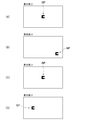
- ARO is displayed at the reference position BP at the center of the screen (FIG. 3A).
- the subject confirms the direction of the ARO displayed at the reference position BP, the subject inputs the direction of the ARO from the input unit 3.
- the display switching function 13 switches from the reference target display function 11 to the peripheral target display function 12.
- the display switching function 13 does not switch from the reference target display function 11 to the peripheral target display function 12, but the reference target display function. 11 is continued.
- the peripheral visual target display function 12 displays ARO at the peripheral position SP (FIG. 3B).
- the subject confirms the orientation of the ARO displayed at the peripheral position SP
- the subject inputs the orientation of the ARO from the input unit 3.
- the reaction time is measured by the reaction time measurement function 14.
- the measured reaction time is stored in the storage unit 4 together with the peripheral display information.
- the peripheral target display function 12 is switched to the reference target display function 11 by the display switching function 13. Then, the reference target display function 11 displays ARO again at the reference position BP (FIG. 3C).
- the display switching function 13 does not switch from the peripheral target display function 12 to the reference target display function 11, and the peripheral target display function.
- the display by 12 may be continued.
- the reaction time measurement function 14 also does not measure the reaction time and is maintained in a standby state.
- the test subject confirms the direction of the ARO displayed at the reference position BP, and inputs the direction of the ARO from the input unit 3. Then, the display switching function 13 switches again from the reference target display function 11 to the peripheral target display function 12, and the peripheral target display function 12 displays ARO at the peripheral position SP (FIG. 3D).
- the reaction time is measured by the reaction time measurement function 14, and is stored in the storage unit 4 together with the peripheral display information.
- the peripheral target display function 12 is switched to the reference target display function 11 by the display switching function 13.
- the above operation is repeated a predetermined number of times, and when the reaction time of a predetermined number of peripheral positions SP is measured, the inspection is finished.
- the visual field inspection apparatus 1 of the present embodiment only the direction of the ARO displayed by the reference visual target display function 11 and the peripheral visual target display function 12 is input. For this reason, it can test
- the display control unit 10 may be provided with only one display function, and this display function may be provided with all the functions of the reference target display function, the peripheral target display function, and the display switching function described above.
- ARO may be alternately displayed at the reference position BP and the peripheral position SP in accordance with an input from the input unit 3.
- reaction time measurement function 14 does not necessarily have to be provided independently.
- the function of the reaction time measurement function 14 may be provided by the above-described one display function (the display switching function 11, the peripheral target display function 12, etc.).
- the visual field inspection apparatus 1 may have a map forming function for displaying the inspection result as a map (dark spot map). If the results are displayed as a dark spot map, the distribution of dark spots can be grasped visually, so that it can be easily used for disease diagnosis.
- the determination as to whether or not it is a dark spot by the dark spot determination function 15 may be determined by the method as described above, but if the following determination method is used, the dark spot can be determined more accurately. .
- reaction time described above usually includes the following times.
- Target discovery time (a) (2) Eye movement (saccade) time (b) (3) Gap discrimination time (c) (4) Key press exercise time (d)
- reaction time T1 can be calculated
- T1 target discovery time (a) + eye movement (saccade) time (b) + gap discrimination time (c) + key press movement time (d)
- the target discovery time (a) and the line-of-sight movement (saccade) time (b) vary depending on the position where the ARO is displayed. That is, depending on the distance from the reference position BP, the reaction time T1 differs regardless of whether it is a dark spot. In other words, if the distance from the reference position BP to the peripheral position SP is long, a dark spot may be determined even if it is not a dark spot unless the reaction time T1 for determining the dark spot is appropriately set. There is.
- the target discovery time (a), the gaze movement (saccade) time (b), the gap discrimination time (c), and the key press movement time (d) are all considered to have individual differences. Then, the reaction time T1 determined to be a dark spot cannot be set to the same time for a subject having a long time and a subject having a short time.
- the gap discriminating time (c) and the key pressing time (d) are considered to be almost the same for the same subject once the ARO is found. Further, since the target discovery time (a) is considered to be almost zero unless it is a dark spot, the reaction time T1 is considered to change depending on the line-of-sight movement (saccade) time (b). The line-of-sight movement (saccade) time (b) is considered to change depending on the angle (declination angle ⁇ ) from the reference position BP to the peripheral position SP where the ARO is displayed. Then, if it is not a dark spot, it can be estimated that the line-of-sight movement (saccade) time (b), that is, the reaction time T1, has a linear relationship with the argument ⁇ .
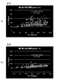
- the relationship between the reaction time T1 and the deflection angle ⁇ can be obtained by linearly approximating a graph in which the deflection angle ⁇ is the horizontal axis and the reaction time T1 is the vertical axis. That is, by approximating this graph linearly, an approximate expression (that is, an approximate line such as a regression line or a least-squares line) indicating the relationship between the reaction time T1 and the deflection angle ⁇ can be obtained.
- the method for deriving the approximate expression by linear approximation of the graph is not particularly limited, and various known methods can be employed.
- the position is a position where it is difficult to find the ARO, that is, a dark spot.
- the dark spot determination function 15 has a function of determining a dark spot with reference to an approximate line obtained by linear approximation of a graph plotting the ARO position and reaction time. In this case, since the difference in reaction time depending on the display position of the ARO can be corrected, the dark spot can be determined more accurately.
- the declination angle ⁇ can be obtained from the distance from the reference position BP to the peripheral position SP and the viewing distance.
- a graph may be formed using the distance from the reference position BP to the peripheral position SP. That is, even when a graph with the horizontal axis representing the distance from the reference position BP to the peripheral position SP and the vertical axis representing the reaction time T1 is linearly approximated, the relationship between the reaction time T1 and the distance is shown by linearly approximating the graph. An approximate expression can be obtained. Therefore, it may have a function of judging a dark spot with reference to this approximate expression.
- declination angle ⁇ and the distance from the reference position BP to the peripheral position SP correspond to the offset information of the inspection target referred to in the claims.
- the obtained data is separated into a linear part (that is, a non-dark spot part) and a dark spot part (hereinafter referred to as a dark spot candidate) by clustering.
- Clustering can be performed by a known method.
- a non-dark spot portion and a dark spot candidate can be separated using an EM algorithm, a K-means method, or the like.
- an approximate line such as a regression line or a least-squares line for the non-dark spot portion is derived by the same method as the method for calculating the approximate expression described above.
- This approximate straight line can be derived by the same method as the method for calculating the approximate expression described above, but is not particularly limited.
- a dark spot separation line is derived.
- the dark spot separation line can be derived using various methods. For example, a line that is parallel to the approximate straight line and that passes between data separated into dark spot candidates and data separated into non-dark spot candidates is defined as a dark spot separation line. Can do.
- the dark spot separation line is a line parallel to the approximate straight line and can satisfy any of the following conditions. 1) Among the straight lines parallel to the approximate straight line passing through the data in the dark spot determination area and the data classified as the dark spot candidates, the one having the smallest intercept with the time axis 2) The data classified as the non-dark spot candidates Of the straight lines parallel to the approximate straight line that passes, the one that is below the straight line obtained by the method of 1) and has the largest intercept with the time axis
- the dark spot determination area is set as described above, and the area where the Marriott blind spot is assumed to be located is located in that area, the dark spot separation line is obtained and the reaction is more effective than the dark spot separation line. If it is determined that a slow spot is a dark spot, the dark spot can be obtained with high accuracy.
- the dark spot separation line is adopted by the method 2), the dark spot can be obtained more accurately.
- the range of the region (exclusion region) excluded from the region for obtaining the dark spot is not particularly limited, and may be set as appropriate according to the characteristics of the device of the display unit 2. For example, if the display unit 2 is an HMD screen, only the pixels located at the outermost peripheral edge may be set as the exclusion region. In other devices, a plurality of pixels (for example, about 2 to 5 pixels) from the outer periphery may be excluded.
- the dark spot of one eye can be obtained based on the difference between the result measured with both eyes and the result measured with one eye. That is, when examining with both eyes, since the dark point of one eye is supplemented with the information of the other eye, it can be determined that the position where a different result is obtained is a dark spot. Therefore, the dark spot determination function 15 may compare the data of each position measured with both eyes and the data of each position measured with one eye and determine a position with a difference as a dark spot. .
- a pre-stimulation indicating the center of the screen (reference position) is displayed for 500 msec.
- a non-stimulated screen (a screen on which nothing is displayed) for 500 msec.
- Display ARO at the reference position 4)
- the ARO at the reference position is deleted and the ARO is displayed at the peripheral position.
- the ARO at the peripheral position is deleted and the non-stimulus screen is displayed for 1000 msec.
- Display device IO-DATA LCD-MF222FBR-T Number of pixels: 1920 (H) x 1080 (V) Pixel pitch: 0.24825 (H) x 0.24825 (V) Display area: 476.64mm (H) ⁇ 268.11mm (V) Display color: 16.77 million colors Viewing angle: 160 ° up / down / 170 ° left / right Maximum brightness: 260cd / m 2 Response speed: 5ms Luminance (cd / m 2 ): White part 140.8, Black part 3.3 Michelson contrast: 0.954 (ARO) Vertical and horizontal size: 12pixel x 12pixel (Notch size: 4pixel)
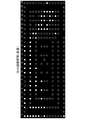
- the position where the dark spot is measured that is, the position where the ARO is displayed on the display device is 405 points obtained by dividing the screen into 27 parts in the height direction and 15 parts in the width direction (see FIG. 5).
- ARO was displayed in a 250-point display pattern in which the display density around the Marriott blind spot was increased so that the Marriott blind spot could be reliably detected out of 405 points.
- the dark spot was determined based on an approximate line obtained by linear approximation of a graph in which the horizontal axis is the declination ⁇ and the vertical axis is the reaction time T1. In other words, a position where the reaction time T1 is largely deviated from the approximate line (deviation is 500 ms or more) was determined as a dark spot.
- the experiment was conducted with 16 sighted people aged 18-24 years.
- the environment of the room in which the experiment was performed was a bright room, and the viewing distance (distance from the subject's face to the display device) was fixed at 50 cm on the chin rest.
- the experiment was performed with the right eye and both eyes in the state of the naked eye (in the case of correction with contact lenses or glasses). In the measurement of the right eye, the left eye was covered with gauze.
- FIGS. An example of the results is shown in FIGS. As shown in FIG. 6, in normal subjects, the reaction time was distributed in the vicinity of the approximate line. It was confirmed that the dark spots of the subject estimated from the approximate line were concentrated in the vicinity of the Marriott blind spot (FIG. 7).
- the visual field inspection method of the present invention can be used as an inspection method that can easily perform the inspection while maintaining the required accuracy and can determine the disease.
- the method for separating the dark spots was changed to confirm that the dark spots could be separated more appropriately.
- the same measurement as in Example 1 was performed on 32 sighted people aged 21 to 25 years, except for the following points. Note that a head mounted display HMZ-T3 manufactured by SONY was used as the display device, and a joystick was used as the input device.
- the measurement result data was separated into dark spot candidates and non-dark spot portions by clustering using the EM algorithm. After that, after obtaining a regression line of the non-dark spot portion, a dark spot separation line was derived.
- the dark spot separation line those satisfying the following two conditions were derived, and the dark spot discrimination between them was compared. 1) Among the straight lines parallel to the approximate straight line passing through the data in the dark spot determination area and the data classified as the dark spot candidates, the one having the smallest intercept with the time axis 2) The data classified as the non-dark spot candidates Of the straight lines that are parallel to the approximate straight line that passes through, the one that is below the straight line obtained by the method of 1) and has the largest intercept with respect to the time axis.
- the dark spot determination area is assumed to have a Marriott blind spot. (See FIG. 10B).
- the average dark spot detection rate was determined by the ratio of dark spot candidates included in the display positions included in the dark spot determination area.
- the average accuracy was obtained from the ratio of the display positions determined as dark spots that were included in the dark spot determination area.
- the method of 1) was compared with the test results of Humphrey perimeter. As shown in FIGS. 12 and 13, it can be confirmed that the result of the method 1) is almost the same as the inspection result of the Humphrey perimeter. That is, by adopting the method of the present invention, it was confirmed that the dark spot could be detected with the same degree of accuracy as the Humphrey perimeter while being a simple inspection.
- the visual field measurement apparatus of the present invention is suitable for an apparatus for measuring a dark spot used for determining diseases such as glaucoma, retinitis pigmentosa, diabetic retinopathy, retinal detachment, and macular degeneration.
- the visual acuity test target of the present invention is suitable as an inspection target for testing the minimum separation threshold.
Landscapes
- Health & Medical Sciences (AREA)
- Life Sciences & Earth Sciences (AREA)
- Engineering & Computer Science (AREA)
- Medical Informatics (AREA)
- Surgery (AREA)
- Biophysics (AREA)
- Biomedical Technology (AREA)
- Heart & Thoracic Surgery (AREA)
- Physics & Mathematics (AREA)
- Molecular Biology (AREA)
- Ophthalmology & Optometry (AREA)
- Animal Behavior & Ethology (AREA)
- General Health & Medical Sciences (AREA)
- Public Health (AREA)
- Veterinary Medicine (AREA)
- Signal Processing (AREA)
- Eye Examination Apparatus (AREA)
Abstract
Description
また、検査結果として得られる最小分離閾を網膜解像度と一致させることができ、自動計測や本発明の視野計測方法や視野計測装置に適した視力検査視標を提供することを目的とする。
第1発明の視野計測方法は、検査視標を表示部に順次表示させて視野を測定する方法であって、前記表示部の中央に設けられた基準位置に検査視標を表示させる基準視標表示工程と、該基準視標表示工程で表示された検査視標を認識したことを被験者に入力させる基準入力工程と、該基準入力工程において検査視標を認識したことが入力されると、前記基準位置と異なる位置に検査視標を表示させる周辺視標表示工程と、該周辺視標表示工程で表示された検査視標を認識したことを被験者に入力させる周辺入力工程と、を備えており、前記基準視標表示工程から前記周辺入力工程までを順次繰り返し実行し、前記周辺視標表示工程において検査視標が表示されてから前記周辺入力工程において被験者が入力するまでの反応時間を測定することを特徴とする。
第2発明の視野計測方法は、第1発明において、前記基準視標表示工程において表示される検査視標が、視力を検査する検査視標であり、前記基準視標表示工程では、前記検査視標の向きを被験者に入力させることを特徴とする。
第3発明の視野計測方法は、第1または第2発明において、前記周辺視標表示工程において表示される検査視標が、視力を検査する検査視標であり、前記周辺視標表示工程では、前記検査視標の向きを被験者に入力させるようになっており、前記周辺入力工程において被験者が入力した向きと前記周辺視標表示工程において表示された検査視標の向きが不一致となる割合が所定の値以上となった場合、または、前記周辺入力工程において被験者が入力した向きと前記周辺視標表示工程において表示された検査視標の向きが一致した場合であって前記反応時間が所定の時間以上となった場合に、該周辺位置を暗点と判断することを特徴とする。
第4発明の視野計測方法は、第3発明において、前記周辺視標表示工程において表示された検査視標のオフセット情報を横軸とし前記反応時間を縦軸として前記反応時間をプロットしたグラフを線形近似して得られる近似線を基準として、暗点を判断することを特徴とする。
第5発明の視野計測方法は、第4発明において、前記近似線を、暗点候補を除いたデータを利用して形成し、前記暗点候補に基づいて前記近似線と平行な暗点分離線を算出し、前記暗点候補のうち、前記暗点分離線よりも反応時間が遅いものを暗点と判断することを特徴とする。
第6発明の視野計測方法は、第5発明において、前記暗点候補のうち、マリオット盲点に位置するデータで暗点判別線を算出することを特徴とする。
第7発明の視野計測方法は、第1乃至第6発明のいずれかにおいて、前記基準位置に大きさの異なる視力を検査する検査視標を表示して、検査視標が表示されてから被験者が検査視標の方向を入力するまでの反応時間を測定し、検査視標の大きさと反応時間との関係に基づいて視野検査に使用する検査視標の大きさを決定することを特徴とする。
第8発明の視野計測方法は、第1乃至第7発明のいずれかにおいて、前記検査視標が、AROであることを特徴とする。
(視野計測装置)
第9発明の視野計測装置は、検査視標を表示する表示部と、該表示部に表示された検査視標を認識したことを被験者に入力させる入力部と、前記表示部に前記検査視標を表示させる位置およびタイミングを制御する表示制御部と、を備えており、該表示制御部は、前記表示部における基準位置に検査視標を表示させる基準視標表示機能と、前記表示部において、前記基準位置と異なる周辺位置に検査視標を表示させる周辺視標表示機能と、前記入力部からの信号に基づいて、前記基準視標表示機能と前記周辺視標表示機能を切り換える表示切換機能と、前記周辺視標表示機能によって前記検査視標を表示させてから、前記入力部に被験者が入力するまでの時間を測定する反応時間測定機能と、を備えていることを特徴とする。
第10発明の視野計測装置は、第9発明において、前記基準視標表示機能によって前記表示部における基準位置に表示される検査視標が、視力を検査する検査視標であり、前記入力部は、前記基準視標表示機能によって前記表示部における基準位置に表示された検査視標を認識した被験者に、前記検査視標の向きを入力させる構成となっていることを特徴とする。
第11発明の視野計測装置は、第9または第10発明において、前記周辺視標表示機能によって前記表示部における基準位置に表示される検査視標が、視力を検査する検査視標であり、前記入力部は、前記周辺視標表示機能によって前記表示部における基準位置に表示された検査視標を認識した被験者に、前記検査視標の向きを入力させる構成となっており、前記表示制御部は、記入力部への入力に基づいて暗点を判断する暗点判断機能を有しており、該暗点判断機能は、前記周辺位置に検査視標を表示させた際に前記入力部に入力された向きと前記周辺視標表示機能によって表示された前記周辺視標表示機能で表示した検査視標の向きが不一致となる割合が所定の値以上となった場合、または、前記周辺位置に検査視標を表示させた際に前記入力部に入力された向きと前記周辺視標表示機能で表示された検査視標の向きが一致した場合であって前記反応時間測定機能によって測定された測定時間が所定の時間以上となった場合に、前記周辺位置を暗点と判断する暗点判断機能を有していることを特徴とする。
第12発明の視野計測装置は、第11発明において、前記暗点判断機能は、前記周辺視標表示機能によって表示された検査視標のオフセット情報を横軸とし前記反応時間を縦軸として前記測定された反応時間をプロットしたグラフを線形近似して得られる近似線を基準として、暗点を判断する機能を有することを特徴とする。
第13発明の視野計測装置は、第12発明において、前記暗点判断機能は、前記近似線を暗点候補を除いたデータを利用して形成して、前記暗点候補に基づいて前記近似線と平行な暗点分離線を算出し、前記暗点候補のうち、前記暗点分離線よりも反応時間が遅いものを暗点と判断する機能を有することを特徴とする。
第14発明の視野計測装置は、第13発明において、前記暗点判断機能は、前記暗点候補のうち、マリオット盲点に位置するデータで暗点判別線を算出する機能を有することを特徴とする。
第15発明の視野計測装置は、第9乃至第14発明のいずれかにおいて、前記表示制御部は、前記基準位置および前記周辺位置に表示する検査視標の大きさを決定する視標サイズ決定機能を備えており、該視標サイズ決定機能は、前記基準位置に大きさの異なる視力を検査する検査視標を表示して、該検査視標が表示されてから被験者が該検査視標の方向を入力するまでの反応時間を測定する反応時間測定機能と、該反応時間測定機能が測定した反応時間と前記検査視標の大きさとの関係に基づいて視野検査に使用する検査視標の大きさを決定するサイズ決定機能を有していることを特徴とする。
第16発明の視野計測装置は、第9乃至第15発明のいずれかにおいて、前記検査視標が、AROであることを特徴とする。
(視力検査視標)
第17発明の視力検査視標は、最小分離閾の検査に使用される検査視標であって、互いに平行に設けられた一対の平行線と、該一対の平行線における互いに対向する端縁間を連結する一本の連結線と、から形成されており、前記一対の平行線は、同じ長さに形成されており、前記連結線は、前記一対の平行線と直交するように設けられており、前記一対の平行線の線幅、前記一対の平行線間の隙間の幅、および、前記連結線の線幅が、全て同じ長さになるように形成されていることを特徴とする。
第18発明の視力検査視標は、第17発明において、前記検査視標は、前記一対の平行線の長さと、前記一対の平行線の外縁間の距離が同じ長さとなるように形成されていることを特徴とする。
第19発明の視力検査視標は、第17または第18発明において、前記一対の平行線の長さと線幅の比が、2:1~5:1となるように調整されていることを特徴とする。
第1発明によれば、簡便かつ短時間の検査でマリオット盲点や暗点を正確に計測することができる。すると、緑内障や網膜色素変性症、糖尿病性網膜症、網膜剥離、黄斑変性などの疾患の早期発見や各疾患の進行度の評価・確定に寄与することができる。
第2発明によれば、被験者の視線を確実に基準位置に向けさせることができるので、検査精度を高めることができる。
第3発明によれば、暗点を正常と判断する判断ミスを少なくすることができるので、暗点を精度よく検出できる。
第4発明によれば、検査視標の表示位置による反応時間の差を補正できるので、暗点をより正確に判断することができる。
第5発明によれば、暗点候補のデータを使用して暗点判別線を形成するので、暗点を判断する精度を高くできる。
第6発明によれば、確実に暗点であるマリオット盲点のデータを使用して暗点判別線を形成するので、暗点を判断する精度をさらに高くできる。
第7発明によれば、視野検査に使用する検査視標の大きさを適切な大きさにできるので、反応時間を安定化することができる。したがって、検査視標を使用した視野検査の検査精度を向上することができる。
第8発明によれば、被験者による検査視標の認識を、被験者の実際の視力にあった状態とすることができるので、検査精度を高くすることができる。
(視野計測装置)
第9発明によれば、簡便かつ短時間の検査でマリオット盲点や暗点を正確に計測することができる。すると、緑内障や網膜色素変性症、糖尿病性網膜症、網膜剥離、黄斑変性などの疾患の早期発見や各疾患の進行度の評価・確定に寄与することができる。
第10発明によれば、被験者の視線を確実に基準位置に向けさせることができるので、検査精度を高めることができる。
第11発明によれば、暗点を正常と判断する判断ミスを少なくすることができるので、暗点を精度よく検出できる。
第12発明によれば、検査視標の表示位置による反応時間の差を補正できるので、暗点をより正確に判断することができる。
第13発明によれば、暗点候補のデータを使用して暗点判別線を形成するので、暗点を判断する精度を高くできる。
第14発明によれば、確実に暗点であるマリオット盲点のデータを使用して暗点判別線を形成するので、暗点を判断する精度をさらに高くできる。
第15発明によれば、視野検査に使用する検査視標の大きさを適切な大きさにできるので、反応時間を安定化することができる。したがって、検査視標を使用した視野検査の検査精度を向上することができる。
第16発明によれば、被験者による検査視標の認識を、被験者の実際の視力にあった状態とすることができるので、検査精度を高くすることができる。しかも、検査視標が曲線部分を有しないので、検査視標の表示を待つ時間を短くできるので検査時間を短縮できる。さらに、表示ミスなどによる検査漏れなどが生じないので、視野検査を自動化することが可能となる。
(視力検査視標)
第17~第19発明によれば、網膜解像度と一致した最小分離閾を得ることができる。しかも、曲線部分を有しないので、デジタル表示する際に、正確かつ高速に検査視標を表示させることができる。したがって、視力検査を自動化することが可能となる。
まず、本発明の視野測定方法や視野測定装置に使用される視力検査視標(以下、ARO(Accurate Resolution Optotype)という)を説明する。この本発明の視力検査視標が、特許請求の範囲にいうAROである。
まず、縞模様を使用して、縞模様として認識できる最小縞幅を測定した場合、その最小縞幅は網膜解像度にほぼ一致する。この縞模様について、空間周波数スペクトルを分析すると、空間周波数のピークが得られる。このピークとなる空間周波数(ピーク周波数)が、被験者が最も判別しやすい空間周波数、言い換えれば、縞模様を用いて検出される、被験者が認識できる最小縞幅となる。
一方、AROの空間周波数スペクトルを分析した場合、本来判別すべき空間周波数(つまり切欠きの周波数)でピークを有しており、同じ線幅の縞模様のピーク周波数でピークを有している。つまり、AROの視力検査では、被験者の網膜解像度を適切に検査できると考えられる。
さらに、AROは視力検査用の視標にとどまらず、他の視機能検査である視野検査(後述する)に組み込むことで各々の検査の精度を高めることが可能である。
図2に示すように、AROは、互いに平行に設けられた一対の平行線A1,A2を備えている。この一対の平行線A1,A2は、同じ長さに形成されており、その互いに対向する端縁(図2(A)では左側の端部)が、連結線A3によって連結されている。この連結線A3は、一対の平行線A1,A2に直交するように設けられている。つまり、AROは、カタカナのコの字状(アルファベットであれば角張ったU字状)に形成されている。しかも、AROは、一対の平行線A1,A2の線幅と、一対の平行線A1,A2間の隙間の幅(つまり切欠きAgの幅)、および、連結線A3の線幅が、全て同じ長さになるように形成されている。かかる形状に形成されているので、AROは上述したような効果を得ることができる。
上述した視力検査視標(ARO)を使用すれば、後述するような検査装置によって、視野検査、具体的には視野内に暗点が存在するか否かの検査を迅速かつ簡便に実施することができる。例えば、従来から使用されている視野検査装置では、検査に際し、視線の移動を固定しなければならず、被験者の顔を固定しかつ視線を固定しなければならなかった。加えて、検査の際には、外部光の影響を除くために、被験者の顔の前面全体を覆った状態で検査しなければならなかった。さらに、検査を適切に実施するためには、検査技師が装置の操作や検査ミスの監視をしなければならなかった。しかし、上述した視力検査視標を使用した本実施形態の検査装置であれば、被験者の顔などを拘束する必要がなく、また、外部光の影響を考慮しなくてもよくなる。すると、被験者の顔を覆う器具等も不要になるので、装置を簡素化でき、専用の装置がなくても検査が可能になるという利点も得られる。そして、被験者だけで測定を実施しても検査精度を維持できるので、被験者だけでなく検査技師の負担も軽減できるという利点も得られる。
以下、上述した視力検査視標を使用した視野検査装置1を説明する。
図1に示すように、視野検査装置1は、表示部2と、入力部3と、記憶部4と、表示制御部10と、を備えている。この視野検査装置1では、表示制御部10によってARO(検査視標)を表示部2に表示させる位置が変化するようになっている。そして、表示されたAROの切欠きAgがどの位置にあるか(つまりAROの向き)を入力部3から入力させる構成を採用している。
なお、視野検査装置1が表示する検査視標は、AROに限られず、他の検査視標を使用することもできる。例えば、ランドルト環や被験者の母語となる文字等を使用することができる。しかし、AROを検査視標として使用すれば、被験者による検査視標の認識を、被験者の実際の視力にあった状態とすることができるので、検査精度を高くすることができる。
表示部2は、表示制御部10や外部からの指示に基づいて、表示制御部10や外部から供給される情報を表示できるものである。具体的には、表示制御部10からの指示に基づいて、AROを所定の位置(後述する基準位置BPや周辺位置SP)に表示させることができるものである。
入力部3は、表示部2に表示されたAROの向きを被験者に入力させるためのものである。この入力部3は、AROの向き、具体的には、AROの切欠きAgが上下左右の4方向のどの位置に配置されているかを被験者が入力できるものである。例えば、キーボードやジョイスティック、マウス等の入力装置を入力部3として採用することができる。キーボードのカーソルキーを使用すれば、入力装置の操作に対する習熟度の影響を少なくすることができるので、好ましい。また、ジョイスティックを使用した場合にも、ジョイスティックを切欠きAgの方向(上下は前後になる)に倒すだけであるので、入力装置の操作に対する習熟度の影響を少なくすることができる。
記憶部4は、表示制御部10と接続されており、表示制御部10の各機能から情報が送信され、その情報を記憶する機能を有している。例えば、表示制御部10の周辺視標表示機能12から送信される、表示させたAROやAROを表示させた位置に関する情報と、入力部3に入力された方向、後述する反応時間と、を関連付けて記憶する機能を有している。
表示制御部10は、表示部2にAROを表示させる位置およびタイミングを制御する機能を有するものである。つまり、表示制御部10は、入力部3からの信号に基づいて、AROの表示を制御するものである。この表示制御部10は、基準視標表示機能11と、周辺視標表示機能12と、表示切換機能13と、反応時間測定機能14と、暗点判断機能15と、を備えている。
基準視標表示機能11は、表示部2の基準位置BPにAROを表示させる機能を有するものである。具体的には、基準視標表示機能11は、表示切換機能13から指令が送信されると、基準位置BPの位置に関する情報と基準位置BPに表示させるAROの情報を含む情報(基準表示情報)を表示部2に送信して、AROを表示部2に表示させる機能を有している。
周辺視標表示機能12は、表示部2の基準位置BP以外の場所(周辺位置SP)にAROを表示させる機能を有するものである。具体的には、周辺視標表示機能12は、表示切換機能13から指令が送信されると、周辺位置SPの位置に関する情報と周辺位置SPに表示させるAROの情報を含む情報(周辺表示情報)を、表示部2に送信して、AROを表示部2に表示させる機能を有している。
表示切換機能13は、入力部3からの入力に基づいて、検査視標を表示させる機能を、基準視標表示機能11と周辺視標表示機能12との間で切り換える機能を有するものである。具体的には、入力部3からの入力に基づいて、基準視標表示機能11と周辺視標表示機能12のいずれを作動させるかを決定する機能を有するものである。
反応時間測定機能14は、周辺視標表示機能12によってAROが表示された後、入力部3にAROの向きが入力されるまでの時間を計測する機能を有している。
暗点判断機能15は、反応時間測定機能14によって測定された反応時間に基づいて、周辺位置SPが暗点か否かを判断する機能を有している。加えて、暗点判断機能15は、その周辺位置SPを暗点と判断した場合、暗点情報を、周辺位置SPの情報や反応時間に関連付けて記憶部4に記憶させる機能を有している。
基準位置BPや周辺位置SPに表示させるAROの大きさはとくに限定されない。しかし、検査精度を向上させる上では、検査直前に被験者の認識能力を測定し、その結果に基づいて、表示部2に表示させるAROの大きさを決定することが望ましい。つまり、表示制御部10が、AROの大きさを決定する視標サイズ決定機能16を有していることが望ましい。
反応時間は、通常、AROが小さいほど遅く、AROが大きくなると速くなる。しかし、AROが一定以上の大きさになるとAROが大きくなっても反応速度がほぼ一定になる(図10(A)の丸囲み部分参照)。したがって、視標サイズ決定機能16では、測定された反応時間が一定になる最小の大きさを検査視標とする。
つぎに、上記視野検査装置1を使用した視野検査を説明する。
なお、以下の例では、基準位置BPおよび周辺位置SPに、同じ大きさのAROを表示させて検査を行う場合を説明する。
検査スタートは、被験者がキーボードのキーを押すこと等でスタートする。
なお、検査スタートの指示はどのような方法を採用してもよい。
なお、入力部3から入力されたAROの向きが間違っている場合には、表示切換機能13は基準視標表示機能11から周辺視標表示機能12への切り替えは行わず、基準視標表示機能11による表示を継続する。
上記例では、表示制御部10が、基準視標表示機能11等の複数の独立した機能を有している場合を説明した。しかし、表示制御部10は、一つの表示機能だけを設けて、この表示機能に、上述した基準視標表示機能と周辺視標表示機能、表示切換機能の全ての機能を具備させてもよい。例えば、入力部3からの入力に応じて、基準位置BPと周辺位置SPで交互にAROを表示させるようにしてもよい。
また、視野検査装置1は、検査結果をマップ(暗点マップ)にして表示するマップ形成機能を有していてもよい。暗点マップとして、結果を表示させれば、視覚的に暗点の分布を把握できるので、疾患の診断に利用しやすくなる。
暗点判断機能15による暗点か否かの判断は、上述したような方法で判断してもよいが、以下のような判断方法を使用すれば、より精度よく暗点を判断することができる。
(1)視標発見時間(a)
(2)視線移動(サッケード)時間(b)
(3)ギャップ判別時間(c)
(4)キー押下運動時間(d)
T1=視標発見時間(a) + 視線移動(サッケード)時間(b) + ギャップ判別時間(c) + キー押下運動時間(d)
なお、グラフを線形近似して近似式を導出する方法は、とくに限定されず、公知の種々の方法を採用できる。
また、上述した近似式を得る際に、暗点のデータを含めて近似式を形成すると、得られた近似式が本来の暗点が無いデータだけから得られる近似式からずれてしまう可能性がある。したがって、暗点をより精度よく検出する上では、以下の処理を実施することが望ましい。
暗点分離線を導出する際に、暗点であることが確実であるマリオット盲点を利用することが好ましい。この場合、暗点分離線を、上記近似直線と平行な線であって、以下のいずれかの条件を満たすものとすることができる。
1)暗点判定エリア内のデータかつ暗点候補に分類されたデータを通る近似直線に平行な直線のうち、時間軸との切片が最も小さいもの
2)非暗点候補に分類されたデータを通る近似直線に平行な直線のうち、1)の方法で求めた直線より下で、かつ、時間軸との切片が最も大きいもの
ここで、表示部2の周縁部では、画像のゆがみなどが発生しやすく、被験者がAROを視認しにくくなっているので、暗点でない場合でも、反応時間が長くなり、暗点とご判断される可能性がある。したがって、表示部2の周縁部に位置する領域については、暗点を求める領域から除外してもよい。かかる暗点を求める領域から除外する領域(除外領域)の範囲はとくに限定されず、表示部2の機器の特性に応じて、適宜設定すればよい。例えば、表示部2がHMD画面であれば、最外周縁に位置する画素だけを除外領域とすればよい。また、他の機器であれば、外周縁から複数の画素(例えば2~5画素程度)を除外領域としてもよい。
さらに簡便な方法としては、両眼で測定された結果と片眼で測定された結果の差に基づいて、片眼の暗点を求めることもできる。つまり、両眼で検査した場合、片方の眼の暗点を他方の眼の情報で補っているため、両者で異なった結果が出ている位置は暗点であると判断できる。したがって、暗点判断機能15は、両眼で測定された各位置のデータと片眼で測定された各位置のデータを比較して、差異がある位置を暗点と判断するようにしてもよい。
1)画面中心(基準位置)を示す前置刺激(ARO)を500msec表示する。
2)無刺激画面(何も表示されていない画面)を500msec表示する。
3)基準位置にAROを表示する。
4)AROの向きが入力されると、基準位置のAROを消して、周辺位置にAROを表示する。
5)AROの向きが入力されると、周辺位置のAROを消して、無刺激画面を1000msec表示する。
6)上記2~5を250回繰り返して、実験を終了する。
(表示装置)
液晶ディスプレイ:IO-DATA製LCD-MF222FBR-T
画素数:1920(H)×1080(V)
画素ピッチ:0.24825(H)×0.24825(V)
表示面積:476.64mm(H)×268.11mm(V)
表示色:1677万色
視野角度:上下160°/左右170°
最大輝度:260cd/m2
応答速度:5ms
輝度(cd/m2):白部140.8,黒部3.3
マイケルソンコントラスト: 0.954
(ARO)
縦横のサイズ:12pixel×12pixel(切り欠きサイズ:4pixel)
実験を実施した部屋の環境は明室とし、視距離(被験者の顔から表示装置までの距離)は、顎台で50cmに固定した。
なお、実験では、裸眼(コンタクトレンズやメガネで矯正されている場合にはその状態)の状態で、右目と両目で行った。なお、右目の測定の際には、左目はガーゼで覆った。
図6に示すように、正常な被験者では、反応時間がほぼ近似線近傍に分布していた。近似線から推定される被験者の暗点は、ほぼマリオット盲点近傍に集中していることが確認された(図7)。
なお、表示装置にはヘッドマウントディスプレイSONY製HMZ-T3を使用し、入力装置にはジョイスティックを使用した。
その上で、非暗点部分の回帰直線を求めた後、暗点分離線を導出した。
1)暗点判定エリア内のデータかつ暗点候補に分類されたデータを通る近似直線に平行な直線のうち、時間軸との切片が最も小さいもの
2)非暗点候補に分類されたデータを通る近似直線に平行な直線のうち、1)の方法で求めた直線より下で、かつ、時間軸との切片が最も大きいもの
なお、暗点判定エリアは、マリオット盲点が存在することが想定される領域を含むように設定した(図10(B)参照)。
また、平均精度(適合率)は、暗点と判定された表示位置のうち暗点判定エリアに含まれていた割合によって求めた。
図11(A)に示すように、1)の方法と2)の方法では、暗点分離線にズレが生じており、平均暗点検出率および平均精度にもズレが生じている(図11(B))。このことから、暗点分離線を導出する方法として、いずれの方法を採用するかによって、暗点と判断されるものにずれが生じることが確認された。
図12、図13に示すように、1)の方法の結果は、ハンフリー視野計の検査結果とほぼ同等の結果が得られていることが確認できる。つまり、本発明の方法を採用することによって、簡便な検査でありつつ、ハンフリー視野計と同程度の精度で暗点を検出できる可能性があることが確認された。
また、本発明の視力検査視標は、最小分離閾を検査するための検査視標に適している。
2 表示部
3 入力部
4 記憶部
10 表示制御部
11 基準視標表示機能
12 周辺視標表示機能
13 表示切替機能
14 反応時間測定機能
15 暗点判断機能
16 視標サイズ決定機能
16a 反応時間測定機能
16b サイズ決定機能
Claims (19)
- 検査視標を表示部に順次表示させて視野を測定する方法であって、
前記表示部の中央に設けられた基準位置に検査視標を表示させる基準視標表示工程と、
該基準視標表示工程で表示された検査視標を認識したことを被験者に入力させる基準入力工程と、
該基準入力工程において検査視標を認識したことが入力されると、前記基準位置と異なる位置に検査視標を表示させる周辺視標表示工程と、
該周辺視標表示工程で表示された検査視標を認識したことを被験者に入力させる周辺入力工程と、を備えており、
前記基準視標表示工程から前記周辺入力工程までを順次繰り返し実行し、前記周辺視標表示工程において検査視標が表示されてから前記周辺入力工程において被験者が入力するまでの反応時間を測定する
ことを特徴とする視野計測方法。 - 前記基準視標表示工程において表示される検査視標が、視力を検査する検査視標であり、
前記基準視標表示工程では、前記検査視標の向きを被験者に入力させる
ことを特徴とする請求項1記載の視野計測方法。 - 前記周辺視標表示工程において表示される検査視標が、視力を検査する検査視標であり、
前記周辺視標表示工程では、前記検査視標の向きを被験者に入力させるようになっており、
前記周辺入力工程において被験者が入力した向きと前記周辺視標表示工程において表示された検査視標の向きが不一致となる割合が所定の値以上となった場合、
または、
前記周辺入力工程において被験者が入力した向きと前記周辺視標表示工程において表示された検査視標の向きが一致した場合であって前記反応時間が所定の時間以上となった場合に、該周辺位置を暗点と判断する
ことを特徴とする請求項1または2記載の視野計測方法。 - 前記周辺視標表示工程において表示された検査視標のオフセット情報を横軸とし前記反応時間を縦軸として前記反応時間をプロットしたグラフを線形近似して得られる近似線を基準として、暗点を判断する
ことを特徴とする請求項3記載の視野計測方法。 - 前記近似線を、暗点候補を除いたデータを利用して形成し、
前記暗点候補に基づいて前記近似線と平行な暗点分離線を算出し、
前記暗点分離線よりも反応時間が遅いものを暗点と判断する
ことを特徴とする請求項4記載の視野計測方法。 - 前記暗点候補のうち、マリオット盲点に位置するデータを利用して暗点判別線を算出する
ことを特徴とする請求項5記載の視野計測方法。 - 前記基準位置に大きさの異なる視力を検査する検査視標を表示して、検査視標が表示されてから被験者が検査視標の方向を入力するまでの反応時間を測定し、
検査視標の大きさと反応時間との関係に基づいて視野検査に使用する検査視標の大きさを決定する
ことを特徴とする請求項1乃至6のいずれかに記載の視野計測方法。 - 前記検査視標が、AROである
ことを特徴とする請求項1乃至7のいずれかに記載の視野計測方法。 - 検査視標を表示する表示部と、
該表示部に表示された検査視標を認識したことを被験者に入力させる入力部と、
前記表示部に前記検査視標を表示させる位置およびタイミングを制御する表示制御部と、を備えており、
該表示制御部は、
前記表示部における基準位置に検査視標を表示させる基準視標表示機能と、
前記表示部において、前記基準位置と異なる周辺位置に検査視標を表示させる周辺視標表示機能と、
前記入力部からの信号に基づいて、前記基準視標表示機能と前記周辺視標表示機能を切り換える表示切換機能と、
前記周辺視標表示機能によって前記検査視標を表示させてから、前記入力部に被験者が入力するまでの時間を測定する反応時間測定機能と、を備えている
ことを特徴とする視野計測装置。 - 前記基準視標表示機能によって前記表示部における基準位置に表示される検査視標が、視力を検査する検査視標であり、
前記入力部は、
前記基準視標表示機能によって前記表示部における基準位置に表示された検査視標を認識した被験者に、前記検査視標の向きを入力させる構成となっている
ことを特徴とする請求項10記載の視野計測装置。 - 前記周辺視標表示機能によって前記表示部における基準位置に表示される検査視標が、視力を検査する検査視標であり、
前記入力部は、
前記周辺視標表示機能によって前記表示部における基準位置に表示された検査視標を認識した被験者に、前記検査視標の向きを入力させる構成となっており、
前記表示制御部は、
前記入力部への入力に基づいて暗点を判断する暗点判断機能を有しており、
該暗点判断機能は、
前記周辺位置に検査視標を表示させた際に前記入力部に入力された向きと前記周辺視標表示機能によって表示された前記周辺視標表示機能で表示した検査視標の向きが不一致となる割合が所定の値以上となった場合、
または、
前記周辺位置に検査視標を表示させた際に前記入力部に入力された向きと前記周辺視標表示機能で表示された検査視標の向きが一致した場合であって前記反応時間測定機能によって測定された測定時間が所定の時間以上となった場合に、
前記周辺位置を暗点と判断する暗点判断機能を有している
ことを特徴とする請求項9または10記載の視野計測装置。 - 前記暗点判断機能は、
前記周辺視標表示機能によって表示された検査視標のオフセット情報を横軸とし前記反応時間を縦軸として前記測定された反応時間をプロットしたグラフを線形近似して得られる近似線を基準として、暗点を判断する機能を有する
ことを特徴とする請求項11記載の視野計測装置。 - 前記暗点判断機能は、
前記近似線を暗点候補を除いたデータを利用して形成して、前記暗点候補に基づいて前記近似線と平行な暗点分離線を算出し、前記暗点候補のうち、前記暗点分離線よりも反応時間が遅いものを暗点と判断する機能を有する
ことを特徴とする請求項12記載の視野計測装置。 - 前記暗点判断機能は、
前記暗点候補のうち、マリオット盲点に位置するデータを利用して暗点判別線を算出する機能を有する
ことを特徴とする請求項13記載の視野計測装置。 - 前記表示制御部は、
前記基準位置および前記周辺位置に表示する検査視標の大きさを決定する視標サイズ決定機能を備えており、
該視標サイズ決定機能は、
前記基準位置に大きさの異なる視力を検査する検査視標を表示して、該検査視標が表示されてから被験者が該検査視標の方向を入力するまでの反応時間を測定する反応時間測定機能と、
該反応時間測定機能が測定した反応時間と前記検査視標の大きさとの関係に基づいて視野検査に使用する検査視標の大きさを決定するサイズ決定機能を有している
ことを特徴とする請求項9乃至14のいずれかに記載の視野計測装置。 - 前記検査視標が、AROである
ことを特徴とする請求項9乃至15のいずれかに記載の視野計測装置。 - 最小分離閾の検査に使用される検査視標であって、
互いに平行に設けられた一対の平行線と、
該一対の平行線における互いに対向する端縁間を連結する一本の連結線と、から形成されており、
前記一対の平行線は、同じ長さに形成されており、
前記連結線は、前記一対の平行線と直交するように設けられており、
前記一対の平行線の線幅、前記一対の平行線間の隙間の幅、および、前記連結線の線幅が、全て同じ長さになるように形成されている
ことを特徴とする視力検査視標。 - 前記検査視標は、
前記一対の平行線の長さと、前記一対の平行線の外縁間の距離が同じ長さとなるように形成されている
ことを特徴とする請求項17記載の視力検査視標。 - 前記一対の平行線の長さと線幅の比が、2:1~5:1となるように調整されている
ことを特徴とする請求項17または18記載の視力検査視標。
Priority Applications (4)
| Application Number | Priority Date | Filing Date | Title |
|---|---|---|---|
| EP16833036.3A EP3332692B1 (en) | 2015-08-03 | 2016-08-02 | Visual field measuring method and visual field measuring apparatus |
| CN201680044774.1A CN107847122B (zh) | 2015-08-03 | 2016-08-02 | 视野计测方法、视野计测装置和视力检查视标 |
| US15/750,179 US10687700B2 (en) | 2015-08-03 | 2016-08-02 | Visual field measuring method, visual field measuring apparatus, and optotype |
| JP2017533085A JP6230086B2 (ja) | 2015-08-03 | 2016-08-02 | 視野計測方法、視野計測装置および視力検査視標 |
Applications Claiming Priority (2)
| Application Number | Priority Date | Filing Date | Title |
|---|---|---|---|
| JP2015-153722 | 2015-08-03 | ||
| JP2015153722 | 2015-08-03 |
Publications (1)
| Publication Number | Publication Date |
|---|---|
| WO2017022757A1 true WO2017022757A1 (ja) | 2017-02-09 |
Family
ID=57943073
Family Applications (1)
| Application Number | Title | Priority Date | Filing Date |
|---|---|---|---|
| PCT/JP2016/072647 Ceased WO2017022757A1 (ja) | 2015-08-03 | 2016-08-02 | 視野計測方法、視野計測装置および視力検査視標 |
Country Status (5)
| Country | Link |
|---|---|
| US (1) | US10687700B2 (ja) |
| EP (1) | EP3332692B1 (ja) |
| JP (1) | JP6230086B2 (ja) |
| CN (1) | CN107847122B (ja) |
| WO (1) | WO2017022757A1 (ja) |
Cited By (11)
| Publication number | Priority date | Publication date | Assignee | Title |
|---|---|---|---|---|
| WO2019172285A1 (ja) * | 2018-03-07 | 2019-09-12 | 株式会社クリュートメディカルシステムズ | 視覚検査装置及び視覚検査プログラム |
| WO2020137544A1 (ja) * | 2018-12-25 | 2020-07-02 | 国立大学法人愛媛大学 | 視野検査装置 |
| CN111867444A (zh) * | 2018-03-19 | 2020-10-30 | 克瑞托医疗系统股份有限公司 | 视野检查装置、视野检查装置的控制方法以及视野检查程序 |
| WO2021256100A1 (ja) | 2020-06-16 | 2021-12-23 | 株式会社ファインデックス | 視野検査装置 |
| WO2022044548A1 (ja) | 2020-08-25 | 2022-03-03 | 株式会社ファインデックス | 可視判定システム及び視野検査装置 |
| JP2022073154A (ja) * | 2020-10-30 | 2022-05-17 | 株式会社ニデック | 検眼装置 |
| JP2023036436A (ja) * | 2021-09-02 | 2023-03-14 | 株式会社ニデック | 視標呈示装置及び視標呈示プログラム |
| WO2023042869A1 (ja) * | 2021-09-14 | 2023-03-23 | 株式会社ナックイメージテクノロジー | コントラスト感度検査装置、光学素子評価装置、コントラスト感度検査方法、光学素子評価方法 |
| WO2023119913A1 (ja) | 2021-12-24 | 2023-06-29 | 株式会社ファインデックス | 視野検査装置 |
| JP2024078290A (ja) * | 2022-11-29 | 2024-06-10 | 正彦 仲井 | 視覚検査並びに改善訓練システム及びその活用方法 |
| JP2025034786A (ja) * | 2023-08-31 | 2025-03-13 | 株式会社Qdレーザ | 視野検査装置、視野検査方法およびプログラム |
Families Citing this family (15)
| Publication number | Priority date | Publication date | Assignee | Title |
|---|---|---|---|---|
| US10628481B2 (en) * | 2016-11-17 | 2020-04-21 | Ebay Inc. | Projecting visual aspects into a vector space |
| WO2019124449A1 (ja) * | 2017-12-22 | 2019-06-27 | 株式会社ビジュアル・テクノロジー研究所 | 視機能検査および光学特性算出システム |
| DE102018106125B4 (de) | 2018-03-16 | 2019-09-26 | Carl Zeiss Vision International Gmbh | Vorrichtung und Verfahren zum Erfassen eines Gesichtsfelds einer ein Skotom aufweisenden Person |
| US11813106B2 (en) * | 2018-05-29 | 2023-11-14 | National University Corporation Ehime University | Image processing device, and image processing method utilizing time-series computed tomography (CT) images |
| CN108937839A (zh) * | 2018-08-24 | 2018-12-07 | 周丰超 | 一种视标及其应用的三分视力表 |
| WO2020050497A1 (ko) * | 2018-09-04 | 2020-03-12 | 주식회사 엠투에스 | 가상현실 기반의 시야검사 방법 및 시스템 |
| KR102295587B1 (ko) * | 2019-01-15 | 2021-08-31 | 주식회사 엠투에스 | 가상현실 기반의 시야검사 방법 및 시스템 |
| CN109875498B (zh) * | 2019-02-19 | 2021-07-30 | 温州医科大学 | 一种基于反应时间的动态视力测量系统 |
| US12533073B2 (en) * | 2019-09-30 | 2026-01-27 | Albert Einstein College Of Medicine | Systems and methods for testing of multisensory integration effects |
| WO2021263133A1 (en) * | 2020-06-25 | 2021-12-30 | Thomas Jefferson University | Systems and methods for blind spot tracking |
| KR102876125B1 (ko) * | 2020-07-15 | 2025-10-27 | 에씰로 앙터나시오날 | 사람의 시력을 평가하는 방법 및 시스템 |
| CN111956177B (zh) * | 2020-08-17 | 2022-01-11 | 中山大学中山眼科中心 | 一种用于量化视物变形的系统 |
| CN113273957A (zh) * | 2021-04-12 | 2021-08-20 | 瀛乾邦实业控股(深圳)有限公司 | 基于vr技术的视力检测筛查系统 |
| WO2023283217A2 (en) * | 2021-07-07 | 2023-01-12 | Warby Parker Inc. | Systems and methods for vision test and uses thereof |
| KR102596560B1 (ko) * | 2023-03-21 | 2023-10-31 | 주식회사 셀리코 | 시각장애환자 (망막색소 변성증, 황반반변성증, 녹내장)을 위한 증강현실 장치 및 알고리즘 |
Citations (4)
| Publication number | Priority date | Publication date | Assignee | Title |
|---|---|---|---|---|
| JP2002315725A (ja) * | 2001-04-20 | 2002-10-29 | Menicon Co Ltd | 視力検査表 |
| JP2009240638A (ja) * | 2008-03-31 | 2009-10-22 | Chiba Univ | 視機能評価装置 |
| JP2011161122A (ja) * | 2010-02-15 | 2011-08-25 | Kansai Univ | 視野検査システム |
| JP2014087660A (ja) * | 2013-11-08 | 2014-05-15 | Tomohiro Tsuta | 閾値上且つ一定の強度を有する視覚刺激に対する反応時間に基づく視野視覚機能測定装置 |
Family Cites Families (12)
| Publication number | Priority date | Publication date | Assignee | Title |
|---|---|---|---|---|
| JPH07313457A (ja) | 1994-05-24 | 1995-12-05 | Canon Inc | 視標装置 |
| JP2002000565A (ja) | 2000-06-20 | 2002-01-08 | Akio Nakagawa | 視力表 |
| JP2002172089A (ja) | 2000-12-07 | 2002-06-18 | Akio Nakagawa | 中心外視力測定用視力表 |
| TWI289437B (en) * | 2002-01-04 | 2007-11-11 | Vision Optic Co Ltd | Optometry apparatus, optometry method, optometry server and computer readable recording medium |
| JP4288128B2 (ja) | 2003-09-30 | 2009-07-01 | 株式会社ニデック | 眼科装置 |
| JP4734052B2 (ja) | 2005-07-14 | 2011-07-27 | 興和株式会社 | 視野計 |
| CN1827035A (zh) * | 2006-04-06 | 2006-09-06 | 赵阳 | 减少视野检查中被检者主观误差的方法和相关装置 |
| CN100579444C (zh) * | 2008-08-29 | 2010-01-13 | 天津医科大学 | 四点视野检测装置 |
| US9492344B2 (en) * | 2009-08-03 | 2016-11-15 | Nike, Inc. | Unified vision testing and/or training |
| US9433346B2 (en) * | 2011-11-21 | 2016-09-06 | Gobiquity, Inc. | Circular preferential hyperacuity perimetry video game to monitor macular and retinal diseases |
| US10736502B2 (en) * | 2013-09-02 | 2020-08-11 | Ocuspecto Oy | Testing and determining a threshold value |
| JP5826902B2 (ja) | 2014-09-05 | 2015-12-02 | 株式会社クリュートメディカルシステムズ | 視覚検査装置及び視覚検査プログラム |
-
2016
- 2016-08-02 EP EP16833036.3A patent/EP3332692B1/en active Active
- 2016-08-02 CN CN201680044774.1A patent/CN107847122B/zh active Active
- 2016-08-02 WO PCT/JP2016/072647 patent/WO2017022757A1/ja not_active Ceased
- 2016-08-02 US US15/750,179 patent/US10687700B2/en active Active
- 2016-08-02 JP JP2017533085A patent/JP6230086B2/ja active Active
Patent Citations (4)
| Publication number | Priority date | Publication date | Assignee | Title |
|---|---|---|---|---|
| JP2002315725A (ja) * | 2001-04-20 | 2002-10-29 | Menicon Co Ltd | 視力検査表 |
| JP2009240638A (ja) * | 2008-03-31 | 2009-10-22 | Chiba Univ | 視機能評価装置 |
| JP2011161122A (ja) * | 2010-02-15 | 2011-08-25 | Kansai Univ | 視野検査システム |
| JP2014087660A (ja) * | 2013-11-08 | 2014-05-15 | Tomohiro Tsuta | 閾値上且つ一定の強度を有する視覚刺激に対する反応時間に基づく視野視覚機能測定装置 |
Non-Patent Citations (1)
| Title |
|---|
| See also references of EP3332692A4 * |
Cited By (18)
| Publication number | Priority date | Publication date | Assignee | Title |
|---|---|---|---|---|
| JP7290916B2 (ja) | 2018-03-07 | 2023-06-14 | 株式会社クリュートメディカルシステムズ | 視覚検査装置及び視覚検査プログラム |
| JP2019154464A (ja) * | 2018-03-07 | 2019-09-19 | 株式会社クリュートメディカルシステムズ | 視覚検査装置及び視覚検査プログラム |
| WO2019172285A1 (ja) * | 2018-03-07 | 2019-09-12 | 株式会社クリュートメディカルシステムズ | 視覚検査装置及び視覚検査プログラム |
| CN111867444A (zh) * | 2018-03-19 | 2020-10-30 | 克瑞托医疗系统股份有限公司 | 视野检查装置、视野检查装置的控制方法以及视野检查程序 |
| WO2020137544A1 (ja) * | 2018-12-25 | 2020-07-02 | 国立大学法人愛媛大学 | 視野検査装置 |
| JP2020099556A (ja) * | 2018-12-25 | 2020-07-02 | 国立大学法人愛媛大学 | 視野検査装置 |
| WO2021256100A1 (ja) | 2020-06-16 | 2021-12-23 | 株式会社ファインデックス | 視野検査装置 |
| WO2022044548A1 (ja) | 2020-08-25 | 2022-03-03 | 株式会社ファインデックス | 可視判定システム及び視野検査装置 |
| JP2022073154A (ja) * | 2020-10-30 | 2022-05-17 | 株式会社ニデック | 検眼装置 |
| JP7623567B2 (ja) | 2020-10-30 | 2025-01-29 | 株式会社ニデック | 検眼装置 |
| JP2023036436A (ja) * | 2021-09-02 | 2023-03-14 | 株式会社ニデック | 視標呈示装置及び視標呈示プログラム |
| JP7725951B2 (ja) | 2021-09-02 | 2025-08-20 | 株式会社ニデック | 視標呈示装置及び視標呈示プログラム |
| WO2023042869A1 (ja) * | 2021-09-14 | 2023-03-23 | 株式会社ナックイメージテクノロジー | コントラスト感度検査装置、光学素子評価装置、コントラスト感度検査方法、光学素子評価方法 |
| WO2023119913A1 (ja) | 2021-12-24 | 2023-06-29 | 株式会社ファインデックス | 視野検査装置 |
| JP2024078290A (ja) * | 2022-11-29 | 2024-06-10 | 正彦 仲井 | 視覚検査並びに改善訓練システム及びその活用方法 |
| JP7650079B2 (ja) | 2022-11-29 | 2025-03-24 | 正彦 仲井 | 視覚検査並びに改善訓練システム及びその活用方法 |
| JP2025034786A (ja) * | 2023-08-31 | 2025-03-13 | 株式会社Qdレーザ | 視野検査装置、視野検査方法およびプログラム |
| JP7668556B2 (ja) | 2023-08-31 | 2025-04-25 | 株式会社Qdレーザ | 視野検査装置、視野検査方法およびプログラム |
Also Published As
| Publication number | Publication date |
|---|---|
| US20180296084A1 (en) | 2018-10-18 |
| EP3332692A4 (en) | 2019-08-07 |
| CN107847122A (zh) | 2018-03-27 |
| EP3332692A1 (en) | 2018-06-13 |
| JPWO2017022757A1 (ja) | 2017-11-30 |
| EP3332692B1 (en) | 2020-09-23 |
| CN107847122B (zh) | 2020-08-11 |
| JP6230086B2 (ja) | 2017-11-15 |
| US10687700B2 (en) | 2020-06-23 |
Similar Documents
| Publication | Publication Date | Title |
|---|---|---|
| JP6230086B2 (ja) | 視野計測方法、視野計測装置および視力検査視標 | |
| JP5421146B2 (ja) | 視野検査システム | |
| JP6774136B2 (ja) | 自動視力診断の方法およびシステム | |
| JP5727191B2 (ja) | 検眼装置 | |
| JP2019069180A (ja) | 主観的距離計測に基づく眼の屈折異常の測定のためのシステムおよび方法 | |
| CN109008939B (zh) | 检查装置以及检查方法 | |
| CN110604541B (zh) | 双眼平衡检测系统及其检测方法 | |
| AU2020209870B2 (en) | System and method for digital measurement of stereo vision | |
| JP2014533587A5 (ja) | ||
| JP5161002B2 (ja) | 視野計、視野測定プログラム、及びそのプログラムを格納した記憶媒体 | |
| JP6606264B1 (ja) | 視野検査装置 | |
| JP6892540B2 (ja) | 眼科装置 | |
| WO2014010664A1 (ja) | 視野計 | |
| JP2016116542A (ja) | 視覚検査装置、視覚検査方法、視覚検査プログラム及び同プログラムを格納した記録媒体 | |
| JP7369001B2 (ja) | 眼科装置 | |
| KR20120132801A (ko) | 대비감도 측정장치 및 방법 | |
| JP7575752B1 (ja) | 視野検査装置、視野検査方法およびプログラム | |
| JP5852187B2 (ja) | 視野計 | |
| JP2008029731A (ja) | 眼科装置 | |
| KR20230148702A (ko) | 중심 시야의 결손 및 변형 검사 방법 및 장치 | |
| JP2023146675A (ja) | 眼科装置 | |
| WO2023119913A1 (ja) | 視野検査装置 | |
| JP2020195692A (ja) | 視機能検査システム及び視機能検査アプリケーションソフト |
Legal Events
| Date | Code | Title | Description |
|---|---|---|---|
| 121 | Ep: the epo has been informed by wipo that ep was designated in this application |
Ref document number: 16833036 Country of ref document: EP Kind code of ref document: A1 |
|
| ENP | Entry into the national phase |
Ref document number: 2017533085 Country of ref document: JP Kind code of ref document: A |
|
| WWE | Wipo information: entry into national phase |
Ref document number: 15750179 Country of ref document: US |
|
| NENP | Non-entry into the national phase |
Ref country code: DE |
|
| WWE | Wipo information: entry into national phase |
Ref document number: 2016833036 Country of ref document: EP |