WO2017033247A1 - Système de traitement et procédé de commande de robot - Google Patents
Système de traitement et procédé de commande de robot Download PDFInfo
- Publication number
- WO2017033247A1 WO2017033247A1 PCT/JP2015/073634 JP2015073634W WO2017033247A1 WO 2017033247 A1 WO2017033247 A1 WO 2017033247A1 JP 2015073634 W JP2015073634 W JP 2015073634W WO 2017033247 A1 WO2017033247 A1 WO 2017033247A1
- Authority
- WO
- WIPO (PCT)
- Prior art keywords
- processing
- robot
- arm
- unit
- calibration
- Prior art date
- Legal status (The legal status is an assumption and is not a legal conclusion. Google has not performed a legal analysis and makes no representation as to the accuracy of the status listed.)
- Ceased
Links
Images




Classifications
-
- B—PERFORMING OPERATIONS; TRANSPORTING
- B25—HAND TOOLS; PORTABLE POWER-DRIVEN TOOLS; MANIPULATORS
- B25J—MANIPULATORS; CHAMBERS PROVIDED WITH MANIPULATION DEVICES
- B25J13/00—Controls for manipulators
Definitions
- the present invention relates to a processing system and a robot control method.
- Patent Document 1 describes a measurement system that measures the height position, planar position, and posture of a load with a laser marker and a CCD camera provided on a robot hand and causes the hand to perform a picking operation.
- Patent Document 2 describes a scanning operation in which one or a plurality of points of the edge position of each side of a workpiece is measured by a position detection sensor mounted on a robot.
- Patent Document 3 describes that three points (P1, P2, P3) on two orthogonal sides of the work object are measured by a contact position detection probe provided in the robot.
- the robot arm may have multiple joints and may be able to approach the device with multiple different postures. In such a case, it should be possible to approach the same point ideally regardless of the posture of the device, but in reality, the backlash of the gears constituting each joint and the deflection of the robot arm The approach point may be shifted depending on the posture of the robot arm. For this reason, even if the position of the device is measured in advance, the approach point of the robot arm when performing work using the device may deviate from a desired point.
- the object of the present invention is to provide a processing system and a robot control method capable of performing precise work by a robot arm.
- a processing system includes a robot that performs processing on a processing target with one or a plurality of arms, a position measurement sensor provided in the arm, and a robot control device that controls at least the robot.
- the robot control device uses a position measurement sensor to measure a position of a device used when the robot performs processing on the processing target, and a position measurement unit.
- a processing unit that moves the arm with respect to a position and performs processing on the processing target, and the processing unit includes a posture of the arm in processing on the processing target, and a position of the device by the position measuring unit. The arm is controlled so that a difference from the posture of the arm in the position measurement becomes small.
- the robot control device may include a calibration unit that calibrates a relationship between the position of the processing target in the device and the position of the arm.
- the robot control device is determined to cause the calibration unit to perform calibration, and the determination unit to determine whether or not to perform calibration.
- it may include an insertion unit that inserts the calibration performed by the calibration unit before performing the process on the processing target.
- the determination unit may determine whether or not to cause the calibration unit to perform calibration according to the type of processing for the processing target.
- the determination unit may determine whether to cause the calibration unit to perform calibration according to at least one of the passage of time and the number of processes. .
- the determination unit may determine whether or not to cause the calibration unit to perform calibration according to a standby time before performing the process on the processing target. .
- the determination unit may determine that the calibration unit performs calibration when the robot stops due to an error.
- the determination unit may determine that the calibration unit performs calibration when maintenance is performed on at least one of the robot and the device. .
- the device has two sides in a direction intersecting with each other in a plan view, and the position measuring unit is configured to detect each of the two sides of the device by the position measuring sensor.
- the edge position may be measured at a plurality of locations.
- the robot control device configures coordinates representing the position of the processing target in the device based on the positions of the edges of the plurality of positions measured by the position measurement unit. You may have a coordinate composition part to do.
- the position measurement unit may measure the position of the device located above the processing position where the processing on the processing target is performed by the position measurement sensor. It may be done.
- the apparatus further includes a fixture provided with an extending portion that fixes the device and extends upward, and the position measuring unit includes the extension of the fixture. You may make it measure the position by the said position measurement sensor about the upper surface of a part.
- a method for controlling a robot wherein a position measurement sensor provided in one or more arms of the robot determines a position of a device used when the robot performs processing on a processing target. Measuring and moving the arm with reference to the measured position of the device, and adjusting the arm so that a difference between the posture of the moved arm and the posture of the arm in measuring the position of the device is reduced. And control the processing target by the robot.
- FIG. 1 is a configuration block diagram showing a physical configuration of a robot control apparatus according to an embodiment of the present invention. It is a functional block diagram of a robot control device, a position measurement sensor, and a robot according to an embodiment of the present invention. It is a perspective view which shows the external appearance of the tube rack which concerns on embodiment of this invention. It is a top view which shows two sides of the tube rack measured by the position measurement sensor which concerns on embodiment of this invention. It is a figure which shows the apparatus coordinate system comprised from the point measured by the position measurement sensor which concerns on embodiment of this invention. It is a perspective view which shows the fixing tool which concerns on embodiment of this invention. It is a flowchart about judgment of the necessity of calibration by the judgment part concerning the embodiment of the present invention. It is a flowchart about the control method of the robot which concerns on embodiment of this invention.
- FIG. 1 is a schematic diagram showing a physical configuration of a processing system 200 according to an embodiment of the present invention.
- the processing system 200 includes at least a robot controller 1 that controls the robot 3.
- the robot control device 1 itself may be a dedicated device, but here is realized using a general computer. That is, in a commercially available computer, the computer is used as the robot control device 1 by executing a computer program that causes the computer to operate as the robot control device 1.
- a computer program is generally provided in the form of application software, and is used by being installed in a computer.
- the application software may be provided by being recorded on an appropriate computer-readable information recording medium such as a CD-ROM, DVD-ROM, or may be provided through various information communication networks such as the Internet. Alternatively, it may be realized by so-called cloud computing in which the function is provided by a server at a remote place through an information communication network.
- the processing system 200 includes a position measurement sensor 2 provided in the first arm 3 a of the robot 3.
- the position measurement sensor 2 is a sensor for specifying the position of the measurement target with respect to the arm of the robot 3.
- the position measurement sensor 2 can detect a planar or three-dimensional position of a measurement object alone or with the movement of an arm.
- the position measurement sensor 2 is a laser sensor that irradiates a measurement target with laser light and measures the distance to the measurement target.
- the position measurement sensor 2 may not be a laser sensor, and for example, position detection using a camera capable of shooting a moving image or a still image, an ultrasonic sensor, a contact sensor, a magnetic sensor, or the like may be employed.
- a laser sensor as the position measurement sensor 2 it is possible to measure the distance to the measurement object in a non-contact and high accuracy.
- the processing system 200 includes a robot 3 that performs processing on a processing target with one or a plurality of arms.
- the robot 3 according to the present embodiment is an articulated robot, and performs processing on a processing target by the first arm 3a and the second arm 3b.
- the first arm 3a and the second arm 3b are arms that can perform processing on a processing target in a plurality of different postures. Specifically, it is an arm having joints of 7 axes or more.
- the processing target is a target to be subjected to a series of tests, culture, and amplification in the fields of biochemistry, biology, and biotechnology, and refers to, for example, cultured cells and drugs.
- the processing target may be other than that, and may be a part to be processed / assembled / disassembled such as welding or bolt tightening by the robot 3 or a package to be transported such as transport or palletizing. .
- the robot 3 can operate a laboratory instrument (not shown or illustrated) such as gripping and operating the pipette 4 accommodated in the pipette rack with a hand provided at the tip of the first arm 3a.
- the robot 3 holds the microtube 6 stored in the tube rack 5 with a hand provided at the tip of the second arm 3b, and moves the microtube 6 from the tube rack 5 to the vortex mixer 9, the centrifuge 10, or the like.
- Various containers (not shown or illustrated) can be moved, such as being moved.
- the robot 3 holds the pipette 4 with the hand provided at the tip of the first arm 3a and attaches the tip prepared in the tip rack 7 to the tip of the pipette 4 when sucking or injecting the chemical solution.
- the chip rack 7 is fixed to the work table by a fixture 8.
- a vortex mixer 9 and a centrifuge 10 are included.
- the processing system 200 may include a rack for storing Petri dishes, a magnet rack, and the like.
- the robot 3 according to the present embodiment is a double-arm robot, and the robot 3 includes a first arm 3a and a second arm 3b.
- One or more arms included in the processing system 200 are, for example, a plurality of arms. May be separately provided and controlled so as to operate cooperatively by the robot control device 1.
- the processing system 200 uses a plurality of coordinate systems in order to define a point P on the space that the tip of the arm of the robot 3 approaches.
- One is a robot coordinate system S R associated with the robot 3.
- Robot coordinate system S R is a coordinate system based on the robot 3, the origin in this example is a left-handed orthogonal coordinate system in the center of the robot 3.
- An arbitrary point is represented as coordinates (X, Y, Z) with reference to the robot 3.
- it can represent the tip of the coordinates of the robot arm 3.
- Coordinates of point P represented by the robot coordinate system S R (X, Y, Z ) is the angle of the joint of a plurality of (N) constituting the arm ( ⁇ 1, ⁇ 2, ... , ⁇ N) corresponding to .
- the angles ( ⁇ 1 , ⁇ 2 ,..., ⁇ N ) of a plurality of joints constituting the arm are referred to as arm postures.
- the degree of freedom (number of joints) of the arm is 7 degrees or more
- the angles of the joints of the arm ( ⁇ 1 , ⁇ 2) ,..., ⁇ N ) are not uniquely determined and have redundancy.
- the origin of the robot coordinate system S R is may be set to a point other than the center of the robot, the type of coordinate system used may be other than the Cartesian coordinate system.
- an equipment coordinate system SD associated with equipment used when the robot 3 performs processing on the processing target, such as the tube rack 5, is also used.
- the equipment coordinate system S D1 associated with the tube rack 5 is a left-handed orthogonal coordinate system whose origin is at the upper corner of the tube rack 5, and coordinates (x 1 , y representing the point P with respect to the tube rack 5 as a reference. 1 , z 1 ).
- the equipment coordinate system SD1 By using the equipment coordinate system SD1 , the accommodation location of the microtube 6 included in the tube rack 5 can be simply expressed.
- the device coordinate system SD a coordinate system (spherical coordinates, cylindrical coordinates, etc.) suitable for the device can be set for each device.
- the device coordinate system SD may be configured and stored in advance on a simulator executed in the robot control device 1 or a computer placed outside.
- the instrument coordinate system SD in addition to the instrument coordinate system S D1 associated with the tube rack 5, the instrument coordinate system S D2 associated with the tip rack 7 and the centrifuge 10 are associated.
- the device coordinate system SD3 is shown. These will be described in detail later.
- the processing system 200 causes the robot 3 to conduct experiments in the fields of biochemistry, biology, and biotechnology
- the contents of the experiment can vary, and the equipment used for each experiment can be changed or the arrangement of the equipment can be changed.
- the tip attached to the tip of the pipette 4 is placed over the wall surface of the microtube 6 to inject the chemical solution, or the trace amount of the chemical solution contained in the microtube 6 is removed.
- precise work such as suction is required, and high-precision arm control may be required.
- the device coordinate system SD is configured on the simulator, the point that the arm actually approaches may be shifted due to the influence of the backlash of the gears constituting each joint of the arm, the deflection of the arm, or the like. . Therefore, in order to perform a precise work, it is desirable to configure the device coordinate system SD in a form in which an influence such as arm deflection is folded.
- the arm posture is redundant, but the robot control apparatus 1 according to the present embodiment is subject to processing.
- the arm is controlled so that the difference between the posture of the arm in the process for the above and the posture of the arm in the measurement of the position of the device by the position measurement sensor 2 becomes small.
- a small difference in arm posture means that a difference vector ( ⁇ processing) between an N-dimensional vector ⁇ process representing the arm posture during processing and an N-dimensional vector ⁇ measurement representing the arm posture during measurement. This means that the norm of ⁇ measurement )
- may be any as long as it can evaluate the difference in arm posture. For example,
- may be calculated as the sum of absolute values of the respective elements.
- the norm of the vector difference may be evaluated by weighting each vector element representing the angle of each joint.
- means that the norm value falls within the lower 25% of the possible values of the norm.
- the norm of the arm posture difference vector may be used instead of using the other evaluation function.
- the arm posture at the origin of the device coordinate system SD and the processing time are controlled by controlling the difference in arm posture between the processing time and the measurement time to be small.
- the difference between the position of the arm and the position of the arm becomes smaller, and the origin of the arm is adjusted in a manner in which the influence of backlash and deflection of each joint is folded. Therefore, according to the processing system 200 according to the present embodiment, the approach point of the arm is prevented from deviating from a desired point, the arm can be accurately aligned, and a precise work can be performed by the arm. it can. Even when the position of the device changes, the position of the device is accurately measured, and the arm can be accurately aligned with the device.
- the robot control apparatus 1 calibrates the relationship between the device coordinate system S D and the robot coordinate system S R.
- the relationship between the device coordinate system S D and the robot coordinate system S R, the position of the processing target in the apparatus, a relationship between the position of the arm, specifically, by the instrument coordinate system S D represented point P of coordinates (x, y, z), refers to the transformation matrix a for converting the robot coordinate system S P output coordinate points represented by R (X, Y, Z) on.
- the transformation matrix A is generally a 3 ⁇ 3 matrix and is a 6-degree-of-freedom matrix representing translation and rotation.
- Processing system 200 according to this embodiment, by precisely constitutes the instrument coordinate system S D, the relationship between the device coordinate system S D and the robot coordinate system S R, i.e. calibrating the transformation matrix A, by the arm It enables precise work.
- FIG. 2 is a block diagram showing a physical configuration of the robot control apparatus 1 according to the embodiment of the present invention.
- the configuration shown in FIG. 2 shows a general computer used as the robot control device 1, and includes a CPU (Central Processing Unit) 1a, a RAM (Random Access Memory) 1b, an external storage device 1c, and a GC (Graphics Controller).
- a CPU Central Processing Unit
- RAM Random Access Memory
- an external storage device 1c a GC (Graphics Controller).
- Id input device
- I / O Inpur / Output
- the external storage device 1c is a device capable of recording information statically such as an HDD (Hard Disk Drive) or an SSD (Solid State Drive).
- the signal from the GC 1d is output to a monitor 1h such as a flat panel display where the user visually recognizes the image and displayed as an image.
- the input device 1e is a device for a user to input information such as a keyboard, a mouse, and a touch panel, and the I / O 1f is an interface for the robot controller 1 to exchange information with an external device.
- FIG. 3 is a functional block diagram of the robot control device 1, the position measurement sensor 2, and the robot 3 according to the embodiment of the present invention. Note that the functional blocks shown here are shown paying attention to the functions of the robot control device 1 and the like, and there is not necessarily a one-to-one physical configuration corresponding to each functional block. Some functional blocks are realized by an information processing device such as the CPU 1a of the robot control device 1 executing specific software, and some functional blocks are stored in a specific storage area in an information storage device such as the RAM 1b of the robot control device 1. May be realized by being assigned.
- the robot control apparatus 1 has an input unit 20 that receives various inputs from the user.
- the robot control apparatus 1 includes an operation command generation unit 21 that generates an operation command that is a command for controlling the operation of the robot 3 based on an input received by the input unit 20.
- the robot control apparatus 1 includes an operation command storage unit 27 that stores electronic data of the generated and generated operation commands, and an operation command output that outputs the generated operation commands as an electronic file that can be read by the robot.
- Unit 28 and an operation command display unit 29 that forms electronic data of the operation command stored in the operation command storage unit 27 and displays it on the monitor 1h.
- the input unit 20 is normally configured by the input device 1e shown in FIG. 2, but when the robot control apparatus 1 is an application server used for cloud computing, the user's terminal on a remote terminal is used. This corresponds to the I / O 1f to which the operation information is input.
- the operation command generation unit 21 includes various functional blocks for generating operation commands. Although details will be described later when the operation command generation procedure is described, the operation command generation unit 21 according to the present embodiment is used by the position measurement sensor 2 when the robot 3 performs processing on the processing target.
- a position measurement unit 23 that measures the position of the device to be measured
- a processing unit 22 that moves the arm based on the measured position of the device and performs processing on the processing target, a position of the processing target in the device, and a position of the arm
- a calibration unit 24 that calibrates the relationship between
- the operation command generation unit 21 determines whether or not the calibration unit 24 performs calibration. When the determination unit 26 determines that calibration is to be performed, the calibration by the calibration unit 24 is performed. Are inserted before the processing on the processing target is performed.
- an operation command is a single job or a collection of jobs in which a plurality of jobs are combined, and is recognized as a unit for a processing target or a container that stores the processing target.
- the equipment used when the robot 3 performs processing on the processing target includes the pipette 4, the tube rack 5, the microtube 6, the tip rack 7, the fixture 8, and the vortex. It refers to the mixer 9 and the centrifuge 10. Needless to say, these are merely examples, and generally, other materials may be included. Any device included in the processing system 200 can be a device used when the robot 3 performs processing on a processing target.
- the position measurement unit 23 includes an edge measurement unit 23a, a coordinate configuration unit 23b, an upper measurement unit 23c, and a fixture measurement unit 23d.
- the edge measuring unit 23a causes the position measuring sensor 2 to measure the positions of the edges for each of the two sides of the device used when the robot 3 performs processing on the processing target.
- the coordinate configuration unit 23b configures coordinates representing the position of the processing target in the device based on the positions of the edges of the plurality of locations measured by the edge measurement unit 23a included in the position measurement unit 23.
- the upper measurement unit 23c causes the position measurement sensor 2 to measure the position of the device located above the processing position where the processing on the processing target is performed.
- the fixture measuring unit 23d fixes the device and causes the position measurement sensor 2 to measure the position of the upper surface of the extending portion of the fixture provided with the extending portion extending upward.
- the determination unit 26 includes a process type determination unit 26a, a time / number of times determination unit 26b, a standby determination unit 26c, an error determination unit 26d, and a maintenance determination unit 26e.
- the processing type determination unit 26a determines whether or not to cause the calibration unit 24 to perform calibration according to the type of processing for the processing target.
- the time / number of times determination unit 26b determines whether or not to cause the calibration unit 24 to perform calibration according to at least one of the passage of time and the number of processes.
- the standby determination unit 26c determines whether or not to cause the calibration unit 24 to perform calibration according to the standby time before performing the process on the processing target.
- the error determination unit 26d determines that the calibration unit 24 performs calibration when the robot 3 stops due to an error.
- the maintenance determination unit 26e determines that the calibration unit 24 performs calibration when maintenance is performed on at least one of the robot 3 and the device used when the robot 3 performs processing on the processing target.
- FIG. 4 is a perspective view showing an appearance of the tube rack 5 according to the embodiment of the present invention.
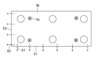
- FIG. 5 is a top view showing two sides of the tube rack 5 measured by the position measurement sensor 2 according to the embodiment of the present invention.
- the tube rack 5 includes a base 5a that is fixed to a work table with bolts, an upper plate 5b that has six holes for accommodating the microtubes 6, and a column 5c that connects the upper plate 5b to the base 5a.
- the tube rack 5 has a first side E1 and a second side E2 in a direction intersecting with each other in plan view.
- FIG. 1 first side E1 and a second side E2 in a direction intersecting with each other in plan view.
- the edge measuring unit 23a obtains the arm posture (angle of each joint) when the laser beam jumps across the edge of the upper plate 5b and the distance to the upper plate 5b measured by the laser sensor. From the posture of the arm at the edge of the edge, the planar position of the edge of the edge expressed in robot coordinates can be calculated, and the three-dimensional position of the edge of the edge is obtained together with the distance measured by the laser sensor. Can do.
- the edge measuring unit 23a causes the position measuring sensor 2 to measure the positions of the edges at a plurality of locations for each of the first side E1 and the second side E2 of the tube rack 5.
- the position of the edge is measured at six places on the first side E1, and the position of the edge is measured at four places on the second side E2.
- the number of measurement points increases, the influence of the error can be reduced.
- the number of measurement points is set in consideration of the balance between the two.
- three points on the device may be measured. For example, the corner points at both ends of the first side E1 of the tube rack 5 and the corner points of the second side E1.
- errors occur due to various factors in the measurement.
- the coordinates can be configured with higher accuracy than when the coordinates are configured by measuring three points of the device. As a result, the arm can be positioned more accurately.
- pillar 5c of the tube rack 5 which concerns on this embodiment is provided in the position away from the edge of the upper board 5b so that it may not interfere with the scanning of a laser sensor. Thereby, it is possible to prevent the laser sensor from erroneously detecting the step due to the support column 5c, and the position of the tube rack 5 can be measured smoothly.
- the processing position 6a where the processing for the processing target accommodated in the microtube 6 is performed is illustrated by an asterisk.
- the processing position is a position where the tip end of the pipette 4 is aligned.
- the upper measurement unit 23c causes the position measurement sensor 2 to measure the position of the device located above the processing position 6a.
- the upper plate 5b of the tube rack 5 is a part of the equipment (tube rack 5) located above the processing position 6a.
- the position of the arm at the time of measurement is closer to the position of the arm at the time of processing, and the position can be measured in a state where influences such as backlash and arm deflection are further reduced. it can. It is particularly advantageous to cause the position measurement sensor 2 to measure the position of the device located above the processing position 6a when the measurable range of the position measurement sensor 2 is limited. If the position of the base 5a is measured when the measurable range of the position measurement sensor 2 is limited, it is necessary to bring the position measurement sensor 2 close to the base 5a. This is because the posture may be bent downward from the posture of the arm.
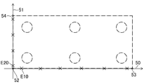
- FIG. 6 is a diagram showing a device coordinate system composed of points measured by the position measurement sensor 2 according to the embodiment of the present invention.
- the coordinate configuration unit 23b according to the present embodiment is based on a plurality of edge positions E10 of the first side E1 and a plurality of edge positions E20 of the second side E2 measured by the edge measurement unit 23a.
- the coordinates (device coordinates S D ) representing the position of the processing target in the tube rack 5 are configured.
- the coordinate configuration unit 23b calculates a straight line overlapping the first side E1 from the plurality of edge positions E10 with respect to the first side E1, and calculates the x-axis 50.
- the least square method can be adopted, but another algorithm may be adopted.
- the coordinate configuration unit 23b calculates a straight line overlapping the second side E2 from a plurality of edge positions E20 with respect to the second side E2, and calculates the y-axis 51. Then, the origin 52 of the device coordinates is calculated from the intersection 52 where the x-axis 50 and the y-axis 51 intersect and the height of the upper plate 5b measured by the position measurement sensor 2.
- the coordinates 53 of the end of the upper plate 5b in the x-axis 50 and the coordinates 54 of the end of the upper plate 5b in the y-axis 51 are determined.
- the device coordinate system SD1 is determined.
- the processing system 200 capable of precisely aligning the tool such as the pipette 4 is obtained.
- FIG. 7 is a perspective view showing the fixture 8 according to the embodiment of the present invention.
- the fixture 8 is an instrument for fixing the chip rack 7 to the work table.
- the fixture 8 and the chip rack 7 are relatively accurately aligned and fixed with screws or the like, and the fixture 8 and the work table are detachably fixed with bolts or the like.
- the device fixed by the fixture 8 may be other than the chip rack 7.
- the fixture 8 according to the present embodiment is provided with an extending portion 8a extending upward.
- the extending portion 8 a may be formed of the same material as the bolted portion of the fixture 8, and the upper surface is in a surface state suitable for measurement by the position measurement sensor 2.
- the position measurement sensor 2 is a laser sensor
- the upper surface of the extending portion 8a is a smooth surface.
- the fixture measuring unit 23 d causes the position measurement sensor 2 to measure the position of the upper surface of the extending portion 8 a of the fixture 8.
- the coordinate structure part 23b comprises apparatus coordinate system SD2 based on the position of the edge of the upper surface of the extending
- the difference between the posture of the arm when the position measurement sensor 2 performs measurement on the upper surface of the extending portion 8a and the posture of the arm when the tip rack 7 is attached to the pipette 4 is the base of the fixture 8 ( This is smaller than the difference between the posture of the arm when measuring the position of the lower plate portion to be bolted) and the posture of the arm when attaching the tip to the pipette 4 with respect to the tip rack 7.
- the fixture 8 having the extending portion 8a is particularly advantageous when the measurable range of the position measurement sensor 2 is limited.
- the posture of the arm at the time of measurement is the position of the arm at the time of processing. This is because the posture may be bent downward from the posture.
- the posture of the arm when measuring the upper surface of the extending portion 8a by the position measurement sensor 2 is close to the posture of the arm when performing processing using the device,
- the position can be measured in a state where the influence of backlash and arm deflection is further reduced. Therefore, the arm is positioned more accurately in the process using the device, and the accuracy of the process using the device is improved.
- a reference flat plate 11 is provided on the upper surface of the centrifuge 10.
- the position measurement unit 23 causes the position measurement sensor 2 to measure the position of the reference flat plate 11.
- the coordinate structure part 23b comprises apparatus coordinate system SD3 based on the position of the edge of the measured reference
- the reference flat plate 11 is provided when the device does not have an edge suitable for measurement, such as a rounded chamfered side of the device or a complicated shape.
- the position of the device By measuring the position of the flat plate 11, the position of the device can be indirectly measured. Since the position where the processing target is accommodated in the device and the position of the reference plate 11 are approximate, the difference in the posture of the arm during measurement and processing can be reduced, and the measurement can be performed accurately. Matching can be performed precisely.
- FIG. 8 is a flowchart for determining the necessity of calibration by the determination unit 26 according to the embodiment of the present invention.
- the processing type determination unit 26a of the determination unit 26 determines whether or not to cause the calibration unit 24 to perform calibration according to the type of processing for the processing target.
- the process type determination unit 26a determines that the calibration unit 24 performs calibration when the process for the processing target is a process using the pipette 4 (ST100). This is because the process using the pipette 4 is a process that requires particularly high precision and requires precise control of the arm.
- the processing type determination unit 26a may determine that the calibration unit 24 performs calibration when processing other than processing using the pipette 4 is performed. For example, when a drug sensitive to a physical impact is handled, the calibration unit 24 may be calibrated prior to processing so that the arm can be precisely controlled.
- the process type determination unit 26a it is possible to perform calibration in advance for a process that needs to control the arm with particularly high accuracy, and it is possible to perform a precise work by the arm. On the other hand, calibration can be omitted for a process that does not cause a problem even if the arm is controlled with relatively rough accuracy, and the working time can be shortened.
- the time / number of times determination unit 26b of the determination unit 26 determines whether or not to cause the calibration unit 24 to perform calibration according to at least one of the passage of time and the number of processes.
- the time / frequency determination unit 26b causes the calibration unit 24 to perform calibration when the robot 3 has not been operating for a long time (ST101). For example, when the robot 3 has not been operated for 24 hours or more, it may be determined that the calibration unit 24 performs calibration. As a result, when the robot 3 has not been operated for a long time, calibration is automatically performed, and a reduction in work accuracy can be prevented.
- the time / number of times determination unit 26b causes the calibration unit 24 to perform calibration when the accumulated number of times of processing for the processing target by the robot 3 is equal to or greater than a predetermined value (ST102). For example, when the robot 3 performs the process 1000 times or more without performing calibration by the calibration unit 24, it may be determined that the calibration unit 24 performs calibration. Thereby, when the robot 3 continues to operate for a long time (when the accumulated number of processes becomes equal to or greater than a predetermined value), the calibration is automatically performed, and a decrease in work accuracy can be prevented.
- a predetermined value ST102
- the standby determination unit 26c of the determination unit 26 determines whether or not to cause the calibration unit 24 to perform calibration according to the standby time before performing processing on the processing target.
- the standby determination unit 26c determines that the calibration unit 24 performs calibration when the standby time before performing the process on the processing target is 5 minutes or longer (ST103). It goes without saying that the waiting time serving as the threshold may be arbitrarily set by the user. As a result, calibration can be performed during the waiting time of the robot 3, and the working accuracy can be improved by effectively using the waiting time.
- the error determination unit 26d of the determination unit 26 determines that the calibration unit 24 performs calibration when the robot 3 stops due to an error.
- the error determination unit 26d determines that the calibration by the calibration unit 24 is performed when the robot 3 is urgently stopped due to a natural disaster or an accident, or when the robot 3 is urgently stopped by the user. (ST104).
- calibration is automatically performed when a shortage such as a natural disaster occurs, and even if the user does not always monitor the processing system 200, the accuracy of the work is reduced due to an unexpected situation. Is prevented.
- the maintenance determination unit 26e of the determination unit 26 determines that the calibration unit 24 performs calibration when the maintenance is performed on at least one of the robot 3 and the device.
- the robot 3 and equipment are arranged in a booth isolated from the outside.
- the maintenance determination unit 26e according to the present embodiment determines that maintenance has been performed on at least one of the robot 3 and the device when the booth where the robot 3 and the device are disposed is opened and closed, and performs calibration to the calibration unit 24. (ST105).
- the maintenance determination unit 26e may determine whether the calibration unit 24 performs calibration by detecting the presence or absence of maintenance using a sensor provided in the robot 3 or the device. Thus, calibration is automatically performed after maintenance that may change the state of the arm of the robot 3 or change the fixed position of the device, thereby preventing a reduction in work accuracy.
- the insertion unit 25 inserts calibration by the calibration unit 24 before performing processing on the processing target (ST106).
- the calibration unit 24 calibrates the relationship between the position of the processing target in the device and the position of the arm. That is, the calibration unit 24 acquires an instrument coordinate system S D structure based on a measurement by the position measurement unit 23, to calibrate the conversion matrix A between the device coordinate system S D and the robot coordinate system S R .
- the position of the processing target or device represented by the device coordinate system SD can be accurately read as the posture of the arm of the robot 3 (angle of each joint), and precise work by the arm is possible.
- calibration is automatically performed prior to the processing. It is possible to prevent misalignment in the alignment.
- the order of determination by the determination unit 26 described above is an example, and the priority of determination by the process type determination unit 26a, the time / number of times determination unit 26b, the standby determination unit 26c, the error determination unit 26d, and the maintenance determination unit 26e is: It may be set by the user.
- FIG. 9 is a flowchart of the robot control method according to the embodiment of the present invention.
- the position of the device used when the robot 3 performs processing on the processing target is determined by the position measurement sensor 2 provided in one or more arms of the robot 3. Measure (ST200).
- the arm is moved based on the measured position of the device, the arm is controlled so that the difference between the posture of the arm to be moved and the posture of the arm in the measurement of the position of the device becomes small. Processing is performed on the processing target (ST201).
- the arm posture at the origin of the device coordinate system SD is controlled by controlling so that the difference in arm posture between processing and measurement is small.
- the difference between the position of the arm and the position of the arm becomes smaller, and the origin of the arm is adjusted in a manner in which the influence of backlash and deflection of each joint is folded. For this reason, the approach point of the arm is prevented from deviating from a desired point, the arm can be accurately aligned, and a precise operation can be performed by the arm. Even when the position of the device changes, the position of the device is accurately measured, and the arm can be accurately aligned with the device.
Landscapes
- Engineering & Computer Science (AREA)
- Robotics (AREA)
- Mechanical Engineering (AREA)
- Manipulator (AREA)
Abstract
L'invention concerne un système de traitement, lequel système a un robot (3) pour soumettre une cible de traitement à un traitement à l'aide d'un ou de plusieurs bras, un capteur de mesure de position (2) disposé sur les bras, et un dispositif de commande de robot (1) pour, au moins, commander le robot, et dans lequel : le dispositif de commande de robot a une unité de mesure de position (23) pour mesurer, à l'aide du capteur de mesure de position, la position d'un dispositif devant être utilisé quand le robot soumet la cible de traitement au traitement, et a également une unité de traitement (22) pour déplacer les bras avec la position de dispositif mesurée comme référence, et effectuer le traitement de la cible de traitement ; et l'unité de traitement commande les bras de manière à réduire la différence entre l'orientation des bras pendant le traitement de la cible de traitement et l'orientation des bras lors de la mesure de la position du dispositif à l'aide de l'unité de mesure de position.
Priority Applications (2)
| Application Number | Priority Date | Filing Date | Title |
|---|---|---|---|
| PCT/JP2015/073634 WO2017033247A1 (fr) | 2015-08-21 | 2015-08-21 | Système de traitement et procédé de commande de robot |
| JP2017536088A JP6555351B2 (ja) | 2015-08-21 | 2015-08-21 | 処理システム及びロボットの制御方法 |
Applications Claiming Priority (1)
| Application Number | Priority Date | Filing Date | Title |
|---|---|---|---|
| PCT/JP2015/073634 WO2017033247A1 (fr) | 2015-08-21 | 2015-08-21 | Système de traitement et procédé de commande de robot |
Publications (1)
| Publication Number | Publication Date |
|---|---|
| WO2017033247A1 true WO2017033247A1 (fr) | 2017-03-02 |
Family
ID=58100163
Family Applications (1)
| Application Number | Title | Priority Date | Filing Date |
|---|---|---|---|
| PCT/JP2015/073634 Ceased WO2017033247A1 (fr) | 2015-08-21 | 2015-08-21 | Système de traitement et procédé de commande de robot |
Country Status (2)
| Country | Link |
|---|---|
| JP (1) | JP6555351B2 (fr) |
| WO (1) | WO2017033247A1 (fr) |
Cited By (8)
| Publication number | Priority date | Publication date | Assignee | Title |
|---|---|---|---|---|
| WO2019003401A1 (fr) * | 2017-06-29 | 2019-01-03 | 株式会社ソニー・インタラクティブエンタテインメント | Appareil de commande de robot, procédé de commande et programme de commande |
| CN110193832A (zh) * | 2019-03-29 | 2019-09-03 | 牧今科技 | 验证和更新机器人控制用相机校准的方法和控制系统 |
| CN110253629A (zh) * | 2019-04-12 | 2019-09-20 | 牧今科技 | 用于更新用于机器人控制的相机校准的方法和控制系统 |
| WO2020055801A1 (fr) | 2018-09-11 | 2020-03-19 | Becton, Dickinson And Company | Système de préparation d'échantillon robotique pour test de diagnostic avec apprentissage de position automatisé |
| JP2020040165A (ja) * | 2018-09-11 | 2020-03-19 | ファナック株式会社 | ロボットのキャリブレーションシステムおよびキャリブレーション方法 |
| US10906184B2 (en) | 2019-03-29 | 2021-02-02 | Mujin, Inc. | Method and control system for verifying and updating camera calibration for robot control |
| CN113469485A (zh) * | 2020-03-30 | 2021-10-01 | 株式会社安川电机 | 处理物制造装置、方法、系统、计算机可读存储介质 |
| CN113462562A (zh) * | 2020-03-30 | 2021-10-01 | 株式会社安川电机 | 细胞制造装置、方法、系统、计算机可读存储介质 |
Citations (4)
| Publication number | Priority date | Publication date | Assignee | Title |
|---|---|---|---|---|
| US20110087360A1 (en) * | 2008-03-31 | 2011-04-14 | Abb Research Ltd. | Robot parts assembly on a workpiece moving on an assembly line |
| JP2011230243A (ja) * | 2010-04-28 | 2011-11-17 | Yaskawa Electric Corp | ロボットの教示手順校正装置および方法 |
| JP2014117781A (ja) * | 2012-12-18 | 2014-06-30 | Yaskawa Electric Corp | 教示データ作成装置、ロボットシステム、及び教示データ作成方法 |
| JP2015089575A (ja) * | 2013-11-05 | 2015-05-11 | セイコーエプソン株式会社 | ロボット、制御装置、ロボットシステム及び制御方法 |
Family Cites Families (12)
| Publication number | Priority date | Publication date | Assignee | Title |
|---|---|---|---|---|
| JPS60128506A (ja) * | 1983-12-16 | 1985-07-09 | Fujitsu Ltd | ロボット座標系の較正方法 |
| JP3319022B2 (ja) * | 1993-03-22 | 2002-08-26 | 株式会社安川電機 | ロボット装置の機構データの較正方法 |
| JPH1058361A (ja) * | 1996-08-16 | 1998-03-03 | Mitsubishi Heavy Ind Ltd | マニピュレータの制御装置 |
| JP2000006067A (ja) * | 1998-06-23 | 2000-01-11 | Nippon Telegr & Teleph Corp <Ntt> | マニピュレータ用教示データ作成方法及び装置並びにプログラムを記録した記録媒体 |
| JP4111044B2 (ja) * | 2003-04-21 | 2008-07-02 | 株式会社安川電機 | ロボット制御装置 |
| JP2009032189A (ja) * | 2007-07-30 | 2009-02-12 | Toyota Motor Corp | ロボットの動作経路生成装置 |
| JP2010036293A (ja) * | 2008-08-04 | 2010-02-18 | Jtekt Corp | 多関節ロボット |
| JP5232124B2 (ja) * | 2009-10-28 | 2013-07-10 | 本田技研工業株式会社 | 脚式移動ロボットの制御装置 |
| JP2011177845A (ja) * | 2010-03-02 | 2011-09-15 | Seiko Epson Corp | ロボットのキャリブレーション方法及びロボット用キャリブレーション装置 |
| JP2012011495A (ja) * | 2010-06-30 | 2012-01-19 | Yaskawa Electric Corp | ロボットの角度データ変換方法及び装置 |
| JP5523392B2 (ja) * | 2011-05-23 | 2014-06-18 | 三菱電機株式会社 | キャリブレーション装置及びキャリブレーション方法 |
| JP6130242B2 (ja) * | 2013-06-26 | 2017-05-17 | Dmg森精機株式会社 | 測定装置を備えた工作機械 |
-
2015
- 2015-08-21 WO PCT/JP2015/073634 patent/WO2017033247A1/fr not_active Ceased
- 2015-08-21 JP JP2017536088A patent/JP6555351B2/ja not_active Expired - Fee Related
Patent Citations (4)
| Publication number | Priority date | Publication date | Assignee | Title |
|---|---|---|---|---|
| US20110087360A1 (en) * | 2008-03-31 | 2011-04-14 | Abb Research Ltd. | Robot parts assembly on a workpiece moving on an assembly line |
| JP2011230243A (ja) * | 2010-04-28 | 2011-11-17 | Yaskawa Electric Corp | ロボットの教示手順校正装置および方法 |
| JP2014117781A (ja) * | 2012-12-18 | 2014-06-30 | Yaskawa Electric Corp | 教示データ作成装置、ロボットシステム、及び教示データ作成方法 |
| JP2015089575A (ja) * | 2013-11-05 | 2015-05-11 | セイコーエプソン株式会社 | ロボット、制御装置、ロボットシステム及び制御方法 |
Cited By (33)
| Publication number | Priority date | Publication date | Assignee | Title |
|---|---|---|---|---|
| JPWO2019003401A1 (ja) * | 2017-06-29 | 2020-04-16 | 株式会社ソニー・インタラクティブエンタテインメント | ロボットの制御装置、制御方法および制御プログラム |
| WO2019003401A1 (fr) * | 2017-06-29 | 2019-01-03 | 株式会社ソニー・インタラクティブエンタテインメント | Appareil de commande de robot, procédé de commande et programme de commande |
| US11453128B2 (en) | 2017-06-29 | 2022-09-27 | Sony Interactive Entertainment Inc. | Robot control apparatus, control method and control program |
| JP7069155B2 (ja) | 2017-06-29 | 2022-05-17 | 株式会社ソニー・インタラクティブエンタテインメント | ロボットの制御装置、制御方法および制御プログラム |
| US11940456B2 (en) | 2018-09-11 | 2024-03-26 | Becton Dickinson And Company | Robotic sample preparation system for diagnostic testing with automated position learning |
| EP4660636A3 (fr) * | 2018-09-11 | 2026-02-18 | Becton, Dickinson and Company | Système de préparation d'échantillon robotique pour test de diagnostic avec apprentissage de position automatisé |
| EP3850372A4 (fr) * | 2018-09-11 | 2022-06-08 | Becton Dickinson and Company | Système de préparation d'échantillon robotique pour test de diagnostic avec apprentissage de position automatisé |
| WO2020055801A1 (fr) | 2018-09-11 | 2020-03-19 | Becton, Dickinson And Company | Système de préparation d'échantillon robotique pour test de diagnostic avec apprentissage de position automatisé |
| US11230013B2 (en) | 2018-09-11 | 2022-01-25 | Fanuc Corporation | Calibration system and calibration method of robot |
| US12474358B2 (en) | 2018-09-11 | 2025-11-18 | Becton , Dickinson And Company | Robotic sample preparation system for diagnostic testing with automated position learning |
| JP2020040165A (ja) * | 2018-09-11 | 2020-03-19 | ファナック株式会社 | ロボットのキャリブレーションシステムおよびキャリブレーション方法 |
| US11014241B2 (en) | 2019-03-29 | 2021-05-25 | Mujin, Inc. | Method and control system for verifying and updating camera calibration for robot control |
| CN115157248A (zh) * | 2019-03-29 | 2022-10-11 | 牧今科技 | 验证和更新机器人控制用相机校准的方法和控制系统 |
| US10906184B2 (en) | 2019-03-29 | 2021-02-02 | Mujin, Inc. | Method and control system for verifying and updating camera calibration for robot control |
| CN110193832A (zh) * | 2019-03-29 | 2019-09-03 | 牧今科技 | 验证和更新机器人控制用相机校准的方法和控制系统 |
| US11883964B2 (en) | 2019-03-29 | 2024-01-30 | Mujin, Inc. | Method and control system for verifying and updating camera calibration for robot control |
| US11590656B2 (en) | 2019-03-29 | 2023-02-28 | Mujin, Inc. | Method and control system for verifying and updating camera calibration for robot control |
| CN111230865A (zh) * | 2019-03-29 | 2020-06-05 | 牧今科技 | 验证和更新机器人控制用相机校准的方法和控制系统 |
| CN110193832B (zh) * | 2019-03-29 | 2022-07-05 | 牧今科技 | 验证和更新机器人控制用相机校准的方法和控制系统 |
| JP2020183035A (ja) * | 2019-04-12 | 2020-11-12 | 株式会社Mujin | ロボット制御のためのカメラキャリブレーションを更新する方法及び制御システム |
| CN110253629A (zh) * | 2019-04-12 | 2019-09-20 | 牧今科技 | 用于更新用于机器人控制的相机校准的方法和控制系统 |
| US11571816B2 (en) | 2019-04-12 | 2023-02-07 | Mujin, Inc. | Method and control system for updating camera calibration for robot control |
| JP2020172015A (ja) * | 2019-04-12 | 2020-10-22 | 株式会社Mujin | ロボット制御のためのカメラキャリブレーションを更新する方法及び制御システム |
| JP2024088632A (ja) * | 2019-04-12 | 2024-07-02 | 株式会社Mujin | ロボット制御のためのカメラキャリブレーションを更新する方法及び制御システム |
| US12186918B2 (en) | 2019-04-12 | 2025-01-07 | Mujin, Inc. | Method and control system for and updating camera calibration for robot control |
| CN113462562A (zh) * | 2020-03-30 | 2021-10-01 | 株式会社安川电机 | 细胞制造装置、方法、系统、计算机可读存储介质 |
| JP7564633B2 (ja) | 2020-03-30 | 2024-10-09 | 株式会社安川電機 | 細胞製造装置、細胞製造方法、細胞製造装置用プログラム、および、細胞製造システム |
| US12122989B2 (en) | 2020-03-30 | 2024-10-22 | Kabushiki Kaisha Yaskawa Denki | Cell production apparatus, cell production method, computer-readable storage medium, and cell production system |
| JP7580930B2 (ja) | 2020-03-30 | 2024-11-12 | 株式会社安川電機 | 処理物製造装置、処理物製造方法、処理物製造装置用プログラム、および、処理物製造システム |
| JP2021153534A (ja) * | 2020-03-30 | 2021-10-07 | 株式会社安川電機 | 処理物製造装置、処理物製造方法、処理物製造装置用プログラム、および、処理物製造システム |
| US12203952B2 (en) | 2020-03-30 | 2025-01-21 | Kabushiki Kaisha Yaskawa Denki | Processed product production apparatus, processed product production method, computer-readable storage medium, and processed product production system |
| JP2021153533A (ja) * | 2020-03-30 | 2021-10-07 | 株式会社安川電機 | 細胞製造装置、細胞製造方法、細胞製造装置用プログラム、および、細胞製造システム |
| CN113469485A (zh) * | 2020-03-30 | 2021-10-01 | 株式会社安川电机 | 处理物制造装置、方法、系统、计算机可读存储介质 |
Also Published As
| Publication number | Publication date |
|---|---|
| JP6555351B2 (ja) | 2019-08-07 |
| JPWO2017033247A1 (ja) | 2018-03-15 |
Similar Documents
| Publication | Publication Date | Title |
|---|---|---|
| JP6555351B2 (ja) | 処理システム及びロボットの制御方法 | |
| US9266241B2 (en) | Robotic work object cell calibration system | |
| JP5459486B2 (ja) | ロボットのキャリブレーション方法および装置 | |
| US10480923B2 (en) | Sensor apparatus and robot system having the sensor apparatus | |
| US9669546B2 (en) | Robotic work object cell calibration method | |
| ES2541280T3 (es) | Sistema y procedimiento de comprobación y alineación de herramienta | |
| CN102802883B (zh) | 工业机器人的基座坐标系的校准 | |
| US8485017B1 (en) | Robotic work object cell calibration system | |
| US20200254625A1 (en) | Through-beam auto teaching | |
| CN104602871B (zh) | 机器人引导的测量装置 | |
| CN109648603A (zh) | 测量系统 | |
| JP2010149267A (ja) | ロボットのキャリブレーション方法および装置 | |
| CN116457158A (zh) | 用于校准并联运动学机构的方法和装置 | |
| JP2009525883A5 (fr) | ||
| AU2007211197A1 (en) | Alignment correction system and methods of use thereof | |
| JP6566037B2 (ja) | 処理システム及びロボットの制御方法 | |
| Olarra et al. | Experimental evaluation of a special purpose miniature machine tool with parallel kinematics architecture: Free leg hexapod | |
| CN114341751A (zh) | 用于校准机器人用激光位移传感器的装置和方法 | |
| WO2024164292A1 (fr) | Procédé et dispositif pour un robot, système d'étalonnage ou d'évaluation d'un robot et support lisible par ordinateur | |
| US20170197309A1 (en) | Robot control system and method | |
| CN101432672A (zh) | 自动训练系统 | |
| WO2023223763A1 (fr) | Dispositif robotique et son procédé de commande | |
| Liu et al. | Kinematics calibration of spraying robot based on laser tracker | |
| EP4382259A1 (fr) | Dispositif de commande de robot, système de commande de robot et procédé de commande de robot | |
| JP6998201B2 (ja) | ロボットシステム及びロボット制御方法 |
Legal Events
| Date | Code | Title | Description |
|---|---|---|---|
| 121 | Ep: the epo has been informed by wipo that ep was designated in this application |
Ref document number: 15902218 Country of ref document: EP Kind code of ref document: A1 |
|
| ENP | Entry into the national phase |
Ref document number: 2017536088 Country of ref document: JP Kind code of ref document: A |
|
| NENP | Non-entry into the national phase |
Ref country code: DE |
|
| 122 | Ep: pct application non-entry in european phase |
Ref document number: 15902218 Country of ref document: EP Kind code of ref document: A1 |