WO2017033285A1 - Dispositif de régulation de puissance - Google Patents
Dispositif de régulation de puissance Download PDFInfo
- Publication number
- WO2017033285A1 WO2017033285A1 PCT/JP2015/073849 JP2015073849W WO2017033285A1 WO 2017033285 A1 WO2017033285 A1 WO 2017033285A1 JP 2015073849 W JP2015073849 W JP 2015073849W WO 2017033285 A1 WO2017033285 A1 WO 2017033285A1
- Authority
- WO
- WIPO (PCT)
- Prior art keywords
- storage device
- power storage
- temperature
- power
- power control
- Prior art date
- Legal status (The legal status is an assumption and is not a legal conclusion. Google has not performed a legal analysis and makes no representation as to the accuracy of the status listed.)
- Ceased
Links
Images





Classifications
-
- H—ELECTRICITY
- H01—ELECTRIC ELEMENTS
- H01M—PROCESSES OR MEANS, e.g. BATTERIES, FOR THE DIRECT CONVERSION OF CHEMICAL ENERGY INTO ELECTRICAL ENERGY
- H01M10/00—Secondary cells; Manufacture thereof
- H01M10/60—Heating or cooling; Temperature control
- H01M10/61—Types of temperature control
- H01M10/613—Cooling or keeping cold
-
- H—ELECTRICITY
- H01—ELECTRIC ELEMENTS
- H01M—PROCESSES OR MEANS, e.g. BATTERIES, FOR THE DIRECT CONVERSION OF CHEMICAL ENERGY INTO ELECTRICAL ENERGY
- H01M10/00—Secondary cells; Manufacture thereof
- H01M10/60—Heating or cooling; Temperature control
- H01M10/61—Types of temperature control
- H01M10/615—Heating or keeping warm
-
- H—ELECTRICITY
- H01—ELECTRIC ELEMENTS
- H01M—PROCESSES OR MEANS, e.g. BATTERIES, FOR THE DIRECT CONVERSION OF CHEMICAL ENERGY INTO ELECTRICAL ENERGY
- H01M10/00—Secondary cells; Manufacture thereof
- H01M10/60—Heating or cooling; Temperature control
- H01M10/62—Heating or cooling; Temperature control specially adapted for specific applications
- H01M10/627—Stationary installations, e.g. power plant buffering or backup power supplies
-
- H—ELECTRICITY
- H01—ELECTRIC ELEMENTS
- H01M—PROCESSES OR MEANS, e.g. BATTERIES, FOR THE DIRECT CONVERSION OF CHEMICAL ENERGY INTO ELECTRICAL ENERGY
- H01M10/00—Secondary cells; Manufacture thereof
- H01M10/60—Heating or cooling; Temperature control
- H01M10/63—Control systems
- H01M10/633—Control systems characterised by algorithms, flow charts, software details or the like
-
- H—ELECTRICITY
- H01—ELECTRIC ELEMENTS
- H01M—PROCESSES OR MEANS, e.g. BATTERIES, FOR THE DIRECT CONVERSION OF CHEMICAL ENERGY INTO ELECTRICAL ENERGY
- H01M10/00—Secondary cells; Manufacture thereof
- H01M10/60—Heating or cooling; Temperature control
- H01M10/63—Control systems
- H01M10/635—Control systems based on ambient temperature
-
- H—ELECTRICITY
- H01—ELECTRIC ELEMENTS
- H01M—PROCESSES OR MEANS, e.g. BATTERIES, FOR THE DIRECT CONVERSION OF CHEMICAL ENERGY INTO ELECTRICAL ENERGY
- H01M10/00—Secondary cells; Manufacture thereof
- H01M10/60—Heating or cooling; Temperature control
- H01M10/65—Means for temperature control structurally associated with the cells
- H01M10/655—Solid structures for heat exchange or heat conduction
- H01M10/6552—Closed pipes transferring heat by thermal conductivity or phase transition, e.g. heat pipes
-
- H—ELECTRICITY
- H01—ELECTRIC ELEMENTS
- H01M—PROCESSES OR MEANS, e.g. BATTERIES, FOR THE DIRECT CONVERSION OF CHEMICAL ENERGY INTO ELECTRICAL ENERGY
- H01M10/00—Secondary cells; Manufacture thereof
- H01M10/60—Heating or cooling; Temperature control
- H01M10/65—Means for temperature control structurally associated with the cells
- H01M10/655—Solid structures for heat exchange or heat conduction
- H01M10/6556—Solid parts with flow channel passages or pipes for heat exchange
-
- H—ELECTRICITY
- H01—ELECTRIC ELEMENTS
- H01M—PROCESSES OR MEANS, e.g. BATTERIES, FOR THE DIRECT CONVERSION OF CHEMICAL ENERGY INTO ELECTRICAL ENERGY
- H01M10/00—Secondary cells; Manufacture thereof
- H01M10/60—Heating or cooling; Temperature control
- H01M10/65—Means for temperature control structurally associated with the cells
- H01M10/656—Means for temperature control structurally associated with the cells characterised by the type of heat-exchange fluid
- H01M10/6561—Gases
- H01M10/6563—Gases with forced flow, e.g. by blowers
-
- H—ELECTRICITY
- H01—ELECTRIC ELEMENTS
- H01M—PROCESSES OR MEANS, e.g. BATTERIES, FOR THE DIRECT CONVERSION OF CHEMICAL ENERGY INTO ELECTRICAL ENERGY
- H01M10/00—Secondary cells; Manufacture thereof
- H01M10/60—Heating or cooling; Temperature control
- H01M10/65—Means for temperature control structurally associated with the cells
- H01M10/656—Means for temperature control structurally associated with the cells characterised by the type of heat-exchange fluid
- H01M10/6567—Liquids
- H01M10/6568—Liquids characterised by flow circuits, e.g. loops, located externally to the cells or cell casings
-
- H—ELECTRICITY
- H01—ELECTRIC ELEMENTS
- H01M—PROCESSES OR MEANS, e.g. BATTERIES, FOR THE DIRECT CONVERSION OF CHEMICAL ENERGY INTO ELECTRICAL ENERGY
- H01M10/00—Secondary cells; Manufacture thereof
- H01M10/60—Heating or cooling; Temperature control
- H01M10/66—Heat-exchange relationships between the cells and other systems, e.g. central heating systems or fuel cells
-
- Y—GENERAL TAGGING OF NEW TECHNOLOGICAL DEVELOPMENTS; GENERAL TAGGING OF CROSS-SECTIONAL TECHNOLOGIES SPANNING OVER SEVERAL SECTIONS OF THE IPC; TECHNICAL SUBJECTS COVERED BY FORMER USPC CROSS-REFERENCE ART COLLECTIONS [XRACs] AND DIGESTS
- Y02—TECHNOLOGIES OR APPLICATIONS FOR MITIGATION OR ADAPTATION AGAINST CLIMATE CHANGE
- Y02E—REDUCTION OF GREENHOUSE GAS [GHG] EMISSIONS, RELATED TO ENERGY GENERATION, TRANSMISSION OR DISTRIBUTION
- Y02E60/00—Enabling technologies; Technologies with a potential or indirect contribution to GHG emissions mitigation
- Y02E60/10—Energy storage using batteries
Definitions
- the present invention relates to a power control device, and more particularly to a power control device including a lithium ion battery.
- a power control device having a lithium ion battery as a storage battery has a temperature range that can be safely used preliminarily defined from the specifications of the lithium ion battery and each component, and must be used within that range. .
- Patent Document 1 the storage battery of the power control device is installed in the ground where the temperature change is small throughout the year, thereby suppressing the temperature change of the storage battery. Moreover, in patent document 2, the storage battery is installed near the indoor digging pit and the temperature fall in winter is suppressed. Moreover, the technique which installs a storage battery in the internal space of the outer wall panel of a building is known (refer patent document 3).
- the present invention has been made to solve the above-described problems, and an object of the present invention is to provide a power control device that suppresses a temperature change of a power storage device provided in the power control device with a simple configuration.
- a power control device includes a power storage device including a lithium ion battery, a power storage device, a control unit that controls electrical connection between an external load or an external power supply source, a power storage device, and a power storage device.
- a heat exchange device in contact with geothermal, hydrothermal or air heat available in the environment.
- the power control device brings the power storage device into contact with geothermal, hydrothermal, or air heat that can be used in the installation environment of the power storage device via the heat exchange device. Since contact is made via the heat exchange device, the temperature of the power storage device can be maintained with a simple configuration if the temperature of geothermal, hydrothermal, or air heat is stable throughout the year. In this way, by maintaining the temperature of the power storage device using geothermal, hydrothermal or air heat that can be used in the installation environment, it is not necessary to provide a cooling / heating facility in the power control device, and no power is supplied to the cooling / heating facility. Therefore, it is possible to suppress a decrease in power conversion efficiency of the power control device. Moreover, even if it is a case where an air conditioning facility is provided in an electric power control apparatus, it becomes possible to suppress the electric power supplied to an air conditioning facility.
- FIG. 1 is a diagram illustrating a configuration of a power control device according to a first embodiment. It is a figure which shows the structure of the electrical storage apparatus and heat exchange apparatus which concern on Embodiment 1.
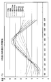
- FIG. It is a figure which shows the annual fluctuation
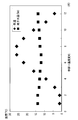
- FIG. It is a figure which shows the annual fluctuation
- FIG. It is a figure which shows the structure of the electrical storage apparatus and heat exchange apparatus which concern on Embodiment 4.
- FIG. It is a figure which shows the structure of the electrical storage apparatus and heat exchange apparatus which concern on Embodiment 5.
- FIG. 5 shows the structure of the electrical storage apparatus and heat exchange apparatus which concern on Embodiment 5.
- FIG. 1 is a diagram illustrating a configuration of the power control apparatus 100 according to the first embodiment.
- FIG. 2 is a diagram showing the configuration of power storage device 3 and heat exchange device 11 in the first embodiment.
- the power control device 100 includes a power storage device 3, a control unit 2, and a heat exchange device 11.
- the power storage device 3 includes a plurality of lithium ion battery cells 31.
- the control unit 2 includes a DC / AC conversion device 21, a switch 22, a processing circuit 23, and a memory 24.
- the control unit 2 controls the connection between the power storage device 3 and the external load 6 and the connection between the power storage device 3 and the external AC system by the switch 22.
- the external load 6 is a load in a facility such as a television, a radio, an air conditioner, a fan, or a refrigerator.
- the external power supply source is, for example, the solar module 1.
- the DC / AC conversion device 21 provided in the control unit 2 converts AC power supplied from the AC system 4 into DC and charges the power storage device 3. Further, the DC / AC conversion device 21 converts the DC power output from the power storage device 3 into, for example, 100 volt AC and supplies it to the external load 6.
- the power control apparatus 100 may receive power supply only from the AC system 4 without being connected to the solar module 1. Further, instead of the solar module 1, for example, a wind power generator may be connected.
- the lithium ion battery cell 31 may be removable from the power storage device 3.
- the removed lithium ion battery cell 31 is mounted on, for example, an electric vehicle.
- the power control apparatus 100 is provided with a first temperature sensor 10 that constantly measures the temperature of the power storage device 3.
- a temperature range in which the power control apparatus 100 operates safely (hereinafter referred to as a safe operating temperature range) is set in advance and stored in the memory 24.
- the processing circuit 23 acquires the temperature of the power storage device 3 from the first temperature sensor 10, and when the temperature is outside the safe operating temperature range, for example, controls the DC / AC conversion device and the power storage device 3 to perform the charging / discharging operation. Stop.
- the processing circuit 23 controls the DC / AC conversion device 21, and converts the electric power generated by the solar module 1 into an appropriate voltage to charge the power storage device 3 during the daytime.
- the processing circuit 23 controls the DC / AC conversion device 21 to charge the power storage device 3 with power supplied from the AC system 4 at night when the power rate is low.
- the processing circuit 23 controls the switch 22 to disconnect from the AC system 4 from the power control device 100 and supply the electric power stored in the power storage device 3 to the external load 6.
- the power control apparatus 100 may include an operation terminal 9 so that the user can easily instruct such control.
- the processing circuit 23 may be dedicated hardware.
- the processing circuit 23 may be a CPU (Central Processing Unit, central processing unit, processing unit, arithmetic unit, microprocessor, microcomputer, processor, DSP) that executes a program stored in the memory 24.
- CPU Central Processing Unit
- processing unit processing unit
- arithmetic unit microprocessor
- microcomputer processor
- DSP DSP
- the processing circuit 23 is dedicated hardware, the processing circuit 23 is, for example, a single circuit, a composite circuit, a programmed processor, a parallel programmed processor, an ASIC, an FPGA, or a combination thereof. .
- the processing circuit 23 When the processing circuit 23 is a CPU, the processing circuit 23 reads out and executes the program stored in the memory 24, thereby realizing the above-described operation.
- the memory 24 is, for example, a nonvolatile or volatile semiconductor memory such as a RAM, a ROM, a flash memory, an EPROM, an EEPROM, a magnetic disk, a flexible disk, an optical disk, a compact disk, a mini disk, a DVD, or the like. Applicable.
- processing circuit 23 may be realized by dedicated hardware, and part of it may be realized by software or firmware. As described above, the processing circuit 23 can realize each operation described above by hardware, software, firmware, or a combination thereof.
- the heat exchange device 40 contacts the power storage device 3 and geothermal heat that can be used in the installation environment of the power storage device 3.
- the heat exchange device 40 includes a plurality of heat pipes 41. As shown in FIG. 2, the outline of each lithium ion battery cell 31 provided in the power storage device 3 comes into contact with one end of the heat pipe 41 so that the heat of the lithium ion battery cell 31 is transmitted to the heat pipe 41. The other end of the heat pipe 41 is buried in the ground.
- FIG. 3 is a diagram showing the annual fluctuation of the outside air temperature and the underground temperature. As shown in FIG. 3, the temperature in the ground is not easily affected by the outside air temperature, and the temperature change becomes smaller as the depth increases. As shown in FIG. 3, when a few meters are dropped from the ground, the underground temperature is kept constant at about 15 to 20 ° C. throughout the year.
- the temperature of the power storage device 3 can be brought close to a stable temperature in the ground by connecting the ground and the power storage device 3 installed on the ground by the heat pipe 41.
- the temperature is low, such as in winter, or in a cold region
- the power storage device 3 can be warmed by heat in the ground through the heat pipe 41.
- the temperature of the power storage device 3 rises due to heat generated during charging / discharging of the power storage device 3, heat generated by power loss during circuit operation of the DC / AC converter 21 and the processing circuit 23, and the like.
- the control unit 2 performs control to suppress the output of the power storage device 3. Further, when the temperature continues to rise, the control unit 2 stops the operation of the power control device 2 for ensuring safety.
- the heat exchange device 40 (that is, the heat pipe 41) does not require electric power to operate, and thus it is possible to suppress a decrease in power conversion efficiency in the power control device 100.
- the power control apparatus 100 includes a power storage device 3 including a lithium ion battery (lithium ion battery cell 31), a power storage device 3, and an external load 6 or an external power supply source (solar module 1, AC A control unit 2 that controls electrical connection with the system 4), a power storage device 3, and a heat exchange device 40 that comes into contact with geothermal, hydrothermal, or air heat that can be used in the installation environment of the power storage device 3. .
- a power storage device 3 including a lithium ion battery (lithium ion battery cell 31), a power storage device 3, and an external load 6 or an external power supply source (solar module 1, AC A control unit 2 that controls electrical connection with the system 4), a power storage device 3, and a heat exchange device 40 that comes into contact with geothermal, hydrothermal, or air heat that can be used in the installation environment of the power storage device 3. .
- the power control device 100 brings the power storage device 3 and the geothermal heat available in the installation environment of the power storage device 3 through the heat exchange device 40. If the geothermal temperature is stable throughout the year, it is possible to maintain the temperature of the power storage device 3 with a simple configuration using geothermal heat. Thus, by maintaining the temperature of the power storage device 3 using geothermal heat that can be used in the installation environment, there is no need to provide air conditioning equipment in the power control device 100, and no power is supplied to the air conditioning equipment. It is possible to suppress a decrease in power conversion efficiency of the power control apparatus 100. Moreover, even if it is a case where the air-conditioning installation is provided in the electric power control apparatus 100, it becomes possible to suppress the electric power supplied to an air-conditioning installation.
- the power control apparatus 100 according to the first embodiment does not require excavation work for burying the main body of the power storage device 3 in the ground, the installation cost can be suppressed. Moreover, since the power control apparatus 100 in this Embodiment 1 can be installed outdoors, the indoor space of the facility 15 where the power control apparatus 100 is provided is not sacrificed.
- the heat exchange device 40 includes a heat pipe 41 whose one end is in contact with the power storage device 3 and whose other end is buried in the ground.
- the power storage device 3 When the temperature is low such as in winter, the power storage device 3 is warmed by the heat of the ground through the heat pipe 41 by connecting the power storage device 3 with the ground where the temperature is stable throughout the year. On the other hand, when the temperature is high such as in summer, the heat of the power storage device 3 is released into the ground through the heat pipe 41. Thus, by using the heat pipe 41, the temperature of the power storage device 3 can be stabilized with a simple configuration. In addition, since the temperature of the power storage device 3 can be stabilized without requiring a power source, it is possible to suppress a decrease in power conversion efficiency of the power control device 100.
- the power control apparatus 200 is provided in some facility 15.
- a facility 15 includes equipment that uses groundwater (or tap water, river water)
- the power control device 200 according to the second embodiment maintains the temperature of the power storage device 3 using this equipment. .
- FIG. 4 is a diagram showing the power storage device 3 and the heat exchange device 40 according to the second embodiment.
- the heat exchange device 40 comes into contact with the power storage device 3 and the water heat that can be used in the installation environment of the power storage device 3.
- the heat exchange device 40 includes a heat exchange tube 42.
- the heat exchange tube 42 is disposed in the power storage device 3 in contact with the power storage device 3.
- a water supply source 12 that supplies water is connected to one end of the heat exchange pipe 32.
- the water supply source 12 is, for example, a water pipe that supplies groundwater.
- the other end of the heat exchange pipe 42 is connected to, for example, a facility 15 that uses the power control apparatus 200. That is, the groundwater that has passed through the heat exchange pipe 42 is used in the facility 15.
- the heat exchange pipe 32 is branched into a plurality of parts and is in contact with each lithium ion battery cell 31.
- the heat exchange efficiency can be further improved by branching the heat exchange tube 32 into a capillary tube.
- FIG. 5 is a diagram showing the annual fluctuation of the outside air temperature and the groundwater temperature. As shown in FIG. 5, the temperature of groundwater is not easily affected by changes in air temperature, and is stable at about 15 ° C. throughout the year.
- the temperature of the power storage device 3 It is possible to bring the temperature of the power storage device 3 close to the stable temperature of the groundwater by passing the constant temperature groundwater through the heat exchanging pipe 42.
- the temperature is low, such as in winter, or in a cold region, the power storage device 3 can be warmed by the heat of the groundwater through the heat exchange pipe 42.
- the temperature of the electrical storage device 3 exceeds the safe operating temperature range.
- the temperature of the power storage device 3 rises when the temperature is high such as in summer, the heat of the power storage device 3 is released to the groundwater through the heat exchange pipe 42. Thereby, the power storage device 3 can be cooled.
- the power control apparatus 200 according to the second embodiment is provided in the facility 15.
- the groundwater can be passed through the heat exchange pipe 42 by using the equipment using the groundwater provided in the facility 15. Therefore, it is not necessary to newly provide the power control apparatus 200 with facilities for pumping up groundwater. Further, the groundwater flowing through the power storage device 3 is used in the facility 15.
- the other end of the heat exchanging pipe 42 is connected to the facility 15 using the power control apparatus 200, but may be connected to a path returning to the water supply source 12. Moreover, you may drain to the surrounding environment, without returning to the water supply source 12.
- the water supply source 12 is groundwater, but tap water may be used. It may also be river water.
- the power control apparatus 200 requires a facility for pumping up groundwater and a power source for operating the facility. In this case, it is possible to always circulate the water through the heat exchanging pipe 42 by returning the water whose temperature has changed after use to the original position (underground or river).
- the power control apparatus 200 includes a power storage device 3 including a lithium ion battery (lithium ion battery cell 31), a power storage device 3, and an external load 6 or an external power supply source (solar module 1, AC A control unit 2 that controls electrical connection with the system 4), a power storage device 3, and a heat exchange device 40 that comes into contact with geothermal, hydrothermal, or air heat that can be used in the installation environment of the power storage device 3. .
- a power storage device 3 including a lithium ion battery (lithium ion battery cell 31), a power storage device 3, and an external load 6 or an external power supply source (solar module 1, AC A control unit 2 that controls electrical connection with the system 4), a power storage device 3, and a heat exchange device 40 that comes into contact with geothermal, hydrothermal, or air heat that can be used in the installation environment of the power storage device 3. .
- the power control device 200 brings the power storage device 3 into contact with the water heat that can be used in the installation environment of the power storage device 3 via the heat exchange device 40. If the hydrothermal temperature is stable throughout the year, it is possible to maintain the temperature of the power storage device 3 with a simple configuration using hydrothermal heat. In this way, by maintaining the temperature of the power storage device 3 using the water heat that can be used in the installation environment, it is not necessary to provide the cooling / heating equipment in the power control device 200, and the power supplied to the cooling / heating equipment becomes unnecessary. It is possible to suppress a decrease in power conversion efficiency of the power control apparatus 200. Moreover, even if it is a case where the air-conditioning equipment is provided in the electric power control apparatus 200, it becomes possible to suppress the electric power supplied to the air-conditioning equipment.
- the power control apparatus 200 according to the second embodiment does not require excavation work for burying the main body of the power storage device 3 in the ground, the installation cost can be suppressed. Moreover, since the power control apparatus 200 according to the second embodiment can be installed outdoors, the indoor space of the facility 15 in which the power control apparatus 100 is provided is not sacrificed.
- the heat exchanging device 40 includes a heat exchanging tube 42 that is in contact with the electric storage device 3 and disposed in the electric storage device 3.
- a water supply source 12 for supplying water is connected to one end.
- the water supplied from the water supply source 12 whose temperature is stable throughout the year is brought into contact with the power storage device 3 through the heat exchanging pipe 42.
- the temperature of the power storage device 3 is warmed by the water of the water supply source 12.
- the temperature is high such as in summer, the heat of the power storage device 3 is released to the water of the water supply source 12.
- the heat exchanging pipe 42 the temperature of the power storage device 3 can be stabilized with a simple configuration.
- the facility 15 is equipped with facilities that use the water of the water supply source 12, the temperature of the power storage device 3 can be stabilized without the need for a power source, and therefore the power conversion efficiency of the power control device 200 can be improved. It is also possible to suppress the decrease.
- the other end of the heat exchange pipe 42 is connected to the facility 15 that uses water, or is connected to a path that returns water to the water supply source 12.
- the water supply source 12 is groundwater. Since the temperature of groundwater is stable throughout the year, it is suitable as the water supply source 12 connected to the heat exchange pipe 42. In particular, when the facility 15 in which the power control device 200 is installed includes equipment that uses groundwater, the temperature of the power storage device 3 can be stabilized without requiring a power source. It is also possible to suppress a decrease in power conversion efficiency.
- the water supply source 12 may be a water pipe. Since the temperature of tap water is more stable throughout the year than the outside temperature, it is suitable as the water supply source 12 connected to the heat exchange pipe 42.
- the facility 15 in which the power control device 200 is installed includes a facility that uses tap water, the temperature of the power storage device 3 can be stabilized without requiring a power source. It is also possible to suppress a decrease in power conversion efficiency.
- the water supply source 12 may be a river. River water has a temperature that is more stable throughout the year than the outside temperature, and is therefore suitable as the water supply source 12 connected to the heat exchange pipe 42.
- the power control device can stabilize the temperature of the power storage device 3 without requiring a power source. It is also possible to suppress a decrease in power conversion efficiency of 200.
- FIG. 6 shows power storage device 3 and heat exchange device 40 in the third embodiment.
- the power control device 300 is different from the power control device 200 (FIG. 4) in the second embodiment in the bypass pipe 43, the second temperature sensor 11, the switching valve 14, and the switching valve control unit 16. Is further provided.
- the second temperature sensor 11 measures the temperature of water (for example, groundwater) supplied from the water supply source 12.
- the detour pipe 43 has one end connected to the water supply source 12 and the other end connected to the facility 15 that uses water. Further, the bypass pipe 43 is arranged away from the power storage device 3 and the power control device 300.
- the switching valve 14 switches the path through which water from the water supply source 12 flows to one of the heat exchanging pipe 42 and the detour pipe 43.
- the switching valve control unit 16 acquires the measured temperature from the first sensor temperature 10 and the second temperature sensor 11.
- the switching valve control unit 16 controls switching of the switching valve 14 based on a comparison between the temperature of the power storage device 3 and the water temperature of the water supply source 12.
- the switching valve control unit 16 is realized by, for example, the processing circuit 23 of FIG. Note that a processing circuit may be provided separately from the processing circuit 23 to realize the function of the switching valve control unit 16.
- the switching valve control unit 16 switches the switching valve 14 to the bypass pipe 43 side.
- the switching valve control unit 16 switches the switching valve 14 to the bypass pipe 43 side.
- the control operation of the switching valve control unit 16 described above is an example, and the switching valve 14 may be controlled by another control method.
- the power control device 300 includes a first temperature sensor 10 that measures the temperature of the power storage device 3, a second temperature sensor 11 that measures the temperature of water supplied from the water supply source 12, and one end thereof. Heat exchange is performed between the bypass pipe 43 that is connected to the water supply source 12, the other end is connected to the facility 15 that uses water, and is disposed away from the power storage device 3, and the water flow from the water supply source 12.
- a switching valve 14 that switches to one of the working pipe 42 or the bypass pipe 43, a switching valve control unit 16 that controls switching of the switching valve 14 based on the measured temperatures of the first temperature sensor 10 and the second temperature sensor 11, Is further provided.
- the switching valve control unit 16 switches the switching valve 14. And the water path is switched to the detour pipe 43. Therefore, even when the temperature of the water supply source 12 changes, the temperature of the power storage device 3 can be maintained within the safe operating temperature range.
- the power control apparatus 400 is attached to some facility 15.
- a facility 15 includes the ventilation facility 13
- the power control device 400 according to the fourth embodiment uses the ventilation facility 13 to maintain the temperature of the power storage device 3.
- FIG. 7 shows power storage device 3 and heat exchange device 40 in the fourth embodiment.
- the heat exchange device 40 comes into contact with the power storage device 3 and air heat that can be used in the installation environment of the power storage device 3.
- the heat exchange device 40 includes an air intake 44.
- the air intake 44 is disposed, for example, in the housing of the power storage device 3 so as to take airflow from the outside into the power storage device 3.
- the airflow taken in from the air intake 44 flows through the power storage device 3.
- the airflow from the outside is the airflow discharged from the ventilation equipment 13 of the facility 15.
- the ventilation equipment 13 provided in the facility 15 is provided with a ventilation equipment for removing humidity, for example, under a building floor. Moreover, the ventilation equipment 13 for discharging
- the indoor air of the facility 15 is discharged to the outside by the ventilation equipment 13 provided in the facility 15.
- the discharge side of the ventilation facility 13 is connected to the air intake port 44 provided in the power storage device 3.
- the temperature in the power storage device 3 can be kept constant by using heat absorption in the winter and heat dissipation in the summer. Although the temperature of the air exhausted from the ventilation facility 13 is changed by this series of operations, the efficiency of moisture removal and odor removal that is the original purpose of the ventilation facility 13 changes due to this. Absent.
- the air intake 44 is provided in the housing of the power storage device 3. However, when the power storage device 3 is disposed inside the housing of the power control device 400, the housing of the power control device 400 is used. An air intake 44 is provided in the body.
- the power control device 400 includes a power storage device 3 including a lithium ion battery (lithium ion battery cell 31), a power storage device 3, and an external load 6 or an external power supply source (solar module 1, AC A control unit 2 that controls electrical connection with the system 4), a power storage device 3, and a heat exchange device 40 that comes into contact with geothermal, hydrothermal, or air heat that can be used in the installation environment of the power storage device 3. .
- a power storage device 3 including a lithium ion battery (lithium ion battery cell 31), a power storage device 3, and an external load 6 or an external power supply source (solar module 1, AC A control unit 2 that controls electrical connection with the system 4), a power storage device 3, and a heat exchange device 40 that comes into contact with geothermal, hydrothermal, or air heat that can be used in the installation environment of the power storage device 3. .
- the power control device 400 brings the power storage device 3 into contact with the heat generated in the installation environment of the power storage device 3 via the heat exchange device 40. If the temperature of the air heat is stable throughout the year, it is possible to maintain the temperature of the power storage device 3 with a simple configuration using the air heat. Thus, by maintaining the temperature of the power storage device 3 using the air heat that can be used in the installation environment, it is not necessary to provide the air-conditioning equipment in the power control device 400, and the power to be supplied to the air-conditioning equipment becomes unnecessary. It is possible to suppress a decrease in power conversion efficiency of the power control apparatus 400. Moreover, even if it is a case where the air-conditioning equipment is provided in the electric power control apparatus 400, it becomes possible to suppress the electric power supplied to the air-conditioning equipment.
- the power control apparatus 400 according to the fourth embodiment does not require excavation work for burying the main body of the power storage device 3 in the ground, the installation cost can be suppressed. Moreover, since the power control apparatus 400 in this Embodiment 4 can be installed outdoors, the indoor space of the facility 15 where the power control apparatus 100 is provided is not sacrificed.
- heat exchange device 40 includes air intake port 44 that receives an airflow from the outside, and the airflow that is taken in from air intake port 44 flows through power storage device 3.
- the airflow discharged from the facility 15 whose temperature is stable throughout the year is taken into the power storage device 3 from the air intake port 44.
- the temperature of the power storage device 3 is warmed by the heat of the air flow taken in.
- the temperature is high, such as in summer, the power storage device 3 is cooled by the airflow that is introduced.
- the temperature of the power storage device 3 can be stabilized with a simple configuration.
- the temperature of the power storage device 3 can be stabilized without consuming new energy, it is possible to suppress a decrease in power conversion efficiency of the power control device 400.
- FIG. 8 is a diagram showing power storage device 3 and heat exchange device 40 in the fifth embodiment. As shown in FIG. 8, power control device 500 further includes cutoff device 17, second temperature sensor 11, and cutoff device control unit 18 with respect to power control device 400 (FIG. 7) in the fourth embodiment.
- the second temperature sensor 11 measures the temperature of the airflow discharged from the ventilation equipment 13 of the facility 15.
- the shut-off device 17 is in a state where an inflow of an external airflow into the air intake 44 is blocked (a state indicated by a dotted line in FIG. 8) and a state in which an external airflow is taken into the air intake 44 ( The state is switched to one shown in FIG.
- the shutoff device valve control 18 acquires the measured temperature from the first temperature sensor 10 and the second temperature sensor 11.
- the shut-off device valve control unit 18 controls switching of the shut-off device 17 based on a comparison between the temperature of the power storage device 3 and the temperature of the airflow discharged from the facility 15.
- the shut-off device control unit 18 is realized by, for example, the processing circuit 23 in FIG. Note that a processing circuit may be provided separately from the processing circuit 23 to realize the function of the shutoff device control unit 18.
- the shut-off device controller 18 switches the shut-off device 17 to a state in which the inflow of the external airflow into the air intake 44 is shut off.
- the shut-off device control unit 18 switches the shut-off device 17 to a state in which the inflow of an external air flow into the air intake 44 is shut off.
- shut-off device controller 18 The control operation of the shut-off device controller 18 described above is an example, and the shut-off device 17 may be controlled by another control method.
- the power control device 500 includes a first temperature sensor 10 that measures the temperature of the power storage device 3, a second temperature sensor 11 that measures the temperature of the external airflow, and an air intake port 44 for the external airflow. And a shut-off device controller 18 for controlling the shut-off device 17 based on the measured temperatures of the first temperature sensor 10 and the second temperature sensor 11.
- the shutoff device control unit 18 performs the shutoff device. 17 is switched so that the air current does not enter the power storage device 3. Thereby, even if the temperature of the airflow discharged from the facility 15 changes, the temperature of the power storage device 3 can be maintained within the safe operating temperature range.
Landscapes
- Engineering & Computer Science (AREA)
- Manufacturing & Machinery (AREA)
- Chemical & Material Sciences (AREA)
- Chemical Kinetics & Catalysis (AREA)
- Electrochemistry (AREA)
- General Chemical & Material Sciences (AREA)
- Automation & Control Theory (AREA)
- Supply And Distribution Of Alternating Current (AREA)
Abstract
L'objectif de la présente invention est de pourvoir à un dispositif de régulation de puissance dans lequel une variation de la température d'un dispositif de stockage d'électricité est supprimée au moyen d'une configuration simple, ledit dispositif de stockage d'électricité étant disposé dans le dispositif de régulation de puissance. Selon un mode de réalisation (1) de la présente invention, un dispositif de régulation de puissance (100) est équipé : d'un dispositif de stockage d'électricité (3) qui est pourvu d'une batterie lithium-ion (élément de batterie lithium-ion (31)) ; d'une unité de commande (2) qui commande la connexion électrique entre le dispositif de stockage d'électricité (3) et une charge externe (6) ou une source d'alimentation électrique externe ; et d'un dispositif d'échange de chaleur (40) qui est en contact avec le dispositif de stockage d'électricité (3), et de la chaleur géothermique, de la chaleur hydrothermique ou de la chaleur gazeuse qui peut être utilisée dans l'environnement d'installation du dispositif de stockage d'électricité (3).
Priority Applications (1)
| Application Number | Priority Date | Filing Date | Title |
|---|---|---|---|
| PCT/JP2015/073849 WO2017033285A1 (fr) | 2015-08-25 | 2015-08-25 | Dispositif de régulation de puissance |
Applications Claiming Priority (1)
| Application Number | Priority Date | Filing Date | Title |
|---|---|---|---|
| PCT/JP2015/073849 WO2017033285A1 (fr) | 2015-08-25 | 2015-08-25 | Dispositif de régulation de puissance |
Publications (1)
| Publication Number | Publication Date |
|---|---|
| WO2017033285A1 true WO2017033285A1 (fr) | 2017-03-02 |
Family
ID=58100736
Family Applications (1)
| Application Number | Title | Priority Date | Filing Date |
|---|---|---|---|
| PCT/JP2015/073849 Ceased WO2017033285A1 (fr) | 2015-08-25 | 2015-08-25 | Dispositif de régulation de puissance |
Country Status (1)
| Country | Link |
|---|---|
| WO (1) | WO2017033285A1 (fr) |
Cited By (2)
| Publication number | Priority date | Publication date | Assignee | Title |
|---|---|---|---|---|
| JP2020089020A (ja) * | 2018-11-21 | 2020-06-04 | 株式会社デンソー | 電池温度調節装置 |
| CN116093503A (zh) * | 2023-03-01 | 2023-05-09 | 长城汽车股份有限公司 | 加热控制方法及装置、车辆、可读存储介质 |
Citations (5)
| Publication number | Priority date | Publication date | Assignee | Title |
|---|---|---|---|---|
| JPH11350411A (ja) * | 1998-06-09 | 1999-12-21 | Fujikura Ltd | 地熱および補助熱源を利用したヒートパイプ式道路融雪装置 |
| JP2006054150A (ja) * | 2004-08-16 | 2006-02-23 | Sanyo Electric Co Ltd | 車両用の電源装置 |
| JP2010115043A (ja) * | 2008-11-07 | 2010-05-20 | Toyota Motor Corp | 充電装置、充電装置を備えた建物、及び温水生成装置 |
| JP2013218984A (ja) * | 2012-04-12 | 2013-10-24 | Kayaba Ind Co Ltd | 温度制御システム及び温度制御システムを備えるハイブリッド建設機械の駆動システム |
| JP2013251102A (ja) * | 2012-05-31 | 2013-12-12 | Nissan Motor Co Ltd | バッテリ制御装置 |
-
2015
- 2015-08-25 WO PCT/JP2015/073849 patent/WO2017033285A1/fr not_active Ceased
Patent Citations (5)
| Publication number | Priority date | Publication date | Assignee | Title |
|---|---|---|---|---|
| JPH11350411A (ja) * | 1998-06-09 | 1999-12-21 | Fujikura Ltd | 地熱および補助熱源を利用したヒートパイプ式道路融雪装置 |
| JP2006054150A (ja) * | 2004-08-16 | 2006-02-23 | Sanyo Electric Co Ltd | 車両用の電源装置 |
| JP2010115043A (ja) * | 2008-11-07 | 2010-05-20 | Toyota Motor Corp | 充電装置、充電装置を備えた建物、及び温水生成装置 |
| JP2013218984A (ja) * | 2012-04-12 | 2013-10-24 | Kayaba Ind Co Ltd | 温度制御システム及び温度制御システムを備えるハイブリッド建設機械の駆動システム |
| JP2013251102A (ja) * | 2012-05-31 | 2013-12-12 | Nissan Motor Co Ltd | バッテリ制御装置 |
Cited By (3)
| Publication number | Priority date | Publication date | Assignee | Title |
|---|---|---|---|---|
| JP2020089020A (ja) * | 2018-11-21 | 2020-06-04 | 株式会社デンソー | 電池温度調節装置 |
| JP7180312B2 (ja) | 2018-11-21 | 2022-11-30 | 株式会社デンソー | 電池温度調節装置 |
| CN116093503A (zh) * | 2023-03-01 | 2023-05-09 | 长城汽车股份有限公司 | 加热控制方法及装置、车辆、可读存储介质 |
Similar Documents
| Publication | Publication Date | Title |
|---|---|---|
| ES2890329T3 (es) | Instalación doméstica de energía y método de operación para operar una instalación doméstica de energía | |
| KR101466766B1 (ko) | 성능이 개선되고 수명이 연장된 인버터를 구비한 태양광 발전 시스템 | |
| KR101836360B1 (ko) | 지중열 및 태양열을 이용한 하이브리드 열교환 시스템 및 그 제어방법 | |
| US20140123644A1 (en) | Heat-electricity combined production system that utilizes solar energy and geothermal heat | |
| CN102460890A (zh) | 电力设施互连系统 | |
| JP4036851B2 (ja) | ソーラー発電システム | |
| JP2011217590A (ja) | 空調システム | |
| JP5441391B2 (ja) | 充電装置、充電装置を備えた建物、及び温水生成装置 | |
| US10674642B2 (en) | Electrical equipment housing | |
| WO2017033285A1 (fr) | Dispositif de régulation de puissance | |
| CN104053958A (zh) | 热电联产机组及其运行方法 | |
| JP2011200097A (ja) | 空調システム | |
| KR101726338B1 (ko) | 건물 일체형 태양광 발전시스템의 냉각시스템 | |
| US20150050574A1 (en) | Device and method for controlling cogeneration system | |
| JP6137951B2 (ja) | 燃料電池システム及びその停止方法 | |
| JP4969535B2 (ja) | 浴室暖房乾燥装置 | |
| JP2009266556A (ja) | 蓄電装置及び熱利用システム | |
| KR101523514B1 (ko) | 고성능 방열판 시스템을 적용한 저소음, 저진동 및 장수명 특성을 갖는 태양광 발전 시스템 | |
| JP6932706B2 (ja) | ソーラー一体型チラーの方法およびシステム | |
| RU2645203C1 (ru) | Система автоматического управления микроклиматом в помещениях для размещения животных | |
| CN121079559A (zh) | 热泵系统 | |
| JP2005241079A (ja) | 太陽光発電装置 | |
| JP2010140753A (ja) | 建物用蓄電システム | |
| RU2013108493A (ru) | Система автономного электро- и теплоснабжения жилых и производственных помещений | |
| HK40118227A (en) | Heat pump system |
Legal Events
| Date | Code | Title | Description |
|---|---|---|---|
| 121 | Ep: the epo has been informed by wipo that ep was designated in this application |
Ref document number: 15902254 Country of ref document: EP Kind code of ref document: A1 |
|
| NENP | Non-entry into the national phase |
Ref country code: DE |
|
| NENP | Non-entry into the national phase |
Ref country code: JP |
|
| 122 | Ep: pct application non-entry in european phase |
Ref document number: 15902254 Country of ref document: EP Kind code of ref document: A1 |