WO2017033458A1 - 加熱調理器 - Google Patents
加熱調理器 Download PDFInfo
- Publication number
- WO2017033458A1 WO2017033458A1 PCT/JP2016/003818 JP2016003818W WO2017033458A1 WO 2017033458 A1 WO2017033458 A1 WO 2017033458A1 JP 2016003818 W JP2016003818 W JP 2016003818W WO 2017033458 A1 WO2017033458 A1 WO 2017033458A1
- Authority
- WO
- WIPO (PCT)
- Prior art keywords
- convection
- circulation fan
- microwave
- wall
- heating
- Prior art date
- Legal status (The legal status is an assumption and is not a legal conclusion. Google has not performed a legal analysis and makes no representation as to the accuracy of the status listed.)
- Ceased
Links
Images






Classifications
-
- F—MECHANICAL ENGINEERING; LIGHTING; HEATING; WEAPONS; BLASTING
- F24—HEATING; RANGES; VENTILATING
- F24C—DOMESTIC STOVES OR RANGES ; DETAILS OF DOMESTIC STOVES OR RANGES, OF GENERAL APPLICATION
- F24C7/00—Stoves or ranges heated by electric energy
- F24C7/02—Stoves or ranges heated by electric energy using microwaves
-
- H—ELECTRICITY
- H05—ELECTRIC TECHNIQUES NOT OTHERWISE PROVIDED FOR
- H05B—ELECTRIC HEATING; ELECTRIC LIGHT SOURCES NOT OTHERWISE PROVIDED FOR; CIRCUIT ARRANGEMENTS FOR ELECTRIC LIGHT SOURCES, IN GENERAL
- H05B6/00—Heating by electric, magnetic or electromagnetic fields
- H05B6/64—Heating using microwaves
- H05B6/647—Aspects related to microwave heating combined with other heating techniques
- H05B6/6473—Aspects related to microwave heating combined with other heating techniques combined with convection heating
-
- H—ELECTRICITY
- H05—ELECTRIC TECHNIQUES NOT OTHERWISE PROVIDED FOR
- H05B—ELECTRIC HEATING; ELECTRIC LIGHT SOURCES NOT OTHERWISE PROVIDED FOR; CIRCUIT ARRANGEMENTS FOR ELECTRIC LIGHT SOURCES, IN GENERAL
- H05B6/00—Heating by electric, magnetic or electromagnetic fields
- H05B6/64—Heating using microwaves
- H05B6/76—Prevention of microwave leakage, e.g. door sealings
Definitions
- the present disclosure relates to a heating cooker that performs microwave heating by microwave irradiation on an object to be heated, and in particular, a commercial heating cooker used as a heating cooker in a commercial facility such as a convenience store or a fast food store. About.
- the heater is installed in a commercial cooking device used in convenience stores and fast food stores.
- a configuration having a grill mode for cooking the object to be heated by radiant heating and a convection mode for cooking the object to be heated by convection of the air heated by the heater using a fan is used.
- a commercial heating cooker used in a store or the like it is necessary to reliably execute each heating step of various types of heating cooking at a predetermined accurate temperature and time. Furthermore, it is important to shorten cooking time in a commercial heating cooker so that it can quickly respond to customer orders. For this reason, in a commercial heating cooker, a high-frequency output for microwave heating and a heater that is a heating source in the grill mode or the convection mode have a large power consumption.
- a commercial cooking device various devices with high output are used to shorten cooking time.
- a commercial heating cooker that can simultaneously perform at least one of the grill mode and the convection mode together with the microwave heating mode by microwave irradiation, use a high-power device efficiently to shorten the cooking time. It is necessary to plan.
- the present disclosure efficiently performs cooking in the microwave heating mode by suppressing microwave leakage in a mechanism that executes the convection mode.
- An object of the present invention is to provide a cooking device that can shorten cooking time in the mode.
- a heating cooker includes a heating chamber for storing and heating an object to be heated, and a microwave is formed in the heating chamber in order to heat the object to be heated in the microwave heating mode.
- a microwave heating mechanism that radiates waves, a convection heating mechanism that heats an object to be heated in the convection mode, and a microwave leakage suppression mechanism that suppresses leakage of the microwave are provided.
- the convection heating mechanism takes in air from the heating chamber, sends out air to the heating chamber, a convection heater for heating air taken in from the heating chamber by the circulation fan, and takes in from the heating chamber by the circulation fan
- the hot air guide for guiding the generated air to the convection heater and guiding the direction of the hot air sent to the heating chamber by the circulation fan to a desired position in the heating chamber, and the fan that drives the circulation fan shaft that rotates the circulation fan
- a drive unit The convection heater and the circulation fan are arranged inside the convection formation space communicating with the heating chamber, and the fan driving unit is arranged outside the convection formation space.
- the microwave leakage suppression mechanism forms a gap between the circulation fan shaft that penetrates the first wall that forms the convection formation space and the first wall, and sets a distance between opposed surfaces of the gap to be equal to or less than a predetermined distance. It has a coaxial seal mechanism and suppresses microwave leakage from the convection formation space.
- the microwave radiated into the heating chamber in the cooking in the microwave heating mode is greatly suppressed from leaking in the mechanism for performing the cooking in the convection mode.
- the cooking-by-heating machine which performs cooking with high efficiency of microwave heating mode can be provided.
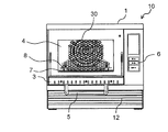
- Drawing 1 is a perspective view showing the state where the door of the cooking-by-heating machine concerning an embodiment of this indication was closed.
- Drawing 2 is a perspective view showing the state where the door of the cooking-by-heating machine concerning an embodiment of this indication opened.
- Drawing 3 is a front view showing the state where the door of the cooking-by-heating machine concerning an embodiment of this indication opened.
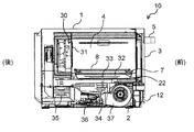
- FIG. 4 is a vertical cross-sectional view of the heating cooker according to the embodiment of the present disclosure.
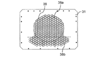
- FIG. 5 is a front view showing the back wall of the heating chamber in the heating cooker according to the embodiment of the present disclosure.
- FIG. 6 is a front view showing the convection device behind the heating chamber in the heating cooker according to the embodiment of the present disclosure.
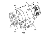
- FIG. 7 is an exploded perspective view of the convection device in the cooking device according to the embodiment of the present disclosure.
- FIG. 8 is a perspective view showing the arrangement of the convection device in a state where the casing is removed in the cooking device according to the embodiment of the present disclosure.
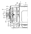
- FIG. 9 is a cross-sectional view of the convection device in the cooking device according to the embodiment of the present disclosure cut along the rotation center axis of the circulation fan.
- FIG. 10 is an enlarged cross-sectional view illustrating a configuration of the convection device in the heating cooker according to the embodiment of the present disclosure.
- FIG. 11 is a cross-sectional view showing the vicinity of the front end side of the circulation fan shaft to which the circulation fan is fixed in the cooking device according to the embodiment of the present disclosure.
- FIG. 12 is a graph based on the results of experiments performed using the heating cooker according to the embodiment of the present disclosure.
- FIG. 13 is a cross-sectional view illustrating a metal mesh seal mechanism and the like of a microwave leakage suppression mechanism in the cooking device according to the embodiment of the present disclosure.
- a heating cooker includes a heating chamber for storing and heating an object to be heated, and forming and heating a microwave to heat the object to be heated in the microwave heating mode.
- a microwave heating mechanism that radiates microwaves to the chamber, a convection heating mechanism that heats an object to be heated in the convection mode, and a microwave leakage suppression mechanism that suppresses microwave leakage are provided.
- the convection heating mechanism takes in air from the heating chamber, sends out air to the heating chamber, a convection heater for heating air taken in from the heating chamber by the circulation fan, and takes in from the heating chamber by the circulation fan
- the hot air guide for guiding the generated air to the convection heater and guiding the direction of the hot air sent to the heating chamber by the circulation fan to a desired position in the heating chamber, and the fan that drives the circulation fan shaft that rotates the circulation fan
- a drive unit The convection heater and the circulation fan are arranged inside the convection formation space communicating with the heating chamber, and the fan driving unit is arranged outside the convection formation space.
- the microwave leakage suppression mechanism forms a gap between the circulation fan shaft that penetrates the first wall that forms the convection formation space and the first wall, and sets a distance between opposed surfaces of the gap to be equal to or less than a predetermined distance. It has a coaxial seal mechanism and suppresses microwave leakage from the convection formation space.
- the cooking device configured as described above suppresses microwave leakage in the convection heating mechanism that executes the convection mode in the cooking device having the microwave heating mode and the convection mode. Can do. Thereby, the cooking in the microwave heating mode can be performed with high efficiency, and the cooking time in the microwave heating mode can be shortened.
- the heating cooker according to the second aspect of the present disclosure may be configured such that, in the first aspect, a distance between facing surfaces of the gap between the circulation fan shaft and the first wall may be 3.0 mm or less.
- the microwave leakage suppression mechanism includes a fan support portion that fixes the circulation fan at a predetermined position with respect to the circulation fan shaft, and the first wall. And an annular first bushing fixed so as to cover the inner surface of the through hole penetrating the circulation fan shaft. Further, in a state where the fan support portion penetrates the first bushing, the distance between the facing surfaces of the fan support portion and the first bushing may be 3.0 mm or less.
- the fan support section according to the third aspect has a flat surface portion having a flat surface for fixing the circulation fan at a predetermined position, and the circulation fan orthogonal to the plane of the flat surface portion. And a cylindrical portion that covers the outer peripheral surface of the shaft. And even if the distance between the opposing surfaces of the inner peripheral surface of the first bushing and the outer peripheral surface of the cylindrical portion is 3.0 mm or less, and the distance between the opposing surfaces of the first bushing and the flat portion is 3.0 mm or less. Good.
- the heating cooker according to the fifth aspect of the present disclosure may include a second wall that covers the first wall forming the convection forming space according to the fourth aspect with the space interposed therebetween. Further, the circulation fan shaft passes through the first wall and the second wall, and the fan drive unit is coupled to the circulation fan shaft that penetrates the second wall, except for the surface facing the heating chamber in the convection formation space. You may comprise a double wall structure.
- a heating cooker includes a circulation fan shaft as a microwave leakage suppression mechanism according to the fifth aspect by a leakage suppression wall provided so as to couple the first wall and the second wall.
- a leakage suppression space that surrounds may be formed.
- the heating cooker according to the seventh aspect of the present disclosure is arranged in an annular shape around the circulation fan shaft penetrating the second wall as the microwave leakage suppression mechanism in the fifth aspect.
- a metal mesh seal portion may be provided on the side where the fan drive portion is disposed.
- the metal mesh seal part in the seventh aspect is fixed to the second wall by being pressed against the second wall by the seal part press-contact plate penetrating the circulation fan shaft.
- a microwave sealing space may be formed inside the metal mesh seal portion by a pressure contact plate.
- the cooking device of the ninth aspect according to the present disclosure is fixed to the seal portion pressure welding plate as the microwave leakage suppression mechanism in the eighth aspect, and is disposed with a predetermined interval with respect to the outer peripheral surface of the circulation fan shaft.
- a second bushing having a coaxial seal function may be provided.
- the distance between the opposed surfaces of the inner peripheral surface of the second bushing and the outer peripheral surface of the circulation fan shaft may be 1.0 mm or less.
- a heating cooker capable of executing a microwave heating mode, a grill mode, and a convection mode
- a cooking device that is a microwave oven for business use in stores such as convenience stores and fast food stores will be described with reference to the accompanying drawings.
- the cooking device of the present disclosure is not limited to the configuration of the commercial microwave oven described in the following embodiment, but the technical idea equivalent to the technical idea described in the following embodiment.
- the structure of the heating cooker based on is included.
- FIG. 1 is a perspective view showing an appearance of a heating cooker 10 according to an embodiment of the present disclosure, and shows a state where a door formed on the front surface of the heating cooker 10 is closed.
- FIG. 2 shows a state in which the door in the heating cooker 10 shown in FIG. 1 is opened and the heating chamber formed inside the heating cooker 10 is opened.
- the heating cooker 10 is a microwave oven for business use particularly in stores such as convenience stores and fast food restaurants, and is configured to be capable of switching outputs in multiple stages up to a maximum output of about 2000 W.
- the heating cooker 10 includes a main body 1 constituting an outer box of the heating chamber 4, and a machine room 2 provided below the main body 1 so as to support the main body 1. And a door 3 attached to the front side of the main body 1.
- a removable front grille panel 12 is provided on the front side of the machine room 2.
- a heating chamber 4 is formed inside the main body 1.
- the heating chamber 4 is a substantially rectangular parallelepiped space having an opening on the front side (door side) in order to accommodate an object to be heated therein.
- the side where the opening of the heating chamber 4 is formed is defined as the front side of the heating cooker 10
- the back side of the heating chamber 4 is defined as the rear side of the heating cooker 10.
- the right side of the cooking device 10 when the cooking device 10 is viewed from the front is simply referred to as the right side
- the left side of the cooking device 10 when the cooking device 10 is viewed from the front is simply referred to as the left side.
- the door 3 is attached to the front side of the main body 1 so as to be openable and closable by vertically opening so as to close the opening in front of the heating chamber 4.
- a user can hold the handle 5 provided on the door 3 so that the door 3 can be opened and closed.
- the inside of the heating chamber 4 is a sealed space in which a heat treatment using microwaves or the like is performed on the object to be heated.
- the door 3 shown in FIG. 2 is opened, the user puts an object to be heated into and out of the heating chamber 4.
- an operation unit 6 is provided on the front right side of the main body 1, and the operation unit 6 is used to set and operate the cooking conditions for the heating cooker 10. Buttons and display screens are provided.
- a tray 7 made of ceramics (specifically, cordierite (made of ceramics composed of 2MgO ⁇ 2Al 2 O 3 ⁇ 5SiO 2)) and a stainless steel wire rack 8 are placed inside the heating chamber 4. It is arranged so that it can be accommodated.
- the wire rack 8 is a placing portion made of a net-like member for placing the object to be heated, and can efficiently circulate hot air also on the lower surface of the object to be heated.
- the tray 7 is provided below the wire rack 8 and is disposed so as to receive a fat or the like dripping from an object to be heated on the wire rack 8.
- the machine room 2 below the heating room 4 is provided with a magnetron 35 (see FIG. 4 described later) that is a microwave generation unit.
- the microwave from the magnetron 35 is configured to be radiated from the microwave radiation hole formed in the waveguide and the opening formed on the bottom surface side of the heating chamber 4 through the waveguide.
- emitted in the inside of the heating chamber 4 from the microwave radiation hole of a waveguide and the opening formed in the bottom face of the heating chamber 4 is stirred with a stirrer (stirrer).
- the object to be heated accommodated in the heating chamber 4 is heated by the microwave by the heating cooker configured as described above.
- the grill heater comprised with the sheathed heater is provided in the ceiling side of the heating chamber 4, and the inside of the heating chamber 4 is heated with the radiant heat from a grill heater. The object is directly heated and the grill mode is executed.
- a convection device 30 (see a cross-sectional view in FIG. 4), which will be described later, for supplying hot air to the inside of the heating chamber 4 is provided behind the back wall of the heating chamber 4.
- the convection device 30 has a function of sucking air inside the heating chamber 4 from the center, heating the sucked air, and blowing it out as hot air into the heating chamber 4. In this way, hot air is supplied into the heating chamber 4 by the convection device 30, and a circulating flow by the hot air is generated inside the heating chamber 4.
- the convection device 30 sucks air from the central region of the heating chamber 4 and heats the sucked air into hot air from the front side of the bottom surface and the front side of the ceiling to the inside of the heating chamber 4 to generate hot air. Circulating.
- FIG. 3 is a front view showing a state in which the door 3 is opened in the heating cooker 10 of the present embodiment, and shows that the convection device 30 is provided behind the back wall 31 of the heating chamber 4. ing.
- the heating by the microwave from the magnetron 35 that is the microwave generating unit and the grill heater provided on the upper side (ceiling wall side) of the heating chamber 4 are used.
- the heating by the radiation and the heating by the circulating flow of hot air using the convection device 30 can be performed separately or simultaneously.
- the heating cooker 10 has a configuration in which a heater that is a large heat source is not disposed below an object to be heated accommodated in the heating chamber 4. For this reason, it becomes a highly safe cooking device in which liquids such as oils dripping from the object to be heated do not come into contact with the heater and smoke or ignition does not occur.
- a magnetron 35 as a microwave generation unit for generating a microwave
- an inverter device 36 for driving the magnetron 35
- a cooling fan 37 for cooling the magnetron 35, the inverter device 36, and the like. (See FIG. 4).
- two magnetrons 35 are used, and the total output is 1200 W to 1300 W.
- the microwaves output from the two magnetrons are transmitted through the two waveguides, and the microwave radiation openings formed in the respective waveguides and the openings formed in the bottom surface of the heating chamber 4 are transmitted. Through the heating chamber 4.
- the microwave is stirred by the stirrer 32 and radiated into the heating chamber 4.
- the inverter device 36 drives the magnetron 35, and two inverter devices 36 are provided in the machine room 2 to drive the two magnetrons 35.
- a plurality of cooling fans 37 for cooling the magnetron 35 and the inverter device 36 are arranged in the machine room 2. In the present embodiment, four cooling fans 37 are provided, and two are a set. Then, each cooling fan 37 sucks outside air from the front grill panel 12 provided on the front surface of the machine room 2, and sends the outside air sucked by each pair of cooling fans 37 to the rear, whereby the inside of the machine room 2.
- the two sets of inverter devices 36 and magnetrons 35 arranged in a column as the microwave heating mechanism provided in FIG.
- the machine room 2 is provided with a power circuit board, and further provided with a cooling fan for cooling the power circuit board.
- a cooling fan for cooling the power circuit board.
- cooling fans 37 arranged in parallel to cool the heat generating portions such as the inverter device 36 and the magnetron 35, and one cooling fan that cools the power supply circuit board are multi-blade fans or the like. It is comprised and it installs so that each rotating shaft may be located in a line.
- the cooling fan is configured to take in air from the axial direction of the rotary shaft and send out air toward the rear of the machine room 2 in the outer peripheral direction.
- the air that flows backward in the machine room 2 passes through the exhaust duct disposed on the back surface of the main body 1, passes between the ceiling wall of the heating chamber 4 and the top wall of the main body 1, and is discharged from the front side of the main body 1.
- the air from the cooling fan flows to prevent the upper surface wall of the back wall of the main body 1 from becoming hot.
- FIG. 4 is a longitudinal sectional view of the cooking device 10 in the front-rear direction, and the right side of FIG. 4 is the front side (front side).
- the tray 7 is placed on the tray support 22.
- the tray support 22 is provided on the bottom surface of the heating chamber 4 and supports the tray 7.
- the tray support 22 is made of a ceramic plate that can transmit microwaves.
- a stirrer (stirrer) 32 that stirs the microwave radiated into the heating chamber 4 is provided between the tray support 22 and the bottom surface of the heating chamber 4.
- the stirrer 32 is a rotary blade that rotates around the stirrer shaft 33 in order to stir the microwave.
- the motor 34 is provided inside the machine room 2 and rotationally drives the stirrer 32.
- a microwave heating mechanism such as a magnetron 35 that is a microwave generation unit that generates a microwave, an inverter device 36 that drives the magnetron 35, and a cooling fan 37 that cools the magnetron 35 and the inverter device 36.
- two sets of magnetron 35 and inverter device 36 are provided as described above, and these magnetron 35 and inverter device 36 are cooled by four cooling fans 37. Is done.
- the magnetron 35 and the inverter device 36 are cooled by a plurality of cooling fans 37 (four cooling fans 37 in the present embodiment) provided inside the machine room 2, and inside the machine room 2 by one cooling fan 37.
- the disposed power circuit board and the like are cooled.
- the cooling fan 37 When the cooling fan 37 is activated, outside air is sucked from the front grill panel 12 mounted on the front surface of the machine room 2, passes through the outside air inlet formed on the front surface of the machine room 2, and is sucked into the machine room 2. .
- the air sucked into the machine room 2 cools members inside the machine room 2, then passes through an exhaust duct disposed on the back surface of the main body 1, and passes between the ceiling wall of the heating chamber 4 and the top wall of the main body 1. And is discharged from the front side of the main body 1.
- a plurality of openings 38 are formed in the back wall 31 (see FIG. 5 described later) constituting the rear wall of the heating chamber 4.
- the openings 38 in the back wall 31 in the present embodiment are a plurality of punching holes formed in the back wall 31 made of a plate material by punching.
- Behind the rear wall 31 is provided a convection device 30 that takes in the air in the heating chamber 4, generates hot air by heating, and sends the hot air into the heating chamber 4.
- the arrangement space of the convection device 30 is separated from the internal space of the heating chamber 4 by the back wall 31 and communicates with the internal space of the heating chamber 4 through a plurality of openings 38 formed in the back wall 31.
- the convection device 30 is a convection heating mechanism.
- FIG. 5 is a front view of the back wall 31.
- the back wall 31 is formed of a substantially rectangular metal plate.
- the plurality of openings 38 formed in the back wall 31 include a first hole 38a that is a punching hole formed in a group in a substantially circular shape in the center portion of the back wall 31 (the center portion of the heating chamber 4), and a first hole 38a.
- the second hole 38b which is a punching hole formed in a group in a horizontally long shape below the hole 38a.
- the group of second holes 38 b are formed so as to be more widely distributed in the left-right direction below the heating chamber 4 than the group of first holes 38 a.
- the group of first holes 38a formed in the back wall 31 functions as an air intake port to the convection device 30, and the group of second holes formed below the group of first holes 38a.
- the hole 38b functions as a hot air outlet from the convection device 30.
- the diameter of the punching hole formed in the heating chamber is 4 to 5 mm.
- the diameters of the first hole 38a and the second hole 38b of the opening 38 functioning as an air intake port and a hot air outlet port for the convection device 30 are both 10 mm, and a general convection oven Has a diameter about twice that of the punching hole.
- the convection device 30 is provided with a hot air generating mechanism 39 composed of a plurality of members for generating hot air.
- the hot air generation mechanism 39 has a function of taking in the air in the heating chamber 4, heating the taken-in air to generate hot air, and sending it into the heating chamber 4. In this way, the hot air generating mechanism 39 supplies hot air into the heating chamber 4, whereby a hot air circulation flow is generated in the heating chamber 4.
- the heating and the heating by the circulating flow of hot air using the hot air generating mechanism 39 of the convection device 30 can be performed separately or simultaneously.
- a heater since a heater is not disposed below the object to be heated, liquid such as oil dripping from the object to be heated does not come into contact with the heater that is a heat source, and smoke or ignition Will never happen.
- FIG. 6 is a front view showing the convection device 30 provided behind the back wall 31 of the heating chamber 4.
- FIG. 7 is an exploded perspective view showing the hot air generating mechanism 39 in the convection device 30.
- FIG. 8 is a perspective view showing a partially broken arrangement of the convection device 30 provided behind the heating chamber 4 by removing the casing that is the cover of the main body 1 in the cooking device of the present embodiment. is there.
- FIG. 8 in order to show the configuration of the convection device 30, a part of the convection device 30 is shown in cross section, and the configuration other than the convection device 30 is omitted.
- the hot air generating mechanism 39 includes a convection heater 40 provided immediately after the rear wall 31 of the heating chamber 4, a circulation fan 41, a fan driving unit 42 that rotationally drives the circulation fan 41, and hot air in the hot air generation mechanism 39.
- First and second hot air guides 43 and 44 for guiding are provided.
- the convection heater 40 is configured using a sheathed heater, and heats the air inside the convection device 30.
- the convection heater 40 is formed in a spiral shape in the central portion of the convection device 30 (corresponding to the central portion of the heating chamber) in order to increase the contact area with air.
- the circulation fan 41 is a centrifugal fan that takes in air at its central portion and sends out the taken-in air in the centrifugal direction.
- the circulation fan 41 takes the air inside the heating chamber 4 into the convection device 30 through the opening 38 of the back wall 31, and the inside of the convection device 30. In this configuration, air is sent out to the heating chamber 4.
- the circulation fan 41 is disposed behind the convection heater 40 and is driven by a fan driving unit 42 provided behind the circulation fan 41.
- the circulation fan 41 rotates in the direction of the arrow R (see FIG. 7) will be described, but the same function is provided even in the reverse direction.
- the first hot air guide 43 is a guide member that guides the air taken into the convection device 30 by the circulation fan 41 so as to pass through the region of the convection heater 40, and surrounds the convection heater 40. Has been placed.
- the first hot air guide 43 is formed in a substantially cylindrical shape.
- the first hot air guide 43 is formed with a notch 43a for extending the lead-out portion of the convection heater 40 on the inside outward.
- the second hot air guide 44 is a member for guiding the hot air sent out in the centrifugal direction by the circulation fan 41 in a desired direction, and is arranged so as to surround the outside of the circulation fan 41 and the first hot air guide 43. Yes. In the present embodiment, the second hot air guide 44 is in partial contact with the first hot air guide 43 outside the first hot air guide 43.
- the fan driving unit 42 drives the circulation fan 41 so that the air inside the heating chamber 4 is opened in the back wall 31. It is sucked into the convection device 30 through 38 (first hole 38a). The sucked air is guided to the area of the convection heater 40 by the first hot air guide 43 and heated by the convection heater 40.
- the circulation fan 41 takes in the air (hot air) heated by the convection heater 40 and sends it out in a spiral toward the outer periphery of the circulation fan 41.
- the air sent out to the outer periphery by the circulation fan 41 is guided by the second hot air guide 44 and into a lower space formed on the lower side between the first hot air guide 43 and the second hot air guide 44. Guided.
- the hot air guided by the first hot air guide 43 and the second hot air guide 44 in the convection device 30 passes through the opening 38 (second hole 38 b) of the back wall 31 and is below the inside of the heating chamber 4. Sent out.
- an air intake path from the first hole 38 a of the opening 38 in the back wall 31 to the circulation fan 41 is formed in the space surrounded by the first hot air guide 43. Further, in the space between the first hot air guide 43 and the second hot air guide 44, a hot air sending path from the circulation fan 41 to the second hole 38b of the opening 38 in the back wall 31 is formed. .
- the 1st hot air guide 43 functions as a guide plate which isolate
- the convection device 30 As shown in FIG. 8, the convection device 30 according to the present embodiment configured as described above is attached to a back wall 31 that forms a wall surface behind the heating chamber 4.
- the convection heater 40 and the circulation fan 41 in the convection device 30 are covered with a convection device case 45 fixed to the back wall 31.
- a plurality of openings 38 (a first hole 38a and a second hole 38b) having a diameter of 10 mm are formed in the back wall 31 of the heating chamber 4, and in the convection mode The pressure loss of air when passing through the opening 38 of the back wall 31 is greatly reduced.
- the diameter of the punching hole formed in the heating chamber in the conventional convection oven is 4 to 5 mm, and the opening 38 formed in the back wall 31 in the present embodiment is about twice the punching hole in the conventional convection oven. It has a diameter. For this reason, the heating cooker of this Embodiment has the pressure loss significantly reduced in hot air circulation compared with the conventional convection oven.
- each of the plurality of openings 38 (the first hole 38a and the second hole 38b) formed in the back wall 31 of the heating chamber 4 is formed large. Therefore, when the microwave heating mode is executed, about 2.5% to 3% (about 30 W) of the microwave radiated into the heating chamber 4 passes through the opening 38 of the back wall 31.
- the microwave that has passed through the opening 38 of the back wall 31 leaks to the outside of the convection device case 45, it causes a significant reduction in the heating efficiency in the heat treatment in the microwave heating mode.
- the microwaves leaking to the outside of the cooking device via the convection device 30 can be greatly reduced so that the heat treatment in the microwave heating mode can be performed efficiently.
- a plurality of microwave leakage suppression mechanisms described in (1) are provided.
- FIG. 9 is a cross-sectional view of the convection device 30 disposed behind the heating chamber 4 taken along the rotation center axis of the circulation fan 41, and shows a state in which the outer casing covering the heating chamber 4 is removed. Yes.
- FIG. 10 is an enlarged cross-sectional view illustrating a configuration of a convection heating mechanism such as the circulation fan 41, the fan drive unit 42, and the circulation fan shaft 46 in the convection device 30.
- a convection heater 40 is disposed behind the back wall 31 of the heating chamber 4. Behind the spiral convection heater 40, a circulation fan 41 having a rotation center at a substantially center of the convection heater 40 is provided.
- a circulation fan shaft 46 that is the rotation center of the circulation fan 41 is rotationally driven by a fan drive unit 42 that is an electric motor.
- the circulation fan 41 is fixed to the front end side of the circulation fan shaft 46, and the fan drive unit 42 that is an electric motor is provided on the rear end side of the circulation fan shaft 46.
- the fan drive unit 42 is rotationally driven.
- the circulation fan shaft 46 is rotatably held by two bearings 55 on the rear side where the fan driving unit 42 is provided.
- the circulation fan shaft 46 is held by the bearing 55 in a cantilever state. This is because the front side (front end side) of the circulation fan shaft 46 becomes high temperature due to heat from the heating chamber 4 and microwaves, so that no bearing is provided.
- a convection space forming wall 50 which is a wall surface provided immediately after the circulation fan 41, is provided behind the back wall 31.
- the convection forming space A is formed by the convection space forming wall 50 and the back wall 31. Is formed.
- a part of the convection space forming wall 50 is the second hot air guide 44 described above.
- the convection heater 40 and the circulation fan 41 are provided in the convection formation space A. Therefore, in the space of the convection formation space A, the air taken in from the inside of the heating chamber 4 is heated, and the heated air (hot air) becomes inside the heating chamber 4 (in the present embodiment, the heating chamber 4 (Downward).
- the convection formation space A formed by the convection space formation wall 50 (including the second hot air guide 44) that is the first wall is covered by the convection device case 45 that is the second wall, and the fan drive unit.
- the fan drive unit case 54 covering the 42 is fixed to the convection device case 45 which is the second wall. Therefore, the surface other than the surface (back wall 31) facing the heating chamber 4 in the convection forming space A in the present embodiment has a double wall structure.
- a plurality of microwave leakage suppression mechanisms in the convection device 30 configured as described above are provided around the circulation fan shaft 46 that rotates the circulation fan 41.
- a plurality of microwave leakage suppression mechanisms will be described.
- the first microwave leakage suppression mechanism is a coaxial seal mechanism formed by a gap formed between the convection space forming wall 50 that is the first wall disposed behind the circulation fan 41 and the circulation fan shaft 46.
- the second microwave leakage suppression mechanism is provided at a stage subsequent to the first microwave leakage suppression mechanism, and includes a leakage suppression space B formed behind the convection space forming wall 50 (see FIG. 10). ).
- the third microwave leakage suppression mechanism is provided in the subsequent stage of the second microwave leakage suppression mechanism, and is configured by a microwave sealing space C.
- the fourth microwave leakage suppression mechanism is a coaxial seal mechanism that is provided at a subsequent stage of the third microwave leakage suppression mechanism and is a gap around the circulation fan shaft 46.
- a multi-stage microwave leakage suppression mechanism is provided in the convection device 30, and leakage of microwaves from the convection device 30 to the outside of the cooking device is prevented. It is greatly suppressed.
- a microwave output of 30 W enters the convection device 30 through the plurality of openings 38 in the back wall 31 of the heating chamber 4.
- the microwave output of about 97 dB was reduced by the multi-stage microwave leakage suppression mechanism provided in the convection device 30, and only a very small microwave output of about 0.4 mW was leaked.
- FIG. 11 is a cross-sectional view showing the vicinity of the front end side (near the front end side) of the circulation fan shaft 46 to which the circulation fan 41 is fixed.
- a fan fastener 47 for fixing the circulation fan 41 to the circulation fan shaft 46 is screwed into the tip of the circulation fan shaft 46.
- the central portion of the circulation fan 41 is sandwiched between the fan support portion 48 and the pressing plate 57 fixed in the vicinity of the tip of the circulation fan shaft 46. It is a configuration.
- the fan support 48 is fixed by being pierced through the circulation fan shaft 46 and has a T-shaped cross section.
- the fan support part 48 is integrally formed with a flat part 48 a having a plane orthogonal to the rotation center axis of the circulation fan shaft 46 and protruding rearward from the center of the flat part 48 a, and is in close contact with the outer periphery of the circulation fan shaft 46.
- a cylindrical portion 48b formed as described above. Therefore, in the circulation fan 41 into which the tip portion of the circulation fan shaft 46 is inserted, the fan fastener 47 is screwed into the tip portion of the circulation fan shaft 46, so that the holding plate 57 and the flat portion 48 a of the fan support portion 48 are used. It is clamped and securely fixed to the circulation fan shaft 46.
- a first bushing 49 is provided in the through hole of the convection space forming wall 50, which is the first wall through which the circulation fan shaft 46 passes.
- the first bushing 49 is mounted so as to cover the inner peripheral surface of the through hole of the convection space forming wall 50 through which the circulation fan shaft 46 passes, and is formed in an annular shape having a through hole in the center.
- the first bushing 49 has a facing surface that faces the outer surface of the fan support portion 48 with a predetermined distance.
- the first bushing 49 has a front end portion (an end portion in the direction in which the circulation fan 41 is provided) formed on a flat surface, and the flat surface is referred to as an opposing Y plane 49y in the following description.
- the first bushing 49 has a through hole that penetrates through the tubular portion 48 b of the fan support portion 48 that is in close contact with the outer peripheral surface of the circulation fan shaft 46.
- the inner peripheral surface of the through hole of the first bushing 49 is an opposing X plane 49x that faces the outer peripheral surface of the cylindrical portion 48b of the fan support portion 48.
- the rear end surface of the flat portion 48a facing the opposing Y plane 49y of the first bushing 49 becomes the opposing Y plane 48y.
- the outer peripheral surface of the cylindrical part 48b in the fan support part 48 becomes the opposing X plane 48x.
- the fan support portion 48 and the first bushing 49 are disposed such that the opposing Y planes 48y and 49y and the opposing X planes 48x and 49x are opposed to each other with a predetermined gap. Therefore, the fan support portion 48 and the first bushing 49 are disposed with the rotation center axis of the circulation fan shaft 46 as the same axis, and have a configuration of a coaxial seal mechanism having a predetermined distance between the opposed surfaces.
- the distance between the opposing surfaces refers to the shortest distance between the opposing surfaces. In the present embodiment shown in FIG.
- the shortest distance in the left-right direction in the gap extending vertically between the opposing Y planes 48y and 49y is the distance between the opposing surfaces, and the right and left between the opposing X planes 48x and 49x.
- the shortest distance in the up-down direction in the gap extending in the direction is the distance between the opposing surfaces.
- the clearance between the opposing Y planes 48y and 49y (between the opposing surfaces) is set to 1.5 mm, and the clearance between the opposing X planes 48x and 49x (between the opposing surfaces). Is also set to 1.5 mm.
- the gap between the opposing Y planes 48y and 49y (between the opposing surfaces) and the gap between the opposing X planes 48x and 49x (between the opposing surfaces) are set to 1.5 mm as described above. Although described with an example, the shorter the distance, the better.
- the circulation fan shaft 46 is held in a cantilevered manner by the bearing 55 provided behind the circulation fan shaft 46. It is preferable that there is a gap. Actually, the gap can be manufactured within a range of 0.8 mm to 1.2 mm.
- the reference performance is 3.0 mm or less at worst. It turned out that it can secure.
- the following experimental results were obtained as a result of a plurality of samples.
- FIG. 12 is a graph showing experimental results regarding the gap (distance between opposing surfaces) and microwave leakage power as described above, where the vertical axis indicates microwave leakage power [W] and the horizontal axis indicates the opposing Y plane. A gap (distance between opposing surfaces) [mm] between 48y and 49y is shown.
- FIG. 12 the experimental result by the various samples from which the distance between opposing surfaces differs is shown.
- the microwave leakage power rapidly increases when the gap exceeds 3.0 mm. Therefore, it is preferable that the distance between the opposing surfaces for reliably suppressing microwave leakage is 3.0 mm or less. More preferably, the distance between the opposing surfaces is 2.0 mm or less. More preferably, when the distance between the opposing surfaces is 1.0 mm or less, the leakage of the microwave is less than 0.5 W, and particularly excellent effects are exhibited.
- the second microwave leakage suppression mechanism is provided in the subsequent stage of the first microwave leakage suppression mechanism, and the microwave power leaked from the first microwave leakage suppression mechanism is behind the convection space forming wall 50. Leakage of the microwave is suppressed by the leakage suppression space B (see FIG. 9 and FIG. 10) formed in the.
- the leakage suppression space B is formed around the circulation fan shaft 46 by a leakage suppression wall 51 disposed so as to connect the convection space forming wall 50 that is the first wall and the convection device case 45 that is the second wall. It is a space formed so as to surround.
- the leakage suppression space B In the leakage suppression space B, the outer circumferential direction is closed by the leakage suppression wall 51, the convection space forming wall 50 is the front wall surface, and the convection device case 45 is the rear wall surface.
- the microwave leaked from the first microwave leakage suppression mechanism interferes, and the microwave power is reduced.
- the third microwave leakage suppression mechanism is formed behind the leakage suppression space B constituting the second microwave leakage suppression mechanism, and is configured by a metal mesh seal mechanism.
- FIG. 13 is a cross-sectional view showing the metal mesh seal mechanism of the third microwave leakage suppression mechanism formed behind the leakage suppression space B.
- a metal mesh seal 52 is provided in close contact with the convection device case 45 serving as the rear wall of the leakage suppression space B.
- the metal mesh seal portion 52 is formed by assembling stainless mesh wires, and is arranged in an annular shape around the circulation fan shaft 46.
- sticker part 52 is simplified and shown.
- the metal mesh seal portion 52 Since the metal mesh seal portion 52 is formed by gathering mesh wires, it is an elastic body having elasticity as a whole. Therefore, the metal mesh seal portion 52 is firmly fixed to the convection device case 45 by being pressed by the fixing means, for example, the seal portion pressure contact plate 53 fixed by screwing.
- the seal of the metal mesh seal portion 52 is not limited to the metal mesh, and equivalent performance can be ensured even if a metal contact seal is adopted.
- the microwave is sealed in the metal mesh seal portion 52.
- the metal mesh seal portion 52 is pressed and fixed to the convection device case 45 as the second wall by a seal portion press-contact plate 53 that penetrates the circulation fan shaft 46, and the metal mesh seal portion is pressed by the seal portion press-contact plate 53.
- a substantial microwave sealing space C is formed inside 52. That is, the microwave sealing space C is formed by the convection device case 45, the metal mesh seal portion 52, and the seal portion pressure contact plate 53.
- the fourth microwave leakage suppression mechanism is provided at the subsequent stage of the metal mesh seal mechanism that is the third microwave leakage suppression mechanism.
- the fourth microwave leakage suppression mechanism is a coaxial seal mechanism configured by a second bushing 56 disposed at a predetermined interval with respect to the outer peripheral surface of the circulation fan shaft 46.
- the seal portion press contact plate 53 for fixing the metal mesh seal portion 52 to the back surface (rear surface) of the convection device case 45 is protruded forward around the circulation fan shaft 46. It has a chevron shaped protrusion 53a. Therefore, the protruding portion 53 a of the seal portion pressure contact plate 53 is disposed at the center portion of the metal mesh seal portion 52 that is annularly disposed around the circulation fan shaft 46.
- the fourth microwave leakage suppression mechanism is configured by a metal second bushing 56 provided so as to face the outer peripheral surface of the circulation fan shaft 46 that penetrates the protruding portion 53 a of the seal portion pressure contact plate 53.
- the second bushing 56 is made of aluminum metal, but may be a conductor metal.
- the gap between the outer peripheral surface of the circulation fan shaft 46 and the inner peripheral surface of the second bushing 56 (distance between opposing surfaces) is set to 0.5 mm.
- the distance between the opposing surfaces is preferably as short as possible.
- the distance between the outer peripheral surface of the circulation fan shaft 46 and the inner peripheral surface of the second bushing 56 is preferred.
- a distance of 0.5 mm between the opposing surfaces is a distance that greatly reduces microwave leakage.
- the distance between the opposing surfaces between the outer peripheral surface of the circulation fan shaft 46 and the inner peripheral surface of the second bushing 56 is set to 1.0 mm or less as described above in order to suppress microwave leakage. preferable.
- the axial length of the opposing surface in the coaxial seal mechanism constituted by the circulation fan shaft 46 and the second bushing 56 is 10 mm. The longer the better.
- the configuration may be such that hot air is sent above the heating chamber 4 (ceiling side).
- the cooking device thus configured can be configured such that hot air heated by at least one of the convection heater 40 of the convection device 30 and the grill heater on the ceiling side of the heating chamber 4 circulates in the convection mode. .
- the present disclosure is a configuration applicable to a heating cooker that heats and cooks an object to be heated, and is particularly suitable for business use having a microwave heating mode and a convection mode used in convenience stores, fast food stores, and the like. It is useful in a high-speed cooking device such as a microwave oven.
Landscapes
- Physics & Mathematics (AREA)
- Electromagnetism (AREA)
- Engineering & Computer Science (AREA)
- Chemical & Material Sciences (AREA)
- Combustion & Propulsion (AREA)
- Mechanical Engineering (AREA)
- General Engineering & Computer Science (AREA)
- Electric Ovens (AREA)
- Constitution Of High-Frequency Heating (AREA)
Abstract
Description
加熱調理器10の内部構造について、図4を用いて説明する。図4は、加熱調理器10の前後方向の縦断面図であり、図4の右側が前方側(正面)である。
次に、本実施の形態の加熱調理器10におけるコンベクション加熱機構である対流装置30の構成について説明する。
本実施の形態の加熱調理器10においては、加熱室4の背面壁31に直径が10mmの複数の開口38(第1の孔38aおよび第2の孔38b)が形成されており、コンベクションモードにおいて背面壁31の開口38を通過する際の空気の圧力損失を大幅に低減している。従来のコンベクションオーブンにおける加熱室に形成されたパンチング孔の直径は4~5mmであり、本実施の形態における背面壁31に形成された開口38は、従来のコンベクションオーブンにおけるパンチング孔の約2倍の直径となっている。このため、本実施の形態の加熱調理器は、従来のコンベクションオーブンに比べて熱風循環において圧力損失が大幅に低減されている。
先ず、第1のマイクロ波漏洩抑制機構(同軸シール機構)について図11を用いて説明する。図11は、循環ファン41が固定された循環ファン軸46の先端側近傍(前方端側近傍)を示した断面図である。
隙間(対向面間の距離)2.0mmの場合-マイクロ波漏れ電力0.94W
隙間(対向面間の距離)2.2mmの場合-マイクロ波漏れ電力1.20W
隙間(対向面間の距離)3.0mmの場合-マイクロ波漏れ電力2.49W
隙間(対向面間の距離)3.2mmの場合-マイクロ波漏れ電力7.85W
上記の実験および計算においては、1300Wのマイクロ波出力の加熱調理器を使用し、対流装置30の対流形成空間Aの内部に30Wのマイクロ波電力が漏洩していた。
第2のマイクロ波漏洩抑制機構は、前述の第1のマイクロ波漏洩抑制機構の後段に設けられており、第1のマイクロ波漏洩抑制機構から漏洩したマイクロ波電力を対流空間形成壁50の後方に形成された漏洩抑制空間B(図9および図10参照)によりマイクロ波の漏れを抑制する。漏洩抑制空間Bは、第1の壁である対流空間形成壁50と、第2の壁である対流装置ケース45とを結合するように配設された漏洩抑制壁51により循環ファン軸46の周りを取り囲むように形成された空間である。漏洩抑制空間Bは、その外周方向が漏洩抑制壁51により閉塞されており、対流空間形成壁50が前方壁面となり、対流装置ケース45が後方壁面となる。上記のように構成された第2のマイクロ波漏洩抑制機構においては、第1のマイクロ波漏洩抑制機構から漏洩したマイクロ波が干渉し、マイクロ波電力が低減される。
第3のマイクロ波漏洩抑制機構は、第2のマイクロ波漏洩抑制機構を構成する漏洩抑制空間Bの後方に形成されており、金属メッシュシール機構により構成されている。図13は、漏洩抑制空間Bの後方に形成された第3のマイクロ波漏洩抑制機構の金属メッシュシール機構を示す断面図である。
第4のマイクロ波漏洩抑制機構は、第3のマイクロ波漏洩抑制機構である金属メッシュシール機構の後段に設けられている。第4のマイクロ波漏洩抑制機構は、循環ファン軸46の外周面に対して所定間隔を有して配設された第2ブッシング56により構成された同軸シール機構である。
2 機械室
3 扉
4 加熱室
5 把手
6 操作部
7 トレイ
8 ワイヤラック
10 加熱調理器
12 フロントグリルパネル
30 対流装置
31 背面壁
35 マグネトロン
36 インバータ装置
37 冷却ファン
38 開口
39 熱風生成機構
40 対流ヒータ
41 循環ファン
42 ファン駆動部
43 第1の熱風ガイド
44 第2の熱風ガイド
45 対流装置ケース
46 循環ファン軸
47 ファン留め具
48 ファン支持部
49 第1ブッシング
50 対流空間形成壁
51 漏洩抑制壁
52 金属メッシュシール部
53 シール部圧接板
54 ファン駆動部ケース
55 軸受け
56 第2ブッシング
Claims (10)
- 被加熱物を収容して加熱するための加熱室と、
マイクロ波加熱モードにおいて前記被加熱物を加熱するために、マイクロ波を形成して前記加熱室に前記マイクロ波を放射するマイクロ波加熱機構と、
コンベクションモードにおいて前記被加熱物を加熱するコンベクション加熱機構と、
マイクロ波の漏洩を抑制するマイクロ波漏洩抑制機構と、を備えた加熱調理器において、
前記コンベクション加熱機構は、
前記加熱室から空気を取り込み、前記加熱室へ空気を送り出すための循環ファンと、
前記循環ファンにより前記加熱室から取り込まれた空気を加熱するための対流ヒータと、
前記循環ファンにより前記加熱室から取り込まれた空気を、前記対流ヒータに案内し、前記循環ファンにより前記加熱室に送り出される熱風の方向を前記加熱室における所望の位置に案内するための熱風ガイドと、
前記循環ファンを回転する循環ファン軸を駆動するファン駆動部と、を備え、
前記対流ヒータおよび前記循環ファンは前記加熱室と連通する対流形成空間の内部に配置され、前記対流形成空間の外部に前記ファン駆動部が配置され、
前記マイクロ波漏洩抑制機構は、前記対流形成空間を形成する第1の壁を貫通する前記循環ファン軸と前記第1の壁との間に隙間を形成し、当該隙間の対向面間を所定距離以下に設定する同軸シール機構を有し、前記対流形成空間からのマイクロ波の漏洩を抑制する加熱調理器。 - 前記循環ファン軸と前記第1の壁との間の隙間の対向面間が3.0mm以下である請求項1に記載の加熱調理器。
- 前記マイクロ波漏洩抑制機構は、前記循環ファン軸に対して前記循環ファンを所定位置に固定するファン支持部と、前記第1の壁において前記循環ファン軸に貫通される貫通孔の内面を覆うように固定された環状の第1ブッシングと、を有しており、
前記ファン支持部が前記第1ブッシングを貫通した状態において、前記ファン支持部と前記第1ブッシングとの対向面間が3.0mm以下である請求項2に記載の加熱調理器。 - 前記ファン支持部は、前記循環ファンを所定位置に固定するための平面を有する平面部と、前記平面部の平面に直交する前記循環ファン軸の外周面を覆う筒状部と、を有しており、
前記第1ブッシングの内周面と前記筒状部の外周面との対向面間が3.0mm以下であり、且つ前記第1ブッシングと前記平面部との対向面間が3.0mm以下である請求項3に記載の加熱調理器。 - 前記対流形成空間を形成する前記第1の壁を空間を挟んで覆う第2の壁を備え、
前記循環ファン軸が前記第1の壁と前記第2の壁を貫通し、前記ファン駆動部が前記第2の壁を貫通した前記循環ファン軸に結合されて、前記対流形成空間における前記加熱室に対向する面以外が二重壁構造で構成された請求項4に記載の加熱調理器。 - 前記マイクロ波漏洩抑制機構として、前記第1の壁と前記第2の壁とを結合するように設けた漏洩抑制壁により前記循環ファン軸を取り囲む漏洩抑制空間が形成された請求項5に記載の加熱調理器。
- 前記マイクロ波漏洩抑制機構として、前記第2の壁を貫通した前記循環ファン軸を中心として環状に配設され、前記第2の壁における前記ファン駆動部の配設側に金属メッシュシール部が設けられた請求項5に記載の加熱調理器。
- 前記金属メッシュシール部は、前記循環ファン軸に貫通されたシール部圧接板により前記第2の壁に押圧されて固定され、前記シール部圧接板により前記金属メッシュシール部の内側にマイクロ波封止空間が形成された請求項7に記載の加熱調理器。
- 前記マイクロ波漏洩抑制機構として、前記シール部圧接板に固定され、前記循環ファン軸の外周面に対して所定間隔を有して配置された同軸シール機能を有する第2ブッシングが設けられた請求項8に記載の加熱調理器。
- 前記第2ブッシングの内周面と前記循環ファン軸の外周面との対向面間が1.0mm以下である請求項9に記載の加熱調理器。
Priority Applications (5)
| Application Number | Priority Date | Filing Date | Title |
|---|---|---|---|
| US15/573,011 US10697643B2 (en) | 2015-08-26 | 2016-08-23 | Cooker |
| JP2017536617A JP6782400B2 (ja) | 2015-08-26 | 2016-08-23 | 加熱調理器 |
| CA2988528A CA2988528C (en) | 2015-08-26 | 2016-08-23 | Cooker |
| EP16838808.0A EP3343110B1 (en) | 2015-08-26 | 2016-08-23 | Cooker |
| CN201680026922.7A CN107532802B (zh) | 2015-08-26 | 2016-08-23 | 加热烹调器 |
Applications Claiming Priority (2)
| Application Number | Priority Date | Filing Date | Title |
|---|---|---|---|
| JP2015166744 | 2015-08-26 | ||
| JP2015-166744 | 2015-08-26 |
Publications (1)
| Publication Number | Publication Date |
|---|---|
| WO2017033458A1 true WO2017033458A1 (ja) | 2017-03-02 |
Family
ID=58101187
Family Applications (1)
| Application Number | Title | Priority Date | Filing Date |
|---|---|---|---|
| PCT/JP2016/003818 Ceased WO2017033458A1 (ja) | 2015-08-26 | 2016-08-23 | 加熱調理器 |
Country Status (6)
| Country | Link |
|---|---|
| US (1) | US10697643B2 (ja) |
| EP (1) | EP3343110B1 (ja) |
| JP (1) | JP6782400B2 (ja) |
| CN (1) | CN107532802B (ja) |
| CA (1) | CA2988528C (ja) |
| WO (1) | WO2017033458A1 (ja) |
Cited By (4)
| Publication number | Priority date | Publication date | Assignee | Title |
|---|---|---|---|---|
| CN107543215A (zh) * | 2017-08-31 | 2018-01-05 | 广东美的厨房电器制造有限公司 | 烹饪电器 |
| JP2022051855A (ja) * | 2018-11-15 | 2022-04-01 | 三菱電機株式会社 | ビルトイン式複合型加熱調理器及び厨房家具 |
| JP2022051856A (ja) * | 2018-11-15 | 2022-04-01 | 三菱電機株式会社 | ビルトイン式複合型加熱調理器及び厨房家具 |
| CN114532855A (zh) * | 2020-11-25 | 2022-05-27 | 宁波方太厨具有限公司 | 一种烹饪设备的导风散热结构及烹饪设备 |
Families Citing this family (3)
| Publication number | Priority date | Publication date | Assignee | Title |
|---|---|---|---|---|
| JP7149501B2 (ja) * | 2019-01-10 | 2022-10-07 | パナソニックIpマネジメント株式会社 | 加熱調理器 |
| US11849527B2 (en) * | 2021-02-15 | 2023-12-19 | Haier Us Appliance Solutions, Inc. | Oven appliance with improved convection cooking performance |
| JP7607199B2 (ja) * | 2021-10-04 | 2024-12-27 | パナソニックIpマネジメント株式会社 | 加熱調理器 |
Citations (7)
| Publication number | Priority date | Publication date | Assignee | Title |
|---|---|---|---|---|
| JPS54811Y2 (ja) * | 1974-11-08 | 1979-01-17 | ||
| JPS56117498U (ja) * | 1980-02-12 | 1981-09-08 | ||
| JPS5850164Y2 (ja) * | 1978-10-04 | 1983-11-15 | リンナイ株式会社 | 加熱調理装置 |
| JPH08247473A (ja) * | 1995-03-10 | 1996-09-27 | Toshiba Corp | 加熱調理器 |
| JPH103985A (ja) * | 1996-06-17 | 1998-01-06 | Matsushita Electric Ind Co Ltd | 高周波加熱装置 |
| JP2002093571A (ja) * | 2000-09-14 | 2002-03-29 | Tanico Corp | マイクロ波加熱装置の扉シールド構造 |
| WO2015118867A1 (ja) * | 2014-02-05 | 2015-08-13 | パナソニックIpマネジメント株式会社 | 加熱調理器 |
Family Cites Families (9)
| Publication number | Priority date | Publication date | Assignee | Title |
|---|---|---|---|---|
| JPS54811U (ja) | 1977-06-06 | 1979-01-06 | ||
| EP0006997B1 (de) * | 1978-07-12 | 1983-01-19 | Bosch-Siemens HausgerÀ¤te GmbH | Mikrowellenofen |
| JPS5850164U (ja) | 1981-09-30 | 1983-04-05 | ティー・シー・エム株式会社 | 産業車両用バルブ操作レバ−の係止装置 |
| JPS6035477A (ja) * | 1984-07-23 | 1985-02-23 | 住友電気工業株式会社 | 改良されたアルミニウムブスバー |
| DE3738267A1 (de) * | 1987-11-11 | 1989-05-24 | Miele & Cie | Mikrowellenofen |
| DE4105300C2 (de) * | 1991-02-20 | 1997-02-13 | Bosch Siemens Hausgeraete | Gebläse für einen Umluftherd |
| JP4483653B2 (ja) | 2005-03-29 | 2010-06-16 | パナソニック株式会社 | 加熱調理装置 |
| EP2869667B1 (en) * | 2013-10-31 | 2021-12-15 | Electrolux Appliances Aktiebolag | Microwave oven |
| CN204100320U (zh) * | 2014-08-22 | 2015-01-14 | 宁波方太厨具有限公司 | 一种微波炉的防微波泄漏结构 |
-
2016
- 2016-08-23 EP EP16838808.0A patent/EP3343110B1/en active Active
- 2016-08-23 CA CA2988528A patent/CA2988528C/en active Active
- 2016-08-23 CN CN201680026922.7A patent/CN107532802B/zh active Active
- 2016-08-23 WO PCT/JP2016/003818 patent/WO2017033458A1/ja not_active Ceased
- 2016-08-23 JP JP2017536617A patent/JP6782400B2/ja active Active
- 2016-08-23 US US15/573,011 patent/US10697643B2/en active Active
Patent Citations (7)
| Publication number | Priority date | Publication date | Assignee | Title |
|---|---|---|---|---|
| JPS54811Y2 (ja) * | 1974-11-08 | 1979-01-17 | ||
| JPS5850164Y2 (ja) * | 1978-10-04 | 1983-11-15 | リンナイ株式会社 | 加熱調理装置 |
| JPS56117498U (ja) * | 1980-02-12 | 1981-09-08 | ||
| JPH08247473A (ja) * | 1995-03-10 | 1996-09-27 | Toshiba Corp | 加熱調理器 |
| JPH103985A (ja) * | 1996-06-17 | 1998-01-06 | Matsushita Electric Ind Co Ltd | 高周波加熱装置 |
| JP2002093571A (ja) * | 2000-09-14 | 2002-03-29 | Tanico Corp | マイクロ波加熱装置の扉シールド構造 |
| WO2015118867A1 (ja) * | 2014-02-05 | 2015-08-13 | パナソニックIpマネジメント株式会社 | 加熱調理器 |
Non-Patent Citations (1)
| Title |
|---|
| See also references of EP3343110A4 * |
Cited By (7)
| Publication number | Priority date | Publication date | Assignee | Title |
|---|---|---|---|---|
| CN107543215A (zh) * | 2017-08-31 | 2018-01-05 | 广东美的厨房电器制造有限公司 | 烹饪电器 |
| CN107543215B (zh) * | 2017-08-31 | 2019-07-02 | 广东美的厨房电器制造有限公司 | 烹饪电器 |
| JP2022051855A (ja) * | 2018-11-15 | 2022-04-01 | 三菱電機株式会社 | ビルトイン式複合型加熱調理器及び厨房家具 |
| JP2022051856A (ja) * | 2018-11-15 | 2022-04-01 | 三菱電機株式会社 | ビルトイン式複合型加熱調理器及び厨房家具 |
| JP7292450B2 (ja) | 2018-11-15 | 2023-06-16 | 三菱電機株式会社 | ビルトイン式複合型加熱調理器及び厨房家具 |
| JP7292449B2 (ja) | 2018-11-15 | 2023-06-16 | 三菱電機株式会社 | ビルトイン式複合型加熱調理器及び厨房家具 |
| CN114532855A (zh) * | 2020-11-25 | 2022-05-27 | 宁波方太厨具有限公司 | 一种烹饪设备的导风散热结构及烹饪设备 |
Also Published As
| Publication number | Publication date |
|---|---|
| EP3343110B1 (en) | 2019-10-23 |
| US20180119961A1 (en) | 2018-05-03 |
| CN107532802A (zh) | 2018-01-02 |
| JPWO2017033458A1 (ja) | 2018-06-07 |
| US10697643B2 (en) | 2020-06-30 |
| CA2988528A1 (en) | 2017-03-02 |
| JP6782400B2 (ja) | 2020-11-11 |
| EP3343110A1 (en) | 2018-07-04 |
| EP3343110A4 (en) | 2018-09-05 |
| CA2988528C (en) | 2019-04-02 |
| CN107532802B (zh) | 2019-12-13 |
Similar Documents
| Publication | Publication Date | Title |
|---|---|---|
| JP6782400B2 (ja) | 加熱調理器 | |
| CN105940267B (zh) | 加热烹调器 | |
| CN105960830B (zh) | 微波加热装置 | |
| EP3343109B1 (en) | Heat cooking device | |
| JP2009008297A (ja) | 加熱調理器 | |
| KR20090017299A (ko) | 컨벡션 커버에 에어 가이드가 형성된 전기오븐 | |
| KR101728917B1 (ko) | 조리기기 | |
| HK1242405A1 (en) | Cooker | |
| JP2015203518A (ja) | 加熱調理器 | |
| HK1242405B (zh) | 加热烹调器 | |
| EP4550934A1 (en) | Heating cooker | |
| US20250137657A1 (en) | Heating cooker | |
| JP2025075284A (ja) | 加熱調理器 | |
| JP2025118003A (ja) | 加熱調理器 | |
| KR101727751B1 (ko) | 조리기기 | |
| KR20250159540A (ko) | 조리기기 | |
| JP2015094507A (ja) | 加熱調理器 | |
| JP2011058674A (ja) | 加熱調理器 | |
| KR20120079361A (ko) | 컨벡션 장치 및 이를 포함하는 조리기기 |
Legal Events
| Date | Code | Title | Description |
|---|---|---|---|
| 121 | Ep: the epo has been informed by wipo that ep was designated in this application |
Ref document number: 16838808 Country of ref document: EP Kind code of ref document: A1 |
|
| ENP | Entry into the national phase |
Ref document number: 2017536617 Country of ref document: JP Kind code of ref document: A |
|
| WWE | Wipo information: entry into national phase |
Ref document number: 15573011 Country of ref document: US |
|
| ENP | Entry into the national phase |
Ref document number: 2988528 Country of ref document: CA |
|
| NENP | Non-entry into the national phase |
Ref country code: DE |
|
| WWE | Wipo information: entry into national phase |
Ref document number: 2016838808 Country of ref document: EP |