WO2017038248A1 - 機器操作装置、機器操作方法、及び電子機器システム - Google Patents
機器操作装置、機器操作方法、及び電子機器システム Download PDFInfo
- Publication number
- WO2017038248A1 WO2017038248A1 PCT/JP2016/070073 JP2016070073W WO2017038248A1 WO 2017038248 A1 WO2017038248 A1 WO 2017038248A1 JP 2016070073 W JP2016070073 W JP 2016070073W WO 2017038248 A1 WO2017038248 A1 WO 2017038248A1
- Authority
- WO
- WIPO (PCT)
- Prior art keywords
- neck
- user
- line
- sight
- movement
- Prior art date
- Legal status (The legal status is an assumption and is not a legal conclusion. Google has not performed a legal analysis and makes no representation as to the accuracy of the status listed.)
- Ceased
Links
Images






Classifications
-
- G—PHYSICS
- G06—COMPUTING OR CALCULATING; COUNTING
- G06F—ELECTRIC DIGITAL DATA PROCESSING
- G06F3/00—Input arrangements for transferring data to be processed into a form capable of being handled by the computer; Output arrangements for transferring data from processing unit to output unit, e.g. interface arrangements
- G06F3/01—Input arrangements or combined input and output arrangements for interaction between user and computer
- G06F3/011—Arrangements for interaction with the human body, e.g. for user immersion in virtual reality
- G06F3/013—Eye tracking input arrangements
-
- A—HUMAN NECESSITIES
- A61—MEDICAL OR VETERINARY SCIENCE; HYGIENE
- A61B—DIAGNOSIS; SURGERY; IDENTIFICATION
- A61B1/00—Instruments for performing medical examinations of the interior of cavities or tubes of the body by visual or photographical inspection, e.g. endoscopes; Illuminating arrangements therefor
- A61B1/04—Instruments for performing medical examinations of the interior of cavities or tubes of the body by visual or photographical inspection, e.g. endoscopes; Illuminating arrangements therefor combined with photographic or television appliances
-
- A—HUMAN NECESSITIES
- A61—MEDICAL OR VETERINARY SCIENCE; HYGIENE
- A61B—DIAGNOSIS; SURGERY; IDENTIFICATION
- A61B5/00—Measuring for diagnostic purposes; Identification of persons
- A61B5/103—Measuring devices for testing the shape, pattern, colour, size or movement of the body or parts thereof, for diagnostic purposes
- A61B5/11—Measuring movement of the entire body or parts thereof, e.g. head or hand tremor or mobility of a limb
- A61B5/1113—Local tracking of patients, e.g. in a hospital or private home
- A61B5/1114—Tracking parts of the body
-
- A—HUMAN NECESSITIES
- A61—MEDICAL OR VETERINARY SCIENCE; HYGIENE
- A61B—DIAGNOSIS; SURGERY; IDENTIFICATION
- A61B5/00—Measuring for diagnostic purposes; Identification of persons
- A61B5/103—Measuring devices for testing the shape, pattern, colour, size or movement of the body or parts thereof, for diagnostic purposes
- A61B5/11—Measuring movement of the entire body or parts thereof, e.g. head or hand tremor or mobility of a limb
- A61B5/1126—Measuring movement of the entire body or parts thereof, e.g. head or hand tremor or mobility of a limb using a particular sensing technique
- A61B5/1128—Measuring movement of the entire body or parts thereof, e.g. head or hand tremor or mobility of a limb using a particular sensing technique using image analysis
-
- A—HUMAN NECESSITIES
- A61—MEDICAL OR VETERINARY SCIENCE; HYGIENE
- A61B—DIAGNOSIS; SURGERY; IDENTIFICATION
- A61B5/00—Measuring for diagnostic purposes; Identification of persons
- A61B5/68—Arrangements of detecting, measuring or recording means, e.g. sensors, in relation to patient
- A61B5/6801—Arrangements of detecting, measuring or recording means, e.g. sensors, in relation to patient specially adapted to be attached to or worn on the body surface
- A61B5/6813—Specially adapted to be attached to a specific body part
- A61B5/6822—Neck
-
- A—HUMAN NECESSITIES
- A61—MEDICAL OR VETERINARY SCIENCE; HYGIENE
- A61B—DIAGNOSIS; SURGERY; IDENTIFICATION
- A61B5/00—Measuring for diagnostic purposes; Identification of persons
- A61B5/74—Details of notification to user or communication with user or patient; User input means
- A61B5/7475—User input or interface means, e.g. keyboard, pointing device, joystick
-
- G—PHYSICS
- G06—COMPUTING OR CALCULATING; COUNTING
- G06F—ELECTRIC DIGITAL DATA PROCESSING
- G06F3/00—Input arrangements for transferring data to be processed into a form capable of being handled by the computer; Output arrangements for transferring data from processing unit to output unit, e.g. interface arrangements
- G06F3/01—Input arrangements or combined input and output arrangements for interaction between user and computer
-
- G—PHYSICS
- G06—COMPUTING OR CALCULATING; COUNTING
- G06F—ELECTRIC DIGITAL DATA PROCESSING
- G06F3/00—Input arrangements for transferring data to be processed into a form capable of being handled by the computer; Output arrangements for transferring data from processing unit to output unit, e.g. interface arrangements
- G06F3/01—Input arrangements or combined input and output arrangements for interaction between user and computer
- G06F3/011—Arrangements for interaction with the human body, e.g. for user immersion in virtual reality
- G06F3/012—Head tracking input arrangements
-
- G—PHYSICS
- G06—COMPUTING OR CALCULATING; COUNTING
- G06F—ELECTRIC DIGITAL DATA PROCESSING
- G06F3/00—Input arrangements for transferring data to be processed into a form capable of being handled by the computer; Output arrangements for transferring data from processing unit to output unit, e.g. interface arrangements
- G06F3/01—Input arrangements or combined input and output arrangements for interaction between user and computer
- G06F3/011—Arrangements for interaction with the human body, e.g. for user immersion in virtual reality
- G06F3/015—Input arrangements based on nervous system activity detection, e.g. brain waves [EEG] detection, electromyograms [EMG] detection, electrodermal response detection
-
- G—PHYSICS
- G06—COMPUTING OR CALCULATING; COUNTING
- G06F—ELECTRIC DIGITAL DATA PROCESSING
- G06F3/00—Input arrangements for transferring data to be processed into a form capable of being handled by the computer; Output arrangements for transferring data from processing unit to output unit, e.g. interface arrangements
- G06F3/01—Input arrangements or combined input and output arrangements for interaction between user and computer
- G06F3/017—Gesture based interaction, e.g. based on a set of recognized hand gestures
-
- G—PHYSICS
- G06—COMPUTING OR CALCULATING; COUNTING
- G06F—ELECTRIC DIGITAL DATA PROCESSING
- G06F3/00—Input arrangements for transferring data to be processed into a form capable of being handled by the computer; Output arrangements for transferring data from processing unit to output unit, e.g. interface arrangements
- G06F3/01—Input arrangements or combined input and output arrangements for interaction between user and computer
- G06F3/03—Arrangements for converting the position or the displacement of a member into a coded form
- G06F3/033—Pointing devices displaced or positioned by the user, e.g. mice, trackballs, pens or joysticks; Accessories therefor
- G06F3/0346—Pointing devices displaced or positioned by the user, e.g. mice, trackballs, pens or joysticks; Accessories therefor with detection of the device orientation or free movement in a three-dimensional [3D] space, e.g. 3D mice, 6-DOF [six degrees of freedom] pointers using gyroscopes, accelerometers or tilt-sensors
-
- G—PHYSICS
- G06—COMPUTING OR CALCULATING; COUNTING
- G06F—ELECTRIC DIGITAL DATA PROCESSING
- G06F3/00—Input arrangements for transferring data to be processed into a form capable of being handled by the computer; Output arrangements for transferring data from processing unit to output unit, e.g. interface arrangements
- G06F3/01—Input arrangements or combined input and output arrangements for interaction between user and computer
- G06F3/03—Arrangements for converting the position or the displacement of a member into a coded form
- G06F3/033—Pointing devices displaced or positioned by the user, e.g. mice, trackballs, pens or joysticks; Accessories therefor
- G06F3/038—Control and interface arrangements therefor, e.g. drivers or device-embedded control circuitry
-
- G—PHYSICS
- G06—COMPUTING OR CALCULATING; COUNTING
- G06F—ELECTRIC DIGITAL DATA PROCESSING
- G06F3/00—Input arrangements for transferring data to be processed into a form capable of being handled by the computer; Output arrangements for transferring data from processing unit to output unit, e.g. interface arrangements
- G06F3/16—Sound input; Sound output
-
- G—PHYSICS
- G10—MUSICAL INSTRUMENTS; ACOUSTICS
- G10L—SPEECH ANALYSIS TECHNIQUES OR SPEECH SYNTHESIS; SPEECH RECOGNITION; SPEECH OR VOICE PROCESSING TECHNIQUES; SPEECH OR AUDIO CODING OR DECODING
- G10L15/00—Speech recognition
- G10L15/22—Procedures used during a speech recognition process, e.g. man-machine dialogue
-
- A—HUMAN NECESSITIES
- A61—MEDICAL OR VETERINARY SCIENCE; HYGIENE
- A61B—DIAGNOSIS; SURGERY; IDENTIFICATION
- A61B2560/00—Constructional details of operational features of apparatus; Accessories for medical measuring apparatus
- A61B2560/04—Constructional details of apparatus
- A61B2560/0487—Special user inputs or interfaces
-
- G—PHYSICS
- G06—COMPUTING OR CALCULATING; COUNTING
- G06V—IMAGE OR VIDEO RECOGNITION OR UNDERSTANDING
- G06V40/00—Recognition of biometric, human-related or animal-related patterns in image or video data
- G06V40/20—Movements or behaviour, e.g. gesture recognition
-
- G—PHYSICS
- G10—MUSICAL INSTRUMENTS; ACOUSTICS
- G10L—SPEECH ANALYSIS TECHNIQUES OR SPEECH SYNTHESIS; SPEECH RECOGNITION; SPEECH OR VOICE PROCESSING TECHNIQUES; SPEECH OR AUDIO CODING OR DECODING
- G10L15/00—Speech recognition
- G10L15/22—Procedures used during a speech recognition process, e.g. man-machine dialogue
- G10L2015/223—Execution procedure of a spoken command
Definitions
- the present invention relates to an apparatus operating device, an apparatus operating method, and an electronic apparatus system, and more particularly to a technique for operating an apparatus by a user's line of sight and neck movement.
- the operation of various devices is generally performed by the user with his / her hands and feet, but depending on the type and usage of the device, there may be restrictions on the operation of the user or restrictions on the arrangement of the devices and operation devices. For example, both hands may not be freed when operating a mobile device such as a smartphone or a game machine, driving a vehicle, or operating a medical device.
- a medical device may require attaching / detaching gloves or washing hands. That is, there are cases in which it is difficult to perform smooth operation with the operation technique using hands and feet.
- Patent Documents 1 to 4 As an operation technique that does not use hands and feet, an operation technique using a gaze and a gesture is known (see, for example, Patent Documents 1 to 4).
- a user's gaze point is detected based on a photographed image of the user's head, and a predetermined action of the head (for example, the head is vertically arranged) based on the photographed image of the user's head. It is described that an operation corresponding to the user's point of gaze is confirmed when a predetermined motion of the head is detected.
- Patent Document 3 the user's hand movement is detected based on a captured image of the user's hand, and when one finger is raised, a process of moving the cursor to the line-of-sight position is started (cursor tracking mode on). ), And the process of moving the cursor to the line-of-sight position when the fist is held and the finger is not raised (cursor tracking mode off) are described.
- Patent Document 4 describes that a gaze position is calculated based on a captured image of a camera of a unit (gaze position input unit) that can be worn on the user's head, and the focus position is moved to the gaze position. .
- Patent Document 4 also describes the use of a magnetic sensor that detects the position and angle of the user's head.
- Patent Document 5 in a state in which the user keeps gazing at an icon (for example, a “light reduction” icon) displayed on the display unit for a predetermined time or longer, the user further steps on the foot switch to name the icon (for example, “light reduction”). ”)" Is input, the user's operation is confirmed and an action corresponding to the icon is executed.
- a pin microphone attached to clothes and a head microphone attached to the head are used.
- An object is to provide an apparatus, an apparatus operation method, and an electronic apparatus system.
- an apparatus operating device includes a line-of-sight detection unit that detects a user's line of sight, and a neck that is attached to the user's neck and detects the movement of the user's neck. Based on the part-mounted terminal, the detected line of sight and the detected movement of the cervix, a determination unit that determines at least one of the operation target device and the operation content for the operation target device, and controls the operation target device according to the determination A control unit.
- the determination unit determines at least one of the operation target device and the operation content based on the detected line of sight, and based on the detected movement of the neck. Confirm the decision.
- the line-of-sight detection unit detects the movement of the line of sight
- the determination unit determines at least one of the operation target device and the operation content based on the detected movement of the line of sight. to decide.
- the operation content includes a function that the control unit causes the operation target device to execute and a function execution condition.
- the apparatus operating device includes a voice recognition unit that recognizes the user's voice from the vibration of the user's throat detected by the neck wearing terminal.
- the device operating device includes a voice recording unit that records the recognized voice.
- the line-of-sight detection unit stops detecting the line of sight when the neck wearing terminal starts detecting the movement of the neck, and the neck wearing terminal detects the movement of the neck. When the detection ends, detection of the line of sight is started.
- the determination unit invalidates the detection of the line of sight when the detected movement of the neck is larger than the threshold value.
- an apparatus operating method of the present invention includes a line-of-sight detection unit that detects a user's line of sight, and a neck-mounted terminal that is mounted on the user's neck and detects the movement of the user's neck.
- a device operating method of a device operating device comprising: a determining step of determining at least one of an operation content for an operation target device and an operation target device based on a detected line of sight and a detected movement of a neck; And a control step of controlling the operation target device according to the determination.
- an electronic device system of the present invention includes a device operating device and an electronic device that is an operation target device.
- the electronic device is, for example, a medical device.
- FIG. 1 is a diagram illustrating an overall configuration of an example of an electronic device system according to the first embodiment.
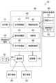
- FIG. 2 is a block diagram illustrating an example of the device operating device according to the first embodiment.
- FIG. 3 is a diagram illustrating an example of screen information for designating an operation target device.
- FIG. 4 is a diagram illustrating an example of screen information for designating operation details.
- FIG. 5 is an explanatory diagram used for explaining detection of neck motion.
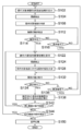
- FIG. 6 is a flowchart showing a flow of processing for a first example of a device operation method using the device operation apparatus of the first embodiment.
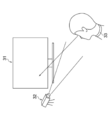
- FIG. 7 is an explanatory diagram used for explanation of line-of-sight detection in the device operating device according to the first embodiment.
- FIG. 1 is a diagram illustrating an overall configuration of an example of an electronic device system according to the first embodiment.
- FIG. 2 is a block diagram illustrating an example of the device operating device according to the first embodiment.
- FIG. 3 is a diagram illustrating an example of
- FIG. 8 is a flowchart showing the flow of processing for the second example of the device operation method using the device operation apparatus of the first embodiment.
- FIG. 9 is a flowchart showing the flow of processing for a third example of the device operation method using the device operation apparatus of the first embodiment.
- FIG. 10 is a block diagram illustrating an example of a device operating device according to the second embodiment.
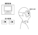
- FIG. 11 is an explanatory diagram used for explaining a field-of-view image and an eye image captured by the head-mounted terminal in the device operating device according to the second embodiment.
- FIG. 12 is an explanatory diagram used for explaining an example of line-of-sight detection and operation determination in the device operating device according to the second embodiment.
- FIG. 13 is a diagram illustrating an overall configuration of an example of an electronic device system when an endoscope apparatus is used as the electronic device.
- FIG. 14 is a block diagram showing a configuration of the electronic device system shown in FIG.
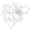
- FIG. 15 is a diagram illustrating a state of observation by the endoscope apparatus.
- FIG. 1 is a diagram illustrating an overall configuration of an example of an electronic device system according to a first embodiment of the present invention
- FIG. 2 is a block diagram illustrating an example of a device operating device according to the first embodiment of the present invention. .
- the electronic device system 10 includes an electronic device 20 that is an operation target device and a device operation device 30 that controls the electronic device 20.
- the device operating device 30 includes a display unit 31 (also referred to as a “display”) that displays to the user, a line-of-sight detection camera 32 that captures the user's face to detect the user's line of sight, and a user's neck.
- a cervical wearing terminal 33 that is mounted and detects the movement of the user's cervix; and a calculation unit 34 that executes various calculations as a main unit that controls the display unit 31, the line-of-sight detection camera 32, and the cervical wearing terminal 33. It consists of
- the display unit 31 is configured by a display device such as a liquid crystal display device.
- the line-of-sight detection camera 32 is arranged in the vicinity of the display unit 31, captures at least the eyes of the user, and generates and outputs an image including an image of the eyes (hereinafter referred to as “user image”).
- user image an image including an image of the eyes
- the extraction may be executed by the function of the line-of-sight detection camera 32, or the extraction unit may be provided with the extraction function.
- a plurality of line-of-sight detection cameras 32 may be provided in order to reliably and stably detect the line of sight.
- the neck wearing terminal 33 is a terminal worn on the user's neck, and as shown in FIG. 1, the neck motion sensor 52 that detects the movement of the user's neck and the vibration of the user's throat at the neck.
- a vibration sensor 54 is provided.
- a sensor device such as a myoelectric sensor, a strain sensor, an acceleration sensor, or the like that detects the motion of the neck muscles is used. Sensor devices other than these may be used. Further, as the “cervical movement”, any of the movement of the cervical muscle, the movement of the cervical bone, and the movement of the cervical surface (that is, the movement of the skin) is detected by the cervical movement sensor 52. May be. Detection may be performed using a plurality of types of sensor devices.
- vibration sensor 54 for example, an acceleration sensor that detects the vibration of the cervical bone is used. Other types of sensors may be used.
- the cervical motion sensor 52 and the vibration sensor 54 may be configured by a single sensor device, and the cervical motion detection and throat vibration detection may be performed by the single sensor device.
- the neck motion sensor 52 and the vibration sensor 54 are configured by a single acceleration sensor, and a signal indicating the motion of the neck is generated by extracting a low frequency component from the output signal of the acceleration sensor. To generate a signal indicating vibration of the throat.
- the calculation unit 34 includes a communication unit 38 that communicates with a plurality of electronic devices 20, a storage unit that stores a program for operation control of the electronic device 20 and information necessary for executing the program. 39 and a CPU (central processing unit) 40 that controls each unit of the device operating device 30 by executing a program stored in the storage unit 39.
- the communication unit 38 includes a communication device that communicates with the electronic device 20.
- FIG. 1 illustrates a case where communication with the electronic device 20 is performed wirelessly, communication with the electronic device 20 may be performed via a local area network or the like. 1 may be communicated with a device outside the arithmetic unit 34 (for example, the database 22), not shown in the drawing, via a local area network or the like.
- the storage unit 39 includes a non-volatile storage device that stores a program and the like, and a readable / writable storage device that is used as a work area of the program.
- the CPU 40 includes a display control unit 41 that performs display control of the display unit 31, a gaze detection unit 42 that detects a user's gaze based on a user image output from the gaze detection camera 32, A motion recognition unit 43 for recognizing the motion of the user's head based on the movement of the user's neck detected by the neck motion sensor 52 of the head-mounted terminal 33, the line of sight detected by the line-of-sight detection unit 42, and the user A determination unit 44 for determining at least one of the operation target device and the operation content for the operation target device based on the movement of the user's head recognized from the movement of the neck of the user, and the vibration sensor of the neck mounting terminal 33
- a voice recognition unit 45 for recognizing the user's voice from the vibration of the user's throat detected by the user's neck by 54 and a device control unit 46 for controlling the electronic device 20 according to the judgment of the judgment unit 44; That.
- the display control unit 41 has a function of causing the display unit 31 to display screen information necessary for a user operation.
- the display control unit 41 operates from a plurality of icons E11 and E12 indicating a plurality of electronic devices 20 (for example, “electronic device A” and “electronic device B”), respectively, to operation target devices (for example, Screen information (hereinafter referred to as “operation target device designation screen information”) for designating an icon indicating “electronic device A”) (for example, icon E11) by line-of-sight input is displayed on the display unit 31.
- operation target device designation screen information for designating an icon indicating “electronic device A”
- icon E11 for example, icon E11
- the display control unit 41 has a plurality of icons E21, E22, which respectively indicate a plurality of functions (for example, “function 1”, “function 2”, and “function 3”).
- Screen information (hereinafter referred to as “function designation screen information”) for designating an icon (eg, icon E21) indicating a function (eg, “function 1”) to be executed by the operation target device from E23 by line-of-sight input is displayed on the display unit 31. To display.
- the display control unit 41 has a plurality of icons respectively indicating a plurality of execution conditions (for example, “execution condition 1”, “execution condition 2”, and “execution condition 3”).
- Screen information (hereinafter referred to as “execution condition designation screen information”) for designating an icon (for example, icon E31) indicating the execution condition of the function to be executed by the operation target device from the line of sight input from E31, E32, and E33. 31 is displayed.
- the “function designation screen information” and the “execution condition designation screen information” are forms of screen information (hereinafter referred to as “operation content designation screen information”) for designating an icon indicating the operation content by line-of-sight input. That is, the “operation content” in this example includes “function” and “execution condition”.
- the detection of the line of sight is performed based on the position of the iris with respect to the eye, with the reference point as the head and the moving point (the portion that moves relative to the reference point) as the iris from the user's eye image. It can. In this case, for example, if the left eye iris is far from the eye, the user is looking at the left side. Conversely, if the left eye is close to the iris, the user is looking at the right side.
- the line of sight can also be detected based on the position of the pupil relative to the position of corneal reflection, with the reference point as the corneal reflection point and the moving point as the pupil. In this case, for example, if the pupil is closer to the outer corner of the eye than the corneal reflection of the left eye, the user looks at the left side. If the pupil is closer to the eye than the corneal reflection, the user is looking at the right side.
- the user's face is irradiated with infrared rays and photographed with an infrared camera.
- the line-of-sight detection unit 42 of this example detects movement of the line of sight (that is, detects the line of sight continuously), and the determination unit 44 of this example determines the operation target device and the operation based on the detected movement of the line of sight Determine the operation details for the target device.
- the determination unit 44 may determine at least one of the operation target device and the operation content based on the detected movement of the line of sight.
- neck tilt which is an operation of tilting the neck
- nodding which is a vertical swing operation of the neck
- swinging which is a horizontal swinging motion of the neck
- the neck muscles are moved by commands from the user's brain that are intended to perform actions such as tilting the head, nodding, and swinging the head.
- the head moves.
- the movement recognition is not performed by detecting the “movement of the head”, but by directly detecting the movement of the neck by the neck movement sensor 52 of the neck wearing terminal 33. Therefore, the motion recognition unit 43 can accurately recognize the motion intended by the user.
- the determination unit 44 determines at least one of the operation target device and the operation content based on the line of sight detected by the line-of-sight detection unit 42, and detects the neck of the neck detected by the neck motion sensor 52 of the neck wearing terminal 33. Make a decision based on the movement. Note that the determination unit 44 of this example makes a determination based on the motion recognized by the motion recognition unit 43 from the detection result of the neck motion sensor 52. It is included in the concept of “determining based on” or “determining determination based on neck movement”.
- the voice recognition unit 45 recognizes the user's voice based on the vibration of the user's throat detected by the user's neck by the vibration sensor 54 of the neck wearing terminal 33.
- the device control unit 46 is an embodiment of the “control unit” in the present invention, and controls the electronic device 20 that is the operation target device according to the determination of the determination unit 44.
- the determination unit 44 determines that “electronic device A” is designated from the operation target device designation screen information shown in FIG. 3, and designates “function 1” from the function designation screen information shown in FIG.
- the communication unit 38 controls the electronic device A that is the operation target device. An instruction to execute function 1 under execution condition 1 is transmitted.
- FIG. 6 is a flowchart showing the flow of processing for a first example of a device operation method using the device operation apparatus 30 of the present embodiment. This process is executed by the CPU 40 according to a program stored in the storage unit 39 in advance.
- step S102 the display control unit 41 displays the operation target device designation screen information on the display unit 31 as shown in FIG.
- the line-of-sight detection unit 42 detects the line of sight of the user. For example, as shown in FIG. 7, when the user is directing his / her line of sight on the screen of the display unit 31, based on the captured image (user image) captured by the line-of-sight detection camera 32, the user A position where the line of sight is directed (line of sight position) is calculated.
- step S108 the determination unit 44 determines the operation target device designated by the user with the line of sight based on the line of sight detected in step S104.
- the neck motion sensor 52 of the neck wearing terminal 33 detects the user's neck motion, and the motion recognition unit 43 recognizes the user's motion.
- step S114 the determination unit 44 determines whether or not the user has performed a confirmation operation (for example, “nodding” shown in FIG. 5B).
- step S114 If it is determined that the confirming operation has not been performed (NO in step S114), the process proceeds to step S116, and the determination unit 44 causes the user to perform the canceling operation (for example, “neck” shown in FIG. 5C). It is determined whether or not “was performed”. If it is determined that the cancel operation has been performed (YES in step S116), the determination result of the operation target device based on the line-of-sight detection result is cleared, and the process returns to step S102. If it is determined that the cancel operation has not been performed (NO in step S116), the process returns to step S112, and the neck motion detection (step S112) and the definite operation determination (step S114) are repeated.
- the canceling operation for example, “neck” shown in FIG. 5C.
- step S114 If it is determined that the confirmation operation has been performed (YES in step S114), the process proceeds to step S122, and the display control unit 41 displays operation content designation screen information on the display unit 31 as shown in FIG. To do.
- the “function designation screen information” shown in FIG. 4A, the “execution condition designation screen information” shown in FIG. 4B, or the screen information that combines both pieces of screen information is the operation content designation screen information. Is displayed.
- step S124 the visual line detection unit 42 detects the user's visual line. That is, the line-of-sight detection unit 42 calculates the position (line-of-sight position) where the user is looking at the line on the screen of the display unit 31 based on the captured image (user image) of the line-of-sight detection camera 32.
- the determination unit 44 determines the operation content designated by the user with the line of sight based on the line of sight detected in step S124. That is, the operation content for the electronic device 20 to be operated is determined.
- the neck motion sensor 52 of the neck wearing terminal 33 detects the movement of the user's neck, and the motion recognition unit 43 recognizes the user's motion.
- the determination unit 44 determines whether or not the user has performed a confirmation operation (for example, “nodding” shown in FIG. 5B).
- step S134 If it is determined that the confirming operation has not been performed (NO in step S134), the process proceeds to step S136, and the determination unit 44 causes the user to perform the canceling operation (for example, “neck” shown in FIG. 5C). It is determined whether or not “was performed”. If it is determined that a cancel operation has been performed (YES in step S136), the operation content determination result based on the line-of-sight detection result is cleared, and the process returns to step S122. If it is determined that the cancel operation has not been performed (NO in step S136), the process returns to step S132, and the neck motion detection (step S132) and the determination operation determination (step S134) are repeated.
- the cancel operation for example, “neck” shown in FIG. 5C.
- step S134 If it is determined that the confirming operation has been performed (YES in step S134), the process proceeds to step S138, and the specified operation content of the specified operation target device is executed.
- step S142 it is determined whether or not to continue the operation on the same electronic device 20 among the plurality of electronic devices 20.
- the process returns to step S122.
- step S144 it is determined whether or not to start an operation on another electronic device 20.
- the process returns to step S102.
- step S144 When the operation on the same or another electronic device 20 is ended (NO in step S144), the process proceeds to step S150 to execute voice processing, thereby generating and outputting a report.
- step S150 Details of the voice processing in step S150 will be described. First, vibration of the throat is detected at the user's neck by the vibration sensor 54 of the neck wearing terminal 33. Next, the voice recognition unit 45 recognizes the user's voice based on the detected vibration of the user's throat. Next, the recognized voice is recorded. That is, it is possible to easily record only the voice of the person wearing the neck wearing terminal 33 without recording surrounding music and voice.
- the sound is recorded in a mode (hereinafter referred to as “internal recording mode”) in which the arithmetic unit 34 that is a main unit of the device operating device 30 is recorded, and an arithmetic unit 34 that is the main unit of the device operating device 30.
- an external recording mode hereinafter referred to as “external recording mode”
- the present invention may be in any case.
- audio data is recorded in the storage unit 39 under the control of the CPU 40.
- the storage unit 39 is a form of “voice recording unit”.
- audio data is output from the communication unit 38 (which is a form of “audio data output unit”), and for example, the audio data is recorded in the database 22.
- the database 22 is a form of “voice recording unit”. For example, voice data is filed and transmitted to the database 22 via a local area network.
- the voice processing (step S150) is performed after the device operation is finished.
- the present invention is not limited, and the voice during the device operation can be input, recognized and recorded.
- instructions and conversations of doctors during the operation are recorded as audio data, which can be used as evidence when a medical accident occurs or used for passing on medical technology.
- step S150 When the generation and output of the report are completed by the voice processing (step S150), this processing is terminated.
- steps S108, S114, S116, S128, S134, and S136 are one form of the “determination step” in the present invention.
- Step S138 is one form of the “control process” in the present invention.
- the line-of-sight detection by the line-of-sight detection unit 42 and the movement of the neck by the neck-mounted terminal 33 are performed at different times, but the line-of-sight detection and the movement of the neck are detected in time series. You can go. Further, the line-of-sight detection and the neck movement detection may be successively performed.
- gaze detection and neck motion detection may be performed simultaneously, but the gaze detection unit 42 of this example starts the neck motion detection by the neck wearing terminal 33. Then, the detection of the line of sight is stopped, and the detection of the line of sight is started when the neck wearing terminal 33 finishes detecting the movement of the neck.
- the gaze detection unit 42 stops the gaze detection when the neck motion detection is started in step S112 and step S132 in FIG. 6, and the gaze detection unit 42 resumes the gaze detection after the neck motion detection is completed.
- FIG. 8 is a flowchart showing the flow of processing for the second example of the device operation method using the device operation apparatus of the present embodiment. This process is executed by the CPU 40 according to a program stored in the storage unit 39 in advance.
- the same steps as those in the first example of the present embodiment shown in FIG. 6 are denoted by the same reference numerals, and only differences will be described below.
- gaze detection and cervical motion detection are performed instead of the gaze detection (step S104, step S124) shown in FIG.
- the neck movement detected by the neck wearing terminal 33 is compared with a threshold (steps S106 and S126), and the detected neck is detected.
- the detection of the line of sight is invalidated.
- the gaze detection in a state where the user's neck is stationary or finely moved is enabled, while the gaze detection in a state where the movement of the user's neck is greatly moved is disabled. This is because when the user's neck moves greatly, the user's head also moves greatly, and as a result, the user's line of sight may move unconsciously, possibly making a determination that does not match the user's intention. Because.
- the detected neck motion when the detected amount of neck motion (that is, the magnitude of the motion vector) is larger than the threshold, the detected neck
- the evaluation value indicating the fluctuation in the direction of motion that is, the direction of the motion vector
- a threshold value that is, as the magnitude of the movement of the user's neck that affects the accuracy of the line-of-sight detection, the magnitude of fluctuation in the direction of the motion vector can be cited in addition to the magnitude of the motion vector.
- “detected cervical movement” is a concept including an evaluation value of a motion vector in addition to the magnitude of the motion vector.
- FIG. 9 is a flowchart showing the flow of processing for a third example of a device operation method using the device operation apparatus of the present embodiment. This process is executed by the CPU 40 according to a program stored in the storage unit 39 in advance.
- the same steps as those in the first example of the present embodiment shown in FIG. 6 and the second example of the present embodiment shown in FIG. 8 are denoted by the same reference numerals, and only differences will be described below.
- gaze detection and neck motion detection are performed instead of the neck motion detection (step S112, step S132) shown in FIGS.
- the operation is a confirmation operation (steps S114 and S134) It is determined whether or not (Step S116, Step S136).
- whether or not to confirm the determination of the operation target device and the operation content and whether or not to cancel the determination of the operation target device and the operation content are determined not only by the detection result of the cervical movement. This is also performed based on the result of eye gaze detection. This is because if it is determined whether or not the user has performed a confirmation or cancellation operation based solely on the movement of the neck, the user performs the confirmation or cancellation operation even if the user moves the neck unconsciously. This is because there is a possibility of misjudging. As a method of avoiding such erroneous determination, a method of changing a determination reference value such as increasing a threshold value to be compared with the detected neck movement can be considered.
- the user's pupil moves up (or The movement of the cervical motion vector becomes larger than the cervical motion determination threshold while the amount of movement of the sight line position on the screen is equal to or less than the sight movement determination threshold. Is detected.
- the user's pupil is moved to the right (or left) when the neck is swung left (or right). By moving, the magnitude of the cervical motion vector is detected to be larger than the cervical motion determination threshold, while the amount of movement of the sight line position on the screen is less than or equal to the sight movement determination threshold.
- FIG. 10 is a block diagram illustrating an example of the device operating device 30 according to the second embodiment. 10, the same components as those of the device operating device 30 of the first embodiment shown in FIG. 2 are denoted by the same reference numerals, and only different points will be described below.
- the head-mounted terminal 60 is a terminal mounted on the user's head as shown in FIG. 11, and includes a field-of-view camera 61 that captures a subject image in the field of view of the user's eyes and acquires a field-of-view image, and the user A line-of-sight detection camera 62 that captures the eyes and obtains an image of the eyes.
- the visual field camera 61 is arranged so as to be positioned in the vicinity of the left eye and / or the right eye when the head-mounted terminal 60 is mounted on the user's head.
- a field camera 61 is disposed in each of the vicinity of the left eye and the vicinity of the right eye, A stereoscopic image composed of the image and the visual field image of the right eye is obtained.
- the line-of-sight detection camera 62 is arranged so that each of the left eye and the right eye becomes an imaging target when the head-mounted terminal 60 is mounted on the user's head.
- a plurality of gaze detection cameras 62 may be provided in order to reliably detect gaze.
- the device operation method using the device operation device 30 of the present embodiment can be executed in substantially the same manner as the processing described with reference to FIG. 6 in the first embodiment.
- the visual field image acquired by the visual field camera 61 of the head-mounted terminal 60 and the visual line detection camera 62 of the head-mounted terminal 60 in the visual line detection by the visual line detection unit 42 (step S104 in FIG. 6). Based on the acquired eye image, the user's line-of-sight position is calculated.
- the head-mounted terminal 60 of this example continues to transmit the visual field image acquired by the visual field camera 61 and the eye image acquired by the visual line detection camera 62 to the calculation unit 34 that is the main unit.
- the field-of-view image and the eye image are transmitted as still images at constant or indefinite time intervals. You may transmit as a moving image at a fixed frame rate.
- the line-of-sight detection unit 42 of the calculation unit 34 calculates the relative positional relationship between the user's eyes and the screen of the display unit 31 based on the field image (both the left eye field image and the right eye field image in this example). To do.
- the line-of-sight detection unit 42 of the calculation unit 34 moves relative to the reference point and the moving point (relative to the reference point) based on the eye image (both the left eye image and the right eye image in this example). Relative position) is calculated.
- the visual line detection camera 62 captures visible light, for example, the eye and / or the corner of the eye is used as a reference point, and the iris is used as a moving point.
- infrared light is captured by the line-of-sight detection camera 62, for example, a corneal reflection point is used as a reference point, and a pupil is used as a moving point.
- the line-of-sight detection unit 42 of the calculation unit 34 is based on the relative positional relationship between the calculated eye and the screen of the display unit 31 and the calculated positional relationship between the reference point and the moving point of the eye.
- the coordinates (the line-of-sight position in the field-of-view image) indicating where the user is looking in the field-of-view image are calculated. That is, the visual field image and the line-of-sight position are associated with each other.
- the line-of-sight position is, for example, a small circular range with a constant radius centered on the (x, y) coordinate.
- the user can select a GUI element (of the three elements from element E21 to element E23 in the figure) that exists in the portion centered on the (x, y) coordinates of the visual field image. It can be determined that the line of sight is directed to the element E21).
- the neck motion sensor 52 of the neck wearing terminal 33 detects the neck motion. Then, since the motion recognition unit 43 recognizes the vertical swing of the user's neck (also referred to as “nodding”), the operation corresponding to the element E21 watched by the user is confirmed.
- gaze detection is performed using the so-called glasses-type head-mounted terminal 60, it is possible to accurately detect the user's gaze position regardless of the user's face orientation or body orientation. become. That is, the user can turn the line of sight naturally. Further, even when the angle of the user's head (face orientation) changes, it is possible to accurately detect the line of sight regardless of the change in the angle of the head.
- FIG. 13 is an external view showing an electronic device system (endoscope system 10) when the endoscope apparatus 100 is used as the electronic device 20 shown in FIG.
- the endoscope main body 110 includes a hand operation unit 102 and an insertion unit 104 connected to the hand operation unit 102.
- the surgeon grasps and operates the hand operation unit 102 and inserts the insertion unit 104 into the body of the subject to perform observation.
- the insertion unit 104 includes a flexible portion 112, a bending portion 114, and a distal end portion 116 in this order from the hand operating portion 102 side.
- the distal end portion 116 is provided with a photographing optical system 130 (see FIG. 14), an illumination unit 123, a water supply nozzle 124, a forceps port 126, and the like.
- either or both visible light and infrared light can be emitted from the illumination lenses 123A and 123B of the illumination unit 123 by operating the operation unit 208 (see FIG. 14). Further, by operating the operation unit 208, cleaning water is discharged from the water supply nozzle 124, and the lens 132 of the photographing optical system 130 and the illumination lenses 123A and 123B can be cleaned.
- a treatment tool (not shown) for tumor removal or excision is inserted into the forceps port 126, and can be advanced and retracted appropriately to perform necessary treatment on the subject.
- a lens 132 of the photographing optical system 130 is disposed on the distal end surface of the distal end portion 116, and a CMOS (Complementary MOS) type imaging device 134, a drive circuit 136, An AFE (Analog Front End) 138 is arranged to output an image signal.
- CMOS Complementary MOS
- An AFE Analog Front End
- the image sensor 134 is a CMOS type image sensor will be described, but the image sensor 134 may be a CCD (Charge-Coupled Device) type.
- An observation image taken in via the lens 132 or the like is formed on the light receiving surface of the image sensor 134 and converted into an electric signal, which is output to the endoscope processor 200 via a signal cable (not shown) and converted into a video signal. Is done. Thereby, an observation image is displayed on the monitor 400 connected to the endoscope processor 200.
- FIG. 15 is a diagram illustrating a state where the insertion unit 104 of the endoscope apparatus 100 is inserted into the subject, and illustrates a state in which an observation image is acquired through the imaging optical system 130.
- reference symbol IA indicates an imaging range
- reference symbol tm indicates a tumor (a portion protruding in black in FIG. 15).
- illumination lenses 123 ⁇ / b> A (for visible light) and 123 ⁇ / b> B (for infrared light) of the illumination unit 123 are provided on the distal end surface of the distal end portion 116 adjacent to the lens 132. Yes.
- An exit end of a light guide 170 which will be described later, is disposed behind the illumination lenses 123A and 123B.
- the light guide 170 is inserted into the insertion unit 104, the hand operation unit 102, and the universal cable 106.
- the incident end is disposed in the light guide connector 108.
- the light source device 300 includes a light source 310, a diaphragm 330, a condenser lens 340, and the like, and makes illumination light incident on the light guide 170.
- the light source 310 includes a visible light source 310A and an infrared light source 310B, and can emit one or both of visible light and infrared light. Accordingly, by connecting the light guide connector 108 (see FIG. 13) to the light source device 300, the illumination light emitted from the light source device 300 is transmitted to the illumination lenses 123A and 123B via the light guide 170, and is used for illumination. The observation range is irradiated from the lenses 123A and 123B.
- the endoscope processor 200 inputs an image signal output from the endoscope apparatus 100 via the image input controller 202, performs necessary image processing in the image processing unit 204, and outputs it via the video output unit 206. To do. Thereby, an observation image is displayed on the monitor 400. These processes are performed under the control of a CPU (Central Processing Unit) 210.
- a CPU Central Processing Unit
- the image processing unit 204 in addition to image processing such as white balance adjustment, switching or superimposing display of an image displayed on the monitor 400, electronic zoom processing, display and switching of an image according to an operation mode, a specific component (for example, a luminance signal) is extracted.
- the endoscope processor 200 includes an operation unit 208.
- the operation unit 208 includes an operation mode setting (not shown), a changeover switch, a water supply instruction button, or the like, and can operate irradiation with visible light or infrared light.
- the operation target device is the endoscope apparatus 100 that is a medical device
- the operation target device may not be a medical device.
- the operation target device in situations where both hands cannot be used freely for operation of portable devices such as smartphones, tablet terminals, game consoles, and device operations such as driving a vehicle, or where there are restrictions on device placement Applicable to equipment operation.
- the operation target device is not limited to one, and may be selected from a plurality of devices based on the line of sight and the movement of the neck.
- the gesture may be performed by moving only the neck without moving the head, The user who becomes the target and the user whose gesture is to be detected may be different.
- DESCRIPTION OF SYMBOLS 10 ... Electronic device system, 20 ... Electronic device, 22 ... Database (one form of audio
Landscapes
- Engineering & Computer Science (AREA)
- Health & Medical Sciences (AREA)
- Theoretical Computer Science (AREA)
- General Engineering & Computer Science (AREA)
- Life Sciences & Earth Sciences (AREA)
- Physics & Mathematics (AREA)
- Human Computer Interaction (AREA)
- General Physics & Mathematics (AREA)
- General Health & Medical Sciences (AREA)
- Biomedical Technology (AREA)
- Surgery (AREA)
- Heart & Thoracic Surgery (AREA)
- Medical Informatics (AREA)
- Veterinary Medicine (AREA)
- Public Health (AREA)
- Animal Behavior & Ethology (AREA)
- Biophysics (AREA)
- Pathology (AREA)
- Molecular Biology (AREA)
- Radiology & Medical Imaging (AREA)
- Physiology (AREA)
- Nuclear Medicine, Radiotherapy & Molecular Imaging (AREA)
- Oral & Maxillofacial Surgery (AREA)
- Dentistry (AREA)
- Audiology, Speech & Language Pathology (AREA)
- Neurology (AREA)
- Computer Vision & Pattern Recognition (AREA)
- Dermatology (AREA)
- Neurosurgery (AREA)
- Optics & Photonics (AREA)
- Computational Linguistics (AREA)
- Acoustics & Sound (AREA)
- Multimedia (AREA)
- User Interface Of Digital Computer (AREA)
- Position Input By Displaying (AREA)
- Endoscopes (AREA)
- Eye Examination Apparatus (AREA)
Abstract
本発明は、ユーザが両手を使えない状況でも容易に操作することができ、且つユーザが意図した操作を的確に検出して実行することができる機器操作装置、機器操作方法、及び電子機器システムを提供する。本発明の機器操作装置は、ユーザの視線を検出する視線検出部(42)と、ユーザの頸部に装着されユーザの頸部の動きを検出する頸部装着端末(33)と、検出された視線及び検出された頸部の動きに基づいて、操作対象機器である電子機器(20)及び操作内容のうちの少なくとも一方を判断する判断部(44)と、判断に従って操作対象機器である電子機器を制御する機器制御部(46)と、を備える。
Description
本発明は機器操作装置、機器操作方法、及び電子機器システムに係り、特にユーザの視線と頸部の動きとにより機器を操作する技術に関する。
各種機器の操作は、ユーザが手や足により行うことが一般的であるが、機器の種類や使用状況によっては、ユーザの動作の制約あるいは機器や操作デバイスの配置の制約が生じる場合がある。例えばスマートフォンやゲーム機等の携帯機器の操作、車両の運転操作、または医療機器の操作では両手が自由にならない場合があり、また医療機器では操作に際して手袋の着脱や手洗い等を要する場合がある。つまり、手や足による操作技術では、円滑に操作を行うことが困難な場合があった。
手や足を用いない操作技術として、視線及びジェスチャによる操作技術が知られている(例えば特許文献1~4を参照)。
特許文献1、2には、ユーザの頭部の撮影画像に基づいてユーザの注視点を検出し、かつユーザの頭部の撮影画像に基づいて頭部の所定の動作(例えば頭部を縦に振るうなずき動作)を検出し、頭部の所定の動作が検出されるとユーザの注視点に対応する操作を確定することが、記載されている。
特許文献3には、ユーザの手の撮像画像に基づいてユーザの手の動作を検出し、指を1本立てている場合には視線位置にカーソルを移動させる処理を開始すること(カーソル追従モードオン)、及び拳を握って指を立てていない場合には視線位置にカーソルを移動させる処理を終了すること(カーソル追従モードオフ)が、記載されている。
特許文献4には、ユーザの頭部に装着できるユニット(視線位置入力部)のカメラの撮像画像に基づいて視線位置を算出し、その視線位置に焦点位置を移動することが、記載されている。また、特許文献4には、ユーザの頭部の位置や角度を検出する磁気センサを用いることも記載されている。
また、音声入力を用いる操作技術が知られている。特許文献5には、表示部に表示されたアイコン(例えば「光量減少」アイコン)をユーザが所定時間以上注視し続けた状態で、更にユーザがフットスイッチを踏んでアイコンの名称(例えば「光量減少」)を音声入力した場合、ユーザの操作を確定してアイコンに対応したアクションを実行することが、記載されている。音声入力には、衣服に装着するピンマイク、頭部に装着するヘッドマイクが用いられる。
しかしながら、ユーザが両手を使えない状況でも容易に操作することができ、且つユーザが意図した操作を的確に検出して実行することができる操作技術は提供されていないといえる。
特許文献1、2に記載の技術では、視線検出により判断した操作をユーザの頭部の所定の動作検出により確定するので、確かに視線検出により判断するだけの場合よりも誤動作が回避される効果を期待することができるにしても、ユーザの頭部を撮影して得られた画像に基づいて頭部の動作を認識しているため、ユーザが意図的に頸部の筋肉を動かしたことに起因する頭部の動きであるのか、あるいは無意識のうちに体が動いたことに起因する頭部の動きであるのか、装置側で的確に判断することは難しい。また、仮に、判断処理を修正し、ユーザが小さな動きあるいは簡単な動きをした場合には装置側で無視し、ユーザが大きな動き(例えば45度以上頭を傾ける動作)あるいは複雑な動きをした場合のみ有効とする判断処理を行うことを想定してみても、ユーザに大きな動作あるいは複雑な動作を強いることになるので、誤動作を回避できてもスムーズな操作を実現することができず、またユーザに疲労を与えることになる。
特許文献3~5に記載の技術でも、ユーザが両手を使えない状況で容易に操作できることと、ユーザが意図した操作を的確に検出して実行することを、両立させることができるとはいえない。
一方、医療ミスの問題が起きているなか、手術の適否を判断するために、医師間の会話を記録に残すことも考えられるが、手術中の手術室では音楽が流れ、また複数の人が係るため、特許文献5の音声入力では周囲の音楽や音声が記録されてしまい、正確に手術の状況を記録することはできない。
本発明はこのような事情に鑑みてなされたもので、ユーザが両手を使えない状況でも容易に操作することができ、且つユーザが意図した操作を的確に検出して実行することができる機器操作装置、機器操作方法、及び電子機器システムを提供することを目的とする。
上述した目的を達成するため、本発明の第1の態様に係る機器操作装置は、ユーザの視線を検出する視線検出部と、ユーザの頸部に装着されユーザの頸部の動きを検出する頸部装着端末と、検出された視線及び検出された頸部の動きに基づいて、操作対象機器及び操作対象機器に対する操作内容のうちの少なくとも一方を判断する判断部と、判断に従って操作対象機器を制御する制御部と、を備える。
本態様によれば、ユーザが両手を使えない状況でも容易に操作することができ、且つユーザが意図した操作を的確に検出して実行することができる。
本発明の第2の態様に係る機器操作装置において、判断部は、検出された視線に基づいて操作対象機器及び操作内容のうちの少なくとも一方を判断し、検出された頸部の動きに基づいて判断を確定する。
本発明の第3の態様に係る機器操作装置において、視線検出部は視線の移動を検出し、判断部は、検出した視線の移動に基づいて、操作対象機器及び操作内容のうちの少なくとも一方を判断する。
本発明の第4の態様に係る機器操作装置において、操作内容は、制御部が操作対象機器に実行させる機能と、機能の実行条件と、を含む。
本発明の第5の態様に係る機器操作装置において、頸部装着端末により検出されたユーザの喉の振動からユーザの音声を認識する音声認識部と、を備える。
本発明の第6の態様に係る機器操作装置において、認識した音声を記録する音声記録部を備える。
本発明の第7の態様に係る機器操作装置において、視線検出部は、頸部装着端末が頸部の動きの検出を開始したら視線の検出を停止し、頸部装着端末が頸部の動きの検出を終了したら視線の検出を開始する。
本発明の第8の態様に係る機器操作装置において、判断部は、検出された頸部の動きが閾値よりも大きい場合に視線の検出を無効にする。
上述した目的を達成するため、本発明の機器操作方法は、ユーザの視線を検出する視線検出部と、ユーザの頸部に装着されユーザの頸部の動きを検出する頸部装着端末と、を備える機器操作装置の機器操作方法であって、検出された視線及び検出された頸部の動きに基づいて、操作対象機器及び操作対象機器に対する操作内容のうちの少なくとも一方を判断する判断工程と、判断に従って操作対象機器を制御する制御工程と、を含む。
上述した目的を達成するため、本発明の電子機器システムは、機器操作装置と、操作対象機器である電子機器と、を含む。
電子機器は、例えば医療機器である。
本発明よれば、ユーザが両手を使えない状況でも容易に操作することができ、且つユーザが意図した操作を的確に検出して実行することができる。
以下、添付図面に従って本発明に係る機器操作装置、機器操作方法、及び電子機器システムの実施形態について説明する。
<第1の実施形態>
図1は、本発明の第1の実施形態における電子機器システムの一例の全体構成を示す図であり、図2は本発明の第1の実施形態における機器操作装置の一例を示すブロック図である。
図1は、本発明の第1の実施形態における電子機器システムの一例の全体構成を示す図であり、図2は本発明の第1の実施形態における機器操作装置の一例を示すブロック図である。
図1に示すように、電子機器システム10は、操作対象機器である電子機器20と、電子機器20を制御する機器操作装置30とを含んで構成されている。
機器操作装置30は、ユーザに対して表示を行う表示部31(「ディスプレイ」ともいう)と、ユーザの視線を検出するためにユーザの顔を撮像する視線検出カメラ32と、ユーザの頸部に装着されユーザの頸部の動きを検出する頸部装着端末33と、表示部31、視線検出カメラ32及び頸部装着端末33を制御する本体ユニットとして各種の演算を実行する演算部34とを含んで構成されている。
表示部31は、液晶表示デバイスなどの表示デバイスによって構成されている。
視線検出カメラ32は、表示部31の近傍に配置され、ユーザの少なくとも目を撮像して目の画像を含む画像(以下「ユーザ画像」という)を生成して出力する。ユーザの顔のうちの目の部分のみを抽出する場合、その抽出を視線検出カメラ32の機能により実行してよいし、演算部34にその抽出の機能を設けてもよい。尚、視線の検出を確実に安定して行うため、視線検出カメラ32を複数設ける構成としてよい。
頸部装着端末33は、ユーザの頸部に装着される端末であり、図1に示すように、ユーザの頸部の動きを検出する頸部動きセンサ52と、頸部においてユーザの喉の振動を検出する振動センサ54を備える。
頸部動きセンサ52として、頸部の筋肉の動きを検出する筋電センサ、歪センサ、加速度センサなどのセンサデバイスを用いる。これら以外のセンサデバイスを用いてよい。また、「頸部の動き」として、頸部の筋肉の動き、頸部の骨の動き、及び頸部の表面の動き(つまり皮膚の動き)のうちのいずれを、頸部動きセンサ52により検出してもよい。複数種類のセンサデバイスを用いて検出を行ってもよい。
振動センサ54として、例えば、頸部の骨の振動を検出する加速度センサを用いる。他の種類のセンサを用いてもよい。
尚、頸部動きセンサ52及び振動センサ54を一つのセンサデバイスにより構成し、その一つのセンサデバイスに頸部の動き検出と喉の振動検出とを行わせてもよい。例えば、頸部動きセンサ52及び振動センサ54を一つの加速度センサで構成し、その加速度センサの出力信号から、低周波数成分を抽出することにより頸部の動きを示す信号を生成し、高周波数成分を抽出することにより喉の振動を示す信号を生成する。
図2に示すように、演算部34は、複数の電子機器20と通信を行う通信部38と、電子機器20の操作制御のためのプログラム及びそのプログラムの実行に必要な情報を記憶する記憶部39と、記憶部39に記憶されたプログラムを実行することにより機器操作装置30の各部を制御するCPU(central processing unit)40とを含んで構成されている。
通信部38は、電子機器20と通信を行う通信デバイスによって構成されている。図1には、無線により電子機器20と通信する場合を図示したが、ローカルエリアネットワークなどを介して有線により電子機器20と通信してもよい。また、図1では図示を省略した、演算部34の外部の装置(例えばデータベース22)と、ローカルエリアネットワークなどを介して通信してよい。
記憶部39は、プログラムなどを記憶する不揮発性の記憶デバイスと、プログラムのワーク領域として使用される読み書き可能な記憶デバイスとを含んで構成されている。
CPU40は、図2に示すように、表示部31の表示制御を行う表示制御部41と、視線検出カメラ32から出力されたユーザ画像に基づいてユーザの視線を検出する視線検出部42と、頸部装着端末33の頸部動きセンサ52で検出されたユーザの頸部の動きに基づいてユーザの頭部の動作を認識する動作認識部43と、視線検出部42で検出された視線、及びユーザの頸部の動きから認識されたユーザの頭部の動作に基づいて、操作対象機器及び操作対象機器に対する操作内容のうちの少なくとも一方を判断する判断部44と、頸部装着端末33の振動センサ54によりユーザの頸部で検出されたユーザの喉の振動からユーザの音声を認識する音声認識部45と、判断部44の判断に従って電子機器20を制御する機器制御部46を備える。
表示制御部41は、表示部31に、ユーザの操作に必要な画面情報を表示させる機能を有する。
表示制御部41は、図3に示すように、複数の電子機器20(例えば「電子機器A」、「電子機器B」とする)をそれぞれ示す複数のアイコンE11、E12から、操作対象機器(例えば「電子機器A」)を示すアイコン(例えばアイコンE11)を視線入力により指定させるための画面情報(以下「操作対象機器指定画面情報」という)を、表示部31に表示させる。
また、表示制御部41は、図4(A)に示すように、複数の機能(例えば「機能1」、「機能2」及び「機能3」とする)をそれぞれ示す複数のアイコンE21、E22、E23から、操作対象機器に実行させる機能(例えば「機能1」)を示すアイコン(例えばアイコンE21)を視線入力により指定させるための画面情報(以下「機能指定画面情報」という)を、表示部31に表示させる。
また、表示制御部41は、図4(B)に示すように、複数の実行条件(例えば「実行条件1」、「実行条件2」及び「実行条件3」とする)をそれぞれ示す複数のアイコンE31、E32、E33から、操作対象機器に実行させる機能の実行条件を示すアイコン(例えばアイコンE31)を視線入力により指定させるための画面情報(以下「実行条件指定画面情報」という)を、表示部31に表示させる。
尚、「機能指定画面情報」及び「実行条件指定画面情報」は、操作内容を示すアイコンを視線入力により指定させるための画面情報(以下「操作内容指定画面情報」という)の一形態である。つまり、本例の「操作内容」には、「機能」及び「実行条件」が含まれる。
次に、視線検出部42の視線検出について説明する。
視線(注視点)の検出は、ユーザの目の画像から、基準点を目頭、動点(基準点に対して相対的に動く部分)を虹彩とし、目頭に対する虹彩の位置に基づいて行うことができる。この場合例えば、左目の虹彩が目頭から離れていれば、ユーザは左側を見ている。逆に左目の目頭と虹彩が近ければ、ユーザは右側を見ている。
尚、視線の検出は、基準点を角膜反射点とし、動点を瞳孔にして、角膜反射の位置に対する瞳孔の位置に基づいて行うこともできる。この場合例えば、左目の角膜反射よりも瞳孔が目尻側にあれば、ユーザは左側を見ている。角膜反射よりも瞳孔が目頭側にあれば、ユーザは右側を見ている。この方式を用いる場合、ユーザの顔に赤外線を照射して赤外線カメラで撮影する。
本例の視線検出部42は、視線の移動を検出し(つまり視線を連続して検出し)、本例の判断部44は、検出された視線の移動に基づいて、操作対象機器と、操作対象機器に対する操作内容とを判断する。判断部44により、操作対象機器と操作内容のうちの少なくとも一方を、検出した視線の移動に基づいて判断してもよい。
次に、動作認識部43の動作認識について、具体例を説明する。
動作認識部43により認識される動作として、例えば、図5(A)に示す「首傾げ」(首を傾ける動作である)、図5(B)に示す「うなずき」(首の縦振り動作である)、図5(C)に示す「首振り」(首の横振り動作である)が挙げられる。つまり、「首傾げ」、「うなずき」、「首振り」といった動作を意図したユーザの脳からの指令により頸部の筋肉が動かされ、その結果として頭部が動くが、頸部の動きの結果である「頭部の動き」を検出して動作認識を行うのではなく、頸部装着端末33の頸部動きセンサ52により「頸部の動き」を直接的に検出して動作認識を行う。よって、動作認識部43は、ユーザが意図した動作を的確に認識することが可能である。
判断部44は、視線検出部42により検出された視線に基づいて操作対象機器及び操作内容のうちの少なくとも一方を判断し、頸部装着端末33の頸部動きセンサ52で検出された頸部の動きに基づいて判断を確定する。尚、本例の判断部44は、頸部動きセンサ52の検出結果から動作認識部43により認識された動作に基づいて判断を行っており、このような場合も本発明における「頸部の動きに基づいて判断する」あるいは「頸部の動きに基づいて判断を確定する」の概念に含まれる。
音声認識部45は、頸部装着端末33の振動センサ54によりユーザの頸部により検出されるユーザの喉の振動に基づいて、ユーザの音声を認識する。
機器制御部46は、本発明における「制御部」の一形態であり、判断部44の判断に従って、操作対象機器である電子機器20を制御する。
例えば、判断部44により、図3に示した操作対象機器指定画面情報から「電子機器A」が指定されたと判断され、図4(A)に示した機能指定画面情報から「機能1」が指定されたと判断され、かつ図4(B)に示した実行条件指定画面情報から「実行条件1」が指定されたと判断された場合、通信部38により、操作対象機器である電子機器Aに対して機能1を実行条件1において実行するという指示を送信する。
図6は、本実施形態の機器操作装置30を用いた機器操作方法の第1の例について処理の流れを示すフローチャートである。本処理は、CPU40により、記憶部39に予め記憶されたプログラムに従って、実行される。
本処理がスタートすると、まず、ステップS102で、表示制御部41により、図3に示したように、表示部31に操作対象機器指定画面情報を表示する。
次に、ステップS104に進んで、視線検出部42により、ユーザの視線を検出する。例えば、図7に示すようにユーザが表示部31の画面上に視線を向けている場合、視線検出カメラ32により撮像された撮像画像(ユーザ画像)に基づいて、表示部31の画面においてユーザが視線を向けている位置(視線位置)が算出される。
次に、ステップS108に進んで、判断部44により、ステップS104で検出された視線に基づいて、ユーザが視線により指定した操作対象機器を判断する。
次に、ステップS112に進んで、頸部装着端末33の頸部動きセンサ52によりユーザの頸部の動きを検出し、動作認識部43によりユーザの動作を認識する。
次に、ステップS114に進んで、判断部44により、ユーザが確定操作の動作(例えば図5(B)に示した「うなずき」)を行ったか否かを判断する。
確定操作が行われていないと判断された場合(ステップS114でNOの場合)、ステップS116に進んで、判断部44により、ユーザが取消操作の動作(例えば図5(C)に示した「首振り」)を行ったか否かを判断する。取消操作が行われたと判断された場合(ステップS116でYESの場合)、視線検出結果に基づく操作対象機器の判断結果をクリアして、ステップS102に戻る。取消操作も行われていないと判断された場合(ステップS116でNOの場合)、ステップS112に戻り、頸部の動き検出(ステップS112)、確定操作判断(ステップS114)を繰り返す。
確定操作が行われたと判断された場合(ステップS114でYESの場合)、ステップS122に進んで、表示制御部41により、図4に示したように、表示部31に操作内容指定画面情報を表示する。例えば、図4(A)に示した「機能指定画面情報」又は図4(B)に示した「実行条件指定画面情報」、あるいは両方の画面情報を組み合わせた画面情報が、操作内容指定画面情報として表示される。
次に、ステップS124に進んで、視線検出部42により、ユーザの視線を検出する。つまり、視線検出部42により、視線検出カメラ32の撮像画像(ユーザ画像)に基づいて、表示部31の画面においてユーザが視線を向けている位置(視線位置)を算出する。
次に、ステップS128に進んで、判断部44により、ステップS124で検出された視線に基づいて、ユーザが視線により指定した操作内容を判断する。つまり、操作対象の電子機器20に対する操作内容を判断する。
次に、ステップS132に進んで、頸部装着端末33の頸部動きセンサ52によりユーザの頸部の動きを検出し、動作認識部43によりユーザの動作を認識する。
次に、ステップS134に進んで、判断部44により、ユーザが確定操作の動作(例えば図5(B)に示した「うなずき」)を行ったか否かを判断する。
確定操作が行われていないと判断された場合(ステップS134でNOの場合)、ステップS136に進んで、判断部44により、ユーザが取消操作の動作(例えば図5(C)に示した「首振り」)を行ったか否かを判断する。取消操作が行われたと判断された場合(ステップS136でYESの場合)、視線検出結果に基づく操作内容の判断結果をクリアして、ステップS122に戻る。取消操作も行われていないと判断された場合(ステップS136でNOの場合)、ステップS132に戻り、頸部の動き検出(ステップS132)、確定操作判断(ステップS134)を繰り返す。
確定操作が行われたと判断された場合(ステップS134でYESの場合)、ステップS138に進んで、指定された操作対象機器の指定された操作内容を実行する。
次に、ステップS142に進んで、複数の電子機器20のうちの同じ電子機器20に対する操作を継続するか否かを判断する。同じ電子機器20に対する操作を継続する場合(ステップS142でYESの場合)、ステップS122に戻る。また、ステップS144により、他の電子機器20に対する操作を開始するか否かを判断する。他の電子機器20に対する操作を開始する場合(ステップS144でYESの場合)、ステップS102に戻る。
同一及び他の電子機器20に対する操作を終了する場合(ステップS144でNOの場合)、ステップS150に進んで音声処理を実行することにより、レポートの生成及び出力を行う。
ステップS150の音声処理の詳細について説明する。まず、頸部装着端末33の振動センサ54により、ユーザの頸部で喉の振動を検出する。次に、音声認識部45により、検出されたユーザの喉の振動に基づいて、ユーザの音声を認識する。次に、認識した音声を記録する。つまり、周囲の音楽や音声を記録することなく頸部装着端末33を装着した人の音声のみを容易に記録することができる。
音声を記録する態様には、機器操作装置30の本体ユニットである演算装置34の内部で記録する態様(以下「内部記録態様」という)と、機器操作装置30の本体ユニットである演算装置34の外部で記録する態様(以下「外部記録態様」)とがあり、本発明はいずれの場合であってもよい。内部記録態様では、CPU40の制御により、例えば記憶部39に音声のデータを記録する。この例では記憶部39が「音声記録部」の一形態である。外部記録態様では、通信部38(「音声データ出力部」の一形態である)から音声のデータを出力し、例えばデータベース22に音声のデータを記録する。この例ではデータベース22が「音声記録部」の一形態である。例えば、音声のデータをファイル化し、データベース22に対し、ローカルエリアネットワークを介して送信する。
また、図6では機器操作終了後に音声処理(ステップS150)を行っているが、このような場合に本発明は限定されず、機器操作中の音声を入力、認識及び記録することができる。例えば、手術中の医師等の指示や会話を音声のデータとして記録に残し、医療事故が発生した場合の証拠として活用したり、医療技術の伝承に活用できるようにする。
音声処理(ステップS150)によりレポートの生成及び出力が終了すると、本処理を終了する。
図6において、ステップS108、S114、S116、S128、S134及びS136は、本発明における「判断工程」の一形態である。また、ステップS138は、本発明における「制御工程」の一形態である。
尚、図6では、視線検出部42による視線検出と頸部装着端末33による頸部の動き検出とが異なる時機に行われているが、視線検出及び頸部の動き検出とを時系列で並行して行ってよい。また視線検出及び頸部の動き検出をそれぞれ連続して行ってよい。このような並行制御を行う場合、視線検出及び頸部の動き検出が同時に実行される可能性があるが、本例の視線検出部42は、頸部装着端末33が頸部の動き検出を開始したら視線の検出を停止し、頸部装着端末33が頸部の動き検出を終了したら視線の検出を開始する。例えば、図6のステップS112、ステップS132で頸部の動き検出が開始されたときに視線検出部42に視線検出を停止させ、頸部の動き検出が終了したら視線検出部42に視線検出を再開させる。
図8は、本実施形態の機器操作装置を用いた機器操作方法の第2の例について処理の流れを示すフローチャートである。本処理は、CPU40により、記憶部39に予め記憶されたプログラムに従って、実行される。図6に示した本実施形態の第1の例と同じステップには同じ符号を付してあり、以下では相違点のみ説明する。
本例では、図6に示した視線検出(ステップS104、ステップS124)の代わりに、視線検出及び頸部の動き検出(ステップS104A、ステップS124A)を行う。この視線検出及び頸部の動き検出(ステップS104A、ステップS124A)の後に、頸部装着端末33で検出された頸部の動きと閾値とを比較し(ステップS106、ステップS126)、検出された頸部の動きが閾値よりも大きい場合に視線の検出を無効にする。
つまり、本例では、ユーザの頸部が静止又は微動の状態での視線検出を有効にする一方で、ユーザの頸部の動きが大きく動く状態での視線検出を無効にする。なぜなら、ユーザの頸部が大きく動く状態では、ユーザの頭も大きく動き、その結果としてユーザの視線が無意識のうちに大きく動く可能性があり、ユーザの意図に合わない判断をする可能性があるからである。
ここで、「検出された頸部の動きが閾値よりも大きい場合」には、検出された頸部の動きの量(つまり動きベクトルの大きさ)が閾値よりも大きい場合、検出された頸部の動きの方向(つまり動きベクトルの方向)の変動を示す評価値が閾値よりも大きい場合、などが挙げられる。つまり、視線検出の精度に影響するユーザの頸部の動きの大きさとして、動きベクトルの大きさ以外に、動きベクトルの方向の変動の大きさが挙げられる。言い換えると、「検出された頸部の動き」は、動きベクトルの大きさ以外に、その動きベクトルの評価値を含む概念である。
図9は、本実施形態の機器操作装置を用いた機器操作方法の第3の例について処理の流れを示すフローチャートである。本処理は、CPU40により、記憶部39に予め記憶されたプログラムに従って、実行される。図6に示した本実施形態の第1の例及び図8に示した本実施形態の第2の例と同じステップには同じ符号を付してあり、以下では相違点のみ説明する。
本例では、図6及び図8に示した頸部の動き検出(ステップS112、ステップS132)の代わりに、視線検出及び頸部の動き検出(ステップS112A、ステップS132A)を行う。この視線検出及び頸部の動き検出(ステップS112A、ステップS132A)による視線検出及び頸部の動き検出の結果に基づいて、確定操作か否かの判断(ステップS114、ステップS134)、及び取消操作か否かの判断(ステップS116、ステップS136)を行う。
つまり、本例では、操作対象機器及び操作内容の判断の確定を行うか否か、並びに操作対象機器及び操作内容の判断の取消を行うか否かを、頸部の動きの検出結果のみでなく視線の検出結果にも基づいて行う。なぜなら、単に頸部の動きのみに基づいてユーザが確定操作又は取消操作を行ったか否かを判断すると、ユーザが無意識のうちに頸部を動かした場合にもユーザが確定操作又は取消操作を行ったと誤判断する可能性があるからである。このような誤判断を回避する方法として、検出された頸部の動きと比較する閾値を大きくするなどの判定基準値を変更する方法も考えられる。しかし、誤判断回避のためにユーザにより大きな頸部の動きを強いることになると、即ち無理な動作をユーザに強要すると、スムーズな操作ができないことになり、ユーザの疲労にもつながる。そこで、ユーザが表示部31の画面上のGUI(graphical user interface)要素(例えばボタン)を注視している状態で頸部を動かした場合には頸部の動きに関わらず表示部31の画面上の視線位置がほぼ一定又は微動の範囲内に収まるという特性を利用して判断を行う。
例えば、首の縦振り(うなずき)であるか否かを判定することによりユーザが確定操作を行ったか否かを判断する場合、首を下(又は上)に振るとユーザの瞳が上(又は下)に移動することにより、頸部の動きベクトルの大きさが頸部の動き判定用の閾値よりも大きくなる一方で画面上の視線位置の移動量が視線移動判定用の閾値以下になることを検出する。また、首の横振りであるか否かを判定することによりユーザが取消操作を行ったか否かを判断する場合、首を左(又は右)に振るとユーザの瞳が右(又は左)に移動することにより、頸部の動きベクトルの大きさが頸部の動き判定用の閾値よりも大きくなる一方で画面上の視線位置の移動量が視線移動判定用の閾値以下になることを検出する。
<第2の実施形態>
図10は、第2の実施形態における機器操作装置30の一例を示すブロック図である。図10において、図2に示した第1の実施形態の機器操作装置30と同じ構成要素には同じ符号を付してあり、以下では異なる点のみ説明する。
図10は、第2の実施形態における機器操作装置30の一例を示すブロック図である。図10において、図2に示した第1の実施形態の機器操作装置30と同じ構成要素には同じ符号を付してあり、以下では異なる点のみ説明する。
頭部装着端末60は、図11に示すようにユーザの頭部に装着される端末であり、ユーザの目の視野内に存在する被写体を撮像して視野画像を取得する視野カメラ61と、ユーザの目を撮像して目の画像を取得する視線検出カメラ62を備える。視野カメラ61は、頭部装着端末60がユーザの頭部に装着されたときに左目及び/又は右目の近傍に位置するように配置される。本例では、ユーザの左目及び右目と表示部31との相対的な三次元の位置関係を算出可能とするため、左目の近傍及び右目の近傍のそれぞれに視野カメラ61を配置し、左目の視野画像と右目の視野画像とからなる立体視画像を取得する構成としている。視線検出カメラ62は、頭部装着端末60がユーザの頭部に装着されたときに左目及び右目のそれぞれが撮像対象となるように配置される。視線の検出を確実に安定して行うために複数の視線検出カメラ62(例えば左目撮像用の視線検出カメラと右目撮像用の視線検出カメラの二台)を設けてよい。
本実施形態の機器操作装置30を用いた機器操作方法は、第1実施形態で図6を用いて説明した処理とほぼ同様に実行することができる。第2実施形態では、視線検出部42による視線検出(図6のステップS104)において、頭部装着端末60の視野カメラ61により取得された視野画像と、頭部装着端末60の視線検出カメラ62により取得された目の画像とに基づいて、ユーザの視線位置を算出する。
本例の頭部装着端末60は、視野カメラ61により取得された視野画像と視線検出カメラ62により取得した目の画像とを、本体ユニットである演算部34に対して送信し続ける。例えば、視野画像及び目の画像を静止画として、一定あるいは不定の時間間隔で送信する。動画として一定のフレームレートで送信してもよい。
演算部34の視線検出部42は、視野画像(本例では左目の視野画像及び右目の視野画像の両方)に基づいて、ユーザの目と表示部31の画面との相対的な位置関係を算出する。また、演算部34の視線検出部42は、目の画像(本例では左目の画像及び右目の画像の両方)に基づいて、目の基準点と動点(基準点に対して相対的に動く部分)との相対的な位置関係を算出する。視線検出カメラ62で可視光の撮像を行う場合、例えば、目頭及び/又は目尻を基準点とし、虹彩を動点とする。視線検出カメラ62により赤外光の撮像を行う場合、例えば、角膜反射点を基準点とし、瞳孔を動点とする。
次に、演算部34の視線検出部42は、算出された目と表示部31の画面との相対的な位置関係、及び算出された目の基準点と動点との位置関係に基づいて、視野画像のうちのどこをユーザが見ているかを示す座標(視野画像における視線位置である)を算出する。つまり、視野画像と視線位置との対応付けを行う。
図12(A)に示すように、視野画像の横方向をX方向として縦方向をY方向とした場合、視線位置は、(x,y)座標を中心とする例えば一定半径の小さな円形の範囲として表される。つまり、図12(B)に示すように、ユーザは視野画像のうちの(x,y)座標を中心とした部分に存在するGUI要素(図では要素E21から要素E23の三つの要素のうちの要素E21)に視線を向けていると判断することができる。そのGUI要素をユーザが注視している状態で、図12(C)に示すように、ユーザが首を縦に振ると、頸部装着端末33の頸部動きセンサ52により頸部の動きが検出され、動作認識部43によりユーザの首の縦振り(「うなずき」ともいう)が認識されるので、ユーザが注視した要素E21に対応した操作が確定する。
本実施形態によれば、いわゆるメガネ型の頭部装着端末60を用いて視線検知を行うので、ユーザの顔の向きや体の向きに依らず、ユーザの視線位置を正確に検出することが可能になる。つまり、ユーザは視線を自然に向けることができる。また、ユーザの頭部の角度(顔の向き)が変わった場合でも、頭部の角度の変化に関わらず正確に視線検出を行うことができる。
<医用システムへの適用例>
図13は、図1に示した電子機器20として内視鏡装置100を用いる場合の電子機器システム(内視鏡システム10)を示す外観図である。
図13は、図1に示した電子機器20として内視鏡装置100を用いる場合の電子機器システム(内視鏡システム10)を示す外観図である。
≪内視鏡本体の構成≫
内視鏡本体110は、手元操作部102と、この手元操作部102に連設される挿入部104とを備える。術者は手元操作部102を把持して操作し、挿入部104を被験者の体内に挿入して観察を行う。挿入部104は、手元操作部102側から順に、軟性部112、湾曲部114、先端部116で構成されている。先端部116には、撮影光学系130(図14参照)、照明部123、送水ノズル124、鉗子口126等が設けられる。
内視鏡本体110は、手元操作部102と、この手元操作部102に連設される挿入部104とを備える。術者は手元操作部102を把持して操作し、挿入部104を被験者の体内に挿入して観察を行う。挿入部104は、手元操作部102側から順に、軟性部112、湾曲部114、先端部116で構成されている。先端部116には、撮影光学系130(図14参照)、照明部123、送水ノズル124、鉗子口126等が設けられる。
観察または処置の際には、操作部208(図14参照)の操作により、照明部123の照明用レンズ123A,123Bから可視光及び赤外光のいずれか、または両方を照射することができる。また操作部208の操作により、送水ノズル124から洗浄水が放出されて、撮影光学系130のレンズ132及び、照明用レンズ123A,123Bを洗浄することができる。鉗子口126には腫瘍摘出または切除のための図示せぬ処置具が挿通され、適宜進退して被検体に必要な処置を施せるようになっている。
図14に示すように、先端部116の先端面には撮影光学系130のレンズ132が配設されており、このレンズ132の奥にCMOS(Complementary MOS)型の撮像素子134、駆動回路136、AFE(Analog Front End)138が配設されて、画像信号を出力するようになっている。本実施形態では撮像素子134がCMOS型の撮像素子である場合について説明するが、撮像素子134はCCD(Charge Coupled Device)型でもよい。
レンズ132等を介して取り込まれた観察像は撮像素子134の受光面に結像されて電気信号に変換され、不図示の信号ケーブルを介して内視鏡プロセッサ200に出力されて映像信号に変換される。これにより、内視鏡プロセッサ200に接続されたモニタ400に観察画像が表示される。
≪観察画像の表示≫
図15は内視鏡装置100の挿入部104を被検体内に挿入した状態を示す図であり、撮影光学系130を介して観察画像を取得する様子を示している。図15中、参照符号IAは撮影範囲を示し、参照符号tmは腫瘍(図15中黒色で隆起している部分)を示す。
図15は内視鏡装置100の挿入部104を被検体内に挿入した状態を示す図であり、撮影光学系130を介して観察画像を取得する様子を示している。図15中、参照符号IAは撮影範囲を示し、参照符号tmは腫瘍(図15中黒色で隆起している部分)を示す。
図13~図15に示すように、先端部116の先端面には、レンズ132に隣接して照明部123の照明用レンズ123A(可視光用)、123B(赤外光用)が設けられている。照明用レンズ123A、123Bの奥には、後述するライトガイド170の射出端が配設され、このライトガイド170が挿入部104、手元操作部102、及びユニバーサルケーブル106に挿通され、ライトガイド170の入射端がライトガイドコネクタ108内に配置される。
≪光源装置の構成≫
図14に示すように、光源装置300は、光源310、絞り330、及び集光レンズ340等から構成されており、照明用の光をライトガイド170に入射させる。光源310は、可視光源310A及び赤外光源310Bを備えており、可視光及び赤外線の一方または両方を照射可能である。これにより、ライトガイドコネクタ108(図13参照)を光源装置300に連結することによって、光源装置300から照射された照明光がライトガイド170を介して照明用レンズ123A、123Bに伝送され、照明用レンズ123A、123Bから観察範囲に照射される。
図14に示すように、光源装置300は、光源310、絞り330、及び集光レンズ340等から構成されており、照明用の光をライトガイド170に入射させる。光源310は、可視光源310A及び赤外光源310Bを備えており、可視光及び赤外線の一方または両方を照射可能である。これにより、ライトガイドコネクタ108(図13参照)を光源装置300に連結することによって、光源装置300から照射された照明光がライトガイド170を介して照明用レンズ123A、123Bに伝送され、照明用レンズ123A、123Bから観察範囲に照射される。
≪内視鏡プロセッサの構成≫
次に、図14に基づき内視鏡プロセッサ200の構成を説明する。内視鏡プロセッサ200は、内視鏡装置100から出力される画像信号を、画像入力コントローラ202を介して入力し、画像処理部204において必要な画像処理を行ってビデオ出力部206を介して出力する。これによりモニタ400に観察画像が表示される。これらの処理はCPU(Central Processing Unit;中央処理装置)210の制御下で行われる。画像処理部204では、ホワイトバランス調整等の画像処理の他、モニタ400に表示する画像の切替または重畳表示、電子ズーム処理、操作モードに応じた画像の表示及び切替、画像信号からの特定成分(例えば輝度信号)の抽出等を行う。
次に、図14に基づき内視鏡プロセッサ200の構成を説明する。内視鏡プロセッサ200は、内視鏡装置100から出力される画像信号を、画像入力コントローラ202を介して入力し、画像処理部204において必要な画像処理を行ってビデオ出力部206を介して出力する。これによりモニタ400に観察画像が表示される。これらの処理はCPU(Central Processing Unit;中央処理装置)210の制御下で行われる。画像処理部204では、ホワイトバランス調整等の画像処理の他、モニタ400に表示する画像の切替または重畳表示、電子ズーム処理、操作モードに応じた画像の表示及び切替、画像信号からの特定成分(例えば輝度信号)の抽出等を行う。
また、内視鏡プロセッサ200は操作部208を備えている。操作部208は図示せぬ操作モード設定、切替スイッチまたは送水指示ボタン等を備えており、また可視光または赤外光の照射を操作することができる。
<その他>
図13を用いて、操作対象機器が医療機器である内視鏡装置100である場合について説明したが、本発明において操作対象機器は医療機器でなくてもよい。医療機器の他にも、スマートフォン、タブレット端末、ゲーム機等の携帯機器の操作や、車両の運転等の機器操作のために両手を自由に使えない状況や、機器配置に制約がある状況での機器操作に適用できる。また、操作対象機器は1つに限られず、複数の機器から視線及び頸部の動きに基づいて選択するようにしてもよい。また本発明において、操作対象機器や機器の使用状況、操作の種類や重要度等によってはジェスチャを頭部を動かさないで頸部のみを動かす動作で行うようにしてもよいし、視線検出の対象となるユーザとジェスチャ検出の対象となるユーザを別人としてもよい。
図13を用いて、操作対象機器が医療機器である内視鏡装置100である場合について説明したが、本発明において操作対象機器は医療機器でなくてもよい。医療機器の他にも、スマートフォン、タブレット端末、ゲーム機等の携帯機器の操作や、車両の運転等の機器操作のために両手を自由に使えない状況や、機器配置に制約がある状況での機器操作に適用できる。また、操作対象機器は1つに限られず、複数の機器から視線及び頸部の動きに基づいて選択するようにしてもよい。また本発明において、操作対象機器や機器の使用状況、操作の種類や重要度等によってはジェスチャを頭部を動かさないで頸部のみを動かす動作で行うようにしてもよいし、視線検出の対象となるユーザとジェスチャ検出の対象となるユーザを別人としてもよい。
本発明は、上述した実施形態には限定されず、本発明の主旨を逸脱しない範囲で種々の変形が可能であることは言うまでもない。
10…電子機器システム、20…電子機器、22…データベース(音声記録部の一形態)、30…機器操作装置、31…表示部、32…視線検出カメラ、33…頸部装着端末、34…演算部、38…通信部、39…記憶部(音声記録部の一形態)、40…CPU、41…表示制御部、42…視線検出部、43…動作認識部、44…判断部、45…音声認識部、46…機器制御部、52…頸部動きセンサ、54…振動センサ、60…頭部装着端末、61…視野カメラ、62…視線検出カメラ
Claims (11)
- ユーザの視線を検出する視線検出部と、
前記ユーザの頸部に装着され前記ユーザの頸部の動きを検出する頸部装着端末と、
前記検出された視線及び前記検出された頸部の動きに基づいて、操作対象機器及び前記操作対象機器に対する操作内容のうちの少なくとも一方を判断する判断部と、
前記判断に従って前記操作対象機器を制御する制御部と、
を備える機器操作装置。 - 前記判断部は、
前記検出された視線に基づいて前記操作対象機器及び前記操作内容のうちの少なくとも一方を判断し、
前記検出された頸部の動きに基づいて前記判断を確定する、請求項1に記載の機器操作装置。 - 前記視線検出部は前記視線の移動を検出し、
前記判断部は、前記検出した視線の移動に基づいて、前記操作対象機器及び前記操作内容のうちの少なくとも一方を判断する、請求項1または2に記載の機器操作装置。 - 前記操作内容は、前記制御部が前記操作対象機器に実行させる機能と、前記機能の実行条件と、を含む、請求項1から3のいずれか1項に記載の機器操作装置。
- 前記頸部装着端末により検出された前記ユーザの喉の振動から前記ユーザの音声を認識する音声認識部と、を備える請求項1から4のいずれか1項に記載の機器操作装置。
- 前記認識した音声を記録する音声記録部を備える請求項5に記載の機器操作装置。
- 前記視線検出部は、前記頸部装着端末が前記頸部の動きの検出を開始したら前記視線の検出を停止し、前記頸部装着端末が頸部の動きの検出を終了したら前記視線の検出を開始する、請求項1から6のいずれか1項に記載の機器操作装置。
- 前記判断部は、前記検出された頸部の動きが閾値よりも大きい場合に前記視線の検出を無効にする、
請求項1から7のいずれか1項に記載の機器操作装置。 - ユーザの視線を検出する視線検出部と、前記ユーザの頸部に装着され前記ユーザの頸部の動きを検出する頸部装着端末と、を備える機器操作装置の機器操作方法であって、
前記検出された視線及び前記検出された頸部の動きに基づいて、操作対象機器及び前記操作対象機器に対する操作内容のうちの少なくとも一方を判断する判断工程と、
前記判断に従って前記操作対象機器を制御する制御工程と、
を含む機器操作方法。 - 請求項1から8のいずれか1項に記載の機器操作装置と、
前記操作対象機器である電子機器と、
を含む電子機器システム。 - 前記電子機器は医療機器である、請求項10に記載の電子機器システム。
Priority Applications (3)
| Application Number | Priority Date | Filing Date | Title |
|---|---|---|---|
| EP16841280.7A EP3346368B1 (en) | 2015-09-04 | 2016-07-07 | Device, method and system for control of a target apparatus |
| JP2017537625A JP6507252B2 (ja) | 2015-09-04 | 2016-07-07 | 機器操作装置、機器操作方法、及び電子機器システム |
| US15/898,368 US10585476B2 (en) | 2015-09-04 | 2018-02-16 | Apparatus operation device, apparatus operation method, and electronic apparatus system |
Applications Claiming Priority (2)
| Application Number | Priority Date | Filing Date | Title |
|---|---|---|---|
| JP2015-174575 | 2015-09-04 | ||
| JP2015174575 | 2015-09-04 |
Related Child Applications (1)
| Application Number | Title | Priority Date | Filing Date |
|---|---|---|---|
| US15/898,368 Continuation US10585476B2 (en) | 2015-09-04 | 2018-02-16 | Apparatus operation device, apparatus operation method, and electronic apparatus system |
Publications (1)
| Publication Number | Publication Date |
|---|---|
| WO2017038248A1 true WO2017038248A1 (ja) | 2017-03-09 |
Family
ID=58186990
Family Applications (1)
| Application Number | Title | Priority Date | Filing Date |
|---|---|---|---|
| PCT/JP2016/070073 Ceased WO2017038248A1 (ja) | 2015-09-04 | 2016-07-07 | 機器操作装置、機器操作方法、及び電子機器システム |
Country Status (4)
| Country | Link |
|---|---|
| US (1) | US10585476B2 (ja) |
| EP (1) | EP3346368B1 (ja) |
| JP (1) | JP6507252B2 (ja) |
| WO (1) | WO2017038248A1 (ja) |
Cited By (3)
| Publication number | Priority date | Publication date | Assignee | Title |
|---|---|---|---|---|
| JP6425860B1 (ja) * | 2018-01-18 | 2018-11-21 | 三菱電機株式会社 | 機器操作装置、機器操作システムおよび機器操作方法 |
| JP2021060824A (ja) * | 2019-10-07 | 2021-04-15 | 株式会社Fuji | 基板作業機 |
| JP2023115808A (ja) * | 2022-02-08 | 2023-08-21 | キヤノン株式会社 | 電子機器、電子機器の制御方法、プログラム、および記録媒体 |
Families Citing this family (2)
| Publication number | Priority date | Publication date | Assignee | Title |
|---|---|---|---|---|
| JP2018198685A (ja) * | 2017-05-26 | 2018-12-20 | ソニー株式会社 | 制御装置、制御方法、および手術システム |
| JP7507482B2 (ja) * | 2020-10-29 | 2024-06-28 | パナソニックオートモーティブシステムズ株式会社 | 視線入力装置 |
Citations (4)
| Publication number | Priority date | Publication date | Assignee | Title |
|---|---|---|---|---|
| JPH04372012A (ja) * | 1991-06-20 | 1992-12-25 | Fuji Xerox Co Ltd | 入力装置 |
| JPH10198476A (ja) * | 1997-01-07 | 1998-07-31 | Nec Corp | 頭部動き検出装置 |
| JP2008046802A (ja) * | 2006-08-14 | 2008-02-28 | Advanced Telecommunication Research Institute International | インタラクション情報出力装置、インタラクション情報出力方法、及びプログラム |
| JP2009251658A (ja) * | 2008-04-01 | 2009-10-29 | Fujifilm Corp | 携帯型電子装置及びその制御方法 |
Family Cites Families (17)
| Publication number | Priority date | Publication date | Assignee | Title |
|---|---|---|---|---|
| JP2000163196A (ja) * | 1998-09-25 | 2000-06-16 | Sanyo Electric Co Ltd | ジェスチャ認識装置及びジェスチャ認識機能を有する指示認識装置 |
| JP2001100903A (ja) | 1999-09-28 | 2001-04-13 | Sanyo Electric Co Ltd | 視線検出機能搭載装置 |
| JP2001299691A (ja) | 2000-04-25 | 2001-10-30 | Olympus Optical Co Ltd | 内視鏡装置の操作システム |
| US20020110252A1 (en) * | 2001-02-12 | 2002-08-15 | Chang-Ming Liu | Microphone assembly |
| JP5159041B2 (ja) | 2006-01-30 | 2013-03-06 | 株式会社東芝 | 超音波診断装置およびその画像処理プログラム |
| WO2012099223A1 (ja) * | 2011-01-21 | 2012-07-26 | 山形カシオ株式会社 | 水中通話装置 |
| US20130147686A1 (en) * | 2011-12-12 | 2013-06-13 | John Clavin | Connecting Head Mounted Displays To External Displays And Other Communication Networks |
| CN103369418A (zh) * | 2012-03-27 | 2013-10-23 | 新兴盛科技股份有限公司 | 喉震式麦克风及包含该麦克风的通讯免持装置 |
| JP6011127B2 (ja) * | 2012-08-06 | 2016-10-19 | 富士ゼロックス株式会社 | 行為検出プログラム及び行為検出装置 |
| JP5846385B2 (ja) * | 2012-11-07 | 2016-01-20 | 国立大学法人東京工業大学 | 内視鏡操作システム |
| JP2014126997A (ja) | 2012-12-26 | 2014-07-07 | Denso Corp | 操作装置、及び操作検出方法 |
| US20150185855A1 (en) * | 2013-02-24 | 2015-07-02 | Praveen Elak | Method and apparatus to continuously maintain users eyes focused on an electronic display when either one or both are moving |
| US9483117B2 (en) * | 2013-04-08 | 2016-11-01 | Nokia Technologies Oy | Apparatus, method and computer program for controlling a near-eye display |
| WO2015170520A1 (ja) * | 2014-05-09 | 2015-11-12 | ソニー株式会社 | 情報処理システムおよび情報処理方法 |
| WO2015188011A1 (en) * | 2014-06-04 | 2015-12-10 | Quantum Interface, Llc. | Dynamic environment for object and attribute display and interaction |
| JP6477123B2 (ja) * | 2015-03-25 | 2019-03-06 | 株式会社デンソー | 操作システム |
| CN107431635B (zh) * | 2015-03-27 | 2021-10-08 | 英特尔公司 | 化身面部表情和/或语音驱动的动画化 |
-
2016
- 2016-07-07 WO PCT/JP2016/070073 patent/WO2017038248A1/ja not_active Ceased
- 2016-07-07 JP JP2017537625A patent/JP6507252B2/ja active Active
- 2016-07-07 EP EP16841280.7A patent/EP3346368B1/en active Active
-
2018
- 2018-02-16 US US15/898,368 patent/US10585476B2/en active Active
Patent Citations (4)
| Publication number | Priority date | Publication date | Assignee | Title |
|---|---|---|---|---|
| JPH04372012A (ja) * | 1991-06-20 | 1992-12-25 | Fuji Xerox Co Ltd | 入力装置 |
| JPH10198476A (ja) * | 1997-01-07 | 1998-07-31 | Nec Corp | 頭部動き検出装置 |
| JP2008046802A (ja) * | 2006-08-14 | 2008-02-28 | Advanced Telecommunication Research Institute International | インタラクション情報出力装置、インタラクション情報出力方法、及びプログラム |
| JP2009251658A (ja) * | 2008-04-01 | 2009-10-29 | Fujifilm Corp | 携帯型電子装置及びその制御方法 |
Non-Patent Citations (1)
| Title |
|---|
| See also references of EP3346368A4 * |
Cited By (6)
| Publication number | Priority date | Publication date | Assignee | Title |
|---|---|---|---|---|
| JP6425860B1 (ja) * | 2018-01-18 | 2018-11-21 | 三菱電機株式会社 | 機器操作装置、機器操作システムおよび機器操作方法 |
| WO2019142295A1 (ja) * | 2018-01-18 | 2019-07-25 | 三菱電機株式会社 | 機器操作装置、機器操作システムおよび機器操作方法 |
| JP2021060824A (ja) * | 2019-10-07 | 2021-04-15 | 株式会社Fuji | 基板作業機 |
| JP2023115808A (ja) * | 2022-02-08 | 2023-08-21 | キヤノン株式会社 | 電子機器、電子機器の制御方法、プログラム、および記録媒体 |
| US11829530B2 (en) | 2022-02-08 | 2023-11-28 | Canon Kabushiki Kaisha | Electronic device, control method of electronic device, and non-transitory computer readable medium |
| JP7802561B2 (ja) | 2022-02-08 | 2026-01-20 | キヤノン株式会社 | 電子機器、電子機器の制御方法、プログラム、および記録媒体 |
Also Published As
| Publication number | Publication date |
|---|---|
| JP6507252B2 (ja) | 2019-04-24 |
| EP3346368A4 (en) | 2018-09-12 |
| EP3346368B1 (en) | 2020-02-05 |
| EP3346368A1 (en) | 2018-07-11 |
| JPWO2017038248A1 (ja) | 2018-07-12 |
| US10585476B2 (en) | 2020-03-10 |
| US20180173306A1 (en) | 2018-06-21 |
Similar Documents
| Publication | Publication Date | Title |
|---|---|---|
| US10506913B2 (en) | Apparatus operation device, apparatus operation method, and electronic apparatus system | |
| JP6904254B2 (ja) | 手術用制御装置、手術用制御方法、およびプログラム | |
| JP2022036255A (ja) | ロボット外科手術装置および視聴者適合型の立体視ディスプレイの態様を制御するためのシステム、方法、およびコンピュータ可読記憶媒体 | |
| JP6507252B2 (ja) | 機器操作装置、機器操作方法、及び電子機器システム | |
| WO2016139850A1 (ja) | 情報処理装置、制御方法、およびプログラム | |
| JPWO2017187795A1 (ja) | 制御装置、制御方法及び手術システム | |
| JPH086708A (ja) | 表示装置 | |
| CN103500061A (zh) | 控制显示器的方法及设备 | |
| WO2016092950A1 (ja) | 医療用眼鏡型表示装置、情報処理装置及び情報処理方法 | |
| JP6507827B2 (ja) | 表示システム | |
| WO2016063801A1 (ja) | ヘッドマウントディスプレイ、携帯情報端末、画像処理装置、表示制御プログラム、表示制御方法、及び表示システム | |
| WO2017061293A1 (ja) | 手術システム、並びに、手術用制御装置および手術用制御方法 | |
| JP4968922B2 (ja) | 機器制御装置及び制御方法 | |
| JP2016189120A (ja) | 情報処理装置、情報処理システム、及び頭部装着ディスプレイ | |
| US10706965B2 (en) | Sensor information acquiring device, sensor information acquiring method, recording medium in which sensor information acquiring program is recorded, and medical instrument | |
| JP2022113973A (ja) | 表示方法、表示装置、及び、プログラム | |
| CN116055827A (zh) | 头部佩戴型显示装置和头部佩戴型显示装置的控制方法 | |
| JP2017033195A (ja) | 透過型ウェアラブル端末、データ処理装置、及びデータ処理システム | |
| JP7267160B2 (ja) | 鍼刺用エコーガイドシステム | |
| JP2015126369A (ja) | 撮像装置 | |
| JP6080991B1 (ja) | 光学機器 | |
| CN121753074A (zh) | 信息处理设备、信息处理系统、信息处理方法和程序 | |
| JP2025078532A (ja) | 情報処理装置、情報処理装置のシステム、情報処理装置の制御方法、プログラム | |
| JP2019004274A (ja) | 撮像表示装置 |
Legal Events
| Date | Code | Title | Description |
|---|---|---|---|
| 121 | Ep: the epo has been informed by wipo that ep was designated in this application |
Ref document number: 16841280 Country of ref document: EP Kind code of ref document: A1 |
|
| ENP | Entry into the national phase |
Ref document number: 2017537625 Country of ref document: JP Kind code of ref document: A |
|
| NENP | Non-entry into the national phase |
Ref country code: DE |