WO2017043239A1 - 蓄電池制御装置 - Google Patents
蓄電池制御装置 Download PDFInfo
- Publication number
- WO2017043239A1 WO2017043239A1 PCT/JP2016/073226 JP2016073226W WO2017043239A1 WO 2017043239 A1 WO2017043239 A1 WO 2017043239A1 JP 2016073226 W JP2016073226 W JP 2016073226W WO 2017043239 A1 WO2017043239 A1 WO 2017043239A1
- Authority
- WO
- WIPO (PCT)
- Prior art keywords
- storage battery
- battery
- limit value
- unit
- charge
- Prior art date
- Legal status (The legal status is an assumption and is not a legal conclusion. Google has not performed a legal analysis and makes no representation as to the accuracy of the status listed.)
- Ceased
Links
Images




Classifications
-
- B—PERFORMING OPERATIONS; TRANSPORTING
- B60—VEHICLES IN GENERAL
- B60L—PROPULSION OF ELECTRICALLY-PROPELLED VEHICLES; SUPPLYING ELECTRIC POWER FOR AUXILIARY EQUIPMENT OF ELECTRICALLY-PROPELLED VEHICLES; ELECTRODYNAMIC BRAKE SYSTEMS FOR VEHICLES IN GENERAL; MAGNETIC SUSPENSION OR LEVITATION FOR VEHICLES; MONITORING OPERATING VARIABLES OF ELECTRICALLY-PROPELLED VEHICLES; ELECTRIC SAFETY DEVICES FOR ELECTRICALLY-PROPELLED VEHICLES
- B60L3/00—Electric devices on electrically-propelled vehicles for safety purposes; Monitoring operating variables, e.g. speed, deceleration or energy consumption
- B60L3/12—Recording operating variables ; Monitoring of operating variables
-
- B—PERFORMING OPERATIONS; TRANSPORTING
- B60—VEHICLES IN GENERAL
- B60L—PROPULSION OF ELECTRICALLY-PROPELLED VEHICLES; SUPPLYING ELECTRIC POWER FOR AUXILIARY EQUIPMENT OF ELECTRICALLY-PROPELLED VEHICLES; ELECTRODYNAMIC BRAKE SYSTEMS FOR VEHICLES IN GENERAL; MAGNETIC SUSPENSION OR LEVITATION FOR VEHICLES; MONITORING OPERATING VARIABLES OF ELECTRICALLY-PROPELLED VEHICLES; ELECTRIC SAFETY DEVICES FOR ELECTRICALLY-PROPELLED VEHICLES
- B60L58/00—Methods or circuit arrangements for monitoring or controlling batteries or fuel cells, specially adapted for electric vehicles
- B60L58/10—Methods or circuit arrangements for monitoring or controlling batteries or fuel cells, specially adapted for electric vehicles for monitoring or controlling batteries
- B60L58/12—Methods or circuit arrangements for monitoring or controlling batteries or fuel cells, specially adapted for electric vehicles for monitoring or controlling batteries responding to state of charge [SoC]
-
- B—PERFORMING OPERATIONS; TRANSPORTING
- B60—VEHICLES IN GENERAL
- B60L—PROPULSION OF ELECTRICALLY-PROPELLED VEHICLES; SUPPLYING ELECTRIC POWER FOR AUXILIARY EQUIPMENT OF ELECTRICALLY-PROPELLED VEHICLES; ELECTRODYNAMIC BRAKE SYSTEMS FOR VEHICLES IN GENERAL; MAGNETIC SUSPENSION OR LEVITATION FOR VEHICLES; MONITORING OPERATING VARIABLES OF ELECTRICALLY-PROPELLED VEHICLES; ELECTRIC SAFETY DEVICES FOR ELECTRICALLY-PROPELLED VEHICLES
- B60L58/00—Methods or circuit arrangements for monitoring or controlling batteries or fuel cells, specially adapted for electric vehicles
- B60L58/10—Methods or circuit arrangements for monitoring or controlling batteries or fuel cells, specially adapted for electric vehicles for monitoring or controlling batteries
- B60L58/16—Methods or circuit arrangements for monitoring or controlling batteries or fuel cells, specially adapted for electric vehicles for monitoring or controlling batteries responding to battery ageing, e.g. to the number of charging cycles or the state of health [SoH]
-
- G—PHYSICS
- G01—MEASURING; TESTING
- G01R—MEASURING ELECTRIC VARIABLES; MEASURING MAGNETIC VARIABLES
- G01R31/00—Arrangements for testing electric properties; Arrangements for locating electric faults; Arrangements for electrical testing characterised by what is being tested not provided for elsewhere
- G01R31/36—Arrangements for testing, measuring or monitoring the electrical condition of accumulators or electric batteries, e.g. capacity or state of charge [SoC]
- G01R31/396—Acquisition or processing of data for testing or for monitoring individual cells or groups of cells within a battery
-
- H—ELECTRICITY
- H01—ELECTRIC ELEMENTS
- H01M—PROCESSES OR MEANS, e.g. BATTERIES, FOR THE DIRECT CONVERSION OF CHEMICAL ENERGY INTO ELECTRICAL ENERGY
- H01M10/00—Secondary cells; Manufacture thereof
- H01M10/42—Methods or arrangements for servicing or maintenance of secondary cells or secondary half-cells
- H01M10/425—Structural combination with electronic components, e.g. electronic circuits integrated to the outside of the casing
-
- H—ELECTRICITY
- H01—ELECTRIC ELEMENTS
- H01M—PROCESSES OR MEANS, e.g. BATTERIES, FOR THE DIRECT CONVERSION OF CHEMICAL ENERGY INTO ELECTRICAL ENERGY
- H01M10/00—Secondary cells; Manufacture thereof
- H01M10/42—Methods or arrangements for servicing or maintenance of secondary cells or secondary half-cells
- H01M10/44—Methods for charging or discharging
-
- H—ELECTRICITY
- H01—ELECTRIC ELEMENTS
- H01M—PROCESSES OR MEANS, e.g. BATTERIES, FOR THE DIRECT CONVERSION OF CHEMICAL ENERGY INTO ELECTRICAL ENERGY
- H01M10/00—Secondary cells; Manufacture thereof
- H01M10/42—Methods or arrangements for servicing or maintenance of secondary cells or secondary half-cells
- H01M10/48—Accumulators combined with arrangements for measuring, testing or indicating the condition of cells, e.g. the level or density of the electrolyte
-
- H—ELECTRICITY
- H02—GENERATION; CONVERSION OR DISTRIBUTION OF ELECTRIC POWER
- H02J—ELECTRIC POWER NETWORKS; CIRCUIT ARRANGEMENTS OR SYSTEMS FOR SUPPLYING OR DISTRIBUTING ELECTRIC POWER; SYSTEMS FOR STORING ELECTRIC ENERGY
- H02J7/00—Circuit arrangements for charging or discharging batteries or for supplying loads from batteries
-
- H—ELECTRICITY
- H02—GENERATION; CONVERSION OR DISTRIBUTION OF ELECTRIC POWER
- H02J—ELECTRIC POWER NETWORKS; CIRCUIT ARRANGEMENTS OR SYSTEMS FOR SUPPLYING OR DISTRIBUTING ELECTRIC POWER; SYSTEMS FOR STORING ELECTRIC ENERGY
- H02J7/00—Circuit arrangements for charging or discharging batteries or for supplying loads from batteries
- H02J7/90—Regulation of charging or discharging current or voltage
- H02J7/933—Regulation of charging or discharging current or voltage the cycle being controlled or terminated in response to electric parameters
-
- H—ELECTRICITY
- H02—GENERATION; CONVERSION OR DISTRIBUTION OF ELECTRIC POWER
- H02J—ELECTRIC POWER NETWORKS; CIRCUIT ARRANGEMENTS OR SYSTEMS FOR SUPPLYING OR DISTRIBUTING ELECTRIC POWER; SYSTEMS FOR STORING ELECTRIC ENERGY
- H02J7/00—Circuit arrangements for charging or discharging batteries or for supplying loads from batteries
- H02J7/90—Regulation of charging or discharging current or voltage
- H02J7/94—Regulation of charging or discharging current or voltage in response to battery current
- H02J7/947—Regulation of charging or discharging current or voltage in response to battery current in response to integrated charge or discharge current
-
- H—ELECTRICITY
- H02—GENERATION; CONVERSION OR DISTRIBUTION OF ELECTRIC POWER
- H02J—ELECTRIC POWER NETWORKS; CIRCUIT ARRANGEMENTS OR SYSTEMS FOR SUPPLYING OR DISTRIBUTING ELECTRIC POWER; SYSTEMS FOR STORING ELECTRIC ENERGY
- H02J7/00—Circuit arrangements for charging or discharging batteries or for supplying loads from batteries
- H02J7/90—Regulation of charging or discharging current or voltage
- H02J7/96—Regulation of charging or discharging current or voltage in response to battery voltage
- H02J7/963—Regulation of charging or discharging current or voltage in response to battery voltage in response to battery voltage gradient
-
- H—ELECTRICITY
- H02—GENERATION; CONVERSION OR DISTRIBUTION OF ELECTRIC POWER
- H02J—ELECTRIC POWER NETWORKS; CIRCUIT ARRANGEMENTS OR SYSTEMS FOR SUPPLYING OR DISTRIBUTING ELECTRIC POWER; SYSTEMS FOR STORING ELECTRIC ENERGY
- H02J7/00—Circuit arrangements for charging or discharging batteries or for supplying loads from batteries
- H02J7/90—Regulation of charging or discharging current or voltage
- H02J7/971—Regulation of charging or discharging current or voltage the charge cycle being controlled or terminated in response to non-electric parameters
- H02J7/975—Regulation of charging or discharging current or voltage the charge cycle being controlled or terminated in response to non-electric parameters in response to temperature
-
- H—ELECTRICITY
- H02—GENERATION; CONVERSION OR DISTRIBUTION OF ELECTRIC POWER
- H02J—ELECTRIC POWER NETWORKS; CIRCUIT ARRANGEMENTS OR SYSTEMS FOR SUPPLYING OR DISTRIBUTING ELECTRIC POWER; SYSTEMS FOR STORING ELECTRIC ENERGY
- H02J7/00—Circuit arrangements for charging or discharging batteries or for supplying loads from batteries
- H02J7/90—Regulation of charging or discharging current or voltage
- H02J7/971—Regulation of charging or discharging current or voltage the charge cycle being controlled or terminated in response to non-electric parameters
- H02J7/975—Regulation of charging or discharging current or voltage the charge cycle being controlled or terminated in response to non-electric parameters in response to temperature
- H02J7/977—Regulation of charging or discharging current or voltage the charge cycle being controlled or terminated in response to non-electric parameters in response to temperature of the battery
-
- B—PERFORMING OPERATIONS; TRANSPORTING
- B60—VEHICLES IN GENERAL
- B60L—PROPULSION OF ELECTRICALLY-PROPELLED VEHICLES; SUPPLYING ELECTRIC POWER FOR AUXILIARY EQUIPMENT OF ELECTRICALLY-PROPELLED VEHICLES; ELECTRODYNAMIC BRAKE SYSTEMS FOR VEHICLES IN GENERAL; MAGNETIC SUSPENSION OR LEVITATION FOR VEHICLES; MONITORING OPERATING VARIABLES OF ELECTRICALLY-PROPELLED VEHICLES; ELECTRIC SAFETY DEVICES FOR ELECTRICALLY-PROPELLED VEHICLES
- B60L2240/00—Control parameters of input or output; Target parameters
- B60L2240/40—Drive Train control parameters
- B60L2240/54—Drive Train control parameters related to batteries
- B60L2240/545—Temperature
-
- B—PERFORMING OPERATIONS; TRANSPORTING
- B60—VEHICLES IN GENERAL
- B60L—PROPULSION OF ELECTRICALLY-PROPELLED VEHICLES; SUPPLYING ELECTRIC POWER FOR AUXILIARY EQUIPMENT OF ELECTRICALLY-PROPELLED VEHICLES; ELECTRODYNAMIC BRAKE SYSTEMS FOR VEHICLES IN GENERAL; MAGNETIC SUSPENSION OR LEVITATION FOR VEHICLES; MONITORING OPERATING VARIABLES OF ELECTRICALLY-PROPELLED VEHICLES; ELECTRIC SAFETY DEVICES FOR ELECTRICALLY-PROPELLED VEHICLES
- B60L2240/00—Control parameters of input or output; Target parameters
- B60L2240/40—Drive Train control parameters
- B60L2240/54—Drive Train control parameters related to batteries
- B60L2240/549—Current
-
- G—PHYSICS
- G01—MEASURING; TESTING
- G01R—MEASURING ELECTRIC VARIABLES; MEASURING MAGNETIC VARIABLES
- G01R31/00—Arrangements for testing electric properties; Arrangements for locating electric faults; Arrangements for electrical testing characterised by what is being tested not provided for elsewhere
- G01R31/36—Arrangements for testing, measuring or monitoring the electrical condition of accumulators or electric batteries, e.g. capacity or state of charge [SoC]
- G01R31/382—Arrangements for monitoring battery or accumulator variables, e.g. SoC
-
- G—PHYSICS
- G01—MEASURING; TESTING
- G01R—MEASURING ELECTRIC VARIABLES; MEASURING MAGNETIC VARIABLES
- G01R31/00—Arrangements for testing electric properties; Arrangements for locating electric faults; Arrangements for electrical testing characterised by what is being tested not provided for elsewhere
- G01R31/36—Arrangements for testing, measuring or monitoring the electrical condition of accumulators or electric batteries, e.g. capacity or state of charge [SoC]
- G01R31/392—Determining battery ageing or deterioration, e.g. state of health
-
- H—ELECTRICITY
- H01—ELECTRIC ELEMENTS
- H01M—PROCESSES OR MEANS, e.g. BATTERIES, FOR THE DIRECT CONVERSION OF CHEMICAL ENERGY INTO ELECTRICAL ENERGY
- H01M10/00—Secondary cells; Manufacture thereof
- H01M10/42—Methods or arrangements for servicing or maintenance of secondary cells or secondary half-cells
- H01M10/425—Structural combination with electronic components, e.g. electronic circuits integrated to the outside of the casing
- H01M10/4257—Smart batteries, e.g. electronic circuits inside the housing of the cells or batteries
-
- H—ELECTRICITY
- H01—ELECTRIC ELEMENTS
- H01M—PROCESSES OR MEANS, e.g. BATTERIES, FOR THE DIRECT CONVERSION OF CHEMICAL ENERGY INTO ELECTRICAL ENERGY
- H01M10/00—Secondary cells; Manufacture thereof
- H01M10/42—Methods or arrangements for servicing or maintenance of secondary cells or secondary half-cells
- H01M10/425—Structural combination with electronic components, e.g. electronic circuits integrated to the outside of the casing
- H01M2010/4271—Battery management systems including electronic circuits, e.g. control of current or voltage to keep battery in healthy state, cell balancing
-
- H—ELECTRICITY
- H01—ELECTRIC ELEMENTS
- H01M—PROCESSES OR MEANS, e.g. BATTERIES, FOR THE DIRECT CONVERSION OF CHEMICAL ENERGY INTO ELECTRICAL ENERGY
- H01M10/00—Secondary cells; Manufacture thereof
- H01M10/42—Methods or arrangements for servicing or maintenance of secondary cells or secondary half-cells
- H01M10/425—Structural combination with electronic components, e.g. electronic circuits integrated to the outside of the casing
- H01M2010/4278—Systems for data transfer from batteries, e.g. transfer of battery parameters to a controller, data transferred between battery controller and main controller
-
- H—ELECTRICITY
- H02—GENERATION; CONVERSION OR DISTRIBUTION OF ELECTRIC POWER
- H02J—ELECTRIC POWER NETWORKS; CIRCUIT ARRANGEMENTS OR SYSTEMS FOR SUPPLYING OR DISTRIBUTING ELECTRIC POWER; SYSTEMS FOR STORING ELECTRIC ENERGY
- H02J2105/00—Networks for supplying or distributing electric power characterised by their spatial reach or by the load
- H02J2105/30—Networks for supplying or distributing electric power characterised by their spatial reach or by the load the load networks being external to vehicles, i.e. exchanging power with vehicles
- H02J2105/33—Networks for supplying or distributing electric power characterised by their spatial reach or by the load the load networks being external to vehicles, i.e. exchanging power with vehicles exchanging power with road vehicles
- H02J2105/37—Networks for supplying or distributing electric power characterised by their spatial reach or by the load the load networks being external to vehicles, i.e. exchanging power with vehicles exchanging power with road vehicles exchanging power with electric vehicles [EV] or with hybrid electric vehicles [HEV]
-
- H—ELECTRICITY
- H02—GENERATION; CONVERSION OR DISTRIBUTION OF ELECTRIC POWER
- H02J—ELECTRIC POWER NETWORKS; CIRCUIT ARRANGEMENTS OR SYSTEMS FOR SUPPLYING OR DISTRIBUTING ELECTRIC POWER; SYSTEMS FOR STORING ELECTRIC ENERGY
- H02J7/00—Circuit arrangements for charging or discharging batteries or for supplying loads from batteries
- H02J7/855—Circuit arrangements for charging or discharging batteries or for supplying loads from batteries with circuits adapted for supplying loads from the battery
-
- Y—GENERAL TAGGING OF NEW TECHNOLOGICAL DEVELOPMENTS; GENERAL TAGGING OF CROSS-SECTIONAL TECHNOLOGIES SPANNING OVER SEVERAL SECTIONS OF THE IPC; TECHNICAL SUBJECTS COVERED BY FORMER USPC CROSS-REFERENCE ART COLLECTIONS [XRACs] AND DIGESTS
- Y02—TECHNOLOGIES OR APPLICATIONS FOR MITIGATION OR ADAPTATION AGAINST CLIMATE CHANGE
- Y02E—REDUCTION OF GREENHOUSE GAS [GHG] EMISSIONS, RELATED TO ENERGY GENERATION, TRANSMISSION OR DISTRIBUTION
- Y02E60/00—Enabling technologies; Technologies with a potential or indirect contribution to GHG emissions mitigation
- Y02E60/10—Energy storage using batteries
-
- Y—GENERAL TAGGING OF NEW TECHNOLOGICAL DEVELOPMENTS; GENERAL TAGGING OF CROSS-SECTIONAL TECHNOLOGIES SPANNING OVER SEVERAL SECTIONS OF THE IPC; TECHNICAL SUBJECTS COVERED BY FORMER USPC CROSS-REFERENCE ART COLLECTIONS [XRACs] AND DIGESTS
- Y02—TECHNOLOGIES OR APPLICATIONS FOR MITIGATION OR ADAPTATION AGAINST CLIMATE CHANGE
- Y02T—CLIMATE CHANGE MITIGATION TECHNOLOGIES RELATED TO TRANSPORTATION
- Y02T10/00—Road transport of goods or passengers
- Y02T10/60—Other road transportation technologies with climate change mitigation effect
- Y02T10/70—Energy storage systems for electromobility, e.g. batteries
-
- Y—GENERAL TAGGING OF NEW TECHNOLOGICAL DEVELOPMENTS; GENERAL TAGGING OF CROSS-SECTIONAL TECHNOLOGIES SPANNING OVER SEVERAL SECTIONS OF THE IPC; TECHNICAL SUBJECTS COVERED BY FORMER USPC CROSS-REFERENCE ART COLLECTIONS [XRACs] AND DIGESTS
- Y02—TECHNOLOGIES OR APPLICATIONS FOR MITIGATION OR ADAPTATION AGAINST CLIMATE CHANGE
- Y02T—CLIMATE CHANGE MITIGATION TECHNOLOGIES RELATED TO TRANSPORTATION
- Y02T90/00—Enabling technologies or technologies with a potential or indirect contribution to GHG emissions mitigation
- Y02T90/10—Technologies relating to charging of electric vehicles
- Y02T90/16—Information or communication technologies improving the operation of electric vehicles
- Y02T90/167—Systems integrating technologies related to power network operation and communication or information technologies for supporting the interoperability of electric or hybrid vehicles, i.e. smartgrids as interface for battery charging of electric vehicles [EV] or hybrid vehicles [HEV]
-
- Y—GENERAL TAGGING OF NEW TECHNOLOGICAL DEVELOPMENTS; GENERAL TAGGING OF CROSS-SECTIONAL TECHNOLOGIES SPANNING OVER SEVERAL SECTIONS OF THE IPC; TECHNICAL SUBJECTS COVERED BY FORMER USPC CROSS-REFERENCE ART COLLECTIONS [XRACs] AND DIGESTS
- Y04—INFORMATION OR COMMUNICATION TECHNOLOGIES HAVING AN IMPACT ON OTHER TECHNOLOGY AREAS
- Y04S—SYSTEMS INTEGRATING TECHNOLOGIES RELATED TO POWER NETWORK OPERATION, COMMUNICATION OR INFORMATION TECHNOLOGIES FOR IMPROVING THE ELECTRICAL POWER GENERATION, TRANSMISSION, DISTRIBUTION, MANAGEMENT OR USAGE, i.e. SMART GRIDS
- Y04S30/00—Systems supporting specific end-user applications in the sector of transportation
- Y04S30/10—Systems supporting the interoperability of electric or hybrid vehicles
- Y04S30/12—Remote or cooperative charging
Definitions
- the present invention relates to a storage battery control device.
- Patent Document 1 discloses a technique for calculating a deterioration rate of a storage battery, comparing it with a reference deterioration rate, and controlling charge / discharge of the storage battery according to the result.
- a storage battery control device includes a battery information acquisition unit that acquires storage battery information, and a deterioration progress rate that calculates a deterioration progress rate of the storage battery based on the information acquired by the battery information acquisition unit. Obtained by a calculation unit, a limit value setting unit that sets a limit value for controlling charge / discharge of the storage battery based on the deterioration progress rate calculated by the deterioration progress rate calculation unit, and the battery information acquisition unit A timing determination unit that determines a timing at which the limit value should be output based on the information that has been performed; a limit value output unit that outputs the limit value based on the timing determined by the timing determination unit; Is provided.
- a storage battery control device includes a battery information acquisition unit that acquires storage battery information, and a deterioration that calculates a deterioration progress rate of the storage battery based on the information acquired by the battery information acquisition unit.
- a correction permission determination unit that determines whether or not to permit correction of the limit value, the limit value obtained by the limit value calculation unit, and a determination result by the correction permission determination unit Based on, and a limiting value correction unit for correcting the limit value set.
- charge / discharge control of a storage battery can be performed at an appropriate timing.
- FIG. 1 shows the structure of the battery system to which the storage battery control apparatus which concerns on one Embodiment of this invention is applied. It is a functional block diagram of the battery controller which concerns on the 1st Embodiment of this invention. It is a flowchart of charging / discharging control of the battery module which concerns on the 1st Embodiment of this invention. It is a figure explaining the timing determination method which concerns on the 1st Embodiment of this invention. It is a figure which shows an example of the relationship between the change of an integrated value, and a limit value output timing. It is a functional block diagram of the battery controller which concerns on the 2nd Embodiment of this invention.
- FIG. 1 is a diagram showing a configuration of a battery system to which a storage battery control device according to an embodiment of the present invention is applied.
- a battery system 100 shown in FIG. 1 is connected to an inverter 110 and a host controller 112.
- a load 111 is connected to the inverter 110.
- the inverter 110 is a bidirectional inverter that operates under the control of the host controller 112.
- the inverter 110 converts the DC power supplied from the battery system 100 into AC power and outputs the AC power to the load 111.
- the load 111 is, for example, a three-phase AC motor mounted on the vehicle, and generates driving force of the vehicle by being rotationally driven using AC power supplied from the inverter 110. Further, when regenerative power generation is performed by operating the load 111 as a generator using the kinetic energy of the vehicle, AC power is output from the load 111. In this case, the inverter 110 converts AC power output from the load 111 into DC power, and outputs and stores the obtained DC power to the battery system 100. Thus, the battery system 100 is charged and discharged by operating the inverter 110 in accordance with the control of the host controller 112.
- the present invention is not limited to the configuration shown in FIG. 1 as long as the charging / discharging of the battery system 100 can be appropriately controlled.
- a charging system different from the inverter 110 may be connected to the battery system 100, and the battery system 100 may be charged as necessary using this charging system.
- the battery system 100 includes a battery module 101, a current sensor 102, a voltage sensor 103, a temperature sensor 104, a leakage sensor 105, a relay 106A, a relay 106B, and a battery controller 107.
- the battery module 101 is a chargeable / dischargeable storage battery configured by connecting a plurality of unit batteries in series or series-parallel.
- the battery modules 101 may be divided into two or more groups, and a breaker that can be operated manually is provided between the groups. If it does in this way, generation
- the current sensor 102 detects the charge / discharge current flowing through the battery module 101.
- the voltage sensor 103 detects the voltage of the battery module 101.
- the temperature sensor 104 detects the temperature of the battery module 101.
- the earth leakage sensor 105 detects the insulation resistance of the battery module 101. The detection results of the current sensor 102, the voltage sensor 103, the temperature sensor 104, and the leakage sensor 105 are output to the battery controller 107, respectively.
- Relays 106A and 106B are for switching the electrical connection state between the battery module 101 and the inverter 110, and are controlled by the battery controller 107 or the host controller 112.
- Relay 106 ⁇ / b> A is connected between the positive side of battery module 101 and inverter 110
- relay 106 ⁇ / b> B is connected between the negative side of battery module 101 and inverter 110.
- either one of the relays 106A and 106B may be omitted.
- a precharge relay and a resistor may be provided in parallel with the relay 106A or 106B. In this case, when the battery module 101 and the inverter 110 are connected, the precharge relay may be turned on first, and after the current becomes sufficiently small, the relay 106A or 106B may be turned on to turn off the precharge relay.
- the battery controller 107 corresponds to a storage battery control device according to an embodiment of the present invention.
- the battery controller 107 acquires the detection results of the current sensor 102, the voltage sensor 103, the temperature sensor 104, and the leakage sensor 105, and controls the battery system 100 based on these detection results. For example, the battery controller 107 determines the state of charge (SOC: State Of Charge) or the deterioration state (SOH :) of the battery module 101 based on the detection result of the charge / discharge current by the current sensor 102 or the detection result of the voltage by the voltage sensor 103. State Of Health) is calculated.
- SOC State Of Charge
- SOH deterioration state
- charge / discharge control of the battery module 101 Based on these calculation results, charge / discharge control of the battery module 101, balancing control for equalizing the SOC of each unit battery of the battery module 101, and the like are performed. Further, the battery controller 107 determines whether or not the battery module 101 is in a leakage state or a state where leakage is likely to occur based on the detection result of the insulation resistance by the leakage sensor 105, and when determining that the battery module 101 is in these states. Stops the operation of the battery system 100. In addition to this, the battery controller 107 can execute various processes.
- the battery controller 107 sets a limit value for appropriately maintaining the life of the battery module 101, and determines the timing at which the limit value should be output. Then, the limit value is output to the host controller 112 at the determined timing. Details of charge / discharge control of the battery module 101 by the battery controller 107 will be described in detail later.
- the host controller 112 controls the operation state of the battery system 100 and the inverter 110 based on various information of the battery module 101 transmitted from the battery controller 107.
- FIG. 2 is a functional block diagram of the battery controller 107 according to the first embodiment of the present invention.
- the battery controller 107 according to the present embodiment includes a battery information acquisition unit 201, a deterioration progress rate calculation unit 202, a limit value setting unit 203, a timing determination unit 204, and a limit value output unit 205. Composed.
- the battery controller 107 can implement these functional blocks by executing a predetermined program by the CPU, for example.
- the battery information acquisition unit 201 acquires various information related to the state of the battery module 101 based on the detection results of the current sensor 102, the voltage sensor 103, and the temperature sensor 104.
- the battery information acquisition unit 201 acquires, for example, the charge / discharge current of the battery module 101 detected by the current sensor 102, the temperature of the battery module 101 detected by the temperature sensor 104, and the like as information of the battery module 101.
- the SOC of the battery module 101 may be calculated based on the charge / discharge current detection result by the current sensor 102 or the voltage detection result by the voltage sensor 103, and the calculated SOC may be acquired as information of the battery module 101. .
- the usage time of the battery module 101 measured using a timer (not shown) built in the battery controller 107, the travel distance of the vehicle on which the battery module 101 is mounted, and the like can be acquired as information of the battery module 101. it can. That is, the battery information acquisition unit 201 can acquire at least one piece of information from various information related to the state of the battery module 101 as described above. Information other than those listed above may be acquired as information on the battery module 101.
- the deterioration progress speed calculation unit 202 calculates the deterioration progress speed of the battery module 101 based on the information of the battery module 101 acquired by the battery information acquisition unit 201. For example, the deterioration progress speed calculation unit 202 records a history of information on the battery module 101 acquired by the battery information acquisition unit 201 in association with the SOH of the battery module 101. By estimating the future transition of the SOH based on the information thus recorded, the deterioration progress rate of the battery module 101 can be calculated.
- the limit value setting unit 203 sets a limit value for controlling charging / discharging of the battery module 101 based on the deterioration progress speed calculated by the deterioration progress speed calculation unit 202. For example, the limit value setting unit 203 obtains a predicted life value of the battery module 101 based on the calculated deterioration progress speed, and compares it with a preset life target value. As a result, if the difference between the target life value and the predicted life value is large, the setting of the limit value for charging / discharging of the battery module 101 is changed to the contraction direction or the relaxation direction so that the difference is small. At this time, as the limit value of the battery module 101, an allowable charge / discharge current, an allowable charge / discharge power, an allowable temperature range, an allowable SOC range, and the like can be used.
- the timing determination unit 204 determines the timing at which the limit value set by the limit value setting unit 203 should be output to the host controller 112 based on the information of the battery module 101 acquired by the battery information acquisition unit 201. A specific timing determination method by the timing determination unit 204 will be described later.
- the limit value output unit 205 outputs the limit value set by the limit value setting unit 203 to the host controller 112 based on the timing determined by the timing determination unit 204.
- the host controller 112 controls the battery system 100 and the inverter 110 according to the limit value, and performs charge / discharge control of the battery module 101.
- FIG. 3 is a flowchart of charge / discharge control of the battery module 101 by the battery controller 107 according to the first embodiment of the present invention.
- the battery controller 107 of the present embodiment performs charge / discharge control of the battery module 101 at predetermined processing cycles according to the flowchart of FIG.
- step S101 the battery controller 107 uses the battery information acquisition unit 201 to acquire various types of information on the battery module 101 as described above.
- step S102 the battery controller 107 calculates the deterioration progress speed of the battery module 101 based on the information of the battery module 101 acquired in step S101 by the deterioration progress speed calculation unit 202.
- step S103 the battery controller 107 uses the limit value setting unit 203 to set a limit value for charging / discharging the battery module 101 based on the deterioration progress rate of the battery module 101 calculated in step S102.
- step S104 the battery controller 107 calculates the integrated value of each piece of information of the battery module 101 acquired in step S101 by the timing determination unit 204.
- integrated values are calculated for various types of information as described above. Specifically, for the charge / discharge current and temperature, an integrated value is obtained by integrating the measured values obtained every predetermined time. In addition, when the charge current and the discharge current are distinguished by the sign of the measured value, it is preferable to integrate the absolute values in order to add them. Further, as for the usage time and the travel distance of the vehicle, similarly to the charge / discharge current and temperature, the integrated values are obtained by integrating the measured values for each predetermined time. On the other hand, regarding the SOC, it is preferable to integrate the absolute value of the change amount of the SOC for each measurement time, instead of integrating the SOC obtained every predetermined time as it is.
- step S105 the battery controller 107 uses the timing determination unit 204 to determine whether any of the integrated values calculated in step S104 is equal to or greater than a predetermined determination threshold value. As a result, if at least one integrated value is equal to or greater than the determination threshold, the determination result is notified from the timing determination unit 204 to the limit value output unit 205, and the process proceeds to step S106. On the other hand, if any integrated value is less than the determination threshold value, the process shown in the flowchart of FIG. In this case, the limit value is not output from the battery controller 107 to the host controller 112.
- FIG. 4 is a diagram for explaining a timing determination method by the timing determination unit 204 according to the first embodiment of the present invention.
- FIG. 4 shows an example in which integrated values are obtained for each information of charging / discharging current, temperature, and usage time of the battery module 101, and each integrated value is compared with threshold values A, B, and C, respectively.
- thresholds A, B, and C represent the above-described determination thresholds set for each integrated value of charge / discharge current, temperature, and usage time. These threshold values can be determined according to the characteristics of the battery module 101 and the usage environment.
- the timing determination unit 204 makes an affirmative determination in step S105 of FIG. 3 and advances the process to step S106 as described above.
- step S106 the battery controller 107 causes the limit value output unit 205 to output the limit value set in step S103 to the host controller 112.
- step S107 the battery controller 107 causes the timing determination unit 204 to reset each integrated value calculated in step S104 to zero. Thereby, the integration is newly started from the next processing. If step S107 is performed, the battery controller 107 will complete
- each integrated value of charge / discharge current, temperature, and usage time rises again.
- the integrated value of the charge / discharge current reaches the threshold A at time t2.
- a limit value is output from the battery controller 107 to the host controller 112 and each integrated value is reset to 0.
- the timing determination unit 204 calculates integrated values for a plurality of pieces of information of the battery module 101 acquired by the battery information acquisition unit 201, and compares each integrated value with each threshold value. As a result, it can be determined that the limit value should be output when the integrated value of any at least one information exceeds the threshold value.
- the battery controller 107 includes a battery information acquisition unit 201, a deterioration progress speed calculation unit 202, a limit value setting unit 203, a timing determination unit 204, and a limit value output unit 205.
- the battery information acquisition unit 201 acquires information on the battery module 101 that is a storage battery (step S101).
- the deterioration progress speed calculation unit 202 calculates the deterioration progress speed of the battery module 101 based on the information acquired by the battery information acquisition unit 201 (step S102).
- the limit value setting unit 203 sets a limit value for controlling charging / discharging of the battery module 101 based on the deterioration progress speed calculated by the deterioration progress speed calculation unit 202 (step S103).
- the timing determination unit 204 determines the timing at which the limit value should be output based on the information acquired by the battery information acquisition unit 201 (steps S104 and S105).
- the limit value output unit 205 outputs a limit value based on the timing determined by the timing determination unit 204 (step S106). Since it did in this way, charging / discharging control of the battery module 101 can be implemented at an appropriate timing.
- step S ⁇ b> 101 the battery information acquisition unit 201 acquires at least one piece of information among the charge / discharge current of the battery module 101, the temperature of the battery module 101, the usage time of the battery module 101, and the charge state of the battery module 101. can do. Furthermore, the battery information acquisition part 201 can also acquire the travel distance of the vehicle in which the battery module 101 is mounted as information of the battery module 101 in step S101. Since it did in this way, various information regarding the state of the battery module 101 can be acquired.
- step S105 the timing determination unit 204 compares the integrated value of information with a predetermined threshold, and determines that the limit value should be output when the integrated value exceeds the threshold. Since it did in this way, the timing which should output a limit value can be determined reliably and easily.
- the battery information acquisition unit 201 can acquire a plurality of pieces of information on the battery module 101 in step S101.
- the timing determination unit 204 calculates an integrated value of a plurality of pieces of information acquired by the battery information acquisition unit 201 in step S104.
- step S105 it is determined that the limit value should be output when the integrated value exceeds the threshold for at least one piece of information. Since it did in this way, determination of the timing which should output a limit value can be performed still more appropriately.
- FIG. 6 is a functional block diagram of the battery controller 107 according to the second embodiment of the present invention.
- the battery controller 107 of the present embodiment replaces the limit value setting unit 203, the timing determination unit 204, and the limit value output unit 205 of FIG. 2 with a limit value calculation unit 206, a limit value correction permission unit. 207 and the limit value correction unit 208 are configured by functional blocks.
- the battery controller 107 can implement these functional blocks by executing a predetermined program by the CPU, for example.
- the limit value calculation unit 206 calculates a limit value for controlling charging / discharging of the battery module 101 based on the deterioration progress rate calculated by the deterioration progress rate calculation unit 202.
- the limit value calculation unit 206 can calculate the limit value by the same method as the limit value setting unit 203 sets the limit value.
- the limit value correction permitting unit 207 determines the currently set limit value based on each information such as current, temperature, SOC, travel distance, and usage time acquired as information of the battery module 101 by the battery information acquiring unit 201. It is determined whether or not correction is permitted. Note that a specific determination method by the limit value correction permission unit 207 will be described later.
- the limit value correcting unit 208 is used for charge / discharge control of the battery module 101 based on the limit value obtained by the limit value calculating unit 206. Correct the value. Specifically, the limit value correction unit 208 has a latest limit value obtained by the limit value calculation unit 206 that is different from the limit value set in the current charge / discharge control, and the limit value correction permission unit 207. When the limit value is permitted to be corrected, the limit value is corrected. Then, the corrected limit value is output to the host controller 112.
- the host controller 112 controls the battery system 100 and the inverter 110 according to the corrected limit value, and performs charge / discharge control of the battery module 101. If limit value correction is not permitted by the limit value correction permission unit 207, or if the limit value obtained by the limit value calculation unit 206 is not changed, the limit value correction unit 208 is The limit value used in the charge / discharge control is output to the host controller 112 without modification. In these cases, the host controller 112 continues to perform charge / discharge control of the battery module 101 with the conventional limit value.
- FIG. 7 is a functional block diagram of the limit value correction permission unit 207 according to the second embodiment of the present invention. As illustrated in FIG. 7, the limit value correction permission unit 207 includes functional blocks of a battery usage state estimation unit 301 and a correction permission determination unit 302.
- the battery usage state estimation unit 301 acquires information such as the current, temperature, SOC, usage time of the battery module 101, and the travel distance of the vehicle on which the battery module 101 is mounted, from the battery information acquisition unit 201. And based on these information, the use condition of the battery module 101 is estimated.
- the modification permission determination unit 302 determines whether to permit modification of the limit value based on the usage state of the battery module 101 estimated by the battery usage state estimation unit 301 and the usage time of the battery module 101. This determination result is output to the limit value correction unit 208.
- FIG. 8 is a diagram for explaining a method of estimating the battery usage state from the charge / discharge current.
- lithium ions move in accordance with charge / discharge. That is, at the time of charging, lithium ions are desorbed from the surface and inside of the positive electrode material, move in the electrolytic solution, and diffuse into the material after reaching the surface of the positive electrode material. The opposite phenomenon occurs during discharge. The number of lithium ions that move in this way increases as the charge / discharge current increases. Further, since the electrode material repeatedly expands and contracts with the movement of lithium ions, the electrode material is exposed to a mechanical load as charge and discharge are repeated.
- the battery use state estimation unit 301 can estimate the use state of the battery module 101 related to the charge / discharge current by obtaining the integrated value of the charge / discharge current as shown in FIG.
- the battery use state estimation unit 301 can estimate the usage state of the battery module 101 by integrating the absolute value of the charge / discharge current.
- the charging current and the discharging current may be separately integrated.
- the battery usage state estimation unit 301 clears the integrated value of the charge / discharge current accumulated so far, as shown in FIG. Start accumulation. In addition, you may continue integrating
- the battery usage state estimation unit 301 can estimate the usage state of the battery module 101 related to the temperature by obtaining the integrated value of the deterioration tendency index based on the battery temperature as shown in FIG.
- the method of estimating the usage state of the battery module 101 related to temperature is not limited to this.
- it is important that the usage state of the battery module 101 related to the temperature can be estimated based on the relationship between the known battery temperature and the deterioration tendency.
- the battery usage state estimation unit 301 clears the integrated value of the deterioration tendency index accumulated so far, as shown in FIG. Start accumulation. In addition, you may continue integrating
- the battery usage state estimation unit 301 can estimate the usage state of the battery module 101 related to the SOC by obtaining the integrated value of the deterioration tendency index based on the SOC as shown in FIG.
- the method of estimating the usage state of the battery module 101 related to the SOC is not limited to this.
- it is important that the usage state of the battery module 101 related to the SOC can be estimated based on the relationship between the known SOC and the deterioration tendency.
- the battery usage state estimation unit 301 clears the integrated value of the deterioration tendency index accumulated so far, as shown in FIG. Start integration. In addition, you may continue integrating
- FIG. 13 is a diagram illustrating an example of the relationship between the battery usage state and the limit value correction permission determination result.
- FIG. 13 shows a case where the limit value correction permission determination is performed based on the above-described battery use state relating to the charge / discharge current, the battery use state relating to the SOC, and the use time of the battery module 101.
- specific description is abbreviate
- the correction permission determination unit 302 permits the correction of the limit value when it is determined that the use of the battery module 101 has progressed since the previous limit value change and the effect is reflected in the change in the deterioration state of the battery module 101. .
- the correction permission determination unit 302 integrates the charge / discharge current as the battery use state related to the charge / discharge current, and sets the deterioration tendency index based on the SOC as the battery use state related to the SOC. Accumulate.
- the usage time of the battery module 101 is integrated as the battery usage time.
- a predetermined correction permission signal is output.
- the correction permission determination unit 302 resets each integrated value to 0 and starts integration again.
- the correction permission determination unit 302 determines that the correction permission determination is satisfied, and the correction permission determination is made.
- a permission signal is output.
- the correction permission determination unit 302 determines that the correction permission determination is satisfied and the correction permission signal is output because the battery usage state related to the SOC exceeds the threshold value.
- the correction permission determination unit 302 determines that the correction permission determination is satisfied, and the correction permission signal is determined. Is output.
- the correction permission determination unit 302 permits the correction when the battery usage time exceeds the forced permission threshold value. It is determined that the determination is satisfied, and a correction permission signal is output.
- This forced permission threshold is set to a value higher than the aforementioned permission determination threshold.
- the modification permission determination unit 302 permits modification of the limit value when the frequency of use of the battery module 101 decreases due to reasons such as the vehicle on which the battery module 101 is mounted being left for a long period of time.
- the correction permission determination unit 302 permits the correction of the limit value regardless of the battery usage state.
- FIG. 14 is a flowchart of charge / discharge control of the battery module 101 by the battery controller 107 according to the second embodiment of the present invention.
- the battery controller 107 according to the present embodiment executes charge / discharge control of the battery module 101 at predetermined processing cycles according to the flowchart of FIG.
- steps S1001 to S1003 the battery controller 107 performs the same processing as that in steps S101 to S103 in FIG.
- step S1004 the battery controller 107 uses the battery usage state estimation unit 301 to estimate the usage state of the battery module 101 based on the information of the battery module 101 acquired in step S1001.
- the usage state of the battery module 101 relating to charge / discharge current, temperature, SOC, etc. is estimated by the method described with reference to FIGS.
- step S1005 the battery controller 107 uses the battery usage state estimation unit 301 to calculate the battery usage time from the previous limit value correction.
- step S1007 the battery controller 107 determines whether or not the battery usage time calculated in step S1005 exceeds the permission determination threshold by the correction permission determination unit 302. As a result, if the battery usage time is equal to or greater than the permission determination threshold, the process proceeds to step S1009. On the other hand, if the battery usage time is less than the permission determination threshold, the process returns to step S1001, and the processes after step S1001 are repeated. In this case, the limit value is not corrected.
- step S1008 the battery controller 107 determines whether or not the battery usage time calculated in step S1005 exceeds the forced permission threshold by the correction permission determination unit 302. As a result, if the battery usage time is equal to or greater than the forced permission threshold, the process proceeds to step S1009. On the other hand, if the battery usage time is less than the compulsory permission threshold, the process returns to step S1001, and the processes after step S1001 are repeated. Also in this case, the limit value is not corrected.
- step S1009 the battery controller 107 uses the limit value correcting unit 208 to correct the limit value used for charge / discharge control of the battery module 101 based on the limit value set in step S103. Then, the corrected limit value is output to the host controller 112.
- step S1010 the battery controller 107 causes the battery usage state estimation unit 301 to reset the battery usage state estimated in step S1004 and the battery usage time calculated in step S1005 to 0, respectively.
- step S1010 the battery controller 107 ends the process shown in the flowchart of FIG.
- the battery controller 107 includes a battery information acquisition unit 201, a deterioration progress speed calculation unit 202, a limit value calculation unit 206, a battery usage state estimation unit 301, a correction permission determination unit 302, and a limit value correction unit 208.
- the battery information acquisition unit 201 acquires information on the battery module 101 that is a storage battery (step S1001).
- the deterioration progress speed calculation unit 202 calculates the deterioration progress speed of the battery module 101 based on the information acquired by the battery information acquisition unit 201 (step S1002).
- the limit value calculation unit 206 calculates a limit value for controlling charging / discharging of the battery module 101 based on the deterioration progress rate calculated by the deterioration progress rate calculation unit 202 (step S1003).
- the battery usage state estimation unit 301 estimates the usage state of the battery module 101 based on the information acquired by the battery information acquisition unit 201 (step S1004).
- the correction permission determination unit 302 determines whether to permit correction of the limit value based on the usage state of the battery module 101 estimated by the battery usage state estimation unit 301 and the usage time of the battery module 101 ( Steps S1006 to S1008).
- the limit value correcting unit 208 corrects the set limit value based on the limit value obtained by the limit value calculating unit 206 and the determination result by the correction permission determining unit 302 (step S1009). Since it did in this way, charging / discharging control of the battery module 101 can be implemented at a suitable timing similarly to 1st Embodiment.
- step S ⁇ b> 1001 the battery information acquisition unit 201 acquires at least one of the charge / discharge current of the battery module 101, the temperature of the battery module 101, and the charge state of the battery module 101.
- step S1004 the battery usage state estimation unit 301 estimates at least one of the usage state of the battery module 101 related to charge / discharge current, the usage state of the battery module 101 related to temperature, and the usage state of the battery module 101 related to charge state.
- the correction permission determination unit 302 has at least one estimated value of any of the use state of the battery module 101 related to the charge / discharge current, the use state of the battery module 101 related to the temperature, and the use state of the battery module 101 related to the charge state.
Landscapes
- Engineering & Computer Science (AREA)
- Power Engineering (AREA)
- General Chemical & Material Sciences (AREA)
- Manufacturing & Machinery (AREA)
- Electrochemistry (AREA)
- Chemical Kinetics & Catalysis (AREA)
- Chemical & Material Sciences (AREA)
- Mechanical Engineering (AREA)
- Sustainable Development (AREA)
- Transportation (AREA)
- Sustainable Energy (AREA)
- Life Sciences & Earth Sciences (AREA)
- Microelectronics & Electronic Packaging (AREA)
- Physics & Mathematics (AREA)
- General Physics & Mathematics (AREA)
- Secondary Cells (AREA)
- Charge And Discharge Circuits For Batteries Or The Like (AREA)
- Tests Of Electric Status Of Batteries (AREA)
Abstract
蓄電池の充放電制御を適切なタイミングで実施する。バッテリコントローラ107において、電池情報取得部201は、蓄電池の情報を取得する。劣化進行速度演算部202は、電池情報取得部201により取得された情報に基づいて、蓄電池の劣化進行速度を演算する。制限値設定部203は、劣化進行速度演算部202により演算された劣化進行速度に基づいて、蓄電池の充放電を制御するための制限値を設定する。タイミング判定部204は、電池情報取得部201により取得された情報に基づいて、制限値を出力すべきタイミングを判定する。制限値出力部205は、タイミング判定部204により判定されたタイミングに基づいて、上位コントローラ112に制限値を出力する。
Description
本発明は、蓄電池制御装置に関する。
従来、HEV(ハイブリッド自動車)やPHEV(プラグインハイブリッド自動車)に搭載され、蓄電池にリチウムイオン二次電池を用いた車載用電池システムが使用されている。こうした車載用電池システムにおける蓄電池の価格は、一般的に車両全体の価格に対して大きな割合を占めており、車両寿命よりも早く蓄電池の寿命が尽きた場合には、蓄電池の交換が必要となり多大なコストが発生する。そのため、近年では、蓄電池の寿命をできるだけ長くするように充放電制御を行う電池システムが開発されている。たとえば特許文献1では、蓄電池の劣化速度を演算して基準となる劣化速度と比較し、その結果に応じて蓄電池の充放電を制御する技術が開示されている。
特許文献1のような蓄電池の充放電制御では、蓄電池に対する制御状態の変化が蓄電池の劣化状態に影響を及ぼすまでの期間を考慮して、充放電制御を行うタイミングを定める必要がある。しかし従来技術では、こうした点が十分に考慮されていなかったため、蓄電池の充放電制御を適切なタイミングで実施することができなかった。
本発明の一態様による蓄電池制御装置は、蓄電池の情報を取得する電池情報取得部と、前記電池情報取得部により取得された前記情報に基づいて、前記蓄電池の劣化進行速度を演算する劣化進行速度演算部と、前記劣化進行速度演算部により演算された前記劣化進行速度に基づいて、前記蓄電池の充放電を制御するための制限値を設定する制限値設定部と、前記電池情報取得部により取得された前記情報に基づいて、前記制限値を出力すべきタイミングを判定するタイミング判定部と、前記タイミング判定部により判定された前記タイミングに基づいて、前記制限値を出力する制限値出力部と、を備える。
本発明の他の一態様による蓄電池制御装置は、蓄電池の情報を取得する電池情報取得部と、前記電池情報取得部により取得された前記情報に基づいて、前記蓄電池の劣化進行速度を演算する劣化進行速度演算部と、前記劣化進行速度演算部により演算された前記劣化進行速度に基づいて、前記蓄電池の充放電を制御するための制限値を演算する制限値演算部と、前記電池情報取得部により取得された前記情報に基づいて、前記蓄電池の使用状態を推定する電池使用状態推定部と、前記電池使用状態推定部により推定された前記蓄電池の使用状態と、前記蓄電池の使用時間とに基づいて、前記制限値の修正を許可するか否かを判定する修正許可判定部と、前記制限値演算部により求められた前記制限値と、前記修正許可判定部による判定結果とに基づいて、設定されている前記制限値を修正する制限値修正部と、を備える。
本発明の他の一態様による蓄電池制御装置は、蓄電池の情報を取得する電池情報取得部と、前記電池情報取得部により取得された前記情報に基づいて、前記蓄電池の劣化進行速度を演算する劣化進行速度演算部と、前記劣化進行速度演算部により演算された前記劣化進行速度に基づいて、前記蓄電池の充放電を制御するための制限値を演算する制限値演算部と、前記電池情報取得部により取得された前記情報に基づいて、前記蓄電池の使用状態を推定する電池使用状態推定部と、前記電池使用状態推定部により推定された前記蓄電池の使用状態と、前記蓄電池の使用時間とに基づいて、前記制限値の修正を許可するか否かを判定する修正許可判定部と、前記制限値演算部により求められた前記制限値と、前記修正許可判定部による判定結果とに基づいて、設定されている前記制限値を修正する制限値修正部と、を備える。
本発明によれば、蓄電池の充放電制御を適切なタイミングで実施することができる。
以下、図面を参照して本発明の一実施形態を説明する。
(第1の実施形態)
図1は、本発明の一実施形態に係る蓄電池制御装置を適用した電池システムの構成を示す図である。図1に示す電池システム100は、インバータ110および上位コントローラ112と接続されている。インバータ110には負荷111が接続されている。
図1は、本発明の一実施形態に係る蓄電池制御装置を適用した電池システムの構成を示す図である。図1に示す電池システム100は、インバータ110および上位コントローラ112と接続されている。インバータ110には負荷111が接続されている。
インバータ110は、上位コントローラ112の制御により動作する双方向インバータである。インバータ110は、電池システム100から供給される直流電力を交流電力に換して負荷111に出力する。負荷111は、たとえば車両に搭載される三相交流電動機であり、インバータ110から供給される交流電力を用いて回転駆動することで車両の駆動力を発生する。また、車両の運動エネルギーを利用して負荷111を発電機として動作させることで回生発電を行うと、負荷111から交流電力が出力される。この場合、インバータ110は、負荷111から出力された交流電力を直流電力に変換し、得られた直流電力を電池システム100に出力して蓄える。こうして上位コントローラ112の制御に応じてインバータ110を動作させることにより、電池システム100の充放電が行われる。
なお、電池システム100の充放電を適切に制御することができれば、本発明は図1の構成に限定されない。たとえば、インバータ110とは別の充電システムを電池システム100に接続し、この充電システムを用いて電池システム100の充電を必要に応じて行うようにしてもよい。
電池システム100は、電池モジュール101、電流センサ102、電圧センサ103、温度センサ104、漏電センサ105、リレー106A、リレー106B、およびバッテリコントローラ107を備える。
電池モジュール101は、複数個の単位電池を直列または直並列に接続して構成されている充放電可能な蓄電池である。なお、電池モジュール101を2つ以上のグループに分け、各グループ間に人力で操作可能な遮断器を設けてもよい。このようにすれば、電池システム100の組み立て、解体、点検等の作業時には遮断器を開放することで、感電事故や短絡事故の発生を防ぐことができる。
電流センサ102は、電池モジュール101に流れる充放電電流を検出する。電圧センサ103は、電池モジュール101の電圧を検出する。温度センサ104は、電池モジュール101の温度を検出する。漏電センサ105は、電池モジュール101の絶縁抵抗を検出する。電流センサ102、電圧センサ103、温度センサ104および漏電センサ105の各検出結果は、バッテリコントローラ107にそれぞれ出力される。
リレー106A、106Bは、電池モジュール101とインバータ110の間の電気的接続状態を切り替えるためのものであり、バッテリコントローラ107または上位コントローラ112によって制御される。リレー106Aは、電池モジュール101の正極側とインバータ110の間に接続されており、リレー106Bは、電池モジュール101の負極側とインバータ110の間に接続されている。なお、リレー106A、106Bのいずれか一方を省略してもよい。また、突入電流を制限するために、リレー106Aまたは106Bと並列に、プリチャージリレーおよび抵抗を設けてもよい。この場合、電池モジュール101とインバータ110の接続時には、先にプリチャージリレーをオンし、電流が十分小さくなった後に、リレー106Aまたは106Bをオンしてプリチャージリレーをオフすればよい。
バッテリコントローラ107は、本発明の一実施形態に係る蓄電池制御装置に相当するものである。バッテリコントローラ107は、電流センサ102、電圧センサ103、温度センサ104および漏電センサ105の各検出結果を取得し、これらの検出結果に基づいて電池システム100の制御を行う。たとえば、バッテリコントローラ107は、電流センサ102による充放電電流の検出結果や、電圧センサ103による電圧の検出結果に基づいて、電池モジュール101の充電状態(SOC:State Of Charge)や劣化状態(SOH:State Of Health)を算出する。そして、これらの算出結果を基に、電池モジュール101の充放電制御や、電池モジュール101の各単位電池のSOCを均等化するためのバランシング制御などを行う。また、バッテリコントローラ107は、漏電センサ105による絶縁抵抗の検出結果に基づいて、電池モジュール101が漏電状態または漏電しそうな状態であるか否かを判断し、これらの状態にあると判断した場合には電池システム100の動作を停止する。これ以外にも、バッテリコントローラ107は様々な処理を実行することができる。
なお、電池モジュール101の充放電制御において、バッテリコントローラ107は、電池モジュール101の寿命を適切に維持するための制限値を設定すると共に、その制限値を出力すべきタイミングを決定する。そして、決定したタイミングで制限値を上位コントローラ112に出力する。このバッテリコントローラ107による電池モジュール101の充放電制御の詳細については、後で詳しく説明する。
上位コントローラ112は、バッテリコントローラ107から送信される電池モジュール101の様々な情報に基づいて、電池システム100やインバータ110の動作状態を制御する。
次に、バッテリコントローラ107による電池モジュール101の充放電制御の詳細について説明する。図2は、本発明の第1の実施形態に係るバッテリコントローラ107の機能ブロック図である。図2に示すように、本実施形態のバッテリコントローラ107は、電池情報取得部201、劣化進行速度演算部202、制限値設定部203、タイミング判定部204および制限値出力部205の各機能ブロックにより構成される。バッテリコントローラ107は、たとえばCPUにより所定のプログラムを実行することで、これらの機能ブロックを実現することができる。
電池情報取得部201は、電流センサ102、電圧センサ103、温度センサ104の各検出結果に基づいて、電池モジュール101の状態に関する様々な情報を取得する。電池情報取得部201は、たとえば、電流センサ102により検出された電池モジュール101の充放電電流や、温度センサ104により検出された電池モジュール101の温度などを、電池モジュール101の情報として取得する。また、電流センサ102による充放電電流の検出結果や、電圧センサ103による電圧の検出結果に基づいて、電池モジュール101のSOCを算出し、算出したSOCを電池モジュール101の情報として取得してもよい。さらに、バッテリコントローラ107に内蔵された不図示のタイマを用いて計測された電池モジュール101の使用時間や、電池モジュール101を搭載した車両の走行距離などを、電池モジュール101の情報として取得することもできる。すなわち、電池情報取得部201は、上記のような電池モジュール101の状態に関する様々な情報の中から、いずれか少なくとも一つの情報を取得することができる。なお、上記で挙げたもの以外の情報を電池モジュール101の情報として取得してもよい。
劣化進行速度演算部202は、電池情報取得部201により取得された電池モジュール101の情報に基づいて、電池モジュール101の劣化進行速度を演算する。劣化進行速度演算部202は、たとえば、電池情報取得部201により取得された電池モジュール101の情報の履歴を、電池モジュール101のSOHと関連付けて記録しておく。こうして記録された情報を基に将来のSOHの推移を推定することで、電池モジュール101の劣化進行速度を演算することができる。
制限値設定部203は、劣化進行速度演算部202により演算された劣化進行速度に基づいて、電池モジュール101の充放電を制御するための制限値を設定する。制限値設定部203は、たとえば、演算された劣化進行速度に基づいて電池モジュール101の寿命予測値を求め、予め設定された寿命目標値と比較する。その結果、寿命目標値と寿命予測値との乖離が大きければ、その乖離が小さくなるように、電池モジュール101の充放電に対する制限値の設定を緊縮方向または緩和方向に変更する。このとき、電池モジュール101の制限値としては、許容充放電電流、許容充放電電力、許容温度範囲、許容SOC範囲などを用いることができる。
タイミング判定部204は、電池情報取得部201により取得された電池モジュール101の情報に基づいて、制限値設定部203により設定された制限値を上位コントローラ112に出力すべきタイミングを判定する。なお、タイミング判定部204による具体的なタイミングの判定方法については、後で説明する。
制限値出力部205は、タイミング判定部204により判定されたタイミングに基づいて、制限値設定部203により設定された制限値を上位コントローラ112に出力する。制限値出力部205から制限値が出力されると、上位コントローラ112は、その制限値に従って電池システム100およびインバータ110を制御し、電池モジュール101の充放電制御を行う。
図3は、本発明の第1の実施形態に係るバッテリコントローラ107による電池モジュール101の充放電制御のフローチャートである。本実施形態のバッテリコントローラ107は、図3のフローチャートに従って、所定の処理周期ごとに電池モジュール101の充放電制御を実行する。
ステップS101において、バッテリコントローラ107は、電池情報取得部201により、前述のような電池モジュール101の各種情報を取得する。
ステップS102において、バッテリコントローラ107は、劣化進行速度演算部202により、ステップS101で取得した電池モジュール101の情報に基づいて、電池モジュール101の劣化進行速度を演算する。
ステップS103において、バッテリコントローラ107は、制限値設定部203により、ステップS102で演算した電池モジュール101の劣化進行速度に基づいて、電池モジュール101の充放電における制限値を設定する。
ステップS104において、バッテリコントローラ107は、タイミング判定部204により、ステップS101で取得した電池モジュール101の各情報の積算値を算出する。ここでは、前述のような様々な種類の情報について、積算値をそれぞれ算出する。具体的には、充放電電流や温度については、所定時間ごとに得られた測定値をそれぞれ積算することで積算値が求められる。なお、測定値の符号の正負で充電電流と放電電流を区別している場合は、これらを合算するために、絶対値を積算することが好ましい。また、使用時間や車両の走行距離についても、充放電電流や温度と同様に、所定時間ごとの測定値を積算することで積算値がそれぞれ求められる。一方、SOCについては、所定時間ごとに得られたSOCをそのまま積算するのではなく、測定時間ごとのSOCの変化量の絶対値を積算することが好ましい。
ステップS105において、バッテリコントローラ107は、タイミング判定部204により、ステップS104で算出した各積算値のうちいずれかの積算値が所定の判定閾値以上であるか否かを判定する。その結果、いずれか少なくとも一つの積算値が判定閾値以上であれば、タイミング判定部204から制限値出力部205に判定結果を通知して、処理をステップS106に進める。一方、いずれの積算値も判定閾値未満であれば、図3のフローチャートに示す処理を終了する。この場合、バッテリコントローラ107から上位コントローラ112に制限値は出力されない。
図4は、本発明の第1の実施形態に係るタイミング判定部204によるタイミング判定方法を説明する図である。図4には、電池モジュール101の充放電電流、温度、使用時間の各情報について積算値をそれぞれ求め、各積算値を閾値A、B、Cとそれぞれ比較した場合の例を示している。なお、閾値A、B、Cは、充放電電流、温度、使用時間の各積算値に対してそれぞれ設定された上記の判定閾値を表している。これらの閾値は、電池モジュール101の特性や使用環境に応じてそれぞれ定めることができる。
図4の例では、充放電電流の積算値は閾値A未満であり、温度の積算値は閾値B未満である。一方、使用時間の積算値は閾値C以上となっている。したがって、タイミング判定部204は、図3のステップS105を肯定判定し、前述のように処理をステップS106に進める。
図3の説明に戻ると、ステップS106において、バッテリコントローラ107は、制限値出力部205により、ステップS103で設定した制限値を上位コントローラ112に出力する。
ステップS107において、バッテリコントローラ107は、タイミング判定部204により、ステップS104で算出した各積算値を0にリセットする。これにより、次回の処理から新たに積算が開始されるようにする。ステップS107を実行したら、バッテリコントローラ107は、図3のフローチャートに示す処理を終了する。
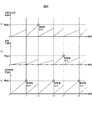
図5は、積算値の変化と制限値出力タイミングとの関係の一例を示す図である。図5において、(a)は充放電電流の積算値の変化の様子を、(b)は温度の積算値の変化の様子を、(c)は使用時間の変化の様子をそれぞれ表している。
バッテリコントローラ107が充放電制御を開始すると、(a)、(b)、(c)にそれぞれ示すように、充放電電流、温度、使用時間の各積算値がそれぞれ上昇していく。その結果、(c)に示すように、時刻t1において使用時間の積算値が閾値Cに達したとする。このとき、バッテリコントローラ107から上位コントローラ112に制限値が出力されると共に、各積算値がそれぞれ0にリセットされる。
時刻t1以降では、充放電電流、温度、使用時間の各積算値が再び上昇していく。その結果、今度は(a)に示すように、時刻t2において充放電電流の積算値が閾値Aに達したとする。このとき、バッテリコントローラ107から上位コントローラ112に制限値が出力されると共に、各積算値がそれぞれ0にリセットされる。
時刻t2以降でも、以上で説明したのと同様の処理が繰り返される。すなわち、(c)に示すように、時刻t3において使用時間の積算値が閾値Cに達すると、バッテリコントローラ107から上位コントローラ112に制限値が出力されると共に、各積算値がそれぞれ0にリセットされる。また、(b)に示すように、時刻t4において温度の積算値が閾値Bに達すると、バッテリコントローラ107から上位コントローラ112に制限値が出力されると共に、各積算値がそれぞれ0にリセットされる。さらに、(c)に示すように、時刻t5において使用時間の積算値が閾値Cに達すると、バッテリコントローラ107から上位コントローラ112に制限値が出力されると共に、各積算値がそれぞれ0にリセットされる。それ以降でも同様に、いずれかの積算値が閾値に達するごとに、バッテリコントローラ107から上位コントローラ112に制限値が出力され、各積算値がそれぞれ0にリセットされる。
なお、上記の例では、充放電電流、温度、使用時間の各積算値を例として説明したが、他の電池モジュール101の情報についても同様である。すなわち、タイミング判定部204は、電池情報取得部201により取得された電池モジュール101の複数の情報について積算値をそれぞれ算出し、各積算値をそれぞれの閾値と比較する。その結果、いずれか少なくとも一つの情報について積算値が閾値を超えたときに、制限値を出力すべきタイミングと判定することができる。
以上説明した本発明の一実施形態によれば、以下の作用効果を奏する。
(1)バッテリコントローラ107は、電池情報取得部201、劣化進行速度演算部202、制限値設定部203、タイミング判定部204および制限値出力部205を備える。電池情報取得部201は、蓄電池である電池モジュール101の情報を取得する(ステップS101)。劣化進行速度演算部202は、電池情報取得部201により取得された情報に基づいて、電池モジュール101の劣化進行速度を演算する(ステップS102)。制限値設定部203は、劣化進行速度演算部202により演算された劣化進行速度に基づいて、電池モジュール101の充放電を制御するための制限値を設定する(ステップS103)。タイミング判定部204は、電池情報取得部201により取得された情報に基づいて、制限値を出力すべきタイミングを判定する(ステップS104、105)。制限値出力部205は、タイミング判定部204により判定されたタイミングに基づいて、制限値を出力する(ステップS106)。このようにしたので、電池モジュール101の充放電制御を適切なタイミングで実施することができる。
(2)電池情報取得部201は、ステップS101において、電池モジュール101の充放電電流、電池モジュール101の温度、電池モジュール101の使用時間、電池モジュール101の充電状態のいずれか少なくとも一つの情報を取得することができる。さらに、電池情報取得部201は、ステップS101において、電池モジュール101が搭載されている車両の走行距離を電池モジュール101の情報として取得することもできる。このようにしたので、電池モジュール101の状態に関する様々な情報を取得することができる。
(3)タイミング判定部204は、ステップS105において、情報の積算値と所定の閾値とを比較し、積算値が閾値を超えたときに、制限値を出力すべきタイミングと判定する。このようにしたので、制限値を出力すべきタイミングを確実かつ容易に判定することができる。
(4)電池情報取得部201は、ステップS101において、電池モジュール101の複数の情報を取得することができる。この場合、タイミング判定部204は、ステップS104において、電池情報取得部201により取得された複数の情報の積算値をそれぞれ算出する。そして、ステップS105において、いずれか少なくとも一つの情報について積算値が閾値を超えたときに、制限値を出力すべきタイミングと判定する。このようにしたので、制限値を出力すべきタイミングの判定をより一層適切に行うことができる。
(第2の実施形態)
次に、本発明の第2の実施形態について説明する。本実施形態では、図1に示したバッテリコントローラ107において、前述の第1の実施形態とは異なる充放電制御を行う例を説明する。図6は、本発明の第2の実施形態に係るバッテリコントローラ107の機能ブロック図である。図6に示すように、本実施形態のバッテリコントローラ107は、図2の制限値設定部203、タイミング判定部204および制限値出力部205に替えて、制限値演算部206、制限値修正許可部207および制限値修正部208の各機能ブロックにより構成される。バッテリコントローラ107は、たとえばCPUにより所定のプログラムを実行することで、これらの機能ブロックを実現することができる。
次に、本発明の第2の実施形態について説明する。本実施形態では、図1に示したバッテリコントローラ107において、前述の第1の実施形態とは異なる充放電制御を行う例を説明する。図6は、本発明の第2の実施形態に係るバッテリコントローラ107の機能ブロック図である。図6に示すように、本実施形態のバッテリコントローラ107は、図2の制限値設定部203、タイミング判定部204および制限値出力部205に替えて、制限値演算部206、制限値修正許可部207および制限値修正部208の各機能ブロックにより構成される。バッテリコントローラ107は、たとえばCPUにより所定のプログラムを実行することで、これらの機能ブロックを実現することができる。
制限値演算部206は、劣化進行速度演算部202により演算された劣化進行速度に基づいて、電池モジュール101の充放電を制御するための制限値を演算する。制限値演算部206は、制限値設定部203が制限値を設定するのと同様の方法により、制限値を演算することができる。
制限値修正許可部207は、電池情報取得部201により電池モジュール101の情報として取得された電流、温度、SOC、走行距離、使用時間等の各情報に基づいて、現在設定されている制限値の修正を許可するか否かを判定する。なお、制限値修正許可部207による具体的な判定方法については、後で説明する。
制限値修正部208は、制限値修正許可部207により制限値の修正が許可されると、制限値演算部206により求められた制限値に基づいて、電池モジュール101の充放電制御に用いられる制限値を修正する。具体的には、制限値修正部208は、制限値演算部206により求められた最新の制限値が現在の充放電制御で設定されている制限値と異なっており、かつ制限値修正許可部207により制限値の修正が許可されたときに、制限値の修正を行う。そして、修正後の制限値を上位コントローラ112に出力する。制限値修正部208により制限値が修正されると、上位コントローラ112は、その修正後の制限値に従って電池システム100およびインバータ110を制御し、電池モジュール101の充放電制御を行う。なお、制限値修正許可部207により制限値の修正が許可されていない場合や、制限値演算部206により求められた制限値に変更がない場合には、制限値修正部208は、これまでの充放電制御で用いられていた制限値を修正せずに、そのまま上位コントローラ112に出力する。これらの場合、上位コントローラ112は、従来の制限値による電池モジュール101の充放電制御を継続して行う。
図7は、本発明の第2の実施形態に係る制限値修正許可部207の機能ブロック図である。図7に示すように、制限値修正許可部207は、電池使用状態推定部301および修正許可判定部302の各機能ブロックにより構成される。
電池使用状態推定部301は、電池情報取得部201から、電池モジュール101の電流、温度、SOC、使用時間や、電池モジュール101を搭載した車両の走行距離などの情報を取得する。そして、これらの情報に基づいて、電池モジュール101の使用状態を推定する。
修正許可判定部302は、電池使用状態推定部301により推定された電池モジュール101の使用状態と、電池モジュール101の使用時間とに基づいて、制限値の修正を許可するか否かを判定する。この判定結果は、制限値修正部208に出力される。
次に、電池使用状態推定部301において電池モジュール101の使用状態を推定する方法について説明する。図8は、充放電電流から電池使用状態を推定する方法を説明する図である。電池モジュール101の内部では、充放電に応じてリチウムイオンの移動が生じる。すなわち、充電時には、正極材料の表面や内部からリチウムイオンが脱離して電解液中を移動し、正極材料の表面に到達した後に材料内部へと拡散していく。放電時には、これと逆の現象が起きる。こうして移動するリチウムイオンの数は、充放電電流が大きくなるほど多くなる。また、リチウムイオンの移動に伴って電極材料が膨張、収縮を繰り返すため、充放電を繰り返すほど電極材料は機械的な負荷に晒される。すなわち、充放電電流の積算値は、電池モジュール101の劣化と相関がある。そのため、電池使用状態推定部301では、図8に示すように充放電電流の積算値を求めることで、充放電電流に関する電池モジュール101の使用状態を推定することができる。なお、充放電電流の値の符号が電流の流れる向きによって変化する場合には、充放電電流の絶対値を積算することで電池モジュール101の使用状態を推定することが好ましい。あるいは、充電電流と放電電流を分けてそれぞれ積算してもよい。
修正許可判定部302によって制限値の修正が許可されると、電池使用状態推定部301は、図8に示すように、それまでに積算された充放電電流の積算値をクリアし、0から再度積算を開始する。なお、積算値をクリアせずにそのまま充放電電流の積算を続けてもよい。
図9および図10は、温度から電池使用状態を推定する方法を説明する図である。一般的に、電池モジュール101のようなリチウムイオン二次電池では、高温や低温で使用されると劣化が促進されることが知られている。劣化が促進される具体的な温度条件は、電池モジュール101に使用される材料によって変動する。そのため、電池使用状態推定部301は、図9のような事前に把握された電池温度と劣化促進の関係に基づいて、電池モジュール101の劣化が促進される温度領域を定量的に決定し、電池モジュール101の劣化傾向を示す劣化傾向指数を求める。図9に示す例では、電池温度が低温または高温になるほど、電池モジュール101の劣化傾向指数が指数関数的に増大している。
電池使用状態推定部301では、図10に示すように電池温度に基づく劣化傾向指数の積算値を求めることで、温度に関する電池モジュール101の使用状態を推定することができる。なお、上記の説明では、電池温度と劣化促進の関係が指数関数的である場合の例を説明したが、温度に関する電池モジュール101の使用状態の推定方法はこれに限定されるものではない。ここでは、既知の電池温度と劣化傾向の関係に基づいて、温度に関する電池モジュール101の使用状態を推定できることが重要である。
修正許可判定部302によって制限値の修正が許可されると、電池使用状態推定部301は、図10に示すように、それまでに積算された劣化傾向指数の積算値をクリアし、0から再度積算を開始する。なお、積算値をクリアせずにそのまま劣化傾向指数の積算を続けてもよい。
図11および図12は、SOCから電池使用状態を推定する方法を説明する図である。一般的に、電池モジュール101のようなリチウムイオン二次電池では、SOCが高い領域や低い領域で使用されると劣化が促進されることが知られている。劣化が促進される具体的なSOC領域は、電池モジュール101に使用される材料によって変動する。そのため、電池使用状態推定部301は、図11のような事前に把握されたSOCと劣化促進の関係に基づいて、電池モジュール101の劣化が促進されるSOC領域を定量的に決定し、電池モジュール101の劣化傾向を示す劣化傾向指数を求める。図11に示す例では、低SOC領域または高SOC領域になるほど、電池モジュール101の劣化傾向指数が指数関数的に増大している。
電池使用状態推定部301では、図12に示すようにSOCに基づく劣化傾向指数の積算値を求めることで、SOCに関する電池モジュール101の使用状態を推定することができる。なお、上記の説明では、SOCと劣化促進の関係が指数関数的である場合の例を説明したが、SOCに関する電池モジュール101の使用状態の推定方法はこれに限定されるものではない。ここでも前述の温度の場合と同様に、既知のSOCと劣化傾向の関係に基づいて、SOCに関する電池モジュール101の使用状態を推定できることが重要である。
修正許可判定部302によって制限値の修正が許可されると、電池使用状態推定部301は、図12に示すように、それまでに積算された劣化傾向指数の積算値をクリアし、0から再度積算を開始する。なお、積算値をクリアせずにそのまま劣化傾向指数の積算を続けてもよい。
次に、電池使用状態推定部301により推定された電池モジュール101の使用状態に基づいて、修正許可判定部302において制限値の修正許可判定を行う方法について説明する。図13は、電池使用状態と制限値の修正許可判定結果との関係の一例を示す図である。図13では、前述の充放電電流に関する電池使用状態およびSOCに関する電池使用状態と、電池モジュール101の使用時間とに基づいて、制限値の修正許可判定を行う場合を示している。なお、具体的な説明は省略するが、他の使用状態を用いた場合にも同様である。
修正許可判定部302は、前回の制限値の変更から電池モジュール101の使用が進み、その効果が電池モジュール101の劣化状態の変化に反映されたと判断される場合に、制限値の修正を許可する。具体的には、図13に示すように、修正許可判定部302は、充放電電流に関する電池使用状態として、充放電電流を積算すると共に、SOCに関する電池使用状態として、SOCに基づく劣化傾向指数を積算する。また同時に、電池使用時間として、電池モジュール101の使用時間を積算する。そして、充放電電流に関する電池使用状態またはSOCに関する電池使用状態のいずれか少なくとも一方が、各々に対して予め設定された所定の許可判定閾値を超え、かつ電池使用時間が所定の許可判定閾値を超えたときに、修正許可判定が成立したと判断し、所定の修正許可信号を出力する。修正許可信号を出力したら、修正許可判定部302は、各積算値を0にリセットして再度積算を開始する。
図13の例では、電池使用時間が閾値を超えた後の時刻t11において、充放電電流に関する電池使用状態が閾値を超えることで、修正許可判定部302において修正許可判定の成立が判断され、修正許可信号が出力される。またその後、電池使用時間が閾値を超えた後の時刻t12において、SOCに関する電池使用状態が閾値を超えることで、修正許可判定部302において修正許可判定の成立が判断され、修正許可信号が出力される。さらにその後、充放電電流に関する電池使用状態が閾値を超えた後の時刻t13において、電池使用時間が閾値を超えることで、修正許可判定部302において修正許可判定の成立が判断され、修正許可信号が出力される。すなわちこの場合には、充放電電流に関する電池使用状態の値が閾値を超えてから電池使用時間が閾値を超えるまでの間は、前回の制限値の修正から十分な時間が経過していないとして、修正許可判定が成立しない。その後、電池使用時間が閾値に到達したときに、修正許可判定が成立する。
なお、時刻t14では、充放電電流に関する電池使用状態とSOCに関する電池使用状態のいずれもが閾値を超えていないが、電池使用時間が強制許可閾値を超えることで、修正許可判定部302において修正許可判定の成立が判断され、修正許可信号が出力される。この強制許可閾値は、前述の許可判定閾値よりも高い値で設定されている。これにより、修正許可判定部302は、電池モジュール101を搭載した車両が長期間放置される等の理由から、電池モジュール101の使用頻度が減少したときには、制限値の修正を許可する。すなわち、電池モジュール101の使用頻度が少ない場合には、充放電電流、温度、SOC、走行距離などの電池使用状態が増加していなくても、時間の経過によって電池モジュール101の経時劣化が進むことが懸念される。これを考慮して、修正許可判定部302は、電池使用時間が強制許可閾値を超えたときには、電池使用状態に関わらず、制限値の修正を許可する。
図14は、本発明の第2の実施形態に係るバッテリコントローラ107による電池モジュール101の充放電制御のフローチャートである。本実施形態のバッテリコントローラ107は、図14のフローチャートに従って、所定の処理周期ごとに電池モジュール101の充放電制御を実行する。
ステップS1001~S1003において、バッテリコントローラ107は、図3のステップS101~S103とそれぞれ同様の処理を実行する。
ステップS1004において、バッテリコントローラ107は、電池使用状態推定部301により、ステップS1001で取得した電池モジュール101の情報に基づいて、電池モジュール101の使用状態を推定する。ここでは、図8~図12で説明したような方法で、充放電電流、温度、SOC等に関する電池モジュール101の使用状態をそれぞれ推定する。
ステップS1005において、バッテリコントローラ107は、電池使用状態推定部301により、前回の制限値修正からの電池使用時間を算出する。
ステップS1006において、バッテリコントローラ107は、修正許可判定部302により、ステップS1004で推定した電池使用状態が許可判定閾値を超えているか否かを判定する。その結果、充放電電流、温度、SOC等に関する電池モジュール101の使用状態のうち、いずれか少なくとも一つの電池使用状態が許可判定閾値以上であれば、処理をステップS1007に進める。一方、いずれの電池使用状態も許可判定閾値未満であれば、処理をステップS1008に進める。
ステップS1007において、バッテリコントローラ107は、修正許可判定部302により、ステップS1005で算出した電池使用時間が許可判定閾値を超えているか否かを判定する。その結果、電池使用時間が許可判定閾値以上であれば、処理をステップS1009に進める。一方、電池使用時間が許可判定閾値未満であれば、処理をステップS1001に戻し、ステップS1001以降の処理を繰り返す。この場合、制限値の修正は行われない。
ステップS1008において、バッテリコントローラ107は、修正許可判定部302により、ステップS1005で算出した電池使用時間が強制許可閾値を超えているか否かを判定する。その結果、電池使用時間が強制許可閾値以上であれば、処理をステップS1009に進める。一方、電池使用時間が強制許可閾値未満であれば、処理をステップS1001に戻し、ステップS1001以降の処理を繰り返す。この場合にも、制限値の修正は行われない。
ステップS1009において、バッテリコントローラ107は、制限値修正部208により、ステップS103で設定した制限値に基づいて、電池モジュール101の充放電制御に用いられる制限値を修正する。そして、修正後の制限値を上位コントローラ112に出力する。
ステップS1010において、バッテリコントローラ107は、電池使用状態推定部301により、ステップS1004で推定した電池使用状態と、ステップS1005で算出した電池使用時間とを、それぞれ0にリセットする。ステップS1010を実行したら、バッテリコントローラ107は、図14のフローチャートに示す処理を終了する。
以上説明した本発明の第2の実施形態によれば、以下の作用効果を奏する。
(1)バッテリコントローラ107は、電池情報取得部201、劣化進行速度演算部202、制限値演算部206、電池使用状態推定部301、修正許可判定部302および制限値修正部208を備える。電池情報取得部201は、蓄電池である電池モジュール101の情報を取得する(ステップS1001)。劣化進行速度演算部202は、電池情報取得部201により取得された情報に基づいて、電池モジュール101の劣化進行速度を演算する(ステップS1002)。制限値演算部206は、劣化進行速度演算部202により演算された劣化進行速度に基づいて、電池モジュール101の充放電を制御するための制限値を演算する(ステップS1003)。電池使用状態推定部301は、電池情報取得部201により取得された情報に基づいて、電池モジュール101の使用状態を推定する(ステップS1004)。修正許可判定部302は、電池使用状態推定部301により推定された電池モジュール101の使用状態と、電池モジュール101の使用時間とに基づいて、制限値の修正を許可するか否かを判定する(ステップS1006~S1008)。制限値修正部208は、制限値演算部206により求められた制限値と、修正許可判定部302による判定結果とに基づいて、設定されている制限値を修正する(ステップS1009)。このようにしたので、第1の実施形態と同様に、電池モジュール101の充放電制御を適切なタイミングで実施することができる。
(2)電池情報取得部201は、ステップS1001において、電池モジュール101の充放電電流、電池モジュール101の温度、電池モジュール101の充電状態のいずれか少なくとも一つの情報を取得する。電池使用状態推定部301は、ステップS1004において、充放電電流に関する電池モジュール101の使用状態、温度に関する電池モジュール101の使用状態、充電状態に関する電池モジュール101の使用状態のいずれか少なくとも一つを推定する。修正許可判定部302は、充放電電流に関する電池モジュール101の使用状態、温度に関する電池モジュール101の使用状態、充電状態に関する電池モジュール101の使用状態のいずれか少なくとも一つの推定値が、各々に対して予め定められた所定の閾値よりも大きいとステップS1006で判定し、かつ、電池モジュール101の使用時間が所定の許可判定時間以上であるとステップS1007で判定した場合に、ステップS1009において制限値の修正を許可する。このようにしたので、適切なタイミングで制限値の修正を許可することができる。
(3)修正許可判定部302は、電池モジュール101の使用時間が所定の強制許可時間以上であるとステップS1008で判定した場合に、電池モジュール101の使用状態に関わらず、ステップS1009において制限値の修正を許可する。このようにしたので、電池モジュール101の使用状態の変化が小さくても、時間の経過によって電池モジュール101の経時劣化が進むことが懸念されるときに、適切なタイミングで制限値の修正を許可することができる。
なお、本発明は上記の実施形態に限定されるものではない。本発明の技術的思想の範囲内で考えられるその他の態様も本発明の範囲内に含まれる。
100:電池システム
101:電池モジュール
102:電流センサ
103:電圧センサ
104:温度センサ
105:漏電センサ
106A,106B:リレー
107:バッテリコントローラ
110:インバータ
111:負荷
112:上位コントローラ
201:電池情報取得部
202:劣化進行速度演算部
203:制限値設定部
204:タイミング判定部
205:制限値出力部
206:制限値演算部
207:制限値修正許可部
208:制限値修正部
301:電池使用状態推定部
302:修正許可判定部
101:電池モジュール
102:電流センサ
103:電圧センサ
104:温度センサ
105:漏電センサ
106A,106B:リレー
107:バッテリコントローラ
110:インバータ
111:負荷
112:上位コントローラ
201:電池情報取得部
202:劣化進行速度演算部
203:制限値設定部
204:タイミング判定部
205:制限値出力部
206:制限値演算部
207:制限値修正許可部
208:制限値修正部
301:電池使用状態推定部
302:修正許可判定部
Claims (8)
- 蓄電池の情報を取得する電池情報取得部と、
前記電池情報取得部により取得された前記情報に基づいて、前記蓄電池の劣化進行速度を演算する劣化進行速度演算部と、
前記劣化進行速度演算部により演算された前記劣化進行速度に基づいて、前記蓄電池の充放電を制御するための制限値を設定する制限値設定部と、
前記電池情報取得部により取得された前記情報に基づいて、前記制限値を出力すべきタイミングを判定するタイミング判定部と、
前記タイミング判定部により判定された前記タイミングに基づいて、前記制限値を出力する制限値出力部と、を備える蓄電池制御装置。 - 請求項1に記載の蓄電池制御装置において、
前記電池情報取得部は、前記蓄電池の充放電電流、前記蓄電池の温度、前記蓄電池の使用時間、前記蓄電池の充電状態のいずれか少なくとも一つの情報を取得する蓄電池制御装置。 - 請求項2に記載の蓄電池制御装置において、
前記蓄電池は、車両に搭載されており、
前記電池情報取得部は、前記車両の走行距離を前記蓄電池の情報として取得する蓄電池制御装置。 - 請求項2または3に記載の蓄電池制御装置において、
前記タイミング判定部は、前記情報の積算値と所定の閾値とを比較し、前記積算値が前記閾値を超えたときに、前記制限値を出力すべきタイミングと判定する蓄電池制御装置。 - 請求項4に記載の蓄電池制御装置において、
前記電池情報取得部は、前記蓄電池の複数の情報を取得し、
前記タイミング判定部は、前記電池情報取得部により取得された前記複数の情報の積算値をそれぞれ算出し、いずれか少なくとも一つの情報について前記積算値が前記閾値を超えたときに、前記制限値を出力すべきタイミングと判定する蓄電池制御装置。 - 蓄電池の情報を取得する電池情報取得部と、
前記電池情報取得部により取得された前記情報に基づいて、前記蓄電池の劣化進行速度を演算する劣化進行速度演算部と、
前記劣化進行速度演算部により演算された前記劣化進行速度に基づいて、前記蓄電池の充放電を制御するための制限値を演算する制限値演算部と、
前記電池情報取得部により取得された前記情報に基づいて、前記蓄電池の使用状態を推定する電池使用状態推定部と、
前記電池使用状態推定部により推定された前記蓄電池の使用状態と、前記蓄電池の使用時間とに基づいて、前記制限値の修正を許可するか否かを判定する修正許可判定部と、
前記制限値演算部により求められた前記制限値と、前記修正許可判定部による判定結果とに基づいて、設定されている前記制限値を修正する制限値修正部と、を備える蓄電池制御装置。 - 請求項6に記載の蓄電池制御装置において、
前記電池情報取得部は、前記蓄電池の充放電電流、前記蓄電池の温度、前記蓄電池の充電状態のいずれか少なくとも一つの情報を取得し、
前記電池使用状態推定部は、前記充放電電流に関する前記蓄電池の使用状態、前記温度に関する前記蓄電池の使用状態、前記充電状態に関する前記蓄電池の使用状態のいずれか少なくとも一つを推定し、
前記修正許可判定部は、前記充放電電流に関する前記蓄電池の使用状態、前記温度に関する前記蓄電池の使用状態、前記充電状態に関する前記蓄電池の使用状態のいずれか少なくとも一つの推定値が、各々に対して予め定められた所定の閾値よりも大きく、かつ前記蓄電池の使用時間が所定の許可判定時間以上である場合に、前記制限値の修正を許可する蓄電池制御装置。 - 請求項7に記載の蓄電池制御装置において、
前記修正許可判定部は、前記蓄電池の使用時間が所定の強制許可時間以上である場合に、前記蓄電池の使用状態に関わらず、前記制限値の修正を許可する蓄電池制御装置。
Priority Applications (3)
| Application Number | Priority Date | Filing Date | Title |
|---|---|---|---|
| CN201680037242.5A CN108028438B (zh) | 2015-09-09 | 2016-08-08 | 蓄电池控制装置 |
| US15/738,281 US11226376B2 (en) | 2015-09-09 | 2016-08-08 | Storage battery control device |
| EP16844103.8A EP3352289B1 (en) | 2015-09-09 | 2016-08-08 | Storage battery control device |
Applications Claiming Priority (2)
| Application Number | Priority Date | Filing Date | Title |
|---|---|---|---|
| JP2015-177560 | 2015-09-09 | ||
| JP2015177560A JP6467320B2 (ja) | 2015-09-09 | 2015-09-09 | 蓄電池制御装置 |
Publications (1)
| Publication Number | Publication Date |
|---|---|
| WO2017043239A1 true WO2017043239A1 (ja) | 2017-03-16 |
Family
ID=58239381
Family Applications (1)
| Application Number | Title | Priority Date | Filing Date |
|---|---|---|---|
| PCT/JP2016/073226 Ceased WO2017043239A1 (ja) | 2015-09-09 | 2016-08-08 | 蓄電池制御装置 |
Country Status (5)
| Country | Link |
|---|---|
| US (1) | US11226376B2 (ja) |
| EP (1) | EP3352289B1 (ja) |
| JP (1) | JP6467320B2 (ja) |
| CN (1) | CN108028438B (ja) |
| WO (1) | WO2017043239A1 (ja) |
Cited By (2)
| Publication number | Priority date | Publication date | Assignee | Title |
|---|---|---|---|---|
| JP2019041481A (ja) * | 2017-08-24 | 2019-03-14 | 本田技研工業株式会社 | 充放電管理装置 |
| WO2020026502A1 (ja) | 2018-07-30 | 2020-02-06 | 日立オートモティブシステムズ株式会社 | 電池管理装置、電池管理方法、電力貯蔵システム |
Families Citing this family (78)
| Publication number | Priority date | Publication date | Assignee | Title |
|---|---|---|---|---|
| US10226376B2 (en) | 2014-03-19 | 2019-03-12 | Purewick Corporation | Apparatus and methods for receiving discharged urine |
| US11376152B2 (en) | 2014-03-19 | 2022-07-05 | Purewick Corporation | Apparatus and methods for receiving discharged urine |
| US10952889B2 (en) | 2016-06-02 | 2021-03-23 | Purewick Corporation | Using wicking material to collect liquid for transport |
| US10390989B2 (en) | 2014-03-19 | 2019-08-27 | Purewick Corporation | Apparatus and methods for receiving discharged urine |
| US11806266B2 (en) | 2014-03-19 | 2023-11-07 | Purewick Corporation | Apparatus and methods for receiving discharged urine |
| US10376406B2 (en) | 2016-07-27 | 2019-08-13 | Purewick Corporation | Male urine collection device using wicking material |
| US10973678B2 (en) | 2016-07-27 | 2021-04-13 | Purewick Corporation | Apparatus and methods for receiving discharged urine |
| JP2018046667A (ja) * | 2016-09-14 | 2018-03-22 | 株式会社東芝 | 充電パターン作成装置、充電制御装置、充電パターン作成方法、プログラム、及び蓄電システム |
| KR102035678B1 (ko) * | 2016-11-01 | 2019-10-23 | 주식회사 엘지화학 | 배터리 노화상태 산출 방법 및 장치 |
| FR3060889B1 (fr) * | 2016-12-21 | 2020-12-04 | Commissariat Energie Atomique | Procede et dispositif de charge d'une batterie |
| WO2018144463A1 (en) | 2017-01-31 | 2018-08-09 | Purewick Corporation | Apparatus and methods for receiving discharged urine |
| JP7103809B2 (ja) * | 2018-03-22 | 2022-07-20 | ビークルエナジージャパン株式会社 | 電池制御装置 |
| JP7001519B2 (ja) * | 2018-03-27 | 2022-02-03 | ビークルエナジージャパン株式会社 | 電池管理装置、電池管理方法、電力貯蔵システム |
| JP7072084B2 (ja) | 2018-05-01 | 2022-05-19 | ピュアウィック コーポレイション | 流体収集装置、関連システム、及び関連方法 |
| AU2019262945B2 (en) | 2018-05-01 | 2022-08-25 | Purewick Corporation | Fluid collection devices and methods of using the same |
| US11944740B2 (en) | 2018-05-01 | 2024-04-02 | Purewick Corporation | Fluid collection devices, related systems, and related methods |
| EP3787571B1 (en) | 2018-05-01 | 2022-06-01 | Purewick Corporation | Fluid collection garments |
| EP3787569B1 (en) | 2018-05-01 | 2025-07-16 | Purewick Corporation | Fluid collection devices and systems |
| AU2019262939A1 (en) | 2018-05-01 | 2020-11-26 | Purewick Corporation | Fluid collection devices, systems, and methods |
| CN109334508B (zh) * | 2018-09-26 | 2020-09-29 | 潍柴动力股份有限公司 | 动力电池充放电保护方法及装置 |
| JP7259282B2 (ja) * | 2018-11-21 | 2023-04-18 | トヨタ自動車株式会社 | 電池の劣化認証装置および電池の劣化認証システム |
| JP7244746B2 (ja) * | 2019-02-22 | 2023-03-23 | ミツミ電機株式会社 | 電子機器及びその状態判定方法 |
| KR102493232B1 (ko) | 2019-03-18 | 2023-01-27 | 주식회사 엘지에너지솔루션 | 배터리 관리 장치 |
| KR102521576B1 (ko) * | 2019-03-18 | 2023-04-12 | 주식회사 엘지에너지솔루션 | 배터리 관리 장치 |
| US12296714B2 (en) * | 2019-06-12 | 2025-05-13 | Mitsubishi Electric Corporation | Charge and discharge control device and charge and discharge control method including first, second, and third charge level ranges |
| JP7271328B2 (ja) * | 2019-06-13 | 2023-05-11 | 本田技研工業株式会社 | 制御装置、制御方法、及びプログラム |
| CA3143904C (en) | 2019-06-21 | 2023-11-28 | Purewick Corporation | Fluid collection devices including a base securement area, and related systems and methods |
| ES2961269T3 (es) | 2019-07-11 | 2024-03-11 | Purewick Corp | Dispositivos y sistemas de recogida de líquido |
| WO2021016026A1 (en) | 2019-07-19 | 2021-01-28 | Purewick Corporation | Fluid collection devices including at least one shape memory material |
| JP7137767B2 (ja) * | 2019-09-25 | 2022-09-15 | トヨタ自動車株式会社 | 組電池送風システムおよび車両 |
| EP4051190B1 (en) | 2019-10-28 | 2024-05-22 | Purewick Corporation | Fluid collection assemblies including a sample port |
| JP7060561B2 (ja) * | 2019-11-08 | 2022-04-26 | 本田技研工業株式会社 | バッテリ状態判定システム、バッテリ状態判定方法、およびプログラム |
| EP4559443A3 (en) | 2020-01-03 | 2025-06-18 | Purewick Corporation | Urine collection devices having a relatively wide portion and an elongated portion and related methods |
| WO2021188817A1 (en) | 2020-03-19 | 2021-09-23 | Purewick Corporation | Fluid collection assemblies including one or more movement enhancing features |
| US12521288B2 (en) | 2020-03-26 | 2026-01-13 | Purewick Corporation | Multi-layer urine capture device and related methods |
| WO2021207621A1 (en) | 2020-04-10 | 2021-10-14 | Purewick Corporation | Fluid collection assemblies including one or more leak prevention features |
| US12465514B2 (en) | 2020-04-17 | 2025-11-11 | Purewick Corporation | Fluid collection devices, systems, and methods securing a protruding portion in position for use |
| WO2021211801A1 (en) | 2020-04-17 | 2021-10-21 | Purewick Corporation | Fluid collection assemblies including a fluid impermeable barrier having a sump and a base |
| US12472090B2 (en) | 2020-04-17 | 2025-11-18 | Purewick Corporation | Female external catheter devices having a urethral cup, and related systems and methods |
| US12491104B2 (en) | 2020-04-20 | 2025-12-09 | Purewick Corporation | Fluid collection devices adjustable between a vacuum-based orientation and a gravity-based orientation, and related systems and methods |
| US12048643B2 (en) | 2020-05-27 | 2024-07-30 | Purewick Corporation | Fluid collection assemblies including at least one inflation device and methods and systems of using the same |
| USD967409S1 (en) | 2020-07-15 | 2022-10-18 | Purewick Corporation | Urine collection apparatus cover |
| US12440371B2 (en) | 2020-08-06 | 2025-10-14 | Purewick Corporation | Fluid collection system including a garment and a fluid collection device |
| US12350187B2 (en) | 2020-08-11 | 2025-07-08 | Purewick Corporation | Fluid collection assemblies defining waist and leg openings |
| EP4210643A1 (en) | 2020-09-09 | 2023-07-19 | Purewick Corporation | Fluid collection devices, systems, and methods |
| US11801186B2 (en) | 2020-09-10 | 2023-10-31 | Purewick Corporation | Urine storage container handle and lid accessories |
| US12156792B2 (en) | 2020-09-10 | 2024-12-03 | Purewick Corporation | Fluid collection assemblies including at least one inflation device |
| US12042423B2 (en) | 2020-10-07 | 2024-07-23 | Purewick Corporation | Fluid collection systems including at least one tensioning element |
| US12257174B2 (en) | 2020-10-21 | 2025-03-25 | Purewick Corporation | Fluid collection assemblies including at least one of a protrusion or at least one expandable material |
| US12569365B2 (en) | 2020-10-21 | 2026-03-10 | Purewick Corporation | Fluid collection assemblies including at least one shape memory material disposed in the conduit |
| US12440370B2 (en) | 2020-10-21 | 2025-10-14 | Purewick Corporation | Apparatus with compressible casing for receiving discharged urine |
| US12208031B2 (en) | 2020-10-21 | 2025-01-28 | Purewick Corporation | Adapters for fluid collection devices |
| US12048644B2 (en) | 2020-11-03 | 2024-07-30 | Purewick Corporation | Apparatus for receiving discharged urine |
| US12070432B2 (en) | 2020-11-11 | 2024-08-27 | Purewick Corporation | Urine collection system including a flow meter and related methods |
| US12245967B2 (en) | 2020-11-18 | 2025-03-11 | Purewick Corporation | Fluid collection assemblies including an adjustable spine |
| US12599495B2 (en) | 2021-01-05 | 2026-04-14 | Purewick Corporation | Male external catheter with attachment interface configured to bias against penis |
| US12268627B2 (en) | 2021-01-06 | 2025-04-08 | Purewick Corporation | Fluid collection assemblies including at least one securement body |
| JP2024503636A (ja) | 2021-01-07 | 2024-01-26 | ピュアウィック コーポレイション | 車椅子に固定可能な尿収集システムおよび関連する方法 |
| EP4349306A3 (en) | 2021-01-19 | 2024-06-05 | Purewick Corporation | Variable fit fluid collection devices |
| US12178735B2 (en) | 2021-02-09 | 2024-12-31 | Purewick Corporation | Noise reduction for a urine suction system |
| EP4274524B1 (en) | 2021-02-26 | 2024-08-28 | Purewick Corporation | A male fluid collection device configured as a male urine collection device |
| US12551385B2 (en) | 2021-03-05 | 2026-02-17 | Purewick Corporation | Fluid collection assembly including a tube having porous wicking material for improved fluid transport |
| US12558472B2 (en) | 2021-03-05 | 2026-02-24 | Purewick Corporation | Portable fluid collection systems with storage and related methods |
| US12458525B2 (en) | 2021-03-10 | 2025-11-04 | Purewick Corporation | Acoustic silencer for a urine suction system |
| US12029677B2 (en) | 2021-04-06 | 2024-07-09 | Purewick Corporation | Fluid collection devices having a collection bag, and related systems and methods |
| EP4325688A4 (en) * | 2021-04-12 | 2025-03-12 | Murata Manufacturing Co., Ltd. | CHARACTERISTIC REUPGRADE METHOD AND CHARACTERISTIC UPGRADE DEVICE |
| US12233003B2 (en) | 2021-04-29 | 2025-02-25 | Purewick Corporation | Fluid collection assemblies including at least one length adjusting feature |
| US12251333B2 (en) | 2021-05-21 | 2025-03-18 | Purewick Corporation | Fluid collection assemblies including at least one inflation device and methods and systems of using the same |
| US12324767B2 (en) | 2021-05-24 | 2025-06-10 | Purewick Corporation | Fluid collection assembly including a customizable external support and related methods |
| US12150885B2 (en) | 2021-05-26 | 2024-11-26 | Purewick Corporation | Fluid collection system including a cleaning system and methods |
| US12575960B2 (en) | 2021-06-24 | 2026-03-17 | Purewick Corporation | Urine collection systems having one or more of volume, pressure, or flow indicators, and related methods |
| US12551366B2 (en) | 2021-08-02 | 2026-02-17 | Purewick Corporation | Fluid collection devices having multiple fluid collection regions, and related systems and methods |
| JP7399918B2 (ja) * | 2021-09-02 | 2023-12-18 | プライムプラネットエナジー&ソリューションズ株式会社 | 車載電池管理装置 |
| US12594062B2 (en) | 2021-09-08 | 2026-04-07 | Purewick Corporation | Fluid collection assemblies including an extension |
| JP7452508B2 (ja) * | 2021-09-28 | 2024-03-19 | トヨタ自動車株式会社 | バッテリー診断装置、方法、プログラム、及び車両 |
| CN114407727A (zh) * | 2022-01-24 | 2022-04-29 | 四川野马汽车股份有限公司 | 一种电动汽车充电剩余时间的估算方法及系统 |
| JP7499801B2 (ja) * | 2022-03-30 | 2024-06-14 | 本田技研工業株式会社 | 制御装置、移動体、方法及びプログラム |
| CN117465291B (zh) * | 2023-12-27 | 2024-04-02 | 中航锂电(洛阳)有限公司 | 一种估算磷酸铁锂电池混动车辆电量soc的方法及车辆 |
Citations (5)
| Publication number | Priority date | Publication date | Assignee | Title |
|---|---|---|---|---|
| JP2003297435A (ja) * | 2002-03-29 | 2003-10-17 | Honda Motor Co Ltd | 蓄電池の寿命予測装置および蓄電池の制御装置 |
| JP2008024124A (ja) * | 2006-07-20 | 2008-02-07 | Honda Motor Co Ltd | 車両用電源の制御装置およびその制御方法 |
| JP2013065481A (ja) * | 2011-09-20 | 2013-04-11 | Hitachi Ltd | リチウムイオン二次電池制御システムおよび組電池制御システム |
| JP2014003826A (ja) * | 2012-06-19 | 2014-01-09 | Toyota Motor Corp | 電池システムおよび制御方法 |
| WO2015001751A1 (ja) * | 2013-07-03 | 2015-01-08 | パナソニックIpマネジメント株式会社 | 車両用蓄電池管理装置、車両用電力装置、および車両用蓄電池の管理方法 |
Family Cites Families (13)
| Publication number | Priority date | Publication date | Assignee | Title |
|---|---|---|---|---|
| JP5220269B2 (ja) * | 2005-09-16 | 2013-06-26 | 古河電気工業株式会社 | 蓄電池の劣化状態・充電状態の検知方法及びその装置 |
| JP4952031B2 (ja) * | 2006-04-14 | 2012-06-13 | トヨタ自動車株式会社 | 電源装置および電源装置における入出力制限設定方法並びに車両およびその制御方法 |
| JP2007323999A (ja) | 2006-06-01 | 2007-12-13 | Fuji Heavy Ind Ltd | 自動車のバッテリ制御装置 |
| CN102648104B (zh) * | 2009-11-17 | 2015-04-22 | 丰田自动车株式会社 | 车辆及车辆的控制方法 |
| US8648603B2 (en) | 2010-04-21 | 2014-02-11 | Toyota Jidosha Kabushiki Kaisha | Deterioration degree calculating apparatus for secondary battery, vehicle equipped with the apparatus, and deterioration degree calculating method for secondary battery |
| JP5321757B2 (ja) * | 2011-01-27 | 2013-10-23 | トヨタ自動車株式会社 | 蓄電装置の制御装置および制御方法 |
| KR101605491B1 (ko) * | 2011-09-28 | 2016-03-22 | 도요타 지도샤(주) | 비수 이차 전지의 제어 장치 및 제어 방법 |
| JP5819443B2 (ja) * | 2011-12-22 | 2015-11-24 | 日立オートモティブシステムズ株式会社 | 電池制御装置、電池システム |
| JP5926950B2 (ja) * | 2011-12-22 | 2016-05-25 | 京セラ株式会社 | 電子機器 |
| JP5655838B2 (ja) * | 2012-10-25 | 2015-01-21 | トヨタ自動車株式会社 | 電池システム |
| JP6174963B2 (ja) * | 2013-09-30 | 2017-08-02 | 日立オートモティブシステムズ株式会社 | 電池制御システム |
| EP3085593A4 (en) * | 2013-12-17 | 2017-12-06 | Honda Motor Co., Ltd. | Vehicle |
| WO2015115044A1 (ja) * | 2014-01-29 | 2015-08-06 | パナソニックIpマネジメント株式会社 | 電池状態推定装置、及び電源装置 |
-
2015
- 2015-09-09 JP JP2015177560A patent/JP6467320B2/ja active Active
-
2016
- 2016-08-08 US US15/738,281 patent/US11226376B2/en active Active
- 2016-08-08 EP EP16844103.8A patent/EP3352289B1/en active Active
- 2016-08-08 WO PCT/JP2016/073226 patent/WO2017043239A1/ja not_active Ceased
- 2016-08-08 CN CN201680037242.5A patent/CN108028438B/zh active Active
Patent Citations (5)
| Publication number | Priority date | Publication date | Assignee | Title |
|---|---|---|---|---|
| JP2003297435A (ja) * | 2002-03-29 | 2003-10-17 | Honda Motor Co Ltd | 蓄電池の寿命予測装置および蓄電池の制御装置 |
| JP2008024124A (ja) * | 2006-07-20 | 2008-02-07 | Honda Motor Co Ltd | 車両用電源の制御装置およびその制御方法 |
| JP2013065481A (ja) * | 2011-09-20 | 2013-04-11 | Hitachi Ltd | リチウムイオン二次電池制御システムおよび組電池制御システム |
| JP2014003826A (ja) * | 2012-06-19 | 2014-01-09 | Toyota Motor Corp | 電池システムおよび制御方法 |
| WO2015001751A1 (ja) * | 2013-07-03 | 2015-01-08 | パナソニックIpマネジメント株式会社 | 車両用蓄電池管理装置、車両用電力装置、および車両用蓄電池の管理方法 |
Non-Patent Citations (1)
| Title |
|---|
| See also references of EP3352289A4 * |
Cited By (6)
| Publication number | Priority date | Publication date | Assignee | Title |
|---|---|---|---|---|
| JP2019041481A (ja) * | 2017-08-24 | 2019-03-14 | 本田技研工業株式会社 | 充放電管理装置 |
| US10913367B2 (en) | 2017-08-24 | 2021-02-09 | Honda Motor Co., Ltd. | Charge and discharge management device |
| WO2020026502A1 (ja) | 2018-07-30 | 2020-02-06 | 日立オートモティブシステムズ株式会社 | 電池管理装置、電池管理方法、電力貯蔵システム |
| JP2020022226A (ja) * | 2018-07-30 | 2020-02-06 | 日立オートモティブシステムズ株式会社 | 電池管理装置、電池管理方法、電力貯蔵システム |
| JP7185437B2 (ja) | 2018-07-30 | 2022-12-07 | ビークルエナジージャパン株式会社 | 電池管理装置、電池管理方法、電力貯蔵システム |
| US12283667B2 (en) | 2018-07-30 | 2025-04-22 | Vehicle Energy Japan Inc. | Battery management apparatus, battery management method, and battery energy storage system |
Also Published As
| Publication number | Publication date |
|---|---|
| JP2017054684A (ja) | 2017-03-16 |
| CN108028438B (zh) | 2022-05-10 |
| US11226376B2 (en) | 2022-01-18 |
| CN108028438A (zh) | 2018-05-11 |
| EP3352289B1 (en) | 2024-07-17 |
| JP6467320B2 (ja) | 2019-02-13 |
| EP3352289A4 (en) | 2020-01-22 |
| US20180210036A1 (en) | 2018-07-26 |
| EP3352289A1 (en) | 2018-07-25 |
Similar Documents
| Publication | Publication Date | Title |
|---|---|---|
| JP6467320B2 (ja) | 蓄電池制御装置 | |
| US10090686B2 (en) | Electrical storage system | |
| US9880224B2 (en) | Battery system monitoring device | |
| JP5708668B2 (ja) | 蓄電システム | |
| US9428177B2 (en) | Vehicle | |
| JP6160473B2 (ja) | 蓄電システム | |
| JP5623629B2 (ja) | 余寿命判定方法 | |
| JP5868499B2 (ja) | 電池制御装置 | |
| JP6500789B2 (ja) | 二次電池の制御システム | |
| WO2014147475A2 (en) | Electrical storage system, and full charge capacity estimation method for electrical storage device | |
| WO2016147572A1 (ja) | 電池管理装置、および電源装置 | |
| JP2009264962A (ja) | 二次電池の残存容量推定方法及び装置 | |
| JP6575308B2 (ja) | 内部抵抗算出装置、コンピュータプログラム及び内部抵抗算出方法 | |
| JP6214001B2 (ja) | 劣化要因推定方法及び余寿命推定方法 | |
| JP2018155706A (ja) | 二次電池の劣化状態推定装置並びにそれを備えた電池システム及び電動車両 | |
| JP6017790B2 (ja) | 蓄電システム | |
| JP6747333B2 (ja) | 二次電池システム | |
| JP5487183B2 (ja) | 蓄電装置の充電容量パラメータ推定装置 | |
| JP7006311B2 (ja) | 電動車両及び電動車両の制御方法 | |
| JP2015102344A (ja) | 推定装置 | |
| JP2017099092A (ja) | 電池制御装置 | |
| JP6225664B2 (ja) | 電池制御システム | |
| JP2017200313A (ja) | 組電池の充放電制御方法 | |
| JP2017195142A (ja) | 二次電池の塩濃度分布推定方法 |
Legal Events
| Date | Code | Title | Description |
|---|---|---|---|
| 121 | Ep: the epo has been informed by wipo that ep was designated in this application |
Ref document number: 16844103 Country of ref document: EP Kind code of ref document: A1 |
|
| WWE | Wipo information: entry into national phase |
Ref document number: 15738281 Country of ref document: US |
|
| NENP | Non-entry into the national phase |
Ref country code: DE |