WO2017047242A1 - ボイラ - Google Patents
ボイラ Download PDFInfo
- Publication number
- WO2017047242A1 WO2017047242A1 PCT/JP2016/072077 JP2016072077W WO2017047242A1 WO 2017047242 A1 WO2017047242 A1 WO 2017047242A1 JP 2016072077 W JP2016072077 W JP 2016072077W WO 2017047242 A1 WO2017047242 A1 WO 2017047242A1
- Authority
- WO
- WIPO (PCT)
- Prior art keywords
- flue
- exhaust gas
- closing
- closing device
- reducing agent
- Prior art date
- Legal status (The legal status is an assumption and is not a legal conclusion. Google has not performed a legal analysis and makes no representation as to the accuracy of the status listed.)
- Ceased
Links
Images




Classifications
-
- B—PERFORMING OPERATIONS; TRANSPORTING
- B01—PHYSICAL OR CHEMICAL PROCESSES OR APPARATUS IN GENERAL
- B01D—SEPARATION
- B01D53/00—Separation of gases or vapours; Recovering vapours of volatile solvents from gases; Chemical or biological purification of waste gases, e.g. engine exhaust gases, smoke, fumes, flue gases, aerosols
- B01D53/34—Chemical or biological purification of waste gases
- B01D53/74—General processes for purification of waste gases; Apparatus or devices specially adapted therefor
- B01D53/86—Catalytic processes
- B01D53/90—Injecting reactants
-
- B—PERFORMING OPERATIONS; TRANSPORTING
- B01—PHYSICAL OR CHEMICAL PROCESSES OR APPARATUS IN GENERAL
- B01D—SEPARATION
- B01D53/00—Separation of gases or vapours; Recovering vapours of volatile solvents from gases; Chemical or biological purification of waste gases, e.g. engine exhaust gases, smoke, fumes, flue gases, aerosols
- B01D53/34—Chemical or biological purification of waste gases
- B01D53/74—General processes for purification of waste gases; Apparatus or devices specially adapted therefor
- B01D53/86—Catalytic processes
- B01D53/8621—Removing nitrogen compounds
- B01D53/8625—Nitrogen oxides
- B01D53/8631—Processes characterised by a specific device
-
- F—MECHANICAL ENGINEERING; LIGHTING; HEATING; WEAPONS; BLASTING
- F23—COMBUSTION APPARATUS; COMBUSTION PROCESSES
- F23C—METHODS OR APPARATUS FOR COMBUSTION USING FLUID FUEL OR SOLID FUEL SUSPENDED IN A CARRIER GAS OR AIR
- F23C7/00—Combustion apparatus characterised by arrangements for air supply
- F23C7/008—Flow control devices
-
- F—MECHANICAL ENGINEERING; LIGHTING; HEATING; WEAPONS; BLASTING
- F23—COMBUSTION APPARATUS; COMBUSTION PROCESSES
- F23J—REMOVAL OR TREATMENT OF COMBUSTION PRODUCTS OR COMBUSTION RESIDUES; FLUES
- F23J15/00—Arrangements of devices for treating smoke or fumes
-
- F—MECHANICAL ENGINEERING; LIGHTING; HEATING; WEAPONS; BLASTING
- F23—COMBUSTION APPARATUS; COMBUSTION PROCESSES
- F23J—REMOVAL OR TREATMENT OF COMBUSTION PRODUCTS OR COMBUSTION RESIDUES; FLUES
- F23J15/00—Arrangements of devices for treating smoke or fumes
- F23J15/003—Arrangements of devices for treating smoke or fumes for supplying chemicals to fumes, e.g. using injection devices
-
- F—MECHANICAL ENGINEERING; LIGHTING; HEATING; WEAPONS; BLASTING
- F23—COMBUSTION APPARATUS; COMBUSTION PROCESSES
- F23J—REMOVAL OR TREATMENT OF COMBUSTION PRODUCTS OR COMBUSTION RESIDUES; FLUES
- F23J15/00—Arrangements of devices for treating smoke or fumes
- F23J15/08—Arrangements of devices for treating smoke or fumes of heaters
-
- B—PERFORMING OPERATIONS; TRANSPORTING
- B01—PHYSICAL OR CHEMICAL PROCESSES OR APPARATUS IN GENERAL
- B01D—SEPARATION
- B01D2251/00—Reactants
- B01D2251/20—Reductants
-
- B—PERFORMING OPERATIONS; TRANSPORTING
- B01—PHYSICAL OR CHEMICAL PROCESSES OR APPARATUS IN GENERAL
- B01D—SEPARATION
- B01D2258/00—Sources of waste gases
- B01D2258/02—Other waste gases
- B01D2258/0283—Flue gases
-
- F—MECHANICAL ENGINEERING; LIGHTING; HEATING; WEAPONS; BLASTING
- F22—STEAM GENERATION
- F22D—PREHEATING, OR ACCUMULATING PREHEATED, FEED-WATER FOR STEAM GENERATION; FEED-WATER SUPPLY FOR STEAM GENERATION; CONTROLLING WATER LEVEL FOR STEAM GENERATION; AUXILIARY DEVICES FOR PROMOTING WATER CIRCULATION WITHIN STEAM BOILERS
- F22D1/00—Feed-water heaters, i.e. economisers or like preheaters
- F22D1/36—Water and air preheating systems
-
- F—MECHANICAL ENGINEERING; LIGHTING; HEATING; WEAPONS; BLASTING
- F23—COMBUSTION APPARATUS; COMBUSTION PROCESSES
- F23J—REMOVAL OR TREATMENT OF COMBUSTION PRODUCTS OR COMBUSTION RESIDUES; FLUES
- F23J2215/00—Preventing emissions
- F23J2215/10—Nitrogen; Compounds thereof
-
- F—MECHANICAL ENGINEERING; LIGHTING; HEATING; WEAPONS; BLASTING
- F23—COMBUSTION APPARATUS; COMBUSTION PROCESSES
- F23J—REMOVAL OR TREATMENT OF COMBUSTION PRODUCTS OR COMBUSTION RESIDUES; FLUES
- F23J2215/00—Preventing emissions
- F23J2215/20—Sulfur; Compounds thereof
Definitions
- the present invention relates to a boiler for generating steam used for power generation or factory use.
- a conventional coal-fired boiler has a hollow furnace and is installed vertically in a furnace, and a plurality of combustion burners are disposed along the circumferential direction on the wall of the furnace.
- a flue is connected to the upper side of the furnace, and a heat exchanger for generating steam is disposed in the flue. Therefore, a flame is formed by the combustion burner injecting a mixture of fuel and air into the furnace, and a combustion gas is generated and flows to the flue. And the water which flows through a heat exchanger with the exhaust gas generated by combustion is heated, and steam is generated.
- an exhaust duct is connected to this flue, a denitration facility, an electrostatic precipitator, a desulfurization apparatus and the like are provided to the exhaust duct, and a chimney is provided at the downstream end.
- the denitrification equipment disposed in the exhaust duct supplies a reducing agent such as ammonia to the flue and promotes the reaction of the exhaust gas supplied with the reducing agent with nitrogen oxide and the reducing agent
- the nitrogen oxides in the exhaust gas are removed by passing the catalyst.
- the coal-fired boiler is provided with a bypass flow passage that bypasses the heat exchanger (carbon economizer), and by bypassing the high temperature exhaust gas to the upstream side of the NOx removal catalyst by the bypass flow passage during low load operation.
- the exhaust gas temperature is maintained above the reaction temperature.
- the high temperature exhaust gas When the high temperature exhaust gas is bypassed during the low load operation of the coal-fired boiler, the high temperature exhaust gas is mixed with the low temperature exhaust gas flowing through the flue.
- the temperature difference between the low temperature exhaust gas and the high temperature exhaust gas is large, there is a possibility that the acid ammonium sulfate may be precipitated in the low temperature exhaust gas to block the NOx removal catalyst because the temperature is not mixed sufficiently.
- the present invention is intended to solve the above-described problems, and has an object to provide a boiler that achieves low-temperature exhaust gas and high-temperature exhaust gas properly while achieving simplification of the structure and cost reduction.
- the boiler of the present invention is connected to a furnace having a hollow shape and installed along a vertical direction, a combustion device disposed in the furnace, and a vertically upper portion of the furnace. And a heat exchanger disposed in the flue, a reducing agent supply device disposed downstream of the heat exchanger in the flow direction of the exhaust gas in the flue, and A NOx removal catalyst disposed downstream of the reducing agent supply device in the flow direction of the exhaust gas, and one end thereof is connected to the upstream side of the flow direction of the exhaust gas from the heat exchanger in the flue, and the other end is the smoke
- a flow of exhaust gas from a downstream connection portion between a bypass flow path connected between the heat exchanger and the reducing agent supply device in a road and the flue to which the other end portion of the bypass flow path is connected Provided upstream in the direction A first closing device for closing a part of the flow path, and a second closing device provided on the upstream side of the downstream connection in the flue and closing a part of the
- the exhaust gas generated in the furnace flows into the flue and the exhaust heat is recovered by the heat exchanger, and then the reducing agent is supplied from the reducing agent supply device, and nitrogen oxides contained by the NOx removal catalyst Is removed.
- the flue is partially blocked by the second closing device, the exhaust gas flowing through the flue is rectified by pressure loss, and the flow velocity distribution is equalized.
- the exhaust gas generated in the furnace flows to the flue and the exhaust heat is recovered by the heat exchanger, and a part bypasses the heat exchanger by the bypass flow passage and returns to the flue
- the reducing agent is supplied from the reducing agent supply device, and the nitrogen oxides contained in the NOx removal catalyst are removed.
- the bypass flow passage a part of the flow passage is closed by the first closing device, so the exhaust gas flowing from the bypass flow passage to the flue has a penetration velocity maintained by the flow velocity rising, and the temperature distribution in the vertical direction is It is uniformed.
- the low temperature exhaust gas rectified by increasing the flow velocity by the second closing device is the first closing device.
- the penetration force of the high temperature exhaust gas flowing from the bypass flow path to the flue passage is not disturbed, and the low temperature exhaust gas and the high temperature exhaust gas are efficiently mixed by the turbulent flow.
- the structure can be simplified and the cost can be reduced, and the low temperature exhaust gas and the high temperature exhaust gas can be properly mixed.
- the flue is provided with a flue straight portion, and the second closing device and the reducing agent supply device are disposed in the flue straight portion.
- the second closing device and the reducing agent supply device in the straight part of the flue, the exhaust gas whose flow velocity distribution is equalized by the second closing device, or the temperature distribution by the first and second closing devices.
- the reducing agent is supplied to the homogenized exhaust gas, the variation of the reducing agent with respect to the exhaust gas becomes small, the reducing agent is uniformly supplied, and the nitrogen oxide removal efficiency by the NOx removal catalyst is improved. can do.
- the boiler according to the present invention is characterized in that the flow path adjustment damper is disposed on the upstream side of the second closing device in the flue straight portion.
- the reducing agent supply device can keep the exhaust gas whose flow velocity distribution and temperature distribution are equalized as it is. It is possible to improve the removal efficiency of nitrogen oxides by the NOx removal catalyst.
- the boiler according to the present invention is characterized in that a mixing space portion is provided on the downstream side of the first closing device in the flue and at a position facing the downstream connection portion.
- the mixing space portion on the downstream side of the first closing device and the second closing device, the high temperature exhaust gas flowing from the bypass flow path to the flue through the first closing device and the second closing device
- the low temperature exhaust gas is efficiently mixed in the mixing space, and the temperature distribution of the exhaust gas can be easily made uniform with a simple configuration.
- the first closing device and the second closing device are characterized in that they are disposed facing the mixing space portion.
- the high temperature exhaust gas and the low temperature exhaust gas are mixed by the mixing space in a state where the flow velocity is increased, and the temperature distribution of the exhaust gas can be easily made uniform.
- the second closing member is a closing plate along a direction orthogonal to the flow direction of the exhaust gas in the flue, and is characterized by being set to the same width along the vertical direction.
- the exhaust gas collides with the closing plate and swirls around the end of the closing plate, a swirl is generated, and the generated swirl can efficiently mix the high temperature exhaust gas and the low temperature exhaust gas.
- the closing plate is characterized in that a reinforcing plate extending to the downstream side in the flow direction of the exhaust gas is fixed.
- the closing plate is reinforced by the reinforcing plate and the rigidity is improved, the durability can be improved.
- the bypass passage is provided with the first closure device having the plurality of first closure members
- the flue is provided with the second closure device having the plurality of second closure members
- FIG. 1 is a schematic configuration diagram showing a coal-fired boiler of the present embodiment.
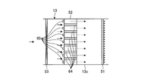
- FIG. 2 is a side view showing a flue of a coal-fired boiler.
- FIG. 3 is a plan view showing a flue of a coal-fired boiler.
- FIG. 4 is a perspective view showing a flue of a coal-fired boiler.
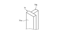
- FIG. 5 is a perspective view showing a modified example 1 of the second closing member.
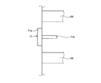
- FIG. 6 is a plan view showing the arrangement of the first modification of the second closing member.
- FIG. 7 is a perspective view showing a modification 2 of the second closing member.
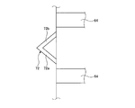
- FIG. 8 is a plan view showing the arrangement of a second modification of the second closing member.
- FIG. 1 is a schematic configuration diagram showing a coal-fired boiler of the present embodiment.
- the boiler according to the present embodiment uses pulverized coal obtained by pulverizing coal as pulverized fuel (solid fuel), burns the pulverized coal by a combustion burner, and is capable of recovering the heat generated by the combustion and using a pulverized coal burning boiler It is.
- the coal-fired boiler 10 is a conventional boiler, and includes a furnace 11, a combustion device 12 and a flue 13.
- the furnace 11 has a hollow shape of a square cylinder and is installed along the vertical direction, and the furnace wall constituting the furnace 11 is formed of a heat transfer pipe.
- the combustion device 12 is provided below the furnace wall (heat transfer pipe) that constitutes the furnace 11.
- the combustion apparatus 12 has a plurality of combustion burners 21, 22, 23, 24, 25 mounted on the furnace wall.
- four combustion burners 21, 22, 23, 24, 25 are disposed at equal intervals along the circumferential direction, and five sets along the vertical direction, that is, as one set. Five stages are arranged.
- the shape of the furnace, the number of combustion burners in one stage, and the number of stages are not limited to this embodiment.
- the respective combustion burners 21, 22, 23, 24, 25 are connected to pulverized coal machines (mills / mills) 31, 32, 33, 34, 35 via pulverized coal supply pipes 26, 27, 28, 29, 30. It is connected.
- the pulverized coal machine 31, 32, 33, 34, 35 is not shown, but the pulverizing table is rotatably supported within the housing with a rotational axis along the vertical direction, and a plurality of pulverized pieces are crushed above the pulverizing table The roller is rotatably supported in association with the rotation of the grinding table.
- the pulverized coal which has been pulverized to a predetermined size and classified by the transfer air is divided into pulverized coal feed pipes 26,
- the combustion burners 21, 22, 23, 24, 25 can be supplied from 27, 28, 29, 30.
- a wind box 36 is provided at the mounting position of each of the combustion burners 21, 22, 23, 24, 25 and one end of an air duct 37 is connected to the wind box 36.
- a blower 38 is mounted at the other end.
- the furnace 11 is provided with an additional air nozzle 39 above the mounting position of each of the combustion burners 21, 22, 23, 24, 25.
- a branch air duct 40 branched from the air duct 37 to the additional air nozzle 39. The ends of the are connected.
- the combustion air (fuel gas combustion air / secondary air) sent by the blower 38 is supplied from the air duct 37 to the air box 36, and the air box 36 supplies the combustion burners 21, 22, 23, 24,
- the combustion air (additional air) sent by the blower 38 can be supplied from the branch air duct 40 to the additional air nozzle 39 as well as being supplied to the H.25.
- the flue 13 is connected to the top of the furnace 11.
- the flue 13 is a heat exchanger for recovering the heat of the exhaust gas, and includes superheaters (superheaters) 41, 42, 43, reheaters (reheaters) 44, 45, and economizers 46, 47.
- the heat exchange is performed between the exhaust gas generated by the combustion in the furnace 11 and water.
- the flue 13 is connected to a gas duct 48 downstream of which the exhaust gas subjected to heat exchange is discharged.
- the gas duct 48 is provided with an air heater 49 between it and the air duct 37, and performs heat exchange between the air flowing through the air duct 37 and the exhaust gas flowing through the gas duct 48, and the combustion burners 21, 22, 23, 24, The combustion air supplied to 25 can be heated.
- the flue 13 is provided with a selective reduction catalyst (deNOx catalyst) 50 at a position upstream of the air heater 49.
- the selective reduction catalyst 50 supplies a reducing agent having the function of reducing nitrogen oxides such as ammonia and urea water into the flue 13, and the exhaust gas supplied with the reducing agent is reacted with the nitrogen oxide and the reducing agent.
- the flue 13 is provided with a reducing agent supply device 51 upstream of the selective reduction catalyst 50.
- the reducing agent supply device 51 can diffuse the reducing agent in the flow path through which the exhaust gas flows by supplying the reducing agent to the entire flow path in the flue 13 toward the downstream side.
- ammonia water, gaseous ammonia, urea water or the like can be used.
- the selective reduction catalyst 50 needs to maintain the temperature of the exhaust gas at a predetermined reaction temperature or higher in order to efficiently remove nitrogen oxides in the exhaust gas by the catalyst. Therefore, the flue 13 is provided with the bypass flow path 52 which bypasses the economizers 46 and 47 as a part of heat exchanger. One end of the bypass flow path 52 is connected between the reheater 45 and the economizer 46 in the flue 13, and the other end is connected upstream of the reducing agent supply device 51 in the flue 13.
- the flue 13 is provided with a flow adjustment damper 53 on the downstream side of the economizer 47, and the bypass flow passage 52 is provided with a flow adjustment damper 54.
- the opening degree of the flow rate adjustment damper 53 is reduced and the flow rate adjustment damper 54 is opened, whereby a part of the high temperature exhaust gas flowing through the flue 13 is bypassed.
- the economizers 46 and 47 are bypassed. Then, the temperature of the exhaust gas flowing through the flue 13 is reduced by heat recovery by the economizers 46 and 47, but since the high temperature exhaust gas passing through the bypass passage 52 is mixed, the exhaust gas temperature is selectively reduced It can be maintained above the reaction temperature of the mold catalyst 50.
- the gas duct 48 connected to the flue 13 is provided with a dust processing device (electric precipitator, desulfurizing device) 55 and an induction blower 56 at a position downstream of the air heater 49, and a chimney 57 at the downstream end.
- a dust processing device electric precipitator, desulfurizing device
- the pulverized coal machine 31, 32, 33, 34, 35 is driven, the pulverized coal produced together with the transfer air passes through the pulverized coal supply pipe 26, 27, 28, 29, 30 and the combustion burners 21, 22, 23, 23, 24 and 25 are supplied. Further, the heated combustion air is supplied from the air duct 37 to the combustion burners 21, 22, 23, 24, 25 via the air box 36. Then, the combustion burners 21, 22, 23, 24, 25 blow the pulverized fuel mixture of the pulverized coal and the conveying air into the furnace 11 and also the combustion air into the furnace 11 and ignite at this time. Can form a flame. In the furnace 11, the pulverized fuel mixture and the combustion air are burned to generate a flame, and when a flame is generated in the lower part in the furnace 11, the combustion gas (exhaust gas) ascends in the furnace 11 and the flue It is discharged to 13.
- the combustion gas exhaust gas
- the inside of the furnace 11 is maintained in a reducing atmosphere by setting the amount of supplied air to be less than the theoretical amount of air with respect to the supplied amount of pulverized coal. Then, the NOx generated by the combustion of the pulverized coal is reduced by the furnace 11, and after that, additional air is additionally supplied from the additional air nozzle 39, whereby the oxidation combustion of the pulverized coal is completed, and the generation of NOx by the combustion of the pulverized coal The amount is reduced.
- water supplied from a water supply pump (not shown) is preheated by economizers 46 and 47 and then supplied to a steam drum (not shown) and heated while being supplied to water pipes (not shown) of the furnace wall. It becomes saturated steam and is fed to a steam drum (not shown).
- saturated steam of a steam drum (not shown) is introduced into the superheaters 41, 42 and 43 and is overheated by the combustion gas.
- the superheated steam generated by the superheaters 41, 42, 43 is supplied to a power plant (for example, a turbine etc.) not shown.
- the steam taken out in the middle of the expansion process in the turbine is introduced into the reheaters 44 and 45, and is again overheated and returned to the turbine.
- the furnace 11 was demonstrated as a drum type (steam drum), it is not limited to this structure.
- the reducing agent is supplied from the reducing agent supply device 51 to the exhaust gas passing through the economizers 46 and 47 of the flue 13 and the exhaust gas passing through the bypass flow passage 52 and joining the exhaust gas of the flue 13. While flowing through 13, the complete material is diffused. Then, the exhaust gas of the flue 13 is subjected to reduction and removal of nitrogen oxides by the selective reduction type catalyst 50, and after the particulate matter is removed by the dust processing device 55 and the sulfur content is removed, Exhausted.
- FIG. 2 is a side view showing the flue of the coal-fired boiler
- FIG. 3 is a plan view showing the flue of the coal-fired boiler
- FIG. 4 is a perspective view showing the flue of the coal-fired boiler.
- the first closing device 61 for closing a part of the flow passage is provided upstream of the downstream connection portion with the flue 13 in the bypass flow passage 52, and the upstream side from the downstream connection portion in the flue 13
- a second closing device 62 is provided on the side for closing a part of the flow path.
- the exhaust gas mixing space 63 is provided at a position downstream of the first closing device 61 in the flue 13 and facing the second closing device 62.
- the closing ratio of the first closing device 61 and the second closing device 62 be 50% or less.
- the flue 13 includes a first horizontal flue portion 13a, a first vertical flue portion 13b, a second horizontal flue portion (a straight flue portion) 13c, a second vertical flue portion 13d, and a third horizontal flue.
- the portion 13e and the third vertical flue portion 13f are continuously provided.
- superheaters 41, 42, 43, reheaters 44, 45, economizers 46, 47 are disposed in the first horizontal flue portion 13a and the first vertical flue portion 13b.
- the flow rate adjustment damper 53 and the reducing agent supply device 51 are disposed in the second horizontal flue portion 13c, and the selective reduction catalyst 50 is disposed in the third vertical flue portion 13f.
- the reducing agent supply device 51 may be disposed in the second vertical flue portion 13d.
- the upstream connection portion 52a at one end side is connected between the reheater 45 and the economizer 46 in the first vertical flue portion 13b, and the downstream connection portion 52b at the other end is It is connected between the damper 53 for flow rate adjustment of the 2 horizontal flue part 13 c and the reducing agent supply device 51.
- the first closing device 61 is disposed to face the mixing space portion 63 of the flue 13 at the downstream connection portion 52b of the bypass passage 52, and the second closing device 62 is a second horizontal flue portion 13c.
- the mixing space portion 63 is disposed immediately upstream of the mixing space portion 63 in FIG.
- the first closing device 61 has a plurality of first closing members 64 provided along the flow direction of the exhaust gas in the flue 13 and at predetermined intervals in the width direction of the flue 13. ing.
- the second closing device 62 has a plurality of second closing members 65 provided along the vertical direction and at predetermined intervals in the width direction of the flue 13.
- the plurality of first closing members 64 and the plurality of second closing members 65 are disposed to be offset in the width direction of the flue 13.
- the flue 13 (second horizontal flue portion 13 c) is a flow passage having a rectangular cross-sectional shape in which the width in the horizontal direction is larger than the height in the vertical direction, and the bypass flow passage 52 is the flue 13.
- the flow path has a rectangular cross-sectional shape in which the horizontal width dimension in the horizontal direction perpendicular to the flow direction of the exhaust gas in the flue 13 is larger than the horizontal width dimension in the horizontal direction along the flow of the exhaust gas.
- the passage 52 has the same width dimension. That is, the bypass flow passage 52 is connected to be substantially orthogonal to the second horizontal flue portion 13c from above.
- the connection angle of the bypass flow passage 52 with respect to the second horizontal flue portion 13 c is not limited to 90 degrees, and may be inclined downstream or upstream of the flow of the exhaust gas in the flue 13.
- the plurality of first closing members 64 are disposed along the longitudinal width direction of the downstream connection portion 52b in the bypass flow passage 52, and are arranged with a predetermined gap in the lateral width direction.
- each first closing member 64 has a plate shape, and each end in the longitudinal direction is fixed to the inner wall surface of the bypass flow channel 52, and the downstream plane does not have a step with the inner wall surface of the flue 13. It is continuous.
- the plurality of second closing members 65 are disposed along the height direction of the portion immediately upstream of the downstream connection portion 52 b of the bypass flow passage 52 in the flue 13 and with a predetermined gap in the width direction.
- each second closing member 65 has a plate shape, each end in the longitudinal direction is fixed to the inner wall surface of the flue 13, and the downstream plane does not have a step with the inner wall surface of the bypass flow path 52 It is continuous.
- each 1st closure member 64 and each 2nd closure member 65 are shifted in the cross direction of flue 13 so that it may not counter in the flow direction of exhaust gas in flue 13, and is arranged. That is, the exhaust gas flowing from the bypass flow passage 52 through the gaps of the first closing members 64 to the mixing space 63 and the exhaust gas flowing from the flue 13 through the gaps of the second closing members 65 to the mixing space 63 However, it is configured not to collide directly.
- each first closing member 64 is a closing plate along a direction orthogonal to the flow direction of the exhaust gas in the bypass flow passage 52, and is set to the same width along the vertical width direction.
- each second closing member 65 is a closing plate along a direction orthogonal to the flow direction of the exhaust gas in the flue 13, and is set to have the same width along the height direction.
- FIG. 5 is a perspective view showing a modified example 1 of the second closing member
- FIG. 6 is a plan view showing the arrangement of the modified example 1 of the second closing member
- FIG. 7 shows a modified example 2 of the second closing member
- FIG. 8 is a plan view showing the arrangement of a second modification of the second closing member.
- the second closing member 71 is composed of a closing plate 71a and a reinforcing plate 71b.
- the closing plate 71a is a plate along the vertical direction and along the direction perpendicular to the flow direction of the exhaust gas
- the reinforcing plate 71b is a plate along the vertical direction and along the direction parallel to the flow direction of the exhaust gas It is fixed so as to extend from the closing plate 71a to the downstream side in the flow direction of the exhaust gas.
- the closing plate 71a is positioned upstream of the downstream connection portion 52b of the bypass flow passage 52
- the reinforcing plate 71b is positioned to extend toward the downstream connection portion 52b.
- the second closing member 72 is composed of closing plates 72a and 72b.
- the closing plates 72a and 72b are plate members extending in the vertical direction and connected to have a V-shaped cross-sectional shape, and are wider toward the downstream side in the flow direction of the exhaust gas.
- the second closing member 72 is located upstream of the downstream connection portion 52 b of the bypass passage 52.
- the 2nd closure members 71 and 72 may be applied as the 1st closure member.
- the first closing member and the second closing member are not limited to the above-described configuration. For example, one having an I-shaped cross-sectional shape, or one having a cylindrical or prismatic shape may be used.
- the flow rate adjustment damper 53 is fully opened while the flow rate adjustment damper 54 is closed. Then, the high-temperature exhaust gas flowing through the flue 13 is entirely recovered by passing through the economizers 46 and 47, and flows to the second horizontal flue portion 13c. Then, since a part of the flow passage of the second horizontal flue portion 13 c is closed by the plurality of second closing members 65, the exhaust gas flowing through the second horizontal flue portion 13 c is a gap between the second closing members 65. The pressure is rectified by pressure loss, and vortices (Karman vortices) are generated by moving around each second closing member 65. Therefore, the exhaust gas flowing through the second horizontal flue portion 13c is agitated when passing through the gaps of the second closing members 65, and the flow velocity distribution in the height direction and the width direction is made uniform.
- the reducing agent supply device 51 supplies the reducing agent to the exhaust gas whose flow velocity distribution in the height direction is uniformed by the second closing device 62, so that the concentration of the reducing agent in the second horizontal flue portion 13c The nitrogen oxides contained in the exhaust gas are efficiently reduced and removed by the selective reduction catalyst 50.
- the opening degree of the flow rate adjusting damper 53 is adjusted to be small, while the opening degree of the flow rate adjusting damper 54 is adjusted to be large. Then, the high temperature exhaust gas flowing through the flue 13 is recovered by passing through the economizers 46 and 47, and becomes a low temperature exhaust gas and flows to the second horizontal flue portion 13c. In addition, a part of the high temperature exhaust gas flowing through the flue 13 flows into the bypass flow passage 52 to bypass the economizers 46 and 47, and flows into the second horizontal flue portion 13c with high temperature to produce low temperature exhaust gas. Join together.
- the high temperature exhaust gas introduced from the bypass flow passage 52 to the second horizontal flue portion 13c is By passing through the gap of each first closing member 64, a pressure loss is added to increase the flow velocity, and it flows on the downstream side of each second closing member 65 and reaches the mixing space portion 63.
- the low temperature exhaust gas flowing through the second horizontal flue portion 13c passes through the gaps of the respective second closing members 65, whereby a pressure loss is added to increase the flow velocity, and the downstream side of the respective first closing members 64 is It flows to the mixing space 63.
- the low temperature exhaust gas passing through the gaps of the second closing members 65 does not inhibit the penetration of the high temperature exhaust gases passing through the gaps of the first closing members 64. And the low temperature part will offset alternately in the width direction. And since exhaust gas flowing through the second horizontal flue portion 13c passes through the gaps of the respective second closing members 65, vortices (Karman's vortices) are generated. The high temperature exhaust gas and the low temperature exhaust gas flowing through the second horizontal flue portion 13c are efficiently stirred and mixed, and the temperature distribution in the height direction is made uniform.
- the reducing agent supply device 51 supplies the reducing agent to the exhaust gas whose temperature distribution in the height direction is uniformed by the closing devices 61 and 62, so that the second horizontal flue portion 13c The variation in concentration is reduced, and the nitrogen oxides contained in the exhaust gas are efficiently reduced and removed by the selective reduction catalyst 50. Further, by mixing the low temperature exhaust gas flowing through the second horizontal flue portion 13 c with the high temperature exhaust gas from the bypass flow path 52, the temperature of the exhaust gas whose temperature is equalized is the reaction temperature of the selective reduction catalyst 50. This will be maintained above, and the blocking of the selective reduction catalyst 50 due to the deposition of acidic ammonium sulfate in the exhaust gas is suppressed.
- the flue 13 is provided with the reducing agent supply device 51 and the selective reduction catalyst 50, and the bypass flow path 52 for bypassing the economizers 46 and 47 is provided.
- a first closing device 61 for closing a flow passage of a part of the bypass flow passage 52 and a second closing device 62 for closing a flow passage of a part of the flue 13 are provided.
- a plurality of first closing members 64 are provided at predetermined intervals in the width direction of the flue 13 along the flow direction of the exhaust gas at the same time, and as the second closing device 62, the predetermined intervals in the width direction of the flue 13
- a plurality of second closing members 65 are provided, and the first closing members 64 and the second closing members 65 are disposed offset in the width direction of the flue 13.
- the exhaust gas flowing through the flue 13 is rectified by the pressure loss, and the flow velocity distribution is equalized.
- the exhaust gas flowing from the bypass flow passage 52 to the flue 13 is maintained in penetrating force by the first closing device 61 and the penetrating force is maintained by the second closing device 62
- the low temperature exhaust gas and the high temperature exhaust gas are efficiently mixed by the turbulent flow of the exhaust gas that has passed through the second closing device 62.
- the structure can be simplified and the cost can be reduced, and the low temperature exhaust gas and the high temperature exhaust gas can be properly mixed.
- the second horizontal flue portion 13c having a linear shape is provided in the flue 13, and the second closing device 62 and the reducing agent supply device 51 are disposed in the second horizontal flue portion 13c. Therefore, the reducing agent is supplied to the exhaust gas rectified by the second closing device 62 to make the flow velocity distribution uniform or exhaust gas rectified by the closing devices 61 and 62 to make the temperature distribution uniform. As a result, the variation of the reducing agent with respect to the exhaust gas becomes small, the reducing agent is uniformly supplied, and the removal efficiency of nitrogen oxides by the selective reduction catalyst 50 can be improved.
- the flow rate adjustment damper 53 is disposed upstream of the second closing device 62 in the second horizontal flue portion 13c. Therefore, by disposing the second closing device 62 between the flow rate adjustment damper 53 and the downstream connection portion 52b of the bypass flow path 52, the exhaust gas whose flow velocity distribution and temperature distribution are equalized is maintained as it is. It flows to the reducing agent supply device 51, and the removal efficiency of nitrogen oxides by the selective reduction catalyst 50 can be improved.
- the mixing space portion 63 is provided on the downstream side of the first closing device 61 in the flue 13 and at a position facing the downstream connection portion 52b. Therefore, by providing the mixing space 63 downstream of the first closing device 61 and the second closing device 62, the high temperature exhaust gas flowing from the bypass flow passage 52 to the flue 13 through the first closing device 61, and The low temperature exhaust gas is efficiently mixed in the mixing space 63 through the closing device 62, and the temperature distribution of the exhaust gas can be easily made uniform with a simple configuration.
- the first closing device 61 and the second closing device 62 are disposed to face the mixing space portion 63. Therefore, the high temperature exhaust gas and the low temperature exhaust gas are mixed by the mixing space portion 63 in the state where the flow velocity is increased, and the temperature distribution of the exhaust gas can be easily made uniform.
- the second closing member 71 is a closing plate 71a along the direction orthogonal to the flow direction of the exhaust gas in the flue 13, and is set to have the same width along the vertical direction. Therefore, since the exhaust gas collides with the closing plate 71a and swirls around the end of the closing plate 71a, a swirl is generated, and the generated swirl can efficiently mix the high temperature exhaust gas and the low temperature exhaust gas. .
- a reinforcing plate 71b extending to the downstream side in the flow direction of the exhaust gas is fixed to the closing plate 71a. Therefore, since the blocking plate 71a is reinforced by the reinforcing plate 71b and the rigidity is improved, the durability can be improved.
- the boiler of the present invention is a coal-fired boiler, but as the solid fuel, a boiler using biomass, petroleum coke, petroleum residue or the like may be used. Further, the fuel can be used not only for solid fuel but also for oil fired boilers such as heavy oil, etc. Furthermore, gas (by-product gas) can also be used as fuel. And it can apply also to the mixed firing of these fuels.
Landscapes
- Engineering & Computer Science (AREA)
- Chemical & Material Sciences (AREA)
- Environmental & Geological Engineering (AREA)
- General Engineering & Computer Science (AREA)
- Mechanical Engineering (AREA)
- General Chemical & Material Sciences (AREA)
- Chemical Kinetics & Catalysis (AREA)
- Analytical Chemistry (AREA)
- Oil, Petroleum & Natural Gas (AREA)
- Biomedical Technology (AREA)
- Health & Medical Sciences (AREA)
- Combustion & Propulsion (AREA)
- Exhaust Gas Treatment By Means Of Catalyst (AREA)
- Chimneys And Flues (AREA)
Abstract
ボイラにおいて、煙道(13)に還元剤供給装置(51)と選択還元型触媒(50)を設けると共に、節炭器(46,47)をバイパスするバイパス流路(52)を設け、また、バイパス流路(52)の一部の流路を閉塞する第1閉塞装置(61)と、煙道(13)の一部の流路を閉塞する第2閉塞装置(62)を設け、第1閉塞装置(61)として、煙道(13)における排ガスの流れ方向に沿うと共に煙道(13)の幅方向に所定間隔で複数の第1閉塞部材(64)を設けると共に、第2閉塞装置(62)として、鉛直方向に沿うと共に煙道(13)の幅方向に所定間隔で複数の第2閉塞部材(65)を設け、各第1閉塞部材(64)と各第2閉塞部材(65)を煙道(13)の幅方向にずれて配置する。
Description
本発明は、発電用または工場用などとして使用する蒸気を生成するためのボイラに関するものである。
従来の石炭焚きボイラは、中空形状をなして鉛直方向に設置される火炉を有し、この火炉壁に複数の燃焼バーナが周方向に沿って配設されている。また、石炭焚きボイラは、火炉の上方に煙道が連結されており、この煙道に蒸気を生成するための熱交換器が配置されている。そのため、燃焼バーナが火炉内に燃料と空気との混合気を噴射することで火炎が形成され、燃焼ガスが生成されて煙道に流れる。そして、燃焼により発生した排ガスにより熱交換器を流れる水を加熱して蒸気が生成される。また、この煙道は、排気ダクトが連結され、この排気ダクトに脱硝設備、電気集塵機、脱硫装置などが設けられ、下流端部に煙突が設けられている。
このような石炭焚きボイラにて、排気ダクトに配置された脱硝設備は、アンモニアなどの還元剤を煙道に供給し、還元剤が供給された排ガスを窒素酸化物と還元剤との反応を促進させる触媒を通過させることで、排ガス中の窒素酸化物を除去するものである。この場合、触媒で排ガス中の窒素酸化物を効率良く除去するために、排ガス温度を所定の反応温度以上に維持する必要がある。そのため、石炭焚きボイラは、熱交換器(節炭器)をバイパスするバイパス流路が設けられており、低負荷運転時に、高温の排ガスをバイパス流路により脱硝触媒の上流側にバイパスさせることで、排ガス温度を反応温度以上に維持している。
この石炭焚きボイラの低負荷運転時に、高温の排ガスをバイパスさせると、煙道を流れる低温の排ガスに対して高温の排ガスが混合されることとなる。ところが、低温の排ガスと高温の排ガスとの温度差が大きいことから、ここで十分に混合せず、低温の排ガスに酸性硫安が析出して脱硝触媒を閉塞させてしまうおそれがある。
このような課題を解決するために煙道とバイパス流路との合流部に混合器を設けることが提案されており、例えば、下記特許文献に記載されたものがある。特許文献1に記載されたガス混合装置は、ガスが流れるダクト内に別の気体を流入する流入部を設け、その流入部に複数の吹込流路を接続すると共に、その各吹込流路の吹込口をダクト内のガス流に沿って気体が吹き込まれるように配置するものである。また、特許文献2に記載された気体混合装置は、第一ダクト内にボックス部材を複数配設し、前記第一ダクトに対し第二ダクトを各ボックス部材の分割入口開口と連通するよう接続するものである。
上述した各特許文献では、煙道に流路形状をなす箱型の部材を複数配置することから、構造が複雑となり、製造コストが増加してしまう。また、箱型の部材が煙道を流れる流体に対して大きな抵抗となり、低温の排ガスと高温の排ガスとが十分に混合せず、層流となってしまうおそれがある。
本発明は上述した課題を解決するものであり、構造の簡素化及び低コスト化を図ると共に低温の排ガスと高温の排ガスとを適正に混合させるボイラを提供することを目的とする。
上記の目的を達成するための本発明のボイラは、中空形状をなして鉛直方向に沿って設置される火炉と、前記火炉に配置される燃焼装置と、前記火炉における鉛直方向の上部に連結されて排ガスを流す煙道と、前記煙道に配置される熱交換器と、前記煙道における前記熱交換器より排ガスの流れ方向の下流側に配置される還元剤供給装置と、前記煙道における前記還元剤供給装置より排ガスの流れ方向の下流側に配置される脱硝触媒と、一端部が前記煙道における前記熱交換器より排ガスの流れ方向の上流側に接続されて他端部が前記煙道における前記熱交換器と前記還元剤供給装置との間に接続されるバイパス流路と、前記バイパス流路における前記他端部が接続される前記煙道との下流側接続部より排ガスの流れ方向の上流側に設けられて一部の流路を閉塞する第1閉塞装置と、前記煙道における前記下流側接続部より上流側に設けられて一部の流路を閉塞する第2閉塞装置と、を備え、前記第1閉塞装置は、前記煙道における排ガスの流れ方向に沿うと共に前記煙道の幅方向に所定間隔で設けられる複数の第1閉塞部材を有し、前記第2閉塞装置は、鉛直方向に沿うと共に前記煙道の幅方向に所定間隔で設けられる複数の第2閉塞部材を有し、前記複数の第1閉塞部材と前記複数の第2閉塞部材は、前記煙道の幅方向にずれて配置される、ことを特徴とするものである。
従って、高負荷運転時、火炉で発生した排ガスは、煙道に流れて熱交換器により排熱が回収された後、還元剤供給装置から還元剤が供給され、脱硝触媒により含有する窒素酸化物が除去される。煙道は、第2閉塞装置により一部の流路が閉塞されることから、煙道を流れる排ガスは、圧力損失により整流され、流速分布が均一化される。一方、低負荷運転時、火炉で発生した排ガスは、煙道に流れて熱交換器により排熱が回収されると共に、一部がバイパス流路により熱交換器を迂回して煙道に戻って合流した後、還元剤供給装置から還元剤が供給され、脱硝触媒により含有する窒素酸化物が除去される。バイパス流路は、第1閉塞装置により一部の流路が閉塞されることから、バイパス流路から煙道へ流れる排ガスは、流速が上がることで貫通力が維持され、鉛直方向の温度分布が均一化される。このとき、複数の第1閉塞部材と複数の第2閉塞部材が煙道の幅方向にずれていることから、第2閉塞装置により流速が上がって整流された低温の排ガスが、第1閉塞装置を通ってバイパス流路から煙道へ流れる高温の排ガスの貫通力を阻害することはなく、乱流により低温の排ガスと高温の排ガスとが効率良く混合される。その結果、構造の簡素化及び低コスト化を図ることができると共に、低温の排ガスと高温の排ガスとを適正に混合させることができる。
本発明のボイラでは、前記煙道は、煙道直線部が設けられ、前記第2閉塞装置と前記還元剤供給装置が前記煙道直線部に配置されることを特徴としている。
従って、第2閉塞装置と還元剤供給装置が煙道直線部に配置されることで、第2閉塞装置により流速分布が均一化された排ガス、または、第1、第2閉塞装置により温度分布が均一化された排ガスに対して還元剤が供給されることとなり、排ガスに対する還元剤のばらつきが小さくなって還元剤が一様に供給されることとなり、脱硝触媒による窒素酸化物の除去効率を向上することができる。
本発明のボイラでは、前記煙道直線部は、前記第2閉塞装置より上流側に流量調整用ダンパが配置されることを特徴としている。
従って、流量調整用ダンパとバイパス流路の下流側接続部との間に第2閉塞装置を配置することで、流速分布や温度分布が均一化された排ガスをその状態のままで還元剤供給装置に流すこととなり、脱硝触媒による窒素酸化物の除去効率を向上することができる。
本発明のボイラでは、前記煙道における前記第1閉塞装置より下流側であって、前記下流側接続部と対向する位置に混合空間部が設けられることを特徴としている。
従って、第1閉塞装置と第2閉塞装置の下流側に混合空間部が設けられることで、第1閉塞装置を通ってバイパス流路から煙道へ流れる高温の排ガスと、第2閉塞装置を通った低温の排ガスとがこの混合空間部で効率良く混合されることとなり、簡単な構成で排ガスの温度分布を容易に均一化することができる。
本発明のボイラでは、前記第1閉塞装置と前記第2閉塞装置は、前記混合空間部に面して配置されることを特徴としている。
従って、高温の排ガスと低温の排ガスは、流速が高められた状態で混合空間部により混合されることとなり、排ガスの温度分布を容易に均一化することができる。
本発明のボイラでは、前記第2閉塞部材は、前記煙道における排ガスの流れ方向に直交する方向に沿った閉塞板であり、鉛直方向に沿って同じ幅に設定されることを特徴としている。
従って、排ガスは、閉塞板に衝突してこの閉塞板の端部を回り込むときに渦が発生することから、この発生した渦により高温の排ガスと低温の排ガスを効率良く混合することができる。
本発明のボイラでは、前記閉塞板は、排ガスの流れ方向の下流側に延出する補強板が固定されることを特徴としている。
従って、閉塞板が補強板により補強されて剛性が向上することから、耐久性を向上することができる。
本発明のボイラによれば、バイパス流路に複数の第1閉塞部材を有する第1閉塞装置を設け、煙道に複数の第2閉塞部材を有する第2閉塞装置を設け、第1閉塞部材と第2閉塞部材を煙道の幅方向にずらして配置するので、構造の簡素化及び低コスト化を図ることができると共に、低温の排ガスと高温の排ガスとを適正に混合させることができる。
以下に添付図面を参照して、本発明に係るボイラの好適な実施形態を詳細に説明する。なお、この実施形態により本発明が限定されるものではなく、また、実施形態が複数ある場合には、各実施形態を組み合わせて構成するものも含むものである。
図1は、本実施形態の石炭焚きボイラを表す概略構成図である。
本実施形態のボイラは、石炭を粉砕した微粉炭を微粉燃料(固体燃料)として用い、この微粉炭を燃焼バーナにより燃焼させ、この燃焼により発生した熱を回収することが可能な微粉炭焚きボイラである。
本実施形態において、図1に示すように、石炭焚きボイラ10は、コンベンショナルボイラであって、火炉11と燃焼装置12と煙道13を有している。火炉11は、四角筒の中空形状をなして鉛直方向に沿って設置され、この火炉11を構成する火炉壁が伝熱管により構成されている。
燃焼装置12は、この火炉11を構成する火炉壁(伝熱管)の下部に設けられている。この燃焼装置12は、火炉壁に装着された複数の燃焼バーナ21,22,23,24,25を有している。本実施形態にて、この燃焼バーナ21,22,23,24,25は、周方向に沿って4個均等間隔で配設されたものが1セットとして、鉛直方向に沿って5セット、つまり、5段配置されている。但し、火炉の形状や一つの段における燃焼バーナの数、段数はこの実施形態に限定されるものではない。
この各燃焼バーナ21,22,23,24,25は、微粉炭供給管26,27,28,29,30を介して微粉炭機(粉砕機/ミル)31,32,33,34,35に連結されている。この微粉炭機31,32,33,34,35は、図示しないが、ハウジング内に鉛直方向に沿った回転軸心をもって粉砕テーブルが駆動回転可能に支持され、この粉砕テーブルの上方に複数の粉砕ローラが粉砕テーブルの回転に連動して回転可能に支持されて構成されている。従って、石炭が複数の粉砕ローラと粉砕テーブルとの間に投入されると、ここで所定の大きさまで粉砕され、搬送用空気(1次空気)により分級された微粉炭を微粉炭供給管26,27,28,29,30から燃焼バーナ21,22,23,24,25に供給することができる。
また、火炉11は、各燃焼バーナ21,22,23,24,25の装着位置に風箱36が設けられており、この風箱36に空気ダクト37の一端部が連結されており、この空気ダクト37は、他端部に送風機38が装着されている。更に、火炉11は、各燃焼バーナ21,22,23,24,25の装着位置より上方にアディショナル空気ノズル39が設けられており、このアディショナル空気ノズル39に空気ダクト37から分岐した分岐空気ダクト40の端部が連結されている。従って、送風機38により送られた燃焼用空気(燃料ガス燃焼用空気/2次空気)を空気ダクト37から風箱36に供給し、この風箱36から各燃焼バーナ21,22,23,24,25に供給することができると共に、送風機38により送られた燃焼用空気(追加空気)を分岐空気ダクト40からアディショナル空気ノズル39に供給することができる。
煙道13は、火炉11の上部に連結されている。この煙道13は、排ガスの熱を回収するための熱交換器として、過熱器(スーパーヒータ)41,42,43、再熱器(リヒータ)44,45、節炭器(エコノマイザ)46,47が設けられており、火炉11での燃焼で発生した排ガスと水との間で熱交換が行われる。
煙道13は、その下流側に熱交換を行った排ガスが排出されるガスダクト48が連結されている。このガスダクト48は、空気ダクト37との間にエアヒータ49が設けられ、空気ダクト37を流れる空気と、ガスダクト48を流れる排ガスとの間で熱交換を行い、燃焼バーナ21,22,23,24,25に供給する燃焼用空気を昇温することができる。
また、煙道13は、エアヒータ49より上流側の位置に選択還元型触媒(脱硝触媒)50が設けられている。選択還元型触媒50は、アンモニア、尿素水等の窒素酸化物を還元する作用を有する還元剤を煙道13内に供給し、還元剤が供給された排ガスを窒素酸化物と還元剤との反応を促進させることで、排ガス中の窒素酸化物を除去、低減するものである。そのため、煙道13は、選択還元型触媒50より上流側に還元剤供給装置51が設けられている。この還元剤供給装置51は、煙道13内における流路全面に下流側に向けて還元剤を供給することで、この還元剤を排ガスが流れる流路内で拡散することができる。還元剤としては、アンモニア水、気体のアンモニア、尿素水等を用いることができる。
この選択還元型触媒50は、触媒により排ガス中の窒素酸化物を効率良く除去するために、排ガス温度を所定の反応温度以上に維持する必要がある。そのため、煙道13は、一部の熱交換器としての節炭器46,47をバイパスするバイパス流路52が設けられている。このバイパス流路52は、一端部が煙道13における再熱器45と節炭器46の間に連結され、他端部が煙道13における還元剤供給装置51の上流に連結されている。そして、煙道13は、節炭器47の下流側に流量調整用ダンパ53が設けられ、バイパス流路52は、流量調整用ダンパ54が設けられている。
この石炭焚きボイラ10の低負荷運転時、流量調整用ダンパ53の開度を小さくし、流量調整用ダンパ54を開放することで、煙道13を流れる高温の排ガスの一部をバイパス流路52に流して節炭器46,47をバイパスさせる。すると、煙道13を流れる排ガスは、節炭器46,47に熱回収されることで温度が低下するが、バイパス流路52を通った高温の排ガスが混合されるため、排ガス温度を選択還元型触媒50の反応温度以上に維持することができる。
煙道13に連結されるガスダクト48は、エアヒータ49より下流側の位置に煤塵処理装置(電気集塵機、脱硫装置)55、誘引送風機56が設けられ、下流端部に煙突57が設けられている。
そのため、微粉炭機31,32,33,34,35が駆動すると、生成された微粉炭が搬送用空気と共に微粉炭供給管26,27,28,29,30を通して燃焼バーナ21,22,23,24,25に供給される。また、加熱された燃焼用空気が空気ダクト37から風箱36を介して各燃焼バーナ21,22,23,24,25に供給される。すると、燃焼バーナ21,22,23,24,25は、微粉炭と搬送用空気とが混合した微粉燃料混合気を火炉11に吹き込むと共に燃焼用空気を火炉11に吹き込み、このときに着火することで火炎を形成することができる。この火炉11では、微粉燃料混合気と燃焼用空気とが燃焼して火炎が生じ、この火炉11内の下部で火炎が生じると、燃焼ガス(排ガス)がこの火炉11内を上昇し、煙道13に排出される。
火炉11は、空気の供給量が微粉炭の供給量に対して理論空気量未満となるように設定されることで、内部が還元雰囲気に保持される。そして、微粉炭の燃焼により発生したNOxが火炉11で還元され、その後、アディショナル空気ノズル39からアディショナルエアが追加供給されることで微粉炭の酸化燃焼が完結され、微粉炭の燃焼によるNOxの発生量が低減される。
このとき、図示しない給水ポンプから供給された水は、節炭器46,47によって予熱された後、図示しない蒸気ドラムに供給され火炉壁の各水管(図示せず)に供給される間に加熱されて飽和蒸気となり、図示しない蒸気ドラムに送り込まれる。更に、図示しない蒸気ドラムの飽和蒸気は過熱器41,42,43に導入され、燃焼ガスによって過熱される。過熱器41,42,43で生成された過熱蒸気は、図示しない発電プラント(例えば、タービン等)に供給される。また、タービンでの膨張過程の中途で取り出した蒸気は、再熱器44,45に導入され、再度過熱されてタービンに戻される。なお、火炉11をドラム型(蒸気ドラム)として説明したが、この構造に限定されるものではない。
その後、煙道13の節炭器46,47を通過した排ガス、バイパス流路52を通過して煙道13の排ガスと合流した排ガスは、還元剤供給装置51から還元剤が供給され、煙道13を流れる間に完全材が拡散される。そして、煙道13の排ガスは、選択還元型触媒50により窒素酸化物が還元除去され、煤塵処理装置55で粒子状物質が除去されると共に硫黄分が除去された後、煙突57から大気中に排出される。
このように構成された石炭焚きボイラ10にて、高負荷運転時、全量の高温の排ガスが煙道13を流れるが、この煙道13に屈曲部があることから、屈曲部の内側と外側で流速が異なり、このような流速が異なる領域の排ガスに対して還元剤供給装置51から還元剤を供給すると、排ガスの低速領域と高速領域で還元剤の濃度にばらつきが発生してしまう。また、低負荷運転時、一部の高温の排ガスがバイパス流路52によりバイパスされると、煙道13を流れる低温の排ガスに対してバイパス流路52から高温の排ガスが投入されるが、排ガスの流量差や温度差が大きいために混合が不十分となる。すると、石炭焚きボイラ10の高負荷運転時や高負荷運転時に、選択還元型触媒50による窒素酸化物の還元効率が低下してしまう。
図2は、石炭焚きボイラの煙道を表す側面図、図3は、石炭焚きボイラの煙道を表す平面図、図4は、石炭焚きボイラの煙道を表す斜視図である。
本実施形態では、バイパス流路52における煙道13との下流側接続部より上流側に一部の流路を閉塞する第1閉塞装置61を設けると共に、煙道13における下流側接続部より上流側に一部の流路を閉塞する第2閉塞装置62を設けている。そして、煙道13における第1閉塞装置61より下流側であって、第2閉塞装置62と対向する位置に排ガスの混合空間部63を設けている。ここで、第1閉塞装置61と第2閉塞装置62の閉塞率は、両者共に、圧損や磨耗などの点から50%以下とすることが好ましい。
即ち、煙道13は、第1水平煙道部13a、第1鉛直煙道部13b、第2水平煙道部(煙道直線部)13c、第2鉛直煙道部13d、第3水平煙道部13e、第3鉛直煙道部13fが連続して設けられて構成されている。そして、煙道13は、第1水平煙道部13a及び第1鉛直煙道部13bに、過熱器41,42,43、再熱器44,45、節炭器46,47が配置されている。また、煙道13は、第2水平煙道部13cに流量調整用ダンパ53、還元剤供給装置51が配置され、第3鉛直煙道部13fに選択還元型触媒50が配置されている。なお、第2鉛直煙道部13dに還元剤供給装置51を配置してもよい。
バイパス流路52は、一端側の上流側接続部52aが第1鉛直煙道部13bにおける再熱器45と節炭器46との間に接続され、他端側の下流側接続部52bが第2水平煙道部13cの流量調整用ダンパ53と還元剤供給装置51との間に接続されている。そして、第1閉塞装置61は、バイパス流路52における下流側接続部52bで、煙道13の混合空間部63に面して配置され、第2閉塞装置62は、第2水平煙道部13cにおける混合空間部63の直上流側で、この混合空間部63に面して配置されている。
図2から図4に示すように、第1閉塞装置61は、煙道13における排ガスの流れ方向に沿うと共に煙道13の幅方向に所定間隔で設けられる複数の第1閉塞部材64を有している。第2閉塞装置62は、鉛直方向に沿うと共に煙道13の幅方向に所定間隔で設けられる複数の第2閉塞部材65を有している。そして、複数の第1閉塞部材64と複数の第2閉塞部材65は、煙道13の幅方向にずれて配置されている。
煙道13(第2水平煙道部13c)は、鉛直方向の高さ寸法に対して、水平方向の幅寸法が大きい矩形断面形状をなす流路であり、バイパス流路52は、煙道13における排ガスの流れに沿う水平方向の縦幅寸法に対して、煙道13における排ガスの流れ方向に直交する水平方向の横幅寸法が大きい矩形断面形状をなす流路であり、煙道13とバイパス流路52は、同幅寸法となっている。即ち、バイパス流路52は、第2水平煙道部13cに対して上方からほぼ直交するように接続されている。なお、第2水平煙道部13cに対するバイパス流路52の接続角度は、90度に限らず、煙道13における排ガスの流れの下流側または上流側に傾斜していてもよい。
複数の第1閉塞部材64は、バイパス流路52における下流側接続部52bの縦幅方向に沿うと共に、横幅方向に所定隙間を空けて配置されている。この場合、各第1閉塞部材64は、板形状をなし、長手方向の各端部がバイパス流路52の内壁面に固定されており、下流側の平面が煙道13の内壁面と段差なく連続している。また、複数の第2閉塞部材65は、煙道13におけるバイパス流路52の下流側接続部52bの直上流部の高さ方向に沿うと共に幅方向に所定隙間を空けて配置されている。この場合、各第2閉塞部材65は、板形状をなし、長手方向の各端部が煙道13の内壁面に固定されており、下流側の平面がバイパス流路52の内壁面と段差なく連続している。
そして、各第1閉塞部材64と各第2閉塞部材65は、煙道13における排ガスの流れ方向に対向しないように、煙道13の幅方向にずれて配置されている。即ち、バイパス流路52から各第1閉塞部材64の隙間を通って混合空間部63に流れる排ガスと、煙道13から各第2閉塞部材65の隙間を通って混合空間部63に流れる排ガスとが、直接衝突しない構成となっている。
ここで各第1閉塞部材64は、バイパス流路52における排ガスの流れ方向に直交する方向に沿った閉塞板であり、縦幅方向と沿って同じ幅に設定されている。また、各第2閉塞部材65は、煙道13における排ガスの流れ方向に直交する方向に沿った閉塞板であり、高さ方向と沿って同じ幅に設定されている。
なお、上述した説明では、第1閉塞部材64及び第2閉塞部材65を排ガスの流れ方向に直交する方向に沿った閉塞板としたが、この構成に限定されるものではない。図5は、第2閉塞部材の変形例1を表す斜視図、図6は、第2閉塞部材の変形例1の配置を表す平面図、図7は、第2閉塞部材の変形例2を表す斜視図、図8は、第2閉塞部材の変形例2の配置を表す平面図である。
第2閉塞部材の変形例1において、図5及び図6に示すように、第2閉塞部材71は、閉塞板71aと補強板71bとから構成されている。閉塞板71aは、鉛直方向に沿うと共に、排ガスの流れ方向に直交する方向に沿った板材であり、補強板71bは、鉛直方向に沿うと共に、排ガスの流れ方向に平行な方向に沿った板材であり、閉塞板71aから排ガスの流れ方向の下流側に延出するように固定されている。この第2閉塞部材71は、閉塞板71aが、バイパス流路52の下流側接続部52bより上流側に位置し、補強板71bがこの下流側接続部52b側に延出して位置している。
第2閉塞部材の変形例2において、図7及び図8に示すように、第2閉塞部材72は、閉塞板72a,72bとから構成されている。閉塞板72a,72bは、鉛直方向に沿うと共に、V字断面形状をなすように連結された板材であり、排ガスの流れ方向の下流側に向けて幅広となっている。この第2閉塞部材72は、バイパス流路52の下流側接続部52bより上流側に位置している。
なお、ここで、第2閉塞部材の変形例について説明したが、第2閉塞部材71,72は、第1閉塞部材として適用してもよい。また、第1閉塞部材及び第2閉塞部材は、上述した構成に限定されるものではない。例えば、I字断面形状をなすもの、円柱や角柱形状をなすものなどとしてもよい。
ここで、本実施形態の石炭焚きボイラ10の煙道13での排ガスの流れについて説明する。
図1から図3に示すように、石炭焚きボイラ10の高負荷運転時、流量調整用ダンパ53を全開する一方、流量調整用ダンパ54を閉止する。すると、煙道13を流れる高温の排ガスは、全量が節炭器46,47を通過することで熱回収され、第2水平煙道部13cに流れる。そして、複数の第2閉塞部材65により第2水平煙道部13cの一部の流路が閉塞されることから、第2水平煙道部13cを流れる排ガスは、各第2閉塞部材65の隙間を通過することで、圧力損失により整流され、且つ、各第2閉塞部材65を回り込むことで渦(カルマン渦)が発生する。そのため、第2水平煙道部13cを流れる排ガスは、各第2閉塞部材65の隙間を通過するときに撹拌され、高さ方向や幅方向の流速分布が均一化される。
その後、第2閉塞装置62により高さ方向の流速分布が均一化された排ガスに対して、還元剤供給装置51が還元剤を供給することから、第2水平煙道部13cで還元剤の濃度のばらつきが小さくなり、排ガスに含まれる窒素酸化物が選択還元型触媒50により効率良く還元除去される。
一方、石炭焚きボイラ10の低負荷運転時、流量調整用ダンパ53の開度が小さくなるように調整する一方、流量調整用ダンパ54の開度が大きくなるように調整する。すると、煙道13を流れる高温の排ガスは、節炭器46,47を通過することで熱回収され、低温の排ガスとなって第2水平煙道部13cに流れる。また、煙道13を流れる高温の排ガスの一部は、バイパス流路52に流れて節炭器46,47をバイパスし、高温のままで第2水平煙道部13cに流れて低温の排ガスに合流する。
このとき、各第1閉塞部材64と各第2閉塞部材65が煙道13の幅方向にずれていることから、バイパス流路52から第2水平煙道部13cに導入された高温の排ガスは、各第1閉塞部材64の隙間を通過することで、圧損が付加されて流速が上昇し、各第2閉塞部材65の下流側を流れて混合空間部63に至る。また、第2水平煙道部13cを流れる低温の排ガスは、各第2閉塞部材65の隙間を通過することで、圧損が付加されて流速が上昇し、各第1閉塞部材64の下流側を流れて混合空間部63に至る。即ち、各第2閉塞部材65の隙間を通過した低温の排ガスが、各第1閉塞部材64の隙間を通過した高温の排ガスの貫通力を阻害することはなく、混合空間部63では、高温部と低温部が幅方向に交互に相殺することとなる。そして、第2水平煙道部13cを流れる排ガスは、各第2閉塞部材65の隙間を通過するときに渦(カルマン渦)が発生することから、混合空間部63で、バイパス流路52からの高温の排ガスと第2水平煙道部13cを流れる低温の排ガスが効率良く撹拌混合され、高さ方向の温度分布が均一化される。
その後、各閉塞装置61,62により高さ方向の温度分布が均一化された排ガスに対して、還元剤供給装置51が還元剤を供給することから、第2水平煙道部13cで還元剤の濃度のばらつきが小さくなり、排ガスに含まれる窒素酸化物が選択還元型触媒50により効率良く還元除去される。また、第2水平煙道部13cを流れる低温の排ガスにバイパス流路52から高温の排ガスが混合されることで、温度が均一化された排ガスは、その温度が選択還元型触媒50の反応温度以上に維持されることとなり、排ガスに酸性硫安が析出して選択還元型触媒50を閉塞させてしまうことが抑制される。
このように本実施形態のボイラにあっては、煙道13に還元剤供給装置51と選択還元型触媒50を設けると共に、節炭器46,47をバイパスするバイパス流路52を設け、また、バイパス流路52の一部の流路を閉塞する第1閉塞装置61と、煙道13の一部の流路を閉塞する第2閉塞装置62を設け、第1閉塞装置61として、煙道13における排ガスの流れ方向に沿うと共に煙道13の幅方向に所定間隔で複数の第1閉塞部材64を設けると共に、第2閉塞装置62として、鉛直方向に沿うと共に煙道13の幅方向に所定間隔で複数の第2閉塞部材65を設け、各第1閉塞部材64と各第2閉塞部材65を煙道13の幅方向にずれて配置している。
従って、高負荷運転時、煙道13を流れる排ガスは、圧力損失により整流され、流速分布が均一化される。一方、低負荷運転時、バイパス流路52から煙道13へ流れる排ガスは、第1閉塞装置61により流速が上がることで貫通力が維持され、第2閉塞装置62により貫通力を阻害されることが抑制され、第2閉塞装置62を通過した排ガスの乱流により低温の排ガスと高温の排ガスとが効率良く混合される。その結果、構造の簡素化及び低コスト化を図ることができると共に、低温の排ガスと高温の排ガスとを適正に混合させることができる。
本実施形態のボイラでは、煙道13に直線状をなす第2水平煙道部13cを設け、第2閉塞装置62と還元剤供給装置51を第2水平煙道部13cに配置している。従って、第2閉塞装置62により整流されて流速分布が均一化された排ガス、または、各閉塞装置61,62により整流されて温度分布が均一化された排ガスに対して還元剤が供給されることとなり、排ガスに対する還元剤のばらつきが小さくなって還元剤が一様に供給されることとなり、選択還元型触媒50による窒素酸化物の除去効率を向上することができる。
本実施形態のボイラでは、第2水平煙道部13cにおける第2閉塞装置62より上流側に流量調整用ダンパ53を配置している。従って、流量調整用ダンパ53とバイパス流路52の下流側接続部52bとの間に第2閉塞装置62を配置することで、流速分布や温度分布が均一化された排ガスをその状態のままで還元剤供給装置51に流すこととなり、選択還元型触媒50による窒素酸化物の除去効率を向上することができる。
本実施形態のボイラでは、煙道13における第1閉塞装置61より下流側であって、下流側接続部52bと対向する位置に混合空間部63を設けている。従って、第1閉塞装置61と第2閉塞装置62の下流側に混合空間部63を設けることで、第1閉塞装置61を通ってバイパス流路52から煙道13へ流れる高温の排ガスと、第2閉塞装置62を通って低温の排ガスとがこの混合空間部63で効率良く混合されることとなり、簡単な構成で排ガスの温度分布を容易に均一化することができる。
本実施形態のボイラでは、第1閉塞装置61と第2閉塞装置62は、混合空間部63に面して配置されている。従って、高温の排ガスと低温の排ガスは、流速が高められた状態で混合空間部63により混合されることとなり、排ガスの温度分布を容易に均一化することができる。
本実施形態のボイラでは、第2閉塞部材71は、煙道13における排ガスの流れ方向に直交する方向に沿った閉塞板71aであり、鉛直方向と沿って同じ幅に設定されている。従って、排ガスは、閉塞板71aに衝突してこの閉塞板71aの端部を回り込むときに渦が発生することから、この発生した渦により高温の排ガスと低温の排ガスを効率良く混合することができる。
本実施形態のボイラでは、閉塞板71aは、排ガスの流れ方向の下流側に延出する補強板71bが固定されている。従って、閉塞板71aが補強板71bにより補強されて剛性が向上することから、耐久性を向上することができる。
なお、上述した実施形態では、本発明のボイラを石炭焚きボイラとしたが、固体燃料としては、バイオマスや石油コークス、石油残渣などを使用するボイラであってもよい。また、燃料として固体燃料に限らず、重質油などの油焚きボイラにも使用することができ、更には、燃料としてガス(副生ガス)も使用することができる。そして、これら燃料の混焼焚きにも適用することができる。
10 石炭焚きボイラ(ボイラ)
11 火炉
12 燃焼装置
13 煙道
21,22,23,24,25 燃焼バーナ
41,42,43 過熱器(熱交換器)
44,45 再熱器(熱交換器)
46,47 節炭器(熱交換器)
50 選択還元型触媒(脱硝触媒)
51 還元剤供給装置
52 バイパス流路
53,54 流量調整用ダンパ
61 第1閉塞装置
62 第2閉塞装置
63 混合空間部
64 第1閉塞部材
65,71,72 第2閉塞部材
11 火炉
12 燃焼装置
13 煙道
21,22,23,24,25 燃焼バーナ
41,42,43 過熱器(熱交換器)
44,45 再熱器(熱交換器)
46,47 節炭器(熱交換器)
50 選択還元型触媒(脱硝触媒)
51 還元剤供給装置
52 バイパス流路
53,54 流量調整用ダンパ
61 第1閉塞装置
62 第2閉塞装置
63 混合空間部
64 第1閉塞部材
65,71,72 第2閉塞部材
Claims (7)
- 中空形状をなして鉛直方向に沿って設置される火炉と、
前記火炉に配置される燃焼装置と、
前記火炉における鉛直方向の上部に連結されて排ガスを流す煙道と、
前記煙道に配置される熱交換器と、
前記煙道における前記熱交換器より排ガスの流れ方向の下流側に配置される還元剤供給装置と、
前記煙道における前記還元剤供給装置より排ガスの流れ方向の下流側に配置される脱硝触媒と、
一端部が前記煙道における前記熱交換器より排ガスの流れ方向の上流側に接続されて他端部が前記煙道における前記熱交換器と前記還元剤供給装置との間に接続されるバイパス流路と、
前記バイパス流路における前記他端部が接続される前記煙道との下流側接続部より排ガスの流れ方向の上流側に設けられて一部の流路を閉塞する第1閉塞装置と、
前記煙道における前記下流側接続部より上流側に設けられて一部の流路を閉塞する第2閉塞装置と、
を備え、
前記第1閉塞装置は、前記煙道における排ガスの流れ方向に沿うと共に前記煙道の幅方向に所定間隔で設けられる複数の第1閉塞部材を有し、
前記第2閉塞装置は、鉛直方向に沿うと共に前記煙道の幅方向に所定間隔で設けられる複数の第2閉塞部材を有し、
前記複数の第1閉塞部材と前記複数の第2閉塞部材は、前記煙道の幅方向にずれて配置される、
ことを特徴とするボイラ。 - 前記煙道は、煙道直線部が設けられ、前記第2閉塞装置と前記還元剤供給装置が前記煙道直線部に配置されることを特徴とする請求項1に記載のボイラ。
- 前記煙道直線部は、前記第2閉塞装置より上流側に流量調整用ダンパが配置されることを特徴とする請求項2に記載のボイラ。
- 前記煙道における前記第1閉塞装置より下流側であって、前記下流側接続部と対向する位置に混合空間部が設けられることを特徴とする請求項1から請求項3のいずれか一項に記載のボイラ。
- 前記第1閉塞装置と前記第2閉塞装置は、前記混合空間部に面して配置されることを特徴とする請求項4に記載のボイラ。
- 前記第2閉塞部材は、前記煙道における排ガスの流れ方向に直交する方向に沿った閉塞板であり、鉛直方向に沿って同じ幅に設定されることを特徴とする請求項1から請求項5のいずれか一項に記載のボイラ。
- 前記閉塞板は、排ガスの流れ方向の下流側に延出する補強板が固定されることを特徴とする請求項6に記載のボイラ。
Priority Applications (4)
| Application Number | Priority Date | Filing Date | Title |
|---|---|---|---|
| CN201680041065.8A CN107771263A (zh) | 2015-09-14 | 2016-07-27 | 锅炉 |
| US15/741,814 US10730014B2 (en) | 2015-09-14 | 2016-07-27 | Boiler |
| EP16846115.0A EP3351853B1 (en) | 2015-09-14 | 2016-07-27 | Boiler |
| PL16846115T PL3351853T3 (pl) | 2015-09-14 | 2016-07-27 | Kocioł |
Applications Claiming Priority (2)
| Application Number | Priority Date | Filing Date | Title |
|---|---|---|---|
| JP2015180596A JP6535555B2 (ja) | 2015-09-14 | 2015-09-14 | ボイラ |
| JP2015-180596 | 2015-09-14 |
Publications (1)
| Publication Number | Publication Date |
|---|---|
| WO2017047242A1 true WO2017047242A1 (ja) | 2017-03-23 |
Family
ID=58288763
Family Applications (1)
| Application Number | Title | Priority Date | Filing Date |
|---|---|---|---|
| PCT/JP2016/072077 Ceased WO2017047242A1 (ja) | 2015-09-14 | 2016-07-27 | ボイラ |
Country Status (7)
| Country | Link |
|---|---|
| US (1) | US10730014B2 (ja) |
| EP (1) | EP3351853B1 (ja) |
| JP (1) | JP6535555B2 (ja) |
| CN (1) | CN107771263A (ja) |
| PL (1) | PL3351853T3 (ja) |
| TW (1) | TWI605225B (ja) |
| WO (1) | WO2017047242A1 (ja) |
Families Citing this family (13)
| Publication number | Priority date | Publication date | Assignee | Title |
|---|---|---|---|---|
| KR101965491B1 (ko) * | 2017-06-21 | 2019-04-03 | 두산중공업 주식회사 | 배기가스 플로우 스플리터 및 이를 포함하는 보일러 배기장치 |
| CN108854522A (zh) * | 2018-07-02 | 2018-11-23 | 浙江宜清环境技术有限公司 | 一种基于内置挡板的全工况脱硝烟气升温和均布装置 |
| JP7182956B2 (ja) * | 2018-08-31 | 2022-12-05 | 三菱重工業株式会社 | 排ガス浄化装置 |
| CN109405276B (zh) * | 2018-09-30 | 2021-07-27 | 农业部规划设计研究院 | 一种秸秆捆烧锅炉清洁供暖系统 |
| CN109876659A (zh) * | 2019-04-12 | 2019-06-14 | 西安西热锅炉环保工程有限公司 | 一种低温烟气scr脱硝系统及其工作方法 |
| CN110425731B (zh) * | 2019-08-16 | 2024-04-02 | 北京首钢国际工程技术有限公司 | 一种配带环缝密闭装置的scr脱硝烟气加热装置 |
| CN110538566A (zh) * | 2019-08-22 | 2019-12-06 | 黄震 | 一种干法脱硫节能混合型全负荷可调系统及控制方法 |
| CN111804168B (zh) * | 2020-07-07 | 2024-10-22 | 中国大唐集团科学技术研究院有限公司西北电力试验研究院 | 一种用于调节烟道温偏差的自动调节式烟气混合装置 |
| CN113339828A (zh) * | 2021-06-24 | 2021-09-03 | 西安热工研究院有限公司 | 一种锅炉全负荷工况下烟气旁路注入结构 |
| CN116222271A (zh) * | 2023-03-24 | 2023-06-06 | 杭州蕴泽环境科技有限公司 | 一种定型机尾气排放余热回用系统及方法 |
| CN116672884B (zh) * | 2023-07-14 | 2024-01-16 | 浙江大学 | 一种用于煤化工行业VOCs高效转化去除的催化氧化系统及其催化氧化方法 |
| CN119303440B (zh) * | 2024-10-22 | 2025-04-15 | 广东华清智业环保科技有限公司 | 一种催化裂化烟气scr脱硝用喷氨装置 |
| CN120502232B (zh) * | 2025-07-22 | 2025-10-10 | 北京北科欧远科技有限公司 | 一种用于尿素水解制氨的气体混合加热一体化装置及系统 |
Citations (9)
| Publication number | Priority date | Publication date | Assignee | Title |
|---|---|---|---|---|
| JPS471989U (ja) * | 1971-01-21 | 1972-08-22 | ||
| JPS491989U (ja) * | 1972-04-07 | 1974-01-09 | ||
| US4259987A (en) * | 1979-12-27 | 1981-04-07 | Honeywell Inc. | Linear damper system |
| JPS6446628U (ja) * | 1987-09-14 | 1989-03-22 | ||
| JPH0292434U (ja) * | 1989-01-10 | 1990-07-23 | ||
| JPH0611132A (ja) * | 1992-06-26 | 1994-01-21 | Babcock Hitachi Kk | 排煙脱硝装置用排ガス昇温装置 |
| WO2010023852A1 (ja) * | 2008-08-25 | 2010-03-04 | バブコック日立株式会社 | 排煙脱硝装置 |
| US20140051345A1 (en) * | 2011-02-04 | 2014-02-20 | Robert Bosch Gmbh | Method for Operating a Ventilation System with a Mixing Chamber |
| JP5748894B1 (ja) * | 2014-11-07 | 2015-07-15 | 三菱重工業株式会社 | 排ガス処理方法及び脱硝・so3還元装置 |
Family Cites Families (20)
| Publication number | Priority date | Publication date | Assignee | Title |
|---|---|---|---|---|
| US154039A (en) * | 1874-08-11 | Improvement in stove-pipe dampers | ||
| US1506386A (en) * | 1921-12-30 | 1924-08-26 | An Ass Comprising Grandin V Jo | Damper |
| US3320906A (en) * | 1966-04-20 | 1967-05-23 | Combustion Eng | Fuel burning process and apparatus |
| CA1071042A (en) | 1977-06-09 | 1980-02-05 | Toshio Tatsumi | Boiler containing denitrator |
| US4263890A (en) * | 1978-09-01 | 1981-04-28 | Michigan Consolidated Gas Company | Flue restrictor |
| JPH05676Y2 (ja) * | 1987-11-11 | 1993-01-11 | ||
| JPH01129549U (ja) * | 1988-02-19 | 1989-09-04 | ||
| US5165903A (en) * | 1990-04-16 | 1992-11-24 | Public Service Company Of Colorado | Integrated process and apparatus for control of pollutants in coal-fired boilers |
| US5423272A (en) * | 1994-04-11 | 1995-06-13 | Combustion Engineering, Inc. | Method for optimizing the operating efficiency of a fossil fuel-fired power generation system |
| JPH08215553A (ja) | 1995-02-10 | 1996-08-27 | Ishikawajima Harima Heavy Ind Co Ltd | ガス混合装置 |
| JPH08303716A (ja) * | 1995-05-09 | 1996-11-22 | Ishikawajima Harima Heavy Ind Co Ltd | 燃焼排ガスの再循環方法及び該方法に用いる装置 |
| JPH0989211A (ja) * | 1995-09-20 | 1997-04-04 | Ishikawajima Harima Heavy Ind Co Ltd | ボイラの排ガス再循環装置 |
| JPH11114393A (ja) | 1997-10-09 | 1999-04-27 | Ishikawajima Harima Heavy Ind Co Ltd | 気体混合装置 |
| US5943865A (en) * | 1998-12-03 | 1999-08-31 | Cohen; Mitchell B. | Reheating flue gas for selective catalytic systems |
| US8511258B2 (en) | 2007-05-09 | 2013-08-20 | Hitachi, Ltd. | Coal boiler and coal boiler combustion method |
| JP5489432B2 (ja) | 2008-08-12 | 2014-05-14 | 三菱重工業株式会社 | 排ガス処理装置及び排ガス処理システム |
| JP5558042B2 (ja) | 2009-08-05 | 2014-07-23 | 三菱重工業株式会社 | 排ガス処理装置及び排ガスの水銀除去方法 |
| CN102251094B (zh) | 2011-06-24 | 2013-02-13 | 北京京诚凤凰工业炉工程技术有限公司 | 燃烧低热值煤气的蓄热式均热炉 |
| US9488369B2 (en) | 2012-05-05 | 2016-11-08 | General Electric Technology Gmbh | Enhanced flue gas damper mixing device |
| CN103486563B (zh) | 2013-09-10 | 2015-04-08 | 章礼道 | 燃用准东煤的超临界直流炉 |
-
2015
- 2015-09-14 JP JP2015180596A patent/JP6535555B2/ja active Active
-
2016
- 2016-07-27 PL PL16846115T patent/PL3351853T3/pl unknown
- 2016-07-27 US US15/741,814 patent/US10730014B2/en active Active
- 2016-07-27 EP EP16846115.0A patent/EP3351853B1/en active Active
- 2016-07-27 WO PCT/JP2016/072077 patent/WO2017047242A1/ja not_active Ceased
- 2016-07-27 CN CN201680041065.8A patent/CN107771263A/zh active Pending
- 2016-08-30 TW TW105127907A patent/TWI605225B/zh active
Patent Citations (9)
| Publication number | Priority date | Publication date | Assignee | Title |
|---|---|---|---|---|
| JPS471989U (ja) * | 1971-01-21 | 1972-08-22 | ||
| JPS491989U (ja) * | 1972-04-07 | 1974-01-09 | ||
| US4259987A (en) * | 1979-12-27 | 1981-04-07 | Honeywell Inc. | Linear damper system |
| JPS6446628U (ja) * | 1987-09-14 | 1989-03-22 | ||
| JPH0292434U (ja) * | 1989-01-10 | 1990-07-23 | ||
| JPH0611132A (ja) * | 1992-06-26 | 1994-01-21 | Babcock Hitachi Kk | 排煙脱硝装置用排ガス昇温装置 |
| WO2010023852A1 (ja) * | 2008-08-25 | 2010-03-04 | バブコック日立株式会社 | 排煙脱硝装置 |
| US20140051345A1 (en) * | 2011-02-04 | 2014-02-20 | Robert Bosch Gmbh | Method for Operating a Ventilation System with a Mixing Chamber |
| JP5748894B1 (ja) * | 2014-11-07 | 2015-07-15 | 三菱重工業株式会社 | 排ガス処理方法及び脱硝・so3還元装置 |
Also Published As
| Publication number | Publication date |
|---|---|
| TWI605225B (zh) | 2017-11-11 |
| US10730014B2 (en) | 2020-08-04 |
| TW201716727A (zh) | 2017-05-16 |
| EP3351853B1 (en) | 2020-11-18 |
| PL3351853T3 (pl) | 2021-05-31 |
| JP6535555B2 (ja) | 2019-06-26 |
| JP2017058034A (ja) | 2017-03-23 |
| CN107771263A (zh) | 2018-03-06 |
| EP3351853A4 (en) | 2019-01-23 |
| US20180193796A1 (en) | 2018-07-12 |
| EP3351853A1 (en) | 2018-07-25 |
Similar Documents
| Publication | Publication Date | Title |
|---|---|---|
| JP6535555B2 (ja) | ボイラ | |
| JP7207810B2 (ja) | ボイラの効率を向上させるための方法及びシステム | |
| US20120222591A1 (en) | Method of and Apparatus for Selective Catalytic NOx Reduction in a Power Boiler | |
| JP2015117844A (ja) | 過熱器及びボイラ | |
| JP5960022B2 (ja) | ボイラ | |
| JP3204014U (ja) | 燃焼バーナ | |
| TWI870740B (zh) | 氨燃燒噴燃器及鍋爐 | |
| JP6109718B2 (ja) | ボイラ | |
| TWI858471B (zh) | 燃燒器及鍋爐 | |
| TWI778501B (zh) | 脫硝裝置及鍋爐 | |
| JP7139095B2 (ja) | ボイラ | |
| WO2017022522A1 (ja) | 石炭火力発電設備 | |
| JP2018132278A (ja) | 燃焼バーナ及びこれを備えたボイラ | |
| JP5144447B2 (ja) | ボイラ装置 | |
| JP5386308B2 (ja) | ボイラ | |
| JP5986895B2 (ja) | ボイラ | |
| JP7860788B2 (ja) | バーナ、及びボイラ | |
| JP6284345B2 (ja) | ボイラ | |
| JP6087793B2 (ja) | ボイラ | |
| JP2006052917A (ja) | 微粉炭バーナおよびボイラ | |
| CN111656096A (zh) | 燃烧炉及锅炉 | |
| JP7237601B2 (ja) | ボイラ及び熱交換器並びにボイラの運転方法 | |
| JP2015102298A (ja) | ボイラ | |
| JP2021036184A (ja) | 旋回燃焼ボイラの運転方法 | |
| JP2018200139A (ja) | ホッパ構造物、排気ダクト、及びボイラ |
Legal Events
| Date | Code | Title | Description |
|---|---|---|---|
| 121 | Ep: the epo has been informed by wipo that ep was designated in this application |
Ref document number: 16846115 Country of ref document: EP Kind code of ref document: A1 |
|
| NENP | Non-entry into the national phase |
Ref country code: DE |