WO2017054715A1 - 一种生命体征测量装置及方法 - Google Patents
一种生命体征测量装置及方法 Download PDFInfo
- Publication number
- WO2017054715A1 WO2017054715A1 PCT/CN2016/100425 CN2016100425W WO2017054715A1 WO 2017054715 A1 WO2017054715 A1 WO 2017054715A1 CN 2016100425 W CN2016100425 W CN 2016100425W WO 2017054715 A1 WO2017054715 A1 WO 2017054715A1
- Authority
- WO
- WIPO (PCT)
- Prior art keywords
- signal
- light
- light source
- photodetector
- living body
- Prior art date
- Legal status (The legal status is an assumption and is not a legal conclusion. Google has not performed a legal analysis and makes no representation as to the accuracy of the status listed.)
- Ceased
Links
Images






Classifications
-
- A—HUMAN NECESSITIES
- A61—MEDICAL OR VETERINARY SCIENCE; HYGIENE
- A61B—DIAGNOSIS; SURGERY; IDENTIFICATION
- A61B5/00—Measuring for diagnostic purposes; Identification of persons
- A61B5/02—Detecting, measuring or recording for evaluating the cardiovascular system, e.g. pulse, heart rate, blood pressure or blood flow
- A61B5/024—Measuring pulse rate or heart rate
- A61B5/02416—Measuring pulse rate or heart rate using photoplethysmograph signals, e.g. generated by infrared radiation
- A61B5/02427—Details of sensor
-
- A—HUMAN NECESSITIES
- A61—MEDICAL OR VETERINARY SCIENCE; HYGIENE
- A61B—DIAGNOSIS; SURGERY; IDENTIFICATION
- A61B5/00—Measuring for diagnostic purposes; Identification of persons
- A61B5/72—Signal processing specially adapted for physiological signals or for diagnostic purposes
- A61B5/7271—Specific aspects of physiological measurement analysis
- A61B5/7275—Determining trends in physiological measurement data; Predicting development of a medical condition based on physiological measurements, e.g. determining a risk factor
-
- A—HUMAN NECESSITIES
- A61—MEDICAL OR VETERINARY SCIENCE; HYGIENE
- A61B—DIAGNOSIS; SURGERY; IDENTIFICATION
- A61B5/00—Measuring for diagnostic purposes; Identification of persons
- A61B5/0059—Measuring for diagnostic purposes; Identification of persons using light, e.g. diagnosis by transillumination, diascopy, fluorescence
-
- A—HUMAN NECESSITIES
- A61—MEDICAL OR VETERINARY SCIENCE; HYGIENE
- A61B—DIAGNOSIS; SURGERY; IDENTIFICATION
- A61B5/00—Measuring for diagnostic purposes; Identification of persons
- A61B5/02—Detecting, measuring or recording for evaluating the cardiovascular system, e.g. pulse, heart rate, blood pressure or blood flow
- A61B5/024—Measuring pulse rate or heart rate
- A61B5/02416—Measuring pulse rate or heart rate using photoplethysmograph signals, e.g. generated by infrared radiation
-
- A—HUMAN NECESSITIES
- A61—MEDICAL OR VETERINARY SCIENCE; HYGIENE
- A61B—DIAGNOSIS; SURGERY; IDENTIFICATION
- A61B5/00—Measuring for diagnostic purposes; Identification of persons
- A61B5/103—Measuring devices for testing the shape, pattern, colour, size or movement of the body or parts thereof, for diagnostic purposes
- A61B5/11—Measuring movement of the entire body or parts thereof, e.g. head or hand tremor or mobility of a limb
- A61B5/1118—Determining activity level
-
- A—HUMAN NECESSITIES
- A61—MEDICAL OR VETERINARY SCIENCE; HYGIENE
- A61B—DIAGNOSIS; SURGERY; IDENTIFICATION
- A61B5/00—Measuring for diagnostic purposes; Identification of persons
- A61B5/145—Measuring characteristics of blood in vivo, e.g. gas concentration or pH-value ; Measuring characteristics of body fluids or tissues, e.g. interstitial fluid or cerebral tissue
- A61B5/1455—Measuring characteristics of blood in vivo, e.g. gas concentration or pH-value ; Measuring characteristics of body fluids or tissues, e.g. interstitial fluid or cerebral tissue using optical sensors, e.g. spectral photometrical oximeters
-
- A—HUMAN NECESSITIES
- A61—MEDICAL OR VETERINARY SCIENCE; HYGIENE
- A61B—DIAGNOSIS; SURGERY; IDENTIFICATION
- A61B5/00—Measuring for diagnostic purposes; Identification of persons
- A61B5/145—Measuring characteristics of blood in vivo, e.g. gas concentration or pH-value ; Measuring characteristics of body fluids or tissues, e.g. interstitial fluid or cerebral tissue
- A61B5/1455—Measuring characteristics of blood in vivo, e.g. gas concentration or pH-value ; Measuring characteristics of body fluids or tissues, e.g. interstitial fluid or cerebral tissue using optical sensors, e.g. spectral photometrical oximeters
- A61B5/14551—Measuring characteristics of blood in vivo, e.g. gas concentration or pH-value ; Measuring characteristics of body fluids or tissues, e.g. interstitial fluid or cerebral tissue using optical sensors, e.g. spectral photometrical oximeters for measuring blood gases
- A61B5/14552—Details of sensors specially adapted therefor
-
- A—HUMAN NECESSITIES
- A61—MEDICAL OR VETERINARY SCIENCE; HYGIENE
- A61B—DIAGNOSIS; SURGERY; IDENTIFICATION
- A61B5/00—Measuring for diagnostic purposes; Identification of persons
- A61B5/145—Measuring characteristics of blood in vivo, e.g. gas concentration or pH-value ; Measuring characteristics of body fluids or tissues, e.g. interstitial fluid or cerebral tissue
- A61B5/1455—Measuring characteristics of blood in vivo, e.g. gas concentration or pH-value ; Measuring characteristics of body fluids or tissues, e.g. interstitial fluid or cerebral tissue using optical sensors, e.g. spectral photometrical oximeters
- A61B5/14558—Measuring characteristics of blood in vivo, e.g. gas concentration or pH-value ; Measuring characteristics of body fluids or tissues, e.g. interstitial fluid or cerebral tissue using optical sensors, e.g. spectral photometrical oximeters by polarisation
-
- A—HUMAN NECESSITIES
- A61—MEDICAL OR VETERINARY SCIENCE; HYGIENE
- A61B—DIAGNOSIS; SURGERY; IDENTIFICATION
- A61B5/00—Measuring for diagnostic purposes; Identification of persons
- A61B5/72—Signal processing specially adapted for physiological signals or for diagnostic purposes
- A61B5/7203—Signal processing specially adapted for physiological signals or for diagnostic purposes for noise prevention, reduction or removal
- A61B5/7207—Signal processing specially adapted for physiological signals or for diagnostic purposes for noise prevention, reduction or removal of noise induced by motion artifacts
-
- A—HUMAN NECESSITIES
- A61—MEDICAL OR VETERINARY SCIENCE; HYGIENE
- A61B—DIAGNOSIS; SURGERY; IDENTIFICATION
- A61B5/00—Measuring for diagnostic purposes; Identification of persons
- A61B5/72—Signal processing specially adapted for physiological signals or for diagnostic purposes
- A61B5/7203—Signal processing specially adapted for physiological signals or for diagnostic purposes for noise prevention, reduction or removal
- A61B5/7207—Signal processing specially adapted for physiological signals or for diagnostic purposes for noise prevention, reduction or removal of noise induced by motion artifacts
- A61B5/7214—Signal processing specially adapted for physiological signals or for diagnostic purposes for noise prevention, reduction or removal of noise induced by motion artifacts using signal cancellation, e.g. based on input of two identical physiological sensors spaced apart, or based on two signals derived from the same sensor, for different optical wavelengths
-
- G—PHYSICS
- G02—OPTICS
- G02B—OPTICAL ELEMENTS, SYSTEMS OR APPARATUS
- G02B27/00—Optical systems or apparatus not provided for by any of the groups G02B1/00 - G02B26/00, G02B30/00
- G02B27/28—Optical systems or apparatus not provided for by any of the groups G02B1/00 - G02B26/00, G02B30/00 for polarising
- G02B27/283—Optical systems or apparatus not provided for by any of the groups G02B1/00 - G02B26/00, G02B30/00 for polarising used for beam splitting or combining
-
- A—HUMAN NECESSITIES
- A61—MEDICAL OR VETERINARY SCIENCE; HYGIENE
- A61B—DIAGNOSIS; SURGERY; IDENTIFICATION
- A61B5/00—Measuring for diagnostic purposes; Identification of persons
- A61B5/02—Detecting, measuring or recording for evaluating the cardiovascular system, e.g. pulse, heart rate, blood pressure or blood flow
- A61B5/026—Measuring blood flow
- A61B5/0295—Measuring blood flow using plethysmography, i.e. measuring the variations in the volume of a body part as modified by the circulation of blood therethrough, e.g. impedance plethysmography
-
- A—HUMAN NECESSITIES
- A61—MEDICAL OR VETERINARY SCIENCE; HYGIENE
- A61B—DIAGNOSIS; SURGERY; IDENTIFICATION
- A61B5/00—Measuring for diagnostic purposes; Identification of persons
- A61B5/72—Signal processing specially adapted for physiological signals or for diagnostic purposes
- A61B5/7228—Signal modulation applied to the input signal sent to patient or subject; Demodulation to recover the physiological signal
Definitions
- the invention relates to a measuring device and method for vital sign signals, in particular to a measuring device and method for a living body heart rate signal in a moving state.
- Heart rate is a very important physiological indicator in the detection of vital signs.
- Heart rate measurement in the medical field can provide a reference for medical diagnosis. Since the heart rate is also the evaluation standard of the body load during the exercise of the human body, detecting the heart rate during physical exercise can reasonably guide the athlete to exercise. Heart rate monitoring can also indirectly understand the energy consumption during exercise, thus helping athletes to reduce fat and shape more efficiently.
- heart rate measurement does not require complex instruments and devices and is suitable for continuous monitoring. Therefore, real-time monitoring of heart rate data has broad and important value.
- the present invention provides an apparatus and method for obtaining vital signs.
- the device includes: a first signal source for emitting a first light beam to a surface of a living body, the first light beam may be monochromatic light, or may include light of a range of wavelengths, the monochromatic light or containing Light in a range of wavelengths includes, but is not limited to, red light, yellow light, green light, blue light, violet light, infrared light, ultraviolet light, and the like.
- the first signal receiving device is configured to receive the first signal reflected by the living body, the first signal receiving device may be a photoelectric sensor, and the first signal is related to the first light beam.
- a second signal receiving device configured to receive the second signal reflected by the living body
- the second signal receiving device may be a photoelectric sensor
- the second signal is related to the first light beam
- the second signal is different from the second signal
- a processor calculates a vital sign signal of the living body based on the first signal and the second signal.
- the ratio of the first signal to the second signal vital sign information and the noise information is different.
- the first signal source, the first signal receiving device and the second signal receiving device may be located on a straight line or may be at a different distance from above the surface of the living body.
- the living body surface may be a specific tissue or part of a living body such as, but not limited to, skin.
- the first light beam is incident on the surface of the skin, and may be directly reflected by the interface formed by the stratum corneum layer and the external surface of the skin to emit reflected light, which may include motion information, or may be refracted by the skin surface and then sequentially enter the skin.
- the epidermis and dermis of the tissue are scattered and absorbed by the skin tissue, emitting scattered light, which may include motion information and vital signs.
- the first signal and/or the second signal reflected by the living body may include reflected light from the surface of the skin and scattered light scattered by the skin tissue.
- the first signal may include a PPG signal
- the second signal may include noise information generated by the motion of the living body.
- the distance from the first signal source to the first signal receiving device may be greater than the distance from the first signal source to the second signal receiving device, the first signal receiving device to the life
- the distance from the body surface may be smaller than the distance from the second signal receiving device to the surface of the living body, the difference in the distance may cause the photons to penetrate into the skin tissue to have different average depths, and may be carried by the first signal and the second signal.
- the vital sign information is different from the noise information.
- the device may include a second signal source for transmitting a second light beam to the surface of the living body, and the first signal source and the second signal source may simultaneously emit a light beam or alternately emit a light beam
- the wavelengths of the light beams of the first signal source and the light beams of the second signal source may be the same or different.
- the first signal source and the first signal receiving device constitute a first sensor
- the second signal source and the second signal receiving device constitute a second sensor.
- the distance from the second signal source to the second signal receiving device may be smaller than the distance from the first signal source to the first signal receiving device, the difference in the distance may be the first
- the average depth of the beam and the second beam deep into the skin tissue may be such that the ratio of the vital sign components carried by the first signal and the second signal is different.
- the device may include an optical component between the second signal receiving device and the living body for changing a propagation direction of the second signal, or may be located at the first signal receiving device and The living body is used to change the propagation direction of the first signal.
- the device may include at least two optical components, which may be respectively located between the second signal receiving device and the living body and Between the first signal receiving device and the living body. The two or more optical elements may be the same or different.
- the component may be a lens or a light guide, and may be used to change a direction in which the second signal receiving device or the first signal receiving device receives a signal, so that the light is at an angle to the skin.
- the types of lenses include, but are not limited to, concave lenses, convex lenses, plano-convex lenses, plano-concave lenses, and meniscus lenses.
- the first light beam is polarized light
- the polarized light may be directly generated by the first signal source, or may be generated by a combination of the first signal source and the specific optical element.
- the device may include a polarizing device, and may include a first polarizing device between the second signal receiving device and the living body, and may further include a second polarizing device at the first signal receiving Device and living body Between the third polarizing means, between the first signal source and the living body, further optionally, the polarizing means may be a polarizer for generating linearly polarized light, the polarization
- the polarization directions of the devices may be the same or different, and optionally, different polarization directions are perpendicular to each other.
- the reflected light on the skin surface may still be linearly polarized light, and the backscattered light is unpolarized light, and the polarization direction of the polarizer is adjusted to make the first signal and or the second signal
- the signal includes different proportions of reflected light and backscattered light, and the ratio of the vital sign components carried by the first signal and the second signal is different.
- the device may include one or more beam splitters for splitting the reflected signal of the living body into two parts, which may be the reflected light of the beam splitter and the transmitted light of the beam splitter, respectively.
- the reflector is equal to the component of the transmission, and the beam splitter can cause the first signal and the second signal to be taken from the same area on the skin, thereby improving the correlation, and further preferably, the beam splitter It may be a polarizing beam splitter for splitting light into polarized light of different polarization directions, the polarizing beam splitter having a polarizer that reduces the number of polarizers used in the sensor.
- the first signal device may be located near a normal line of the first light beam, and the backscattered light received by the first signal receiving device is relatively strong. Further preferably, the first signal device is located in a normal direction of the first light beam, and the first signal receiving device receives the backscattered light intensity at a maximum.
- the device may include a processing module, where the processing module may obtain vital sign information, such as but not limited to heart rate information, according to the first signal and the second signal, where the processing module may include but not Limited to noise cancellation, signal analysis and signal characterization.
- vital sign information such as but not limited to heart rate information
- the processing module may include but not Limited to noise cancellation, signal analysis and signal characterization.
- the invention also provides an additional device for obtaining vital signs.
- the apparatus includes a first signal source for emitting a first light beam to a surface of a living body. a second signal source for emitting a second light beam to the surface of the living body, wherein the first signal source and the second signal source may alternately emit light beams, or may simultaneously emit light beams, the first light beam and the The wavelengths of the second beams may be the same or different.
- a first signal receiving device configured to receive the first signal and the second signal reflected by the living body in a time-sharing manner, the first signal receiving device may be a photoelectric sensor, and the first signal is related to the first light beam
- the second signal is associated with the second beam, the first signal being different from the second signal.
- the ratio of the first signal to the second signal vital sign information and the noise information is different.
- the first signal source, the second signal source and the first signal receiving device may be located on a straight line or may be at a different distance from above the surface of the living body.
- the living body surface may be a specific tissue or part of a living body such as, but not limited to, skin.
- the first light beam and the second light beam are incident on a skin surface, and may be directly reflected by an interface formed by the stratum corneum layer and the outer surface of the skin to emit reflected light, and the reflected light may include motion information. It can also be refracted by the surface of the skin and then enter the epidermis and dermis of the skin tissue in turn, scattered and absorbed by the skin tissue, emitting scattered light, which can include motion information and vital signs.
- the first signal and/or the second signal reflected by the living body may include reflected light of the skin surface and Scattered light scattered by skin tissue.
- the first signal may comprise a PPG signal
- the second signal may comprise noise information generated by the motion of the living body.
- the distance from the first signal source to the first signal receiving device may be greater than the distance from the second signal source to the first signal receiving device, the first signal source to the living body
- the distance of the surface may be smaller than the distance of the second signal source to the surface of the living body, the difference of the distance may make the photon penetrate to the average depth of the skin tissue differently, and the life carried by the first signal and the second signal may be The proportion of the body components is different.
- the device may include an optical component between the second signal source and the living body for changing a propagation direction of the second signal, and may also be located at the first signal source and the Between the living bodies, for changing the direction of propagation of the first signal
- the device may include at least two optical elements, which may be respectively located between the second signal source and the living body and the first signal Between the source and the living body.
- the two or more optical elements may be the same or different.
- the component may be a lens or a light guide, which may be used to change the direction of the light beam emitted by the second signal source or the first signal source, so that the light has a certain angle with the skin.
- the types of lenses include, but are not limited to, concave lenses, convex lenses, plano-convex lenses, plano-concave lenses, and meniscus lenses.
- the first light beam and/or the second light beam are polarized light, and the polarized light may be directly generated by the first signal source and/or the second signal source, or may be generated by the first signal source and the specific optical component. Combination generation and/or generation of a second signal source and a particular optical element are produced.
- the device may include a polarizing device, and may include a first polarizing device located between the first signal receiving device and the living body, and may also include a second polarizing device located at the second signal source Between the living body and the living body, a third polarizing device may be further disposed between the first signal source and the living body, and further optionally, the polarizing device may be a polarizer for generating linear polarization Light, the polarizing directions of the polarizers may be the same or different, and optionally, different polarization directions are perpendicular to each other.
- the reflected light of the skin surface may still be linearly polarized light, and the backscattered light may be unpolarized light, and the polarization direction of the polarizer may be adjusted to enable the first signal and/or
- the second signal includes different proportions of reflected light and backscattered light, and the ratio of the vital sign components carried by the first signal and the second signal is different.
- the device may include one or more beam splitters for splitting the reflected signal of the living body into two parts, which may be the reflected light of the beam splitter and the transmitted light of the beam splitter, respectively.
- the reflector reflects the same component as the transmission, and the beam splitter can cause both the first beam and the second beam to be incident on the same area of the surface of the living body, thereby improving the correlation, and further preferably, the segment
- the beam splitter is a polarizing beam splitter for splitting light into polarized light of different polarization directions.
- the polarizing beam splitter has a polarizer that reduces the number of polarizers used in the sensor.
- the first signal device is located near a normal of the first light beam, and the first signal receiving device receives The backscattered light intensity is large. Further preferably, the first signal device is located in a normal direction of the first light beam, and the first signal receiving device receives the backscattered light intensity at a maximum.
- the device may include a processing module, where the processing module may obtain vital sign information, such as but not limited to heart rate information, according to the first signal and the second signal, where the processing module may include but not Limited to noise cancellation, signal analysis and signal characterization.
- vital sign information such as but not limited to heart rate information
- the processing module may include but not Limited to noise cancellation, signal analysis and signal characterization.
- the present invention provides a method of obtaining vital signs.
- the method includes emitting a first beam of light onto a surface of a living body.
- a first signal of the living body reflection is acquired, and the first signal can be received using a photosensor.
- a second signal of the living body reflection is acquired, and the second signal can be received using a photosensor.
- the photodetectors that acquire the first signal and the second signal may be the same or different.
- the first signal and the second signal are related to a first beam of light, the first signal being different from the second signal.
- the ratio of the first signal to the second signal vital sign information and the noise information is different.
- the living body surface may be a specific tissue or part of a living body such as, but not limited to, skin.
- the first light beam is incident on the surface of the skin, and may be directly reflected by the interface formed by the stratum corneum layer and the external surface of the skin to emit reflected light, which may include motion information, or may be refracted by the skin surface and then sequentially enter the skin.
- the epidermis and dermis of the tissue are scattered and absorbed by the skin tissue, emitting scattered light, which may include motion information and vital signs.
- the first signal and/or the second signal reflected by the living body may include reflected light from the surface of the skin and scattered light scattered by the skin tissue.
- the first signal may include a PPG signal, and may also include noise information generated by the motion of the living body.
- the propagation distance of the second signal inside the skin tissue is greater than the propagation distance of the first signal inside the skin tissue, and the difference of the distance may enable vital sign information carried by the first signal and the second signal. It has a different ratio of noise information.
- the method may use an optical component between the first signal source and the living body for changing the propagation direction of the first signal, or between the second signal source and the living body.
- the method may use at least two optical components, which may be respectively located between the first signal source and the living body and the second signal source and the living body between.
- the two or more optical elements may be the same or different.
- the element may be a lens or a light guide, which may be used to change the direction of the first signal and the second signal such that the signal is at an angle to the skin, the lens type including but not limited to Concave lens, convex lens, plano-convex lens, plano-concave lens, meniscus lens.
- the first signal and/or the second signal are polarized light, and the polarized light may be directly generated by the first signal source and/or the second signal source, or may be generated by the first signal source and the specific optical component.
- the polarized light may be directly generated by the first signal source and/or the second signal source, or may be generated by the first signal source and the specific optical component.
- Combining generation and/or second signal source and specific optics A combination of components is produced.
- the apparatus may include a polarizing device, and may include a first polarizing device, the first polarizing device may have polarization of the first signal, and may also include a second polarizing device, the second polarizing device The second signal may be polarized.
- the polarizing device may be a polarizer for generating linearly polarized light.
- the polarization directions of the polarizers may be the same or different, and optionally, Different polarization directions are perpendicular to each other.
- the incident light is linearly polarized light satisfying certain conditions, the reflected light of the skin surface may still be linearly polarized light, and the backscattered light may be unpolarized light, and the polarization direction of the polarizer is adjusted.
- the ratio of the vital sign components carried by the first signal and/or the second signal may be different.
- the vital sign information may be obtained according to the first signal and the second signal, such as but not limited to heart rate information, and the first signal and the second signal may be directly used as an input signal, or may be The first signal and the second signal are processed as input signals, and an adaptive noise cancellation algorithm is applied to obtain the heart rate.
- FIG. 1 is a diagram showing an application example of a vital sign signal detecting system.
- FIG. 2 is a schematic structural view of a measuring apparatus in an embodiment of the present invention.
- Figure 3 is a flow chart showing the operation of the measuring device in one embodiment of the present invention.
- FIG. 4 is a schematic structural view of an acquisition module in an embodiment of the present invention.
- Figure 5 is a flow chart showing the operation of the acquisition module in one embodiment of the present invention.
- FIG. 6 is a schematic structural view of a processing module in an embodiment of the present invention.
- Figure 7 is a flow chart showing the operation of the processing module in one embodiment of the present invention.
- Figure 8 is a diagram showing the noise cancellation of the adaptive filtering method employed in one embodiment of the present invention.
- Figure 9 is a layered structure diagram and an optical model diagram of skin tissue of a human body in one embodiment.
- Figure 10 is a schematic view showing the structure of a sensor utilizing a difference in position between a light source and a detector.
- Figure 11 is a schematic view showing the structure of a sensor that uses a lens to change the direction of light propagation.
- Figure 12 is a schematic view showing the structure of a sensor utilizing the polarization characteristics of a light source.
- Figure 13 is a graph showing the relationship between surface reflected light and backscattered light and the receiving angle.
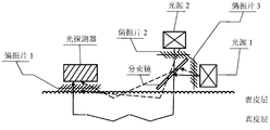
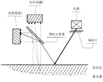
- 14-27 are schematic diagrams showing the structure of a vital sign signal measuring device in several embodiments of the present invention.
- the vital sign detecting device and method referred to in the present specification can be applied to various fields including, but not limited to, medical diagnosis (eg, Heart disease, blood disease, respiratory diseases, etc., medical care (such as intensive care, newborn care, etc.), exercise monitoring (such as long-distance running, sprinting, swimming, horse riding, etc.), health monitoring (such as health monitoring of infirm individuals) ), animal protection (such as tracking and protection of rare wild animals, pet care and maintenance), fat-reducing shaping (such as weight loss for overweight people, shaping of bodybuilders).
- medical diagnosis eg, Heart disease, blood disease, respiratory diseases, etc., medical care (such as intensive care, newborn care, etc.), exercise monitoring (such as long-distance running, sprinting, swimming, horse riding, etc.), health monitoring (such as health monitoring of infirm individuals) ), animal protection (such as tracking and protection of rare wild animals, pet care and maintenance), fat-reducing shaping (such as weight loss for overweight people, shaping of bodybuilders).
- medical diagnosis eg, Heart disease, blood
- the vital sign signal detecting device involved in the present specification can collect vital signs signals of living bodies, such as pulse, blood pressure, blood oxygen, heart rate, body temperature, HRV, BPV, brain waves, ultra-low frequency waves emitted by the human body, breathing, musculoskeletal state, Physical and chemical information such as blood sugar, blood lipids, blood concentration, platelet content, height, weight, etc., and the signal is processed and transmitted to a server or terminal.
- the vital sign signal detecting device can also combine the historical data provided by the external data source and the real-time measured vital sign signal data to obtain appropriate motion suggestions and characterize them in an appropriate representation manner.
- the vital sign signal detecting device can emit light to irradiate the living body, collect the light signal reflected and scattered by the living body, and obtain the vital sign signal of the living body after being processed.
- the motion/vibration of the living body itself will bring noise to the measured vital sign signal, consider obtaining multiple vital sign signals, and obtain the vital sign signal after noise removal according to the difference between different signals with a specific algorithm.
- the vital sign signal detecting device can collect two or more signals and perform corresponding denoising processing to obtain a relatively accurate vital sign signal.
- FIG. 1 is a diagram showing an application example of a vital sign signal detecting system.
- the application of the vital sign signal detection system may include detecting a vital sign signal of a living body, performing subsequent processing to obtain a corresponding physical parameter, storing and displaying a physical parameter.
- the vital sign signal detection application system may include, but is not limited to, a measurement device 101, a terminal device 102, a network 103, an external data source 104, and a server 105. Measurement device 101, terminal device 102, external data source 104, and server 105 can each communicate directly or indirectly and in both directions over network 103.
- the measuring device 101 can be mainly used to detect and collect vital signs signals of living bodies.
- the device can collect vital signs signals of the user during exercise.
- the measuring device 101 may be a medical detecting device, may be a home detecting device, may be a handheld device, or may be a wearable device.
- the medical testing device can include, but is not limited to, a blood pressure measuring device, a pulse measuring device, an electrocardiographic monitoring device, and the like.
- Home testing equipment may include, but is not limited to, a home sphygmomanometer, a home pulsometer, a home ECG detector, and the like.
- Handheld devices may include, but are not limited to, handheld pulse oximeters, handheld heart rate monitors, sports equipment with heart rate measurement functions such as balls, rackets, clubs, oars, treadmills, bicycles, and the like.
- Wearable devices can include, but are not limited to, watches, glasses, earphones, wristbands, belts, shoulder straps, rings, necklaces, and the like.
- the above description is only for the possible form of the measuring device 101, and does not limit its scope of application.
- the measurement device 101 may also be in other forms, such as a mouse, a Global Position System (GPS), a mattress, and the like.
- GPS Global Position System
- the terminal device 102 can be primarily used to display information.
- the terminal device 102 can be a personal computer, can be a smart TV, can be a video phone, can be a mobile device, such as a mobile phone, a tablet computer, a smart watch, etc., or can be other devices with a display function, such as an electrocardiograph, Sports recorders, etc.
- the terminal device 102 can be local (eg, the smart watch can be a measurement device and the display can be a terminal device), which can be remote.
- the manner in which the terminal device 102 displays information may include, but is not limited to, digital, graphic, curved, language broadcast, and the like.
- the information display of the terminal device 102 may be real-time or non-real-time.
- the measurement device 101 can be the same device as the terminal device 102, with the functionality to collect, process, and display information.
- Network 103 can be used to implement communication between measurement device 101, terminal device 102, external data source 104, and server 105.
- Network 103 can be a single network or a hybrid of multiple networks.
- the network 103 can be a local area network, can be a wide area network, and can be a personal network.
- the network 103 can be a wireless network or a wired network (such as a telephone network, a television network, etc.).
- Network 103 may include a variety of network access points, such as wired or wireless access points, base stations or network switching points, and the like. The above is only a description of the possible forms of the network 103, and does not limit its scope of application.
- the communication between the measurement device 101, the terminal device 102, the external data source 104, and the server 105 may be wired or wireless, or a portion of the devices may be connected in a wired manner. The devices are connected wirelessly.
- External data source 104 can be used primarily to provide various external data.
- External data refers to other information that has a correlation with the measurement device 101 detecting the acquired data.
- the external data may be individual identification information such as name, identification number, contact information, address, educational background, religious beliefs, emergency contacts, and the like that facilitate individual identification.
- the external data may be individual medical record information, such as a disease treatment record, a medication record, a medical record, and the like, and the medical record of the individual concerned.
- the external data may be individual health record information, such as heart rate records, blood pressure records, weight records, body fat rate records, etc., which may reflect the individual's health history.
- External data can be individual life record information such as breakfast ingredients, water consumption, fruit consumption Quantity, meat consumption, etc.
- External data can be various statistical information for a specific target group, such as the average height of children in the administrative area, the average weight of the newborn, and the average age of the pregnant woman.
- the external data can also be a variety of a priori description materials (such as textbooks, papers, medical product manuals, drug use instructions, etc.).
- the external data source 104 may be a database of a hospital, a pet archive of a pet hospital, an animal information database of an animal protection organization, and the like, and may be a personal computer, a mobile phone, or a library.
- the individuals mentioned above may include, but are not limited to, individuals, pets, rare animals, experimental animals, etc., and generally refer to all individuals with vital signs.
- the external data may include vital sign information for a group having a certain similarity to the user, and the certain similarities referred to herein may include gender, skin color, age, height, weight, health status, medical record, and the like.
- Server 105 can be used primarily to store information.
- Server 105 may be local storage and may be cloud storage including, but not limited to, private clouds and public clouds.
- the information stored by the server 105 may be the vital sign information transmitted by the measuring device 101, may be the processed information sent by the terminal 102, and may be the individual record information sent by the external data source 104.
- the above description of the server 105 is only possible embodiments and is not intended to limit its scope.
- server 105 can be integrated with terminal device 102 and can also function as external data source 104.
- the measuring device 101 can transmit the data to the terminal 102, the external data source 104, and the server 105 through the network 103 for subsequent processing, and can also receive various instruction information from the terminal 102, the external data source 104, and the server 105. Corresponding information collection and transmission.
- the terminal device 102 can receive the information collected by the measurement device 101, and can send the request information to the external data source 104.
- the reference information sent by the external data source 104 is combined with the collected information, and the data is processed to display the information in an appropriate manner.
- the processed information can be sent to the server 105 for storage.
- the measuring device 101 is an earphone with a heart rate detecting function that collects a heart rate signal of an athlete during running and sends it to a server 105, such as a personal computer, and the server 105 sends a request message to the data source 104 requesting to send the individual.
- a server 105 such as a personal computer
- the server 105 sends a request message to the data source 104 requesting to send the individual.
- the server 105 processes the collected data and combines the historical data to obtain motion suggestions, such as maintaining the current speed, speeding up, etc., and sending it to the terminal 102, such as a tablet and a headset of the coach, which broadcasts the motion suggestion voice to athlete.
- the measurement device 101 can include, but is not limited to, an execution module 200, a control module 205, and an energy supply module 206.
- the execution module 200 can further include, but is not limited to, an acquisition module 201, a processing module 202, a storage module 203, and an output module 204.
- Execution module 200 can be used primarily to perform acquisition, processing, storage, and output operations.
- the control module 205 can be mainly used to control the operation of the execution module 200, and can control the opening and closing of the power supply module 206.
- the power supply module 206 can Mainly used to provide energy supply for the execution module 200 and the control module 206. Two-way communication between the execution module 200, the control module 205, and the power supply module 206 is possible.
- the acquisition module 201 of the execution module 200 can be mainly used to detect and collect vital sign signals of living bodies.
- the signal collected by the acquisition module 201 may be collected by photoelectric means, such as photoplethysmography (PPG), or may be collected by other means.
- the acquisition method can be continuous acquisition or interval collection.
- the acquired signals can be single or multiple signals combined.
- Processing module 202 can be used primarily to process signals. Processing of the signal by processing module 202 may include, but is not limited to, one or more of noise cancellation, signal analysis, and signal characterization.
- the processing module 202 can process the information collected by the collection module 201, and can also process the information stored in the storage module 203. Processing module 202 is not required and may be included in server 105 or terminal 102 of FIG.
- the storage module 203 can be mainly used to store information.
- the storage module 203 may store information by using an electrical energy method (for example, RAM, ROM, etc.), and may store information by using magnetic energy (such as a hard disk, a floppy disk, a magnetic tape, a USB disk, etc.), and may be stored by electro-optic (such as a CD). , DVD), can be stored by magneto-optical (such as magneto-optical disc), or can be stored by other physical means (such as using paper storage).
- the storage module 203 can store the information collected by the collection module 201, and can also store the information processed by the processing module 202.
- the storage module 203 is not required, and the storage function can be implemented by the server 105 or the terminal 102 of FIG.
- the output module 204 can be mainly used to complete the information output, and can output the information collected by the acquisition module 201, and can also output the information processed by the processing module 202, and can also output the information stored by the storage module 203.
- the output module 204 can communicate the above information to the server 105, the terminal 102, or the external data source 104 via the network 103.
- the signal form output by the output module 204 can be in the form of numbers, graphics, voice, video, audio, and the like.
- the output may be real-time or non-real-time, and may be output by the measuring device 101 or may be outputted by other external devices after sending the request information.
- the output module 204 can support wired communication standards such as telephone, television, etc., and can also support wireless communication standards such as Bluetooth, infrared, RF, IEEE 802.11, and the like.
- the control module 205 can be used primarily to perform various control operations of the measurement device 101.
- the control module 205 can control the acquisition frequency, the acquisition time, the acquisition mode, and the like of the acquisition module 201, and can also control the processing method of the processing module 202, and can also control whether the storage module 203 is stored or not, and can also control the output time of the output module 204.
- the output form and the like can also control the opening and closing of the energy supply module 206, such as mechanical control, electrical control, and the like. Communication of requests, command information between other devices, such as server 105, external data source 104, terminal device 102, and measurement device 101, may be accomplished by control module 205.
- the energy supply module 206 can be primarily used to be responsible for the energy supply of the measurement device 101.
- the energy supply module 206 refers to all devices that can provide energy supply.
- the energy supply module 206 can be a fuel cell, a dry battery, a battery, a solar cell, a thermoelectric cell, a bioenergy battery, or the like.
- the power supply module 206 can include a charging interface such as a microUSB, miniUSB, lighting, and the like.
- Step 301 the vital sign signal is taken set.
- the acquired signal may be a signal derived from direct measurement of a living body, such as a signal measured using the PPG method (also referred to as a PPG signal).
- the acquired signals may also be external data from external data source 104 via network 103, such as personal identification information, personal health records, personal life records, and the like.
- the collected signals may also be information from the server 105 over the network 103, such as historical information uploaded to the server 105, and the like.
- Step 301 can be completed by acquisition module 201.
- the collected signals are analyzed and processed.
- the signal for performing the analysis processing may be the signal collected in step 301, or may be the signal sent by the storage module 203 after transmitting the request to the storage module 203.
- the analysis processing of the signals may include, but is not limited to, noise removal, signal analysis, signal characterization.
- Step 302 can be completed by processing module 202.
- the information is stored.
- the stored information may be the signal collected in step 301, or may be the signal analyzed in step 302.
- Step 303 can be completed by storage module 203.
- the signal is output.
- the output signal may be a signal collected by the acquisition module 201, a signal processed by the processing module 302, or a signal stored by the storage module 203.
- Step 304 can be completed by output module 204.
- FIG. 4 is a schematic structural diagram of an acquisition module 201 in an embodiment of the present invention.
- the acquisition module 201 can be mainly used to acquire a desired signal.
- the acquisition module 201 can include, but is not limited to, a light-emitting element 401, a light-sensitive element 402, a drive circuit 403, a signal amplifier 404, and an A/D converter 405.
- the light emitting element 401 can generate light radiation onto the living body.
- the light-emitting element 401 may be a heat radiation source or an excitation radiation source such as a light-emitting diode (LED).
- LED light-emitting diode
- the light emitted by the light-emitting element 401 may be a single wavelength or a different wavelength of light, and may be in a polarization state or a non-polarization state.
- the light-emitting time of the light-emitting element 401 may be fixed or fixed.
- the photosensitive element 402 can be used to detect light reflected and scattered by the living body and convert the detected optical signal into an electrical signal.
- the photosensitive element 402 may be a light guiding type device such as a photoresistor, or may be a photovoltaic type device such as a photodiode, a phototransistor, an optical field effect transistor, or the like, or may be a photodetector.
- the driving circuit 403 can be used to drive the light emitting element 401 to emit light.
- the signal amplifier 404 can amplify the electrical signal transmitted by the photosensitive element 402.
- the A/D converter 405 can perform analog-to-digital conversion (A/D conversion) on the collected electrical signals.
- FIG. 5 is a flow chart showing the operation of the acquisition module 201 in one embodiment of the present invention.
- the required signal is acquired.
- Step 501 can be accomplished by the light-emitting element 401 and the light-sensitive element 402.
- the light-emitting element 401 may first generate light specified by a parameter, which may be a wavelength of light, a light intensity, a phase, a polarization state, or the like. Light illuminates the living body, and the living body produces reflection, absorption, and scattering.
- the photosensitive element 402 can detect the reflected and scattered light and convert the optical signal into an electrical signal.
- the acquired signal is amplified as needed.
- the acquired signal does not need to be amplified, and step 502 may not be performed.
- Step 502 can be accomplished by signal amplifier 404.
- the amplified signal is subjected to A/D conversion.
- the analog signal is collected, and the subsequent processing of the processing module 202 and the storage of the storage module 203 need to be digital signals, so analog-to-digital conversion is performed to obtain a digital signal.
- Step 503 can be performed by A/D converter 405.
- the signal is output.
- the output signal may be output to the processing module 202 for subsequent processing, and may be output to the storage module 203.
- the storage may also be output to the output module 204 for transmission to the server 105, the terminal 102, or the external data source 104.
- FIG. 6 is a schematic structural diagram of a processing module 202 in an embodiment of the present invention.
- the processing module 202 can be primarily used for analysis processing of signals.
- the processing module 202 can include, but is not limited to, a noise cancellation unit 601, a function configuration unit 602, a signal analysis unit 603, and a signal characterization unit 604.
- the noise cancellation unit 601 can perform noise removal on the information collected by the acquisition module 201.
- the signal collected by the acquisition module 201 may be two signals having correlation, and the two signals need to be removed by noise to remove signals unrelated to the heart rate, such as motion or vibration signals during human motion.
- the function configuration unit 602 can perform function configuration, and the configurable functions include, but are not limited to, heart rate detection, motion signal detection, health signal detection, and the like.
- the signal analysis unit 603 can parse the signal.
- the acquisition module 201 transmits an electrical signal, and after performing a certain analysis on the electrical signal, the desired vital sign signal can be obtained.
- the signal analysis unit 603 can be configured to analyze the electrical signal into a pulse signal, a heart rate signal, an oxygen consumption amount signal, a fat consumption amount signal, and the like, depending on the functional configuration.
- Signal characterization unit 604 can characterize the parsed signal.
- the characterization can include, but is not limited to, digital characterization, curve characterization, graphical characterization, real-time speech characterization, video characterization, and the like.
- FIG. 7 is a flow chart showing the operation of the processing module 202 in one embodiment of the present invention.
- the collected signal is subjected to noise removal to obtain a desired electrical signal.
- the noise removal processing may include, but is not limited to, a single parameter removal method, a multi-parameter removal method, a wavelet analysis, a Fourier transform, an adaptive filtering method, and the like.
- Step 701 can be completed by noise cancellation unit 601.
- Step 702 performing function configuration, and selecting a processing function to be implemented by the processing module 202.
- Step 702 can be completed by function configuration unit 602.
- the electrical signals are resolved into different signals according to different functional configurations.
- Step 703 can be completed by signal parsing unit 603.
- Step 704 the signals are characterized as different forms of signals according to different characterization requirements.
- Step 704 can be accomplished by signal characterization unit 604.
- the execution of step 701, step 702, step 703 and step 704 may be performed sequentially, or step 702 may be performed first, and after the function configuration is completed, step 701, step 703 and step 704 are sequentially executed.
- a single parameter method can be used to correct a single signal acquired by a specific receiving signal processing algorithm, or a multi-parameter method, that is, multiple receiving signals can be collected, one or more of which are collected.
- the received signal is used as a reference signal, and the noise is eliminated by a specific algorithm.
- FIG. S 1 and S 2 are input signals, and Adaptive Filter is a filter that can adjust or correct the signal.
- the mixer can compare the input signals and finally output the signal. The process can be expressed as:
- w represents the coefficient of the filter and can be based on the output signal auto-adjust.
- S 1 may contain vital sign information and noise information
- S 2 may contain noise information but no vital sign information.
- S 1 may contain vital sign information and noise information
- S 2 also contains vital sign information and noise information, and the ratios of vital sign information and noise information in S 1 and S 2 are different according to The feedback solves the appropriate filter coefficients w to obtain the desired signal.
- the input signals mentioned here can contain different types of signals.
- the input signal may include an optical signal, an electrical signal, a magnetic signal, a sound signal, a temperature signal, a displacement signal, or the like, or a combination of the plurality thereof.
- the input signal may be a signal received by the receiving end (for example, an optical signal received by the receiving end, an electrical signal, a magnetic signal, a sound signal, a temperature signal, and/or a displacement signal, etc.), or may be a signal received by the receiving end after being processed.
- the obtained signal (for example, an optical signal, an electrical signal, a magnetic signal, a sound signal, a temperature signal, and/or a displacement signal received by the receiving end, converted into an optical signal, an electrical signal, a magnetic signal, a sound signal, a temperature signal, and/or Displacement signal, etc.).
- the receiving end may be different types of sensors, which may include, but are not limited to, photoelectric sensors, displacement sensors, acceleration sensors, shock sensors, mechanical sensors, temperature sensors, air pressure sensors, and the like.
- the types of photoelectric sensors include, but are not limited to, diffuse reflection type photoelectric sensors, through-beam type photoelectric sensors, distance type photoelectric sensors, slot-shaped photoelectric sensors, fiber optic photoelectric sensors, and the like.
- the input signal may not be limited to S 1 and S 2 and may include more than two input signals, each of which may be from a signal of one or more sensors.
- the coefficient w of the filter may be obtained according to the negative feedback of the output signal, or may be obtained according to the forward feedback of other input signals, and further, may be based on the negative feedback of the partial output signal and the forward feedback of the partial input signal.
- the coefficient w of the filter may be obtained by system calculation, may be set by a user, or may be obtained by wired or wireless means from an external device or device or obtained by other means. For example, in a day, the vital signs of the human body behave differently in different time periods, and the corresponding filter coefficients w can be selected at different time periods in a day, or corresponding parameters can be set in different dates, months or seasons. w.
- the input signals S 1 and S 2 may be optical signals containing vital sign information and noise information, respectively.
- the received light can carry information of the layer of the medium.
- a beam of light strikes a medium (solid, liquid, or gas)
- a portion of the light may be reflected by the medium, and a portion of the light may penetrate or be absorbed by the medium.
- the reflection, absorption, transmission, etc. of light depends on the properties of the medium on the light propagation path.
- human skin tissue is composed of epidermis, dermis, subcutaneous tissue, and skin appendage.
- the epidermis contains no blood vessels, and the thickness of the epidermis varies depending on the location of the epidermis. Most of the epidermis has a thickness of about 100 ⁇ m.
- the dermis is located between the epidermis and the subcutaneous tissue and is mainly composed of connective tissue, which is divided into a papillary layer and a reticular layer from the outside to the inside.
- the nipple layer is rich in capillaries.
- the reticular layer contains many large blood vessels, which are mainly located at the bottom of the dermis.
- a human skin tissue composed of a plurality of layers of different structures has optical properties equivalent to a chaotic medium having high scattering properties.
- backscattered light can include ballistic photons, serpentine photons, and diffuse photons. Among them, ballistic photons and serpentine photons return to the skin surface after a small amount of scattering and absorption in the skin tissue.
- This part of the scattered light penetrates shallowly, usually does not reach the dermis layer, and hardly carries the internal tissue structure information of the skin.
- the diffuse photons are returned to the surface of the skin after multiple scattering in the skin.
- This part of the scattered light usually passes through the dermis and carries information about the internal tissue structure of the skin, for example, the increase or decrease of blood flow in large blood vessels in the dermis.
- the specularly reflected light has the same polarization.
- the ballistic photons and the serpentine photons with less scattering times have the same polarization, and the diffuse photons with more scattering times have no polarization.
- the scattered light is collectively referred to as superficial reflected light.
- the signals reflected by the living body (for example, the skin) in the present specification may include surface reflected light of a living body (for example, skin), and may also include scattered light scattered by living body (for example, skin) tissue, or may also include skin surface reflection. Light and scattered light scattered by skin tissue.
- the transmission and reception of optical signals can be accomplished by a PPG sensor, which can include a number of light sources and photodetectors.
- the photodetector close to the skin can detect this change: when the blood vessel is filled, the blood absorbs the light the most, the detector detects the minimum intensity of the emitted light, and when the blood vessel contracts, the blood absorbs the light the least, the detector The detected intensity of the emitted light is the largest.
- the PPG sensor can trace the fluctuation signal formed by the change of the blood vessel internal volume, thereby obtaining information related to vital signs (such as, but not limited to, pulse wave, heart rate, blood pressure, etc.).
- vital signs such as, but not limited to, pulse wave, heart rate, blood pressure, etc.
- the measurement of the pulse wave can be achieved by obtaining different input signals by one or more PPG sensors.
- the input S 1 signal may contain a PPG signal, and the S 2 signal does not include a PPG signal.
- the ratio of the PPG signal to the noise signal contained in the input S 1 signal may be different from the ratio of the PPG signal and the noise signal contained in the S 2 signal.
- the detection of vital signs is not limited to pulse waves, and may also include a combination of one or more of blood pressure, blood oxygen saturation, heart rate variability, heart murmur, and the like.
- the vital signs information contained in the input signal includes, but is not limited to, the determination of various physiological parameters of the living body, such as but not limited to height, weight, vital capacity, heart beat parameters, blood glucose level, blood viscosity measurement, vasodilation pressure, vasoconstriction pressure.
- blood flow parameter measurement PPG letter No. wave peak trough, ECG signal peak trough, pulse rate, heart rate, blood lipid content, vascular tone, skin tension, brain wave frequency, gastrointestinal motility, hepatobiliary organ morphology, digestive tract mucosal parameters, antibody content, biological enzyme content, etc. kind or more.
- the input signal can be obtained containing different vital signs and information and noise information S 1 of S 2.
- the input signals S 1 and S 2 are the light and the tissue depth related to skin depth. For example, if the light penetrates deep into the skin and there may be blood vessels in the light-transmitting area, the input signal may contain a PPG signal. If the depth of the light penetrates into the skin is shallow, the light-transmitting area may not have blood vessels, and the input signal may not Contains PPG signals, or the PPG signal in the input signal is relatively small.
- the average depth of photons deep into the tissue is related to the distance from the source to the detector. For example, when the distance between the light source and the detector is relatively close, the average depth of the photon deep into the tissue is shallow, and the information of the deep medium carried is less. When the distance between the light source and the detector is far, the average depth of the photon deep into the tissue is deep, carrying The deep media has more information. In skin tissue, the deeper the average depth of photons deep into the tissue, the more vital sign information (eg, PPG signals) are detected. By using the difference between the position of the light source and the detector, signals with different proportions of pulse wave components can be obtained.
- PPG signals vital sign information
- Figure 10 is a schematic view showing the structure of a sensor utilizing the difference in position between the light source and the detector.
- the sensor can contain a light detector and two light sources.
- a photodetector may refer to a device capable of receiving an optical signal of a certain wavelength and reading information of the optical signal, such as a photosensor.
- the light source referred to herein may contain only a single wavelength of light, or may contain light of a certain wavelength range.
- a light source may have a wavelength of 700 nm or other single wavelength, or may be 600 nm to 700 nm or other wavelength range.
- the light referred to herein may be light in the visible range, such as, but not limited to, red light, yellow light, blue light, green light, violet light, etc., or may be non-visible light, for example, infrared light, ultraviolet light, or the like.
- the light detector and the light source 1 and the light source 2 can both be in close contact with the skin.
- the light detector and the light source 1 and the light source 2 can be located in a straight line.
- the light source 1 and the light source 2 may be located on the same side of the photodetector.
- the distance between the light source 1 and the photodetector is relatively long, and the distance between the light source 2 and the photodetector is relatively close.
- the distance between the light source 1 and the photodetector is greater than the distance from the light source 2 to the photodetector.
- the light source 1 and the light source 2 may alternately emit light beams, or may simultaneously emit light beams.
- the intensity of the light source 1 and the light source 2 can be adjusted.
- the intensity of the light source can be automatically adjusted according to the brightness of the environment and the intensity of the external light, or can be fed back according to the intensity of the light signal received by the light detector. Adjusting the intensity of the light source can also be adjusted according to external input.
- the light-emitting wavelengths of the light source 1 and the light source 2 may be the same or different.
- the light beams emitted by the two light sources reach the skin, due to the different distances of the light source 1 and the light source 2 to the light detector, the light beams emitted by the light source 1 and the light source 2 have different average depths to the skin tissue, and the vital signs carried (for example, The magnitude of the signal of the pulse wave component (for example, the PPG signal) is also different. For example, if the distance between the light source 1 and the photodetector is far, the average depth of the light beam emitted by the light source 1 to the skin tissue is large, and the vital signs carried by the light signal scattered by the light beam emitted by the light source 1 are reflected by the skin. The proportion of the (for example, pulse wave) component signal is large.
- the distance between the light source 2 and the photodetector is relatively short, and the average depth of the light beam emitted by the light source 2 to the skin tissue is small, and the pulse wave component signal carried by the light signal scattered by the light beam emitted by the light source 2 is reflected by the skin.
- the proportion is small.
- the motion information beam carrying vital signs information is received by the different proportions of the photodetector, the received signal is a photo signal and a photo signal 1 2, respectively labeled as the I 2 and I 1, the photo signal received signals 1 and 2 may be photo Directly as the input signals S 1 and S 2 in Fig. 8, it can also be used as input signals S 1 and S 2 after certain processing and conversion.
- the constituent elements of the sensor may include one photodetector and two light sources, two photodetectors and one light source, two photodetectors and two light sources (for example, the light source 1 and the photodetector 1 constitute the sensor 1, the light source 2
- the photodetector 2 constitutes a sensor 2), and a combination of any number of photodetectors and light sources.
- the distance between the constituent elements of the sensor and the skin is not limited to being in close contact with the skin surface, all at a distance above the skin, with one or more light sources and one or more detectors located a distance above the skin.
- the distance above the skin between different light sources or between different light detectors or between different light sources and different detectors may be the same or different.
- the distance between the sensor constituent elements and the skin may be 2-10 mm, and more preferably, the distance between the sensor constituent elements and the skin may be It is 7mm.
- the distance between the light source and the photodetector 1 may be greater than the distance between the light source and the photodetector 2, preferably, the distance between the light source and the photodetector 1 is greater than 5 mm.
- the distance from the photodetector 2 is less than 5 mm, and more preferably, the distance of the light source from the photodetector 1 is greater than 8 mm.
- the distance between the light source 1 and the photodetector 1 may be greater than the distance between the light source 2 and the photodetector 2, preferably, the distance between the light source 1 and the photodetector 1 is greater than 5 mm, the distance between the light source 2 and the photodetector 2 is less than 5 mm, and more preferably, the distance between the light source 1 and the photodetector 1 is greater than 8 mm.
- the relative position between the photodetector and the light source can be different.
- the two light sources can be located on one side of the detector at the same time, and the two light sources can also be located on both sides of the detector.
- the relative position between the photodetector and the light source may be that two detectors are located on one side of the light source, or two detectors may be located on both sides of the light source.
- the relative position between the photodetector and the light source may be that the photodetector 1 and the photodetector 2 are located between the two light sources, or may be photodetectors. 1 and the photodetector 2 are respectively located on two sides of the two light sources, the photodetector 1 and the photodetector 2 are located on one side of the two light sources at the same time, or the photodetector 1 is located on one side of the two light sources, and the photodetector 2 Located between two light sources.
- Light source and light detection when the component is any number of photodetectors and light sources The relative position of the device can be determined according to actual needs.
- Fig. 11 is a view showing the structure of a sensor for changing the direction of light propagation using a lens in the present invention.
- the sensor can include a photodetector, two light sources, and a lens.
- the light source 1 can be closely attached to the skin, the photodetector can be located at a distance above the skin, and there can be a lens between the light source 2 and the skin, and the light source 1 and the light source 2 can be located on the same side of the photodetector.
- the lens can be used to change the direction of the light beam emitted by the light source 2 so that the light angle is at an angle to the skin.
- the angle of the angle can be any value, for example, 0°-180°, the lens type mentioned here. These include, but are not limited to, concave lenses, convex lenses, plano-convex lenses, plano-concave lenses, meniscus lenses, or other devices having directions that change light, such as light guides or prisms having a shape (such as, but not limited to, triangular prisms).
- the distance between the light source 1 and the photodetector is relatively long, and the distance between the light source 2 and the photodetector is relatively close.
- the light source 1 and the light source 2 can alternately emit light beams or simultaneously emit light beams.
- the light-emitting wavelengths of the light source 1 and the light source 2 may be the same or different.
- the distance between the light source 1 and the photodetector is long, and the incident angle of the light entering the skin is large, the light beam emitted by the light source 1 penetrates deep into the skin tissue, and the light beam emitted by the light source 1 is scattered by the skin.
- the ratio of the pulse wave component signals carried by the optical signal is large.
- the distance between the light source 2 and the photodetector is relatively short, and the incident angle of the light entering the skin is small, the depth of the light beam emitted by the light source 2 is deep into the skin tissue, and the light beam emitted by the light source 2 is scattered by the skin.
- the proportion of the pulse wave component signal carried by the optical signal is small.
- the received signals are the photo signal 1 and the photo signal 2, labeled I 1 and I 2 , respectively.
- I 1 and I 2 can be used as the signal to be processed and the reference signal, respectively, and the motion artifacts are removed by the adaptive noise cancellation algorithm described in FIG.
- one or more lenses can be added to the sensor element.
- a lens or other similar device that changes the direction of the light path
- a lens may be located between all of the light detectors and the skin, or between a portion of the light detector and the skin, between all of the light sources and the skin, or in portions Between the light source and the skin, it can be located only between the light detector and the skin, or just between the light source and the detector.
- different Different types of lenses or other similar devices that change the direction of the light path
- Changing the way the signal is collected can also be achieved by the polarization characteristics of the light source.
- the light source After the light source is irradiated to the skin, light will reflect on the surface of the skin, and the rest will be transmitted into the interior of the tissue, which will scatter or absorb events in the tissue. After multiple scattering and absorption, some of the light will later re-escape the skin in the form of scattered light, which becomes backscattered light. This part of the light carries a wealth of underlying tissue information that is mixed with the reflected light from the skin surface to form a reflected signal. The skin surface reflected light and the backscattered light have different polarization characteristics.
- the incident light is linearly polarized light that satisfies certain conditions
- the reflected light on the skin surface is still linearly polarized, and the backscattered light entering the tissue substantially loses polarization characteristics due to multiple scattering events. Therefore, at least two different signals can be obtained by utilizing different polarization characteristics of the skin surface reflected light and the backscattered light.
- Figure 12 is a block diagram showing the structure of a sensor utilizing the polarization characteristics of a light source in the present invention.
- the sensor consists of a light source that produces linearly polarized light and two light detectors that detect light of different polarization characteristics.
- the polarization direction of the linear polarization of the light source may be a direction perpendicular to the incident surface, a direction parallel to the incident surface, or a direction at a certain angle to the incident surface.
- the light source and the photodetector can both be at a distance from the skin, or they can all adhere to the surface of the skin, and the distance between the two detectors is very close.
- both the photodetector 1 and the photodetector 2 acquire signals when the light source emits light, and obtain the photoelectric signal 1 and the photoelectric signal 2.
- Both the photoelectric signal 1 and the photoelectric signal 2 contain superficial reflected light and multiple backscattered light of the living body.
- the photodetector can collect reflected light from the skin surface, less backscattered light, and multiple backscattered light. Since the superficial reflected light is still linearly polarized light and the plurality of backscattered lights are unpolarized light, the superficial reflected light and the plurality of backscattered light components contained in the photoelectric signal 1 and the photoelectric signal 2 have different characteristics.
- the photodetector can acquire less backscattered light and multiple backscattered light without scattered light on the skin surface. Since the backscattered light is still linearly polarized light and the plurality of backscattered lights are unpolarized light, the lesser backscattered light and the plurality of backscattered light components included in the photoelectric signal 1 and the photoelectric signal 2 have Different characteristics.
- the size of the superficial reflected light and the multiple backscattered light can be calculated by different characteristics of the superficial reflected light and the multiple backscattered light. Based on the calculated values, motion artifacts can be removed by an adaptive filtering algorithm.
- the constituent elements of the sensor may include one photodetector and two light sources, two photodetectors and one light source, two photodetectors and two light sources (for example, the light source 1 and the photodetector 1 constitute the sensor 1, the light source 2
- the photodetector 2 constitutes a sensor 2), or any other combination of photodetectors and light sources.
- sensor elements that utilize polarization characteristics of the light source can include, but are not limited to, one or more light sources, one or more light detectors.
- a light source for example, a laser
- a polarizer is provided to generate polarized light.
- a polarizing plate may be disposed on all of the photodetectors, or a polarizing plate may be disposed on a part of the photodetectors, the same polarizing plate may be disposed on different detectors, or different polarizing plates may be disposed on different detectors. (For example, linear polarizers set to be perpendicular to each other in the polarization direction).
- Polarizers may be disposed on all light sources, polarizers may be disposed on some of the light sources, the same polarizers may be disposed on different light sources, or different polarizers may be disposed on different light sources (eg, the polarization directions are perpendicular to each other) Linear polarizer).
- the type of the polarizer is not limited to linear polarization, and may also include a circularly polarizing plate, an elliptically polarizing plate.
- the information of the vital signs contained in the optical signal collected by the photodetector is also related to the angle at which the light is irradiated on the surface of the living body.
- skin surface reflected light and backscattered light are related to the angle of reception.
- the intensity distribution characteristics of the backscattered light are independent of the incident angle. In the case of various incident angles, the backscattered light energy reaches a maximum value when the receiving angle is 90°.
- the light intensity distribution of the surface-emitting light which occurs due to the difference in refractive index, the spatial shape of which is spindle-shaped, and reaches the maximum value of the energy at the theoretical specular reflection, and as the receiving angle is further increased (or decreased), It will cause a drop in the received energy.
- Figure 14 is a schematic view showing the structure of a sensor utilizing the relationship between the reflected light of the skin surface and the backscattered light and the angle of reception.
- the sensor can contain two photodetectors and one light source. The two photodetectors and the light source can both be at a distance from the surface of the skin, and the distance between the two detectors can be very close or a distance.
- the light incident angle of the light source may be ⁇ , and the magnitude of ⁇ may be 0-90°.
- the photodetector 1 can be located at a theoretical specular reflection on the plane defined by the incident light and the normal, and the angle between the line connecting the photodetector 1 and the incident point and the normal can also be ⁇ .
- the photodetector 2 can be located near the normal of the incident light, i.e., a region that is closer to the incident normal to the incident light.
- the angle between the photodetector 2 and the skin interface is 60°-120°, and more preferably, the angle between the photodetector 2 and the skin interface is 80°-100°, and more preferably, the photodetector 2 is The angle of the skin interface is 90°, that is, the photodetector 2 is located directly above the normal of the incident light.
- the light detector and the light source are working, after the light beam from the light source reaches the skin, a part of the light is reflected by the skin surface to form a reflected light on the skin surface, and a part of the light penetrates the skin epidermis layer and/or penetrates the skin dermis layer to form backscattered light. .
- Both the photodetector 1 and the photodetector 2 can acquire signals when the light source emits light, and can simultaneously acquire signals or alternately acquire signals, and the collected signals are photoelectric signal 1 and photoelectric signal 2, which are respectively labeled as I 1 and I 2 . . Since the photodetector 1 is located in the direction in which the surface reflected light is strongest, the reflected light component of the skin surface in the photoelectric signal 1 obtained by the photodetector 1 is large. Since the photodetector 2 is located in the strongest direction of the backscattered light, the backscattered light component in the photodetection signal 2 collected by the photodetector 2 is large.
- the photoelectric signal 1 is I 1
- the photoelectric signal 2 is I 2
- I 2 and I 1 are used as the input signals S 1 and S 2 , respectively, and the motion artifacts are removed by the adaptive noise cancellation algorithm of FIG. 8 or similar.
- the above description is only specific embodiments of the present invention, and the scope of protection of the present invention is not limited to the embodiments described above.
- the above can be described without any creative work.
- the implementation is subject to some modifications and variations, which are also within the scope of the present invention.
- the position of the photodetector and the light source can be adjusted, so that more light reflected from the skin surface is obtained in some photodetectors, and more backscatter signals are obtained in some photodetectors, thereby obtaining a plurality of signals containing different vital signs.
- the input signal of the component can be adjusted, so that more light reflected from the skin surface is obtained in some photodetectors, and more backscatter signals are obtained in some photodetectors, thereby obtaining a plurality of signals containing different vital signs.
- the distance between the light source and the detector can be changed as described above, or the polarization characteristics of the light source can be utilized, or the relationship between the reflected light of the skin surface and the backscattered light and the receiving angle can be utilized.
- the above technical solutions can also be used in combination.
- the polarization characteristics of the light source can be used in combination with the relationship between the skin surface reflected light and the backscattered light and the receiving angle, as shown in FIG.
- the sensor can contain two photodetectors, one light source and three polarizers. The two photodetectors and the light source can both be at a distance from the surface of the skin, and the distance between the two detectors can be very close or a distance.
- the polarization directions of the polarizing plate 1 and the polarizing plate 3 may be the same, and the polarization direction of the polarizing plate 2 may be perpendicular to the polarization directions of the polarizing plate 1 and the polarizing plate 3.
- the light incident angle of the light source may be ⁇
- the magnitude of ⁇ may be 0-90°.
- the photodetector 1 can be located at a theoretical specular reflection on the plane defined by the incident light and the normal, and the angle between the line connecting the photodetector 1 and the incident point and the normal can also be ⁇ .
- the photodetector 2 may be located near the normal of the incident light.
- the angle between the photodetector 2 and the skin interface is 60°-120°, and more preferably, the angle between the photodetector 2 and the skin interface is 80°. 100°, more preferably, the angle between the photodetector 2 and the skin interface is 90°, ie the photodetector 2 is located directly above the normal.
- the angle between the photodetector 2 and the skin interface is 90°, ie the photodetector 2 is located directly above the normal.
- Both the photodetector 1 and the photodetector 2 can acquire signals when the light source emits light, and can simultaneously acquire signals or alternately acquire signals, and the collected signals are photoelectric signal 1 and photoelectric signal 2, which are respectively labeled as I 1 and I 2 . . Since the polarization directions of the polarizing plate 1 and the polarizing plate 3 are the same, the photoelectric signal 1 collected by the photodetector 1 includes a parallel component of the parallel component of the reflected light of the skin surface and the backscattered light, and the photodetector 1 is located in the incident beam.
- the photoelectric signal 2 collected by the photodetector 2 does not include the reflected light of the skin surface, and only contains the vertical component of the backscattered light, and the photodetector 2 is located at the incident light. Near the normal line, the backscattered light has a relatively strong direction, so the backscattered light component in the photoelectric signal 2 is large.
- the optical signal 1 collected by the photodetector 1 contains a large proportion of motion information and a certain proportion of vital sign information
- the optical signal 2 collected by the photodetector 2 contains a large proportion of vital sign information and a certain Proportional motion information.
- the accuracy of the input signal can be further improved.
- beam splitter The two signals can be strictly taken from the same point on the skin, which improves the correlation and ultimately improves the signal quality.
- the sensor consists of a light source that produces linearly polarized light, two light detectors that detect light of different polarization characteristics, and a beam splitter.
- the light source and the photodetector may both be at a distance from the skin, or only the light source may be at a distance from the skin, and the photodetector may be at a distance from the skin or close to the skin surface, and the two photodetectors are respectively located in the beam splitter.
- the beam splitter reflects the same component as the transmission.
- the beam splitter can split the superficial reflected light of the skin reflection into two paths.
- one path is the light reflected by the beam splitter, and is received by the photodetector 1
- one path is the light transmitted by the beam splitter. receive.
- the beam splitter can split the skin's multiple backscattered light into two paths. One is the light reflected by the beam splitter, which is received by the light detector 1. One way is the light transmitted by the beam splitter. Receiver 2 receives. When the sensor is in operation, both the photodetector 1 and the photodetector 2 acquire signals when the light source emits light, and obtain the photoelectric signal 1 and the photoelectric signal 2.
- the superficial reflected light is still linearly polarized light, and the multiple backscattered light is unpolarized light, the superficial reflected light and the multiple backscattered light components contained in the photoelectric signal 1 and the photoelectric signal 2 have different characteristics.
- the size of the superficial reflected light and the multiple backscattered light can be obtained by the characteristic calculation. According to the size of the superficial reflected light and the multiple backscattered light, the motion artifacts can be removed by FIG. 8 and similar adaptive filtering algorithms.
- a polarizing beam splitter can be used in place of the beam splitter and the polarizer to simplify the structure while retaining the function.
- the number of beam splitters may be more than one, the beam splitter may split the light emitted from the light source, or split the light reflected from the skin, or part of the beam splitter may perform light emitted from the light source. The beam splitter, part of the beam splitter splits the light reflected from the skin.
- a vital sign signal measuring device can be applied to a wearable device, a medical device, a sports device, etc., can detect various vital signs signals, can collect and signal processing, and can communicate with a terminal, a server or an external data source through a network.
- the signal can be characterized in a variety of ways. This embodiment is described in detail by taking an example of a vital sign signal measuring device mainly for detecting a heart rate signal, which is applied to an earphone.
- the heart rate measuring device may include, but is not limited to, an acquisition module, a processing module, a storage module, an output module, a control module, an energy supply module, and the like.
- the acquisition module can use the PPG method to collect signals. When the signal is collected, the motion of the body may cause great interference to the acquisition of the signal, so that the collected signal contains noise. In order to eliminate the noise of the human motion or vibration signal, it may be used.
- a multi-parameter adaptive noise cancellation method that requires at least two different signals to be input. In order to obtain two different signals, a device as shown in FIG. 17a may be used.
- the acquisition module may include one light source and two light detectors. The two light detectors and the light source are closely attached to the skin, and the three devices may be located in one piece.
- the photodetector 1 and the photodetector 2 are located on both sides of the light source.
- the distance between the photodetector 1 and the light source is relatively long, and the distance between the photodetector 2 and the light source is relatively close.
- the distance between the photodetector 1 and the light source is greater than the distance between the photodetector 2 and the light source.
- the photoelectric signal 1 and the photoelectric signal 2 are labeled as I 1 and I 2 , respectively.
- the processing module uses I 1 and I 2 as two input signals to remove motion artifacts through an adaptive noise cancellation algorithm.
- the signal after removing the motion artifacts may be stored in the storage module or outputted to the terminal, server or external data source by the output module.
- the server can further analyze and process the collected signals according to relevant historical data in the external data source, and obtain information that is interesting and easy for ordinary people to understand, such as heart rate, oxygen consumption, fat consumption, and the like.
- the terminal can display the signal in the form of numbers, curves, images, audio, video, and the like.
- a vital sign signal detecting device may include an acquisition module different from that of the first embodiment.
- the acquisition module may be a structure as shown in FIG. 17b, and the sensor includes two photodetectors and one light source.
- the two photodetectors and one light source are located at a certain distance above the skin.
- the three devices may or may not be in a straight line, and the photodetector 1 and the photodetector 2 may be located on the same side of the light source.
- the distance between the photodetector 1 and the light source is relatively long, and the distance between the photodetector 2 and the light source is relatively close.
- the distance between the photodetector 1 and the light source is greater than the distance between the photodetector 2 and the light source.
- the photodetector 1 and the photodetector 2 simultaneously collect the reflected signal when the light source emits light, and obtain the photoelectric signal 1 and the photoelectric signal 2. Since the distance between the photodetector 1 and the light source is far, the photon collected by the photodetector 1 penetrates deeper into the skin, so the photoelectric signal 1 contains more blood volume change information.
- the photoelectric signal 1 and the photoelectric signal 2 are labeled as I 1 and I 2 , respectively.
- a vital sign signal detecting device may include an acquisition module different from that of the first embodiment.
- the acquisition module is a structure as shown in FIG. 17c, and the sensor includes two photodetectors and one light source.
- the two photodetectors and one light source are located at a certain distance above the skin, and the three devices are located in a straight line or not in a straight line, and the photodetector 1 and the photodetector 2 are respectively located on both sides of the light source.
- the distance between the photodetector 1 and the light source is relatively long, and the distance between the photodetector 2 and the light source is relatively close.
- the distance between the photodetector 1 and the light source is greater than the distance between the photodetector 2 and the light source.
- the photodetector 1 and the photodetector 2 simultaneously collect the reflected signal when the light source emits light, and obtain the photoelectric signal 1 and the photoelectric signal 2. Since the distance between the photodetector 1 and the light source is far, the photon collected by the photodetector 1 penetrates deeper into the skin, so the photoelectric signal 1 contains more blood volume change information.
- the photoelectric signal 1 and the photoelectric signal 2 are labeled as I 1 and I 2 , respectively.
- a vital sign signal detecting device may include an acquisition module different from that of the first embodiment.
- the acquisition module is a structure as shown in FIG. 17d, and the sensor includes two photodetectors and one light source.
- the photodetector 1 is in close contact with the skin, and the light source and the photodetector 2 are located at a certain distance above the skin, and the photodetector 1 and the photodetector 2 are located on the same side of the light source.
- the horizontal distance between the photodetector 1 and the light source is relatively long, and the horizontal distance between the photodetector 2 and the light source is relatively close.
- the photodetector 1 and the photodetector 2 simultaneously collect the reflected signal when the light source emits light, and obtain the photoelectric signal 1 and the photoelectric signal 2. Since the distance between the photodetector 1 and the light source is far, the photon collected by the photodetector 1 penetrates deeper into the skin, so the photoelectric signal 1 contains more pulse wave information.
- the photoelectric signal 1 and the photoelectric signal 2 are labeled as I 1 and I 2 , respectively.
- a vital sign signal detecting device may include an acquisition module different from that of the first embodiment.
- the acquisition module is a structure as shown in FIG. 18a.
- the sensor includes a photodetector and two light sources having the same emission wavelength.
- the light detector and the two light sources are in close contact with the skin, and the three devices are in a straight line or not in a straight line, and the light source 1 and the light source 2 are located on the same side of the photodetector.
- the distance between the light source 1 and the photodetector is relatively long, and the distance between the light source 2 and the photodetector is relatively close.
- the light source 1 and the light source 2 alternately emit light, and the photodetector collects the reflected signal when it emits light to obtain the photoelectric signal 1 and the photoelectric signal 2. Since the distance between the light source 1 and the photodetector is far, the photon emitted by the light source 1 penetrates deeper into the skin, so the photoelectric signal 1 contains more pulse wave information.
- the photoelectric signal 1 and the photoelectric signal 2 are labeled as I 1 and I 2 , respectively.
- a vital sign signal detecting device may include an acquisition module different from that of the first embodiment.
- the acquisition module is a structure as shown in FIG. 18b.
- the sensor includes a photodetector and two light sources having the same emission wavelength.
- the light detector and the two light sources are in close contact with the skin, and the three devices are in a straight line or not in a straight line, and the light source 1 and the light source 2 are located on both sides of the photodetector.
- the distance between the light source 1 and the photodetector is relatively long, and the distance between the light source 2 and the photodetector is relatively close.
- the light source 1 and the light source 2 alternately emit light, and the photodetector collects the reflected signal when it emits light to obtain the photoelectric signal 1 and the photoelectric signal 2. Since the distance between the light source 1 and the photodetector is far, the photon emitted by the light source 1 penetrates deeper into the skin, so the photoelectric signal 1 contains more pulse wave information.
- the photoelectric signal 1 and the photoelectric signal 2 are labeled as I 1 and I 2 , respectively.
- a vital sign signal detecting device may include an acquisition module different from that of the first embodiment.
- the acquisition module is a structure as shown in FIG. 18c, and the sensor includes a photodetector and two light sources.
- the photodetector and the two light sources are located at a certain distance above the skin.
- the three devices are in a straight line or not in a straight line.
- the light source 1 and the light source 2 are located on the same side of the photodetector.
- the distance between the light source 1 and the photodetector is relatively long, and the distance between the light source 2 and the photodetector is relatively close.
- the light source 1 and the light source 2 alternately emit light, and the light detectors respectively collect the reflected signals when they emit light, and obtain the photoelectric signal 1 and the photoelectric signal 2. Since the distance between the light source 1 and the photodetector is far, the photon emitted by the light source 1 penetrates deeper into the skin, so the photoelectric signal 1 contains more pulse wave information.
- the photoelectric signal 1 and the photoelectric signal 2 are labeled as I 1 and I 2 , respectively.
- a vital sign signal detecting device may include an acquisition module different from that of the first embodiment.
- the acquisition module is a structure as shown in FIG. 18d, and the sensor includes a photodetector and two light sources.
- the photodetector and the two light sources are located at a certain distance above the skin.
- the three devices are in a straight line or not in a straight line.
- the light source 1 and the light source 2 are located on both sides of the photodetector.
- the distance between the light source 1 and the photodetector is relatively long, and the distance between the light source 2 and the photodetector is relatively close.
- the light source 1 and the light source 2 alternately emit light, and the light detectors respectively collect the reflected signals when they emit light, and obtain the photoelectric signal 1 and the photoelectric signal 2. Since the distance between the light source 1 and the photodetector is far, the photon emitted by the light source 1 penetrates deeper into the skin, so the photoelectric signal 1 contains more pulse wave information.
- the photoelectric signal 1 and the photoelectric signal 2 are labeled as I 1 and I 2 , respectively.
- a vital sign signal detecting device may include an acquisition module different from that of the first embodiment.
- the acquisition module is a structure as shown in FIG. 18e, and the sensor includes a photodetector and two light sources.
- the light source 1 is in close contact with the skin, the light source 2 and the photodetector are located at a certain distance above the skin, and the light source 1 and the light source 2 are located on the same side of the photodetector.
- the horizontal distance between the light source 1 and the photodetector is relatively long, and the horizontal distance between the light source 2 and the photodetector is relatively close.
- the light source 1 and the light source 2 alternately emit light, and the light detectors respectively collect the reflected signals when they emit light, and obtain the photoelectric signal 1 and the photoelectric signal 2. Since the distance between the light source 1 and the photodetector is far, the photon emitted by the light source 1 penetrates deeper into the skin, so the photoelectric signal 1 contains more pulse wave information.
- the photoelectric signal 1 and the photoelectric signal 2 are labeled as I 1 and I 2 , respectively.
- a vital sign signal detecting device may include an acquisition module different from the first embodiment, the acquisition module is a structure as shown in FIG. 19a, the sensor includes two photodetectors and two light sources, and two photodetectors It is in close contact with the skin with both light sources.
- the light source 1 and the photodetector 1 constitute a sensor 1
- the light source 2 and the photodetector 2 constitute a sensor 2.
- the distance between the light source 1 and the photodetector 1 is relatively long, and the distance between the light source 2 and the photodetector 2 is relatively close.
- the light source 1 and the light source 2 can emit light at the same time, or can emit light at different times, and the photodetector 1 and the photodetector 2 collect reflected signals when the light source 1 and the light source 2 respectively emit light, Photoelectric signal 1 and photoelectric signal 2. Since the distance between the photodetector 1 and the light source is far, the photon collected by the photodetector 1 penetrates deeper into the skin, so the photoelectric signal 1 contains more pulse wave information.
- the photoelectric signal 1 and the photoelectric signal 2 are labeled as I 1 and I 2 , respectively.
- a vital sign signal detecting device may include an acquisition module different from the first embodiment, the acquisition module is a structure as shown in FIG. 19b, the sensor includes two photodetectors and two light sources, and two photodetectors Both sources are located at a distance above the skin.
- the light source 1 and the photodetector 1 constitute a sensor 1
- the light source 2 and the photodetector 2 constitute a sensor 2.
- the distance between the light source 1 and the photodetector 1 is relatively long, and the distance between the light source 2 and the photodetector 2 is relatively close.
- the light source 1 and the light source 2 can emit light at the same time, or can emit light at different times, and the photodetector 1 and the photodetector 2 respectively collect the reflected signals when the light source 1 and the light source 2 emit light, Photoelectric signal 1 and photoelectric signal 2. Since the distance between the photodetector 1 and the light source is far, the photon collected by the photodetector 1 penetrates deeper into the skin, so the photoelectric signal 1 contains more pulse wave information.
- the photoelectric signal 1 and the photoelectric signal 2 are labeled as I 1 and I 2 , respectively.
- a vital sign signal detecting device may include an acquisition module different from that of the first embodiment.
- the acquisition module is a structure as shown in FIG. 20a, and the sensor includes two photodetectors, a light source and a lens.
- the photodetector 1 is in close contact with the skin, the light source is located at a distance above the skin, and there is a lens between the photodetector 2 and the skin, and the photodetector 1 and the photodetector 2 are located on the same side of the light source.
- the lens changes the direction in which the photodetector 2 receives light such that the light is at an angle to the skin.
- the distance between the photodetector 1 and the light source is relatively long, and the distance between the photodetector 2 and the light source is relatively close.
- the photodetector 1 and the photodetector 2 simultaneously collect the reflected signal when the light source emits light, and obtain the photoelectric signal 1 and the photoelectric signal 2. Since the distance between the photodetector 1 and the light source is relatively long, the photon received by the photodetector 1 penetrates deeper into the skin, and the light received by the photodetector 2 penetrates deeper into the skin due to the lens action, so the photoelectric signal 1 Contains more pulse wave information.
- the photoelectric signal 1 and the photoelectric signal 2 are labeled as I 1 and I 2 , respectively.
- a vital sign signal detecting device may include an acquisition module different from the first embodiment.
- the acquisition module is a structure as shown in FIG. 20b, and the sensor includes two photodetectors, a light source and a lens.
- the photodetector 1 is in close contact with the skin, the light source is located at a distance above the skin, and there is a lens between the photodetector 2 and the skin, and the photodetector 1 and the photodetector 2 are located on both sides of the light source.
- the lens changes the direction in which the photodetector 2 receives light such that the light is at an angle to the skin.
- the distance between the photodetector 1 and the light source is relatively long, and the distance between the photodetector 2 and the light source is relatively close.
- the photodetector 1 and the photodetector 2 simultaneously collect the reflected signal when the light source emits light, and obtain the photoelectric signal 1 and the photoelectric signal 2. Since the distance between the photodetector 1 and the light source is relatively long, the photon received by the photodetector 1 penetrates deeper into the skin, and the light received by the photodetector 2 penetrates deeper into the skin due to the lens action, so the photoelectric signal 1 Contains more pulse wave information.
- the photoelectric signal 1 and the photoelectric signal 2 are labeled as I 1 and I 2 , respectively.
- a vital sign signal detecting device may include an acquisition module different from the first embodiment.
- the acquisition module is a structure as shown in FIG. 20c, and the sensor includes a photodetector, two light sources, and a lens.
- the light source 1 is in close contact with the skin
- the photodetector is located at a distance above the skin
- the light source 1 and the light source 2 are located on both sides of the photodetector.
- the lens changes the direction of the light emitted by the source 2 such that the light is at an angle to the skin.
- the distance between the light source 1 and the photodetector is relatively long, and the distance between the light source 2 and the photodetector is relatively close.
- the light source 1 and the light source 2 alternately emit light, and the photodetector collects the reflected signal when it emits light to obtain the photoelectric signal 1 and the photoelectric signal 2. Since the distance between the light source 1 and the photodetector is far, the photon emitted by the light source 1 penetrates deeper into the skin, and the light emitted by the light source 2 penetrates deeper into the skin due to the lens action, so the photoelectric signal 1 contains more Pulse wave information.
- the photoelectric signal 1 and the photoelectric signal 2 are labeled as I 1 and I 2 , respectively.
- a vital sign signal detecting device may include an acquisition module different from that of the first embodiment.
- the acquisition module may be a structure as shown in FIG. 21a.
- the sensor includes two light sources, two photodetectors, and a lens.
- the light source 1 and the photodetector 1 constitute a sensor 1
- the light source 2 and the photodetector 2 constitute a sensor 2.
- the photodetector 1 and the light source 1 are in close contact with the skin, the light source 2 is located at a distance above the skin, and there is a lens between the photodetector 2 and the skin, and the light source 1 and the light source 2 are located between the two detectors.
- the lens changes the direction in which the photodetector 2 receives light such that the light is at an angle to the skin.
- the distance between the photodetector 1 and the light source 1 is relatively long, and the distance between the photodetector 2 and the light source 2 is relatively close.
- the light source 1 and the light source 2 can emit light at the same time, or can emit light at different times, and the photodetector 1 and the photodetector 2 respectively collect the reflected signals when the light source 1 and the light source 2 emit light. Photoelectric signal 1 and photoelectric signal 2 are obtained.
- the photoelectric signal 1 and the photoelectric signal 2 are labeled as I 1 and I 2 , respectively.
- a vital sign signal detecting device may include an acquisition module different from that of the first embodiment.
- the acquisition module may be a structure as shown in FIG. 21b.
- the sensor includes two light sources, two photodetectors, and a lens.
- the light source 1 and the photodetector 1 constitute a sensor 1
- the light source 2 and the photodetector 2 constitute a sensor 2.
- the photodetector 1 and the light source 1 are in close contact with the skin, the photodetector 2 is located at a distance above the skin, and there is a lens between the light source 2 and the skin, and the light source 1 and the light source 2 are located between the two detectors.
- the lens changes the direction of the light emitted by the source 2 such that the light is at an angle to the skin.
- the distance between the photodetector 1 and the light source 1 is relatively long, and the distance between the photodetector 2 and the light source 2 is relatively close.
- the operation of the light source and the photodetector is the same as that described in the fifteenth embodiment.
- a vital sign signal detecting device may include an acquiring module different from the first embodiment, and the collecting module It may be a structure as shown in Fig. 21c, the sensor comprising two light sources, two photodetectors and two lenses.
- the light source 1 and the photodetector 1 constitute a sensor 1
- the light source 2 and the photodetector 2 constitute a sensor 2.
- the photodetector 1 and the light source 1 are in close contact with the skin, and there is a lens 1 between the light source 2 and the skin.
- the lens 1 changes the direction in which the light source 2 emits light
- the lens 2 changes the direction in which the photodetector 2 receives the reflected signal, which causes the light to be at an angle to the skin.
- the distance between the photodetector 1 and the light source 1 is relatively long, and the distance between the photodetector 2 and the light source 2 is relatively close.
- a vital sign signal detecting device may include an acquisition module different from that of the first embodiment.
- the acquisition module may be a structure as shown in FIG. 22a.
- the sensor includes a light source, two photodetectors, and three polarizers.
- the polarizing plate referred to herein is also called a polarizing plate or a polarizing film, and is an optical element which can convert a normal beam into a polarized beam.
- the polarizing plate may not be used.
- the light beam emitted by the laser has natural polarization, the use of the polarizing plate may be eliminated, and the polarizing plate and the optical rotation may be used.
- Both the light source and the light detector are at a distance from the skin, and the distance between the two detectors can be very close.
- the polarization directions of the polarizing plate 1 and the polarizing plate 3 are substantially the same, and are substantially perpendicular to the polarization direction of the polarizing plate 2.
- both the photodetector 1 and the photodetector 2 collect a reflected signal when the light source emits light, and obtain a photoelectric signal 1 and a photoelectric signal 2.
- the photoelectric signal 1 collected by the photodetector 1 includes a parallel component of the parallel component of the superficial reflected light and the multiple backscattered light. Since the polarization directions of the polarizing plate 2 and the polarizing plate 3 are perpendicular, the photoelectric signal 2 collected by the photodetector 2 does not include superficial reflected light, and only contains a vertical component of the plurality of backscattered lights.
- the photoelectric signal 1 is I 1
- the photoelectric signal 2 is I 2
- the superficial reflected light is I R
- the multiple backscattered light is I B .
- and ⁇ represent the parallel component and the vertical component, respectively.
- I 1 I 1R
- the superficial reflected light has only parallel components, so
- I B 2I 2B ⁇
- the superficial reflected light and the multiple backscattered light can be obtained by the following two equations, respectively.
- I s contains only a plurality of backscattered lights, and Ir contains superficial reflected light and a very small amount of multiple backscattered light.
- I s contains motion interference signals and heartbeat signals, and I r basically contains only motion interference signals.
- I s and I r are taken as input signals S 1 and S 2 , respectively, and motion artifacts are removed by the adaptive noise cancellation algorithm of FIG. 8 or similar.
- a vital sign signal detecting device may include an acquisition module different from that of the first embodiment.
- the acquisition module may be a structure as shown in FIG. 22b, and the sensor includes a light source, two photodetectors, and three polarizers.
- the polarizing plate referred to in the present specification may also be a polarizing plate or a polarizing film, and is an optical element which can convert a normal beam into a polarized beam. For those of ordinary skill in the art, if the beam itself is polarized, then a polarizer may not be used.
- the light beam emitted by the laser is naturally polarized, the use of the polarizing plate can be eliminated, and the polarizing plate and the component having a certain optical rotation can be used to adjust the polarization of the light source.
- the use of these polarizing plates or optically active components is still above.
- Both the light source and the light detector are in close contact with the skin surface, and the distance between the two detectors can be very close.
- the polarization directions of the polarizing plate 1 and the polarizing plate 3 are substantially the same, and are substantially perpendicular to the polarization direction of the polarizing plate 2.
- both the photodetector 1 and the photodetector 2 collect a reflected signal when the light source emits light, and obtain a photoelectric signal 1 and a photoelectric signal 2. Since the polarization directions of the polarizing plate 1 and the polarizing plate 3 are the same, the photoelectric signal 1 collected by the photodetector 1 includes a parallel component of a parallel component of a small number of backscattered lights and a plurality of backscattered lights.
- the photoelectric signal 2 collected by the photodetector 2 does not include a small amount of backscattered light, and only includes a vertical component of the plurality of backscattered lights. It is noted that the photoelectric signal 1 is I 1 , the photoelectric signal 2 is I 2 , the small backscattered light is I BR , the multiple backscattered light is I B , and the subscripts
- I 1 I 1BR +I 1B
- the backscattered light is I B multiple times through the polarizing plate 2, and since the backscattered light has no polarization property,
- I B 2I 2B ⁇
- I 1B 2I 2B ⁇ + ⁇ B
- the small backscattered light and the multiple backscattered light can be obtained by the following two equations, respectively.
- I s contains only a plurality of backscattered lights, and Ir contains a small amount of backscattered light and a very small amount of multiple backscattered light.
- I s contains motion interference signals and heartbeat signals, and I r basically contains only motion interference signals.
- the processing module takes I s and Ir as input signals and removes motion artifacts by an adaptive noise cancellation algorithm.
- the functions and operational steps of the subsequent storage modules and output modules are the same as in the first embodiment.
- a vital sign signal detecting device may include an acquisition module different from the first embodiment.
- the acquisition module may be a structure as shown in FIG. 22c.
- the sensor includes a light source, two photodetectors, and two Polarizers.
- the purpose of the polarizing plate 2 is to use a common light source to generate a polarized light source. If a laser is used as the light source (such as a laser diode), the laser naturally has polarization, and the polarizing plate 2 can be eliminated. Both the light source and the light detector are at a distance from the skin, and the distance between the two detectors is very close.
- the polarization directions of the polarizing plate 1 and the polarizing plate 2 are perpendicular to each other.
- both the photodetector 1 and the photodetector 2 collect a reflected signal when the light source emits light, and obtain a photoelectric signal 1 and a photoelectric signal 2. Since there is no polarizing plate under the photodetector 1, the photoelectric signal 1 collected by the photodetector 1 includes superficial reflected light and multiple backscattered lights. Since the polarization directions of the polarizing plate 1 and the polarizing plate 2 are perpendicular, the photoelectric signal 2 collected by the sensor 2 does not include superficial reflected light, and only contains a vertical component of the plurality of backscattered lights.
- the photoelectric signal 1 is I 1
- the photoelectric signal 2 is I 2
- the superficial reflected light is I R
- the multiple backscattered light is I B .
- and ⁇ represent the parallel component and the vertical component, respectively.
- the backscattered light is I B after passing through the skin before the polarizing plate 2, and since the backscattered light has no polarization property,
- I B 2I 2B ⁇
- I 1B 2I 2B ⁇ + ⁇ B
- the superficial reflected light and the multiple backscattered light can be obtained by the following two equations, respectively.
- I s contains only a plurality of backscattered lights, and Ir contains superficial reflected light and a very small amount of multiple backscattered light.
- I s contains motion interference signals and heartbeat signals, and I r basically contains only motion interference signals.
- the processing module takes I s and Ir as input signals and removes motion artifacts by an adaptive noise cancellation algorithm.
- the functions and operational steps of the subsequent storage modules and output modules are the same as in the first embodiment.
- a vital sign signal detecting device may include an acquiring module different from the first embodiment.
- the collecting module may be a structure as shown in FIG. 22d.
- the sensor includes a light source, two light detectors, and two Polarizers (ie, polarizers 1 and 2).
- the purpose of the polarizing plate 2 is to use a common light source to generate a polarized light source. If a laser is used as the light source (such as a laser diode), the laser naturally has polarization, and the polarizing plate 2 can be eliminated.
- the light source is close to the surface of the skin, and the two photodetectors can be placed close to the surface of the skin or at a distance from the surface of the skin. The distance between the two detectors is very close.
- the polarization directions of the polarizing plate 1 and the polarizing plate 2 are perpendicular to each other.
- both the photodetector 1 and the photodetector 2 collect a reflected signal when the light source emits light, and obtain a photoelectric signal 1 and a photoelectric signal 2. Since there is no polarizing plate under the photodetector 1, the photoelectric signal 1 collected by the photodetector 1 includes a small amount of backscattered light and a plurality of backscattered lights.
- the photoelectric signal 2 collected by the sensor 2 does not include a small amount of backscattered light, and only includes a vertical component of a plurality of backscattered lights.
- the photoelectric signal 1 is I 1
- the photoelectric signal 2 is I 2
- the small backscattered light is I BR
- the multiple backscattered light is I B
- and ⁇ represent the parallel component and the vertical component, respectively.
- I 1 I 1BR +I 1B
- the backscattered light is I B after passing through the skin before the polarizing plate 2, and since the backscattered light has no polarization property,
- I B 2I 2B ⁇
- I 1B 2I 2B ⁇ + ⁇ B
- the small backscattered light and the multiple backscattered light can be obtained by the following two equations, respectively.
- I s contains only a plurality of backscattered lights, and Ir contains a small amount of backscattered light and a very small amount of multiple backscattered light.
- I s contains motion interference signals and heartbeat signals, and I r basically contains only motion interference signals.
- the processing module takes I s and Ir as input signals and removes motion artifacts by an adaptive noise cancellation algorithm.
- the functions and operational steps of the subsequent storage modules and output modules are the same as in the first embodiment.
- a vital sign signal detecting device may include an acquiring module different from that of the first embodiment.
- the collecting module may be a structure as shown in FIG. 22e.
- the sensor includes two light sources capable of generating linearly polarized light and one can detect different A photodetector of light with polarized properties. Both the light source and the light detector are at a distance from the skin, and the distance between the two detectors is very close.
- the light source 1 and the light source 2 alternately emit light, and the light detector collects the reflected signal when the light source 1 and the light source 2 emit light, respectively, to obtain the photoelectric signal 1 and the photoelectric signal 2.
- the superficial reflected light is still linearly polarized light, and the multiple backscattered light is unpolarized light, the superficial reflected light and the multiple backscattered light components contained in the photoelectric signal 1 and the photoelectric signal 2 have different characteristics.
- the size of the superficial reflected light and the multiple backscattered light can be obtained by the characteristic calculation.
- the processing module takes the skin surface reflected light and the backscattered light as input signals, and the motion artifacts can be removed by an adaptive filtering algorithm.
- the functions and operational steps of the subsequent storage modules and output modules are the same as in the first embodiment.
- a vital sign signal detecting device may include an acquisition module different from that of the first embodiment.
- the acquisition module may be a structure as shown in FIG. 22f, and the sensor includes a photodetector, two light sources, and three polarizing plates.
- the purpose of the polarizing plates 2 and 3 is to use a common light source to generate a polarized light source. If a laser is used as the light source (such as a laser diode), the laser naturally has polarization, and the polarizers 2 and 3 can be eliminated at this time. Both the light source and the light detector are at a distance from the skin, and the distance between the two light sources is very close.
- the polarization directions of the polarizing plate 1 and the polarizing plate 3 are the same, and the polarization directions of the polarizing plate 2 are perpendicular to them.
- the light source 1 and the light source 2 alternately emit light, and the light detector collects the reflected signal when the light source 1 and the light source 2 emit light, respectively, to obtain the photoelectric signal 1 and the photoelectric signal 2. Since the polarization directions of the polarizing plate 1 and the polarizing plate 3 are the same, the photoelectric signal 1 collected by the photodetector when the light source 1 emits light includes a parallel component of the parallel component of the superficial reflected light and the multiple backscattered light.
- the photoelectric signal 2 collected by the photodetector does not include superficial reflected light, and only contains a vertical component of the plurality of backscattered lights.
- the light source 1 and the light source 2 have the same luminance, and since the distance between the two is very close, the multiple backscattered lights generated when they emit light are equal.
- the photoelectric signal 1 is I 1
- the photoelectric signal 2 is I 2
- the superficial reflected light is I R
- the multiple backscattered light is I B .
- and ⁇ represent the parallel component and the vertical component, respectively.
- I 1 I 1R
- the superficial reflected light has only parallel components, so
- I B 2I 2B ⁇
- the superficial reflected light and the multiple backscattered light can be obtained by the following two equations, respectively.
- I s contains only a plurality of backscattered lights, and Ir contains superficial reflected light and a very small amount of multiple backscattered light.
- I s contains the motion interference signal and the heartbeat signal, and I r basically contains only the motion interference signal.
- a vital sign signal detecting device may include an acquisition module different from that of the first embodiment.
- the acquisition module may be a structure as shown in FIG. 22g, and the sensor includes a photodetector, two light sources, and three polarizing plates.
- the purpose of the polarizing plates 2 and 3 is to use a common light source to generate a polarized light source. If a laser is used as the light source (such as a laser diode), the laser naturally has polarization, and the polarizers 2 and 3 can be eliminated at this time. Both light sources are in close contact with the skin surface, and the light detector can be at a distance from the skin surface or close to the skin surface, and the distance between the two light sources is very close.
- the polarization directions of the polarizing plate 1 and the polarizing plate 3 are the same, and the polarization directions of the polarizing plate 2 are perpendicular to them.
- the light source 1 and the light source 2 alternately emit light, and the light detector collects the reflected signal when the light source 1 and the light source 2 emit light, respectively, to obtain the photoelectric signal 1 and the photoelectric signal 2. Since the polarization directions of the polarizing plate 1 and the polarizing plate 3 are the same, the photoelectric signal 1 collected by the photodetector when the light source 1 emits light includes a parallel component of a parallel component of a small number of backscattered lights and a plurality of backscattered lights.
- the photoelectric signal 2 collected by the photodetector does not include a small amount of backscattered light, and only includes a vertical component of the plurality of backscattered lights.
- the light source 1 and the light source 2 have the same luminance, and since the distance between the two is very close, the multiple backscattered lights generated when they emit light are equal.
- the photoelectric signal 1 is I 1
- the photoelectric signal 2 is I 2
- the small backscattered light is I BR
- the multiple backscattered light is I B
- and ⁇ represent the parallel component and the vertical component, respectively.
- I 1 I 1BR
- I B 2I 2B ⁇
- the small backscattered light and the multiple backscattered light can be obtained by the following two equations, respectively.
- I s contains only a plurality of backscattered lights, and Ir contains a small amount of backscattered light and a very small amount of multiple backscattered light.
- I s contains motion interference signals and heartbeat signals, and I r basically contains only motion interference signals.
- the processing module takes I s and Ir as input signals and removes motion artifacts by an adaptive noise cancellation algorithm.
- the functions and operational steps of the subsequent processing module, storage module, and output module are the same as in the eighteenth embodiment.
- a vital sign signal detecting device may include an acquisition module different from that of the first embodiment.
- the acquisition module may be a structure as shown in FIG. 22h, and the sensor includes a photodetector, two light sources, and two polarizers.
- the purpose of the polarizing plate 2 is to use a common light source to generate a polarized light source. If a laser is used as the light source (such as a laser diode), the laser naturally has polarization, and the polarizing plate 2 can be eliminated. Both the light source and the light detector are at a distance from the skin, and the distance between the two light sources is very close.
- the polarization directions of the polarizing plate 1 and the polarizing plate 2 are perpendicular to each other.
- the light source 1 and the light source 2 alternately emit light, and the light detector collects the reflected signal when the light source 1 and the light source 2 emit light, respectively, to obtain the photoelectric signal 1 and the photoelectric signal 2. Since there is no polarizing plate under the light source 1, when the light source 1 emits light, the photoelectric signal 1 obtained by the photodetector includes a parallel component of the parallel component of the superficial reflected light and the multiple backscattered light. Since the polarization directions of the polarizing plate 1 and the polarizing plate 2 are perpendicular, when the light source 2 emits light, the photoelectric signal 2 collected by the photodetector does not include superficial reflected light, and only contains a vertical component of the plurality of backscattered lights.
- the light emission luminance of the light source 1 and the light emitted from the light source 2 are the same as the luminance of the polarizing plate 2. Since the distance between the two is very close, the plurality of backscattered lights generated when they emit light are equal.
- the photoelectric signal 1 is I 1
- the photoelectric signal 2 is I 2
- the superficial reflected light is I R
- the multiple backscattered light is I B .
- and ⁇ represent the parallel component and the vertical component, respectively.
- I 1 I 1R
- I B 2I 2B ⁇
- the superficial reflected light and the multiple backscattered light can be obtained by the following two equations, respectively.
- I R 2 (I 1 -I 2 - ⁇ B )
- I s contains only a plurality of backscattered lights, and Ir contains superficial scattered light and a very small amount of multiple backscattered light.
- I s contains motion interference signals and heartbeat signals, and I r basically contains only motion interference signals.
- a vital sign signal detecting device may include an acquiring module different from that of the first embodiment.
- the collecting module may be a structure as shown in FIG. 22i, and the sensor includes a photodetector, two light sources, and two polarizing plates.
- the purpose of the polarizing plate 2 is to use a common light source to generate a polarized light source. If a laser is used as the light source (such as a laser diode), the laser naturally has polarization, and the polarizing plate 2 can be eliminated. Both light sources are in close contact with the skin surface, and the light detector can be at a distance from the skin or close to the skin surface. The distance between the two light sources is very close.
- the polarization directions of the polarizing plate 1 and the polarizing plate 2 are perpendicular to each other.
- the light source 1 and the light source 2 alternately emit light, and the light detector collects the reflected signal when the light source 1 and the light source 2 emit light, respectively, to obtain the photoelectric signal 1 and the photoelectric signal 2. Since there is no polarizing plate under the light source 1, when the light source 1 emits light, the photoelectric signal 1 obtained by the photodetector includes a parallel component of a parallel component of a small number of backscattered lights and a plurality of backscattered lights.
- the photoelectric signal 2 collected by the photodetector does not include a small amount of backscattered light, and only includes a vertical component of the plurality of backscattered lights.
- the light emission luminance of the light source 1 and the light emitted from the light source 2 are the same as the luminance of the polarizing plate 2. Since the distance between the two is very close, the plurality of backscattered lights generated when they emit light are equal.
- the photoelectric signal 1 is I 1
- the photoelectric signal 2 is I 2
- the small backscattered light is I BR
- the multiple backscattered light is I B
- and ⁇ represent the parallel component and the vertical component, respectively.
- I 1 I 1BR
- I BR 2I 1BR
- I B 2I 2B ⁇
- the small backscattered light and the multiple backscattered light can be obtained by the following two equations, respectively.
- I BR 2 (I 1 -I 2 - ⁇ B )
- I s contains only a plurality of backscattered lights, and Ir contains a small amount of backscattered light and a very small amount of multiple backscattered light.
- I s contains motion interference signals and heartbeat signals, and I r basically contains only motion interference signals.
- a vital sign signal detecting device may include an acquisition module different from that of the first embodiment.
- the acquisition module may be a structure as shown in FIG. 23a, and the sensor includes a photodetector and two light sources. Both the light source and the photodetector are at a distance from the skin. Taking the skin surface as the medium interface, the light incident angle of the light source 1 is ⁇ , the photodetector is located on the plane defined by the incident light and the normal, and the angle between the line connecting the incident point and the normal is also ⁇ , in theory. Specular reflection.
- the intersection of the light emitted by the light source 2 and the skin is located directly below the photodetector, and the detector is located near the normal of the spot on the skin of the light source 2, and the closer to the normal direction, the better the signal quality.
- the light source 1 and the light source 2 alternately emit light, and the light detector collects the reflected signal when the light source 1 and the light source 2 emit light, respectively, to obtain the photoelectric signal 1 and the photoelectric signal 2. Since the photodetector is located in the direction in which the light reflected by the surface of the light source 1 is the strongest, the reflected light component of the skin surface in the photoelectric signal 1 obtained by the photodetector is large when the light source 1 emits light.
- the photodetector Since the photodetector is located in the strongest direction of the backscattered light of the light emitted by the light source 2, the backscattered light component in the photoelectric signal 2 collected by the photodetector is large when the light source 2 emits light. It is noted that the photoelectric signal 1 is I 1 and the photoelectric signal 2 is I 2 .
- the processing module takes I 1 and I 2 as input signals and removes motion artifacts through an adaptive noise cancellation algorithm.
- the functions and operational steps of the subsequent storage modules and output modules are the same as in the first embodiment.
- a vital sign signal detecting device may include an acquiring module different from the first embodiment, and the collecting module may be a structure as shown in FIG. 23b.
- the sensor includes a light source, two light detectors, and two Polarizers.
- the purpose of the polarizing plate 2 is to use a common light source to generate a polarized light source. If a laser is used as the light source (such as a laser diode), the laser naturally has polarization, and the polarizing plate 2 can be eliminated. Both the light source and the photodetector are at a distance from the skin.
- the polarization directions of the polarizing plate 1 and the polarizing plate 2 are perpendicular to each other.
- the light incident angle of the light source is ⁇
- the photodetector 1 is located on the plane defined by the incident light and the normal, and the angle between the line connecting the incident point and the normal is also ⁇ , in theory. Specular reflection.
- the photodetector 2 is located in the direction near the normal. Detector 2 is located near the normal line, the closer to the normal direction, the better the signal quality, such as 90 degrees, 80 degrees to 100 degrees, 60 degrees to 120 lines, 60 degrees to 120 degrees, slightly worse .
- both the photodetector 1 and the photodetector 2 collect a reflected signal when the light source emits light, and obtain a photoelectric signal 1 and a photoelectric signal 2.
- the photoelectric signal 1 collected by the photodetector 1 includes superficial reflected light and multiple backscattered light, and since the photodetector 1 is located in the direction in which the surface reflected light is strongest, Therefore, the superficial reflected light component in the photoelectric signal 1 is large. Since the polarization directions of the polarizing plate 1 and the polarizing plate 2 are perpendicular, the photoelectric signal 2 collected by the photodetector 2 does not include the superficial reflected light, and only contains the vertical component of the multiple backscattered light, and because the photodetector 2 Located in the strongest direction of the backscattered light, the multiple backscattered light components in the photoelectric signal 2 are large.
- the photoelectric signal 1 is I 1
- the photoelectric signal 2 is I 2
- the superficial reflected light is I R
- the multiple backscattered light is I B .
- and ⁇ represent the parallel component and the vertical component, respectively.
- the processing module uses I 2 and I 1 as input signals to remove motion artifacts through an adaptive noise cancellation algorithm.
- the functions and operational steps of the subsequent storage modules and output modules are the same as in the first embodiment.
- a vital sign signal detecting device may include an acquiring module different from the first embodiment, and the collecting module may be a structure as shown in FIG. 24a, wherein the sensor includes a photodetector, two light sources, and three Polarizers. Both the light source and the photodetector are at a distance from the skin.
- the polarization directions of the polarizing plate 1 and the polarizing plate 3 are the same, and the polarization directions of the polarizing plate 2 are perpendicular to them.
- the purpose of the polarizing plate 2 and the polarizing plate 3 is to use a common light source to generate a polarized light source.
- the laser naturally has polarization, and the polarizing plate 2 and the polarizing plate 3 can be eliminated at this time.
- the light incident angle of the light source 1 is ⁇
- the photodetector is located on the plane defined by the incident light and the normal, and the angle between the line connecting the incident point and the normal is also ⁇ , in theory. Specular reflection. The intersection of the light from the light source 2 and the skin is located directly below the photodetector.
- the light source 1 and the light source 2 alternately emit light
- the light detector collects the reflected signal when the light source 1 and the light source 2 emit light, respectively, to obtain the photoelectric signal 1 and the photoelectric signal 2. Since the polarization directions of the polarizing plate 1 and the polarizing plate 3 are the same, the photoelectric signal 1 collected by the photodetector when the light source 1 emits light includes a parallel component of the superficial component of the superficially reflected light and a plurality of backscattered lights, and The detector is located in the direction in which the reflected light is the strongest on the surface of the light source 1, so that the reflected light component of the skin surface in the photoelectric signal 1 is large.
- the photoelectric signal 2 collected by the photodetector does not include superficial reflected light, and only contains the vertical component of the multiple backscattered light, and because of the light
- the detector is located in the strongest direction of the backscattered light of the light emitted by the light source 2, so that the backscattered light component in the photoelectric signal 2 is large.
- the light source 1 and the light source 2 have the same luminance, and since the distance between the two is very close, the backscattered light generated when they emit light is equal.
- the photoelectric signal 1 is I 1
- the photoelectric signal 2 is I 2
- the superficial reflected light is I R
- the multiple backscattered light is I B .
- and ⁇ represent the parallel component and the vertical component, respectively.
- I 1 I 1R
- the processing module uses I 2 and I 1 as input signals to remove motion artifacts through an adaptive noise cancellation algorithm.
- the functions and operational steps of the subsequent storage modules and output modules are the same as in the first embodiment.
- a vital sign signal detecting device may include an acquisition module different from that of the first embodiment.
- the acquisition module may be a structure as shown in FIG. 24b.
- the sensor includes a photodetector, two light sources, and two Polarizers. Both the light source and the photodetector are at a distance from the skin.
- the polarization directions of the polarizing plate 1 and the polarizing plate 2 are perpendicular to each other.
- the purpose of the polarizing plate 2 is to use a common light source to generate a polarized light source. If a laser is used as the light source (such as a laser diode), the laser naturally has polarization, and the polarizing plate 2 can be eliminated.
- the light incident angle of the light source 1 is ⁇
- the photodetector is located on the plane defined by the incident light and the normal, and the angle between the line connecting the incident point and the normal is also ⁇ , in theory. Specular reflection.
- the intersection of the light from the light source 2 and the skin is located directly below the photodetector.
- the photoelectric signal 1 obtained by the photodetector includes a parallel component of the superficial component of the superficial reflected light and the multiple backscattered light, and since the photodetector is located in the light source 1 The surface reflects the strongest direction of light, so the reflected light component of the skin surface in the photoelectric signal 1 is large.
- the photoelectric signal 2 collected by the photodetector does not include superficial reflected light, and only contains a plurality of vertical components of the backscattered light, and The detector is located in the strongest direction of the backscattered light of the light emitted by the light source 2, so that the plurality of backscattered light components in the photoelectric signal 2 are large.
- the light emission luminance of the light source 1 and the light emitted from the light source 2 are the same as the luminance of the polarizing plate 2. Since the distance between the two is very close, the plurality of backscattered lights generated when they emit light are equal.
- the photoelectric signal 1 is I 1
- the photoelectric signal 2 is I 2
- the superficial reflected light is I R
- the multiple backscattered light is I B .
- and ⁇ represent the parallel component and the vertical component, respectively.
- I 1 I 1R
- the processing module uses I 2 and I 1 as input signals to remove motion artifacts through an adaptive noise cancellation algorithm.
- the functions and operational steps of the subsequent storage modules and output modules are the same as in the first embodiment.
- a vital sign signal detecting device may include an acquisition module different from the first embodiment.
- the acquisition module may be a structure as shown in FIG. 25a, and the sensor includes a light source, two photodetectors, three polarizers, and A beam splitter.
- the purpose of the polarizing plate 3 is to use a common light source to generate a polarized light source. If a laser is used as the light source (such as a laser diode), the laser naturally has polarization, and the polarizing plate 3 can be eliminated.
- the light source and the photodetector are both at a distance from the skin, and the two photodetectors and the polarizing plate are respectively located in the direction of reflection and transmission of the beam splitter.
- the polarization directions of the polarizing plate 1 and the polarizing plate 3 are the same, and the polarization directions of the polarizing plate 2 are perpendicular to them.
- the beam splitter reflects the same component as the transmission.
- both the photodetector 1 and the photodetector 2 collect a reflected signal when the light source emits light, and obtain a photoelectric signal 1 and a photoelectric signal 2. Since the polarization directions of the polarizing plate 1 and the polarizing plate 3 are the same, the photoelectric signal 1 collected by the photodetector 1 includes a parallel component of the parallel component of the superficial reflected light and the multiple backscattered light.
- the photoelectric signal 2 collected by the photodetector 2 does not include superficial reflected light, and only contains a vertical component of the plurality of backscattered lights.
- the photoelectric signal 1 is I 1
- the photoelectric signal 2 is I 2
- the superficial reflected light is I R
- the multiple backscattered light is I B .
- and ⁇ represent the parallel component and the vertical component, respectively.
- I 1 I R
- the superficial reflected light has only parallel components, and the multiple backscattered light has no polarization characteristics, so
- the processing module uses I R and I B as input signals to remove motion artifacts through an adaptive noise cancellation algorithm.
- the functions and operational steps of the subsequent storage modules and output modules are the same as in the first embodiment.
- a vital sign signal detecting device may include an acquisition module different from the first embodiment.
- the acquisition module may be a structure as shown in FIG. 25b.
- the sensor includes a light source, two photodetectors, three polarizers, and A beam splitter.
- the purpose of the polarizing plate 3 is to use a common light source to generate a polarized light source. If a laser is used as the light source (such as a laser diode), the laser naturally has polarization, and the polarizing plate 3 can be eliminated.
- the light source is close to the surface of the skin.
- the two photodetectors can be at a distance from the skin or close to the surface of the skin.
- the two photodetectors and polarizers are located in the direction of reflection and transmission of the beam splitter.
- the polarization directions of the polarizing plate 1 and the polarizing plate 3 are the same, and the polarization directions of the polarizing plate 2 are perpendicular to them.
- the beam splitter reflects the same component as the transmission.
- both the photodetector 1 and the photodetector 2 collect a reflected signal when the light source emits light, and obtain a photoelectric signal 1 and a photoelectric signal 2. Since the polarization directions of the polarizing plate 1 and the polarizing plate 3 are the same, the photoelectric signal 1 collected by the photodetector 1 includes a parallel component of a parallel component of a small number of backscattered lights and a plurality of backscattered lights.
- the photoelectric signal 2 collected by the photodetector 2 does not include a small amount of backscattered light, and only includes a vertical component of the plurality of backscattered lights. It is noted that the photoelectric signal 1 is I 1 , the photoelectric signal 2 is I 2 , the small backscattered light is I BR , the multiple backscattered light is I B , and the subscripts
- I 1 I BR
- the superficial reflected light has only parallel components, and the multiple backscattered light has no polarization characteristics, so
- the processing module uses I BR and I B as input letters
- the number removes motion artifacts by an adaptive noise cancellation algorithm.
- the function and operation of the following storage modules and output modules The steps are the same as in the first embodiment.
- a vital sign signal detecting device may include an acquisition module different from the first embodiment.
- the acquisition module may be a structure as shown in FIG. 25c.
- the sensor includes a light source, two photodetectors, two polarizers, and A beam splitter.
- the purpose of the polarizing plate 2 is to use a common light source to generate a polarized light source. If a laser is used as the light source (such as a laser diode), the laser naturally has polarization, and the polarizing plate 2 can be eliminated.
- the light source and the photodetector are both at a distance from the skin, the photodetector 1 is located in the direction of reflection of the beam splitter, and the photodetector 2 and the polarizer 1 are located in the transmission direction of the beam splitter.
- the polarization directions of the polarizing plate 1 and the polarizing plate 2 are perpendicular to each other.
- the beam splitter reflects the same component as the transmission.
- both the photodetector 1 and the photodetector 2 collect a reflected signal when the light source emits light, and obtain a photoelectric signal 1 and a photoelectric signal 2. Since there is no polarizing plate under the photodetector 1, the photoelectric signal 1 collected by the photodetector 1 includes superficial reflected light and multiple backscattered lights.
- the photoelectric signal 2 collected by the sensor 2 does not include superficial reflected light, and only contains a vertical component of the plurality of backscattered lights.
- the photoelectric signal 1 is I 1
- the photoelectric signal 2 is I 2
- the superficial reflected light is I R
- the multiple backscattered light is I B .
- and ⁇ represent the parallel component and the vertical component, respectively.
- the superficial reflected light has only parallel components, and the multiple backscattered light has no polarization characteristics, so
- the processing module uses I R and I B as input signals to remove motion artifacts through an adaptive noise cancellation algorithm.
- the functions and operational steps of the subsequent storage modules and output modules are the same as in the first embodiment.
- a vital sign signal detecting device may include an acquisition module different from the first embodiment.
- the acquisition module may be a structure as shown in FIG. 25d.
- the sensor includes a light source, two photodetectors, two polarizers, and A beam splitter.
- the purpose of the polarizing plate 2 is to use a common light source to generate a polarized light source. If a laser is used as the light source (such as a laser diode), the laser naturally has polarization, and the polarizing plate 2 can be eliminated.
- the light source is close to the surface of the skin.
- the two photodetectors can be at a distance from the skin or close to the surface of the skin.
- the two photodetectors and polarizers are located in the direction of reflection and transmission of the beam splitter.
- the polarization directions of the polarizing plate 1 and the polarizing plate 2 are perpendicular to each other.
- the beam splitter reflects the same component as the transmission.
- both the photodetector 1 and the photodetector 2 collect a reflected signal when the light source emits light, and obtain a photoelectric signal 1 and a photoelectric signal 2. Since there is no polarizing plate under the photodetector 1, the photoelectric signal 1 collected by the photodetector 1 includes a small amount of backscattered light and a plurality of backscattered lights.
- the photoelectric signal 2 collected by the sensor 2 does not include a small amount of backscattered light, and only includes a vertical component of the plurality of backscattered lights. It is noted that the photoelectric signal 1 is I 1 , the photoelectric signal 2 is I 2 , the small backscattered light is I BR , the multiple backscattered light is I B , and the subscripts
- I 1 I BR +I B
- the processing module removes motion artifacts by an adaptive noise cancellation algorithm using I BR and I B as input signals.
- the functions and operational steps of the subsequent storage modules and output modules are the same as in the first embodiment.
- a vital sign signal detecting device may include an acquiring module different from the first embodiment.
- the collecting module may be a structure as shown in FIG. 26a.
- the sensor includes two light sources capable of generating linearly polarized light, and one can detect different A photodetector of polarized light and a beam splitter.
- the light source and the photodetector are both at a distance from the skin, and the two light sources are respectively located in the direction of reflection and the direction of transmission of the beam splitter.
- the light source 1 and the light source 2 alternately emit light, and the light detector collects the reflected signal when the light source 1 and the light source 2 emit light, respectively, to obtain the photoelectric signal 1 and the photoelectric signal 2.
- the superficial reflected light is still linearly polarized light, and the multiple backscattered light is unpolarized light, the superficial reflected light and the multiple backscattered light components contained in the photoelectric signal 1 and the photoelectric signal 2 have different characteristics.
- the size of the superficial reflected light and the multiple backscattered light can be obtained by the characteristic calculation.
- the processing module uses superficial reflected light and multiple backscattered light as input signals, and the motion artifact can be removed by an adaptive filtering algorithm.
- the functions and operational steps of the subsequent storage modules and output modules are the same as in the first embodiment.
- a vital sign signal detecting device may include an acquiring module different from that of the first embodiment, and the collecting module may be a structure as shown in FIG. 26b, the sensor includes a photodetector, two light sources, and three polarizing plates. A beam splitter.
- the purpose of the polarizers 2, 3 is to generate a polarized light source using a common light source. If a laser is used as the light source (such as a laser diode), the laser naturally has polarization, and the polarizers 2, 3 can be eliminated.
- the light source and the photodetector are both at a distance from the skin, and the two light sources and the polarizing plate are respectively located in the direction of reflection and transmission of the beam splitter.
- the polarization directions of the polarizing plate 1 and the polarizing plate 3 are the same, and the polarization directions of the polarizing plate 2 are perpendicular to them.
- the beam splitter reflects the same component as the transmission.
- the light source 1 and the light source 2 alternately emit light, and the light detector collects the reflected signal when the light source 1 and the light source 2 emit light, respectively, to obtain the photoelectric signal 1 and the photoelectric signal 2. Since the polarization directions of the polarizing plate 1 and the polarizing plate 3 are the same, the photoelectric signal 1 collected by the photodetector when the light source 1 emits light includes a parallel component of the parallel component of the superficial reflected light and the multiple backscattered light.
- the photoelectric signal 2 collected by the photodetector does not include superficial reflected light, and only contains a vertical component of the plurality of backscattered lights.
- the light source 1 and the light source 2 have the same luminance, and since the beam splitter reflects and transmits the same component, the plurality of backscattered lights generated when they emit light are equal.
- the photoelectric signal 1 is I 1
- the photoelectric signal 2 is I 2
- the superficial reflected light is I R
- the multiple backscattered light is I B .
- and ⁇ represent the parallel component and the vertical component, respectively.
- I 1 I R
- the superficial reflected light has only parallel components, and the multiple backscattered light has no polarization characteristics, so
- the superficial reflected light and the multiple backscattered light can be obtained by the following two equations, respectively.
- the processing module uses I R and I B as input signals to remove motion artifacts through an adaptive noise cancellation algorithm.
- the functions and operational steps of the subsequent storage modules and output modules are the same as in the first embodiment.
- a vital sign signal detecting device may include an acquisition module different from the first embodiment, and the acquisition module may be a structure as shown in FIG. 26c, the sensor includes a photodetector, two light sources, and three polarizers.
- the purpose of the polarizers 2, 3 is to generate a polarized light source using a common light source. If a laser is used as the light source (such as a laser diode), the laser naturally has polarization, and the polarizers 2 and 3 can be eliminated.
- the light detector is in close contact with the skin surface.
- the two light sources can be at a distance from the skin or close to the skin surface.
- the two light sources and the polarizing plate are respectively located in the direction of reflection and transmission of the beam splitter.
- the polarization directions of the polarizing plate 1 and the polarizing plate 3 are the same, and the polarization directions of the polarizing plate 2 are perpendicular to them.
- the beam splitter reflects the same component as the transmission.
- the light source 1 and the light source 2 alternately emit light, and the light detector collects the reflected signal when the light source 1 and the light source 2 emit light, respectively, to obtain the photoelectric signal 1 and the photoelectric signal 2.
- the photoelectric signal 1 collected by the photodetector when the light source 1 emits light includes a parallel component of a parallel component of a small number of backscattered lights and a plurality of backscattered lights. Since the polarization directions of the polarizing plate 2 and the polarizing plate 3 are perpendicular, when the light source 2 emits light, the photoelectric signal 2 collected by the photodetector does not include a small amount of backscattered light, and only includes a vertical component of the plurality of backscattered lights.
- the light source 1 and the light source 2 have the same luminance, and since the beam splitter reflects and transmits the same component, the plurality of backscattered lights generated when they emit light are equal. It is noted that the photoelectric signal 1 is I 1 , the photoelectric signal 2 is I 2 , the small backscattered light is I BR , the multiple backscattered light is I B , and the subscripts
- I 1 I BR
- the superficial reflected light and the multiple backscattered light can be obtained by the following two equations, respectively.
- the processing module removes motion artifacts by an adaptive noise cancellation algorithm using I BR and I B as input signals.
- the functions and operational steps of the subsequent storage modules and output modules are the same as in the first embodiment.
- a vital sign signal detecting device may include an acquisition module different from the first embodiment.
- the acquisition module may be a structure as shown in FIG. 26d, and the sensor includes a photodetector, two light sources, and two polarizers.
- the purpose of the polarizing plate 2 is to use a common light source to generate a polarized light source. If a laser is used as the light source (such as a laser diode), the laser naturally has polarization, and the polarizing plate 2 can be eliminated.
- the light source and the photodetector are both at a distance from the skin, the light source 1 is located in the direction of reflection of the beam splitter, and the light source 2 and the polarizing plate 2 are located in the transmission direction of the beam splitter.
- the polarization directions of the polarizing plate 1 and the polarizing plate 2 are perpendicular to each other.
- the beam splitter reflects the same component as the transmission.
- the light source 1 and the light source 2 alternately emit light, and the light detector collects the reflected signal when the light source 1 and the light source 2 emit light, respectively, to obtain the photoelectric signal 1 and the optical signal number 2. Since there is no polarizing plate under the light source 1, when the light source 1 emits light, the photoelectric signal 1 obtained by the photodetector includes a parallel component of the parallel component of the superficial reflected light and the multiple backscattered light.
- the photoelectric signal 2 collected by the photodetector does not include superficial reflected light, and only contains a vertical component of the plurality of backscattered lights.
- the light emission luminance of the light source 1 and the light emitted from the light source 2 are the same as the luminance of the polarizing plate 2, and since the beam splitter reflects and transmits the same component, the plurality of backscattered lights generated when they emit light are equal.
- the photoelectric signal 1 is I 1
- the photoelectric signal 2 is I 2
- the superficial reflected light is I R
- the multiple backscattered light is I B .
- and ⁇ represent the parallel component and the vertical component, respectively.
- I 1 I R
- the superficial reflected light is not polarized.
- the backscattered light has no polarization property, so
- the superficial reflected light and the multiple backscattered light can be obtained by the following two equations, respectively.
- I R 2 (I 1 -I 2 )
- the processing module uses I R and I B as input signals to remove motion artifacts through an adaptive noise cancellation algorithm.
- the functions and operational steps of the subsequent storage modules and output modules are the same as in the first embodiment.
- a vital sign signal detecting device may include an acquisition module different from the first embodiment.
- the acquisition module may be a structure as shown in FIG. 26e, and the sensor includes a photodetector, two light sources, and two polarizers.
- the purpose of the polarizing plate 2 is to use a common light source to generate a polarized light source. If a laser is used as the light source (such as a laser diode), the laser naturally has polarization, and the polarizing plate 2 can be eliminated.
- the light detector is in close contact with the skin surface.
- the two light sources can be at a distance from the skin or close to the skin surface.
- the two light sources and the polarizing plate are respectively located in the direction of reflection and transmission of the beam splitter.
- the polarization directions of the polarizing plate 1 and the polarizing plate 2 are perpendicular to each other.
- the beam splitter reflects the same component as the transmission.
- the light source 1 and the light source 2 alternately emit light, and the light detector collects the reflected signal when the light source 1 and the light source 2 emit light, respectively, to obtain the photoelectric signal 1 and the photoelectric signal 2. Since there is no polarizing plate under the light source 1, when the light source 1 emits light, the photoelectric signal 1 obtained by the photodetector includes a parallel component of a parallel component of a small number of backscattered lights and a plurality of backscattered lights.
- the photoelectric signal 2 collected by the photodetector does not include a small amount of backscattered light, and only includes a vertical component of the plurality of backscattered lights.
- the light emission luminance of the light source 1 and the light emitted from the light source 2 are the same as the luminance of the polarizing plate 2, and since the beam splitter reflects and transmits the same component, the plurality of backscattered lights generated when they emit light are equal.
- the photoelectric signal 1 is I 1
- the photoelectric signal 2 is I 2
- the small backscattered light is I BR
- the multiple backscattered light is I B
- and ⁇ represent the parallel component and the vertical component, respectively.
- I 1 I BR
- the light source 1 When the light source 1 emits light, there is little polarization of the backscattered light. When the light source 1 and the light source 2 emit light, the backscattered light has no polarization property, so
- the small backscattered light and the multiple backscattered light can be obtained by the following two equations, respectively.
- I BR 2 (I 1 -I 2 )
- the processing module removes motion artifacts by an adaptive noise cancellation algorithm using I BR and I B as input signals.
- the functions and operational steps of the subsequent storage modules and output modules are the same as in the first embodiment.
- a vital sign signal detecting device may include an acquisition module different from the first embodiment.
- the acquisition module may be a structure as shown in FIG. 27a.
- the sensor includes a light source, two photodetectors, a polarizer, and a Polarization beam splitter.
- the purpose of the polarizing plate 3 is to use a common light source to generate a polarized light source. If a laser is used as the light source (such as a laser diode), the laser naturally has polarization, and the polarizing plate 3 can be eliminated. Both the light source and the photodetector are at a distance from the skin, and the two photodetectors are respectively located in the direction of reflection and transmission of the polarizing beam splitter.
- the polarization beam splitter reflects the same polarization direction as the polarizer, and the transmission polarization direction is perpendicular to the polarizer, and the reflected and transmitted components are equal.
- both the photodetector 1 and the photodetector 2 collect a reflected signal when the light source emits light, and obtain a photoelectric signal 1 and a photoelectric signal 2. Since the polarization direction of the polarization beam splitter is the same as that of the polarizing plate, the photoelectric signal 1 collected by the photodetector 1 includes a parallel component of the parallel component of the superficial reflected light and the multiple backscattered light.
- the photoelectric signal 2 collected by the photodetector 2 does not include the superficial reflected light, and only contains the vertical component of the multiple backscattered light.
- the photoelectric signal 1 is I 1
- the photoelectric signal 2 is I 2
- the superficial reflected light is I R
- the multiple backscattered light is I B .
- and ⁇ represent the parallel component and the vertical component, respectively.
- I 1 I R
- the superficial reflected light has only parallel components, and the multiple backscattered light has no polarization characteristics, so
- the superficial reflected light and the multiple backscattered light can be obtained by the following two equations, respectively.
- the processing module uses I R and I B as input signals to remove motion artifacts through an adaptive noise cancellation algorithm.
- the functions and operational steps of the subsequent storage modules and output modules are the same as in the first embodiment.
- a vital sign signal detecting device may include an acquisition module different from the first embodiment.
- the acquisition module may be a structure as shown in FIG. 27b.
- the sensor includes a light source, two photodetectors, a polarizer, and a Polarization beam splitter.
- the purpose of the polarizing plate 3 is to use a common light source to generate a polarized light source. If a laser is used as the light source (such as a laser diode), the laser naturally has polarization, and the polarizing plate 3 can be eliminated.
- the light source is close to the surface of the skin.
- the two photodetectors can be at a distance from the skin or close to the surface of the skin.
- the two photodetectors and polarizers are located in the direction of reflection and transmission of the beam splitter.
- the polarization beam splitter reflects the same polarization direction as the polarizer, and the transmission polarization direction is perpendicular to the polarizer, and the reflected and transmitted components are equal.
- both the photodetector 1 and the photodetector 2 collect a reflected signal when the light source emits light, and obtain a photoelectric signal 1 and a photoelectric signal 2. Since the polarization direction of the polarization beam splitter is the same as that of the polarizing plate, the photoelectric signal 1 collected by the photodetector 1 includes a parallel component of a parallel component of a small number of backscattered lights and a plurality of backscattered lights.
- the photoelectric signal 2 collected by the photodetector 2 does not include a small amount of backscattered light, and only contains a vertical component of the plurality of backscattered lights. It is noted that the photoelectric signal 1 is I 1 , the photoelectric signal 2 is I 2 , the small backscattered light is I BR , the multiple backscattered light is I B , and the subscripts
- I 1 I BR
- the small backscattered light and the multiple backscattered light can be obtained by the following two equations, respectively.
- the processing module removes motion artifacts by an adaptive noise cancellation algorithm using I BR and I B as input signals.
- the functions and operational steps of the subsequent storage modules and output modules are the same as in the first embodiment.
- a vital sign signal detecting device may include an acquisition module different from the first embodiment.
- the acquisition module may be a structure as shown in FIG. 27c.
- the sensor includes a photodetector, two light sources, and a polarizer and a Polarization beam splitter. Both the light source and the photodetector are at a distance from the skin, and the two light sources are respectively located in the direction of reflection and transmission of the polarizing beam splitter.
- the polarization beam splitter reflects the same polarization direction as the polarizer, and the transmission polarization direction is perpendicular to the polarizer, and the reflected and transmitted components are equal.
- the light source 1 and the light source 2 alternately emit light, and the light detector collects the reflected signal when the light source 1 and the light source 2 emit light, respectively, to obtain the photoelectric signal 1 and the photoelectric signal 2. Since the polarization direction of the polarization beam splitter is the same as that of the polarizing plate, the photoelectric signal 1 obtained by the photodetector when the light source 1 emits light includes a parallel component of the parallel component of the superficial reflected light and the multiple backscattered light.
- the photoelectric signal 2 obtained by the photodetector does not include the superficial reflected light when the light source 2 emits light, and only contains the vertical component of the multiple backscattered light.
- the light source 1 and the light source 2 are made to have the same luminance, and since the polarization beam splitter reflects and transmits the same component, the plurality of backscattered lights generated when they emit light are equal.
- the photoelectric signal 1 is I 1
- the photoelectric signal 2 is I 2
- the superficial reflected light is I R
- the multiple backscattered light is I B .
- and ⁇ represent the parallel component and the vertical component, respectively:
- I 1 I R
- the superficial reflected light has only parallel components, and the multiple backscattered light has no polarization characteristics, so
- the superficial reflected light and the multiple backscattered light can be obtained by the following two equations, respectively.
- the processing module uses I R and I B as input signals to remove motion artifacts through an adaptive noise cancellation algorithm.
- the functions and operational steps of the subsequent storage modules and output modules are the same as in the first embodiment.
- a vital sign signal detecting device may include an acquisition module different from that of the first embodiment.
- the acquisition module may be a structure as shown in FIG. 27d.
- the sensor includes a photodetector, two light sources, and a polarizing plate and a Polarization beam splitter.
- the light detector is close to the surface of the skin.
- the two light sources can be at a distance from the skin or close to the skin surface.
- the two light sources and the polarizing plate are respectively located in the direction of reflection and transmission of the polarizing beam splitter.
- the polarization beam splitter reflects the same polarization direction as the polarizer, and the transmission polarization direction is perpendicular to the polarizer, and the reflected and transmitted components are equal.
- the light source 1 and the light source 2 alternately emit light, and the light detector collects the reflected signal when the light source 1 and the light source 2 emit light, respectively, to obtain the photoelectric signal 1 and the photoelectric signal 2. Since the polarization direction of the polarization beam splitter is the same as that of the polarizing plate, the photoelectric signal 1 collected by the photodetector when the light source 1 emits light includes a parallel component of a parallel component of a small number of backscattered lights and a plurality of backscattered lights.
- the photoelectric signal 2 obtained by the photodetector does not contain a small amount of backscattered light when the light source 2 emits light, and only includes a vertical component of the plurality of backscattered lights.
- the light source 1 and the light source 2 are made to have the same luminance, and since the polarization beam splitter reflects and transmits the same component, the plurality of backscattered lights generated when they emit light are equal.
- the photoelectric signal 1 is I 1
- the photoelectric signal 2 is I 2
- the small backscattered light is I BR
- the multiple backscattered light is I B
- and ⁇ represent the parallel component and the vertical component, respectively.
- I 1 I BR
- the small backscattered light and the multiple backscattered light can be obtained by the following two equations, respectively.
- the processing module removes motion artifacts by an adaptive noise cancellation algorithm using I BR and I B as input signals.
- the functions and operational steps of the subsequent storage modules and output modules are the same as in the first embodiment.
Landscapes
- Health & Medical Sciences (AREA)
- Life Sciences & Earth Sciences (AREA)
- Physics & Mathematics (AREA)
- Engineering & Computer Science (AREA)
- General Health & Medical Sciences (AREA)
- Molecular Biology (AREA)
- Pathology (AREA)
- Biophysics (AREA)
- Biomedical Technology (AREA)
- Heart & Thoracic Surgery (AREA)
- Medical Informatics (AREA)
- Veterinary Medicine (AREA)
- Surgery (AREA)
- Animal Behavior & Ethology (AREA)
- Public Health (AREA)
- Physiology (AREA)
- Signal Processing (AREA)
- Cardiology (AREA)
- Optics & Photonics (AREA)
- Spectroscopy & Molecular Physics (AREA)
- Artificial Intelligence (AREA)
- Computer Vision & Pattern Recognition (AREA)
- Psychiatry (AREA)
- Dentistry (AREA)
- Oral & Maxillofacial Surgery (AREA)
- General Physics & Mathematics (AREA)
- Measuring Pulse, Heart Rate, Blood Pressure Or Blood Flow (AREA)
- Measurement Of The Respiration, Hearing Ability, Form, And Blood Characteristics Of Living Organisms (AREA)
- Measuring And Recording Apparatus For Diagnosis (AREA)
Abstract
Description


Claims (50)
- 一个设备,其特征在于,包括:第一信号源,位于第一位置,用于向一生命体表面发射第一光束;第一信号接收装置,位于第二位置,用于接收所述物体反射的第一信号,所述第一信号与第一光束相关;第二信号接收装置,位于第三位置,用于接收所述物体反射的第二信号,所述第二信号与第一光束相关,所述第二信号不同于所述第一信号;一个处理器,根据所述第一信号和所述第二信号,计算所述生命体的一种生命体征信号。
- 根据权利要求1所述的装置,其特征在于,所述第一信号接收装置包括一个光电传感器。
- 根据权利要求1所述的装置,其特征在于,所述第一信号包括一个PPG信号和一个所述生命体的运动信号。
- 根据权利要求3所述的装置,其特征在于,所述第二信号包括所述生命体的运动信号。
- 根据权利要求4所述的装置,其特征在于,所述第一位置到所述第二位置的距离大于所述第一位置到所述第三位置的距离。
- 根据权利要求4所述的装置,其特征在于,所述第一位置到所述生命体表面的距离小于所述第三位置到所述生命体表面的距离。
- 根据权利要求1所述的装置,其特征在于,包括第二信号源,位于第四位置,用于向所述物体发射第二光束。
- 根据权利要求3所述的装置,其特征在于,包括一元件,位于所述第二信号接收装置和所述生命体之间,所述元件改变所述第二信号的传播方向。
- 根据权利要求8所述的装置,其特征在于,所述元件包括一个透镜或一个光导。
- 根据权利要求3所述的装置,其特征在于,所述第一信号源向所述生命体表面发射的第一光束为偏振光。
- 根据权利要求3所述的装置,其特征在于,包括第一偏振装置,位于所述第二信号接收装置和所述生命体之间。
- 根据权利要求11所述的装置,其特征在于,所述第一偏振装置包括一个线偏振器。
- 根据权利要求11所述的装置,其特征在于,至少包括一个分束器,用于把生命体的反射信号分解成两个部分。
- 根据权利要求13所述的装置,其特征在于,所述分束器包括一个偏振分束器,所述生命体的反射信号被分解成两个不同偏振方向的偏振光。
- 根据权利要求11所述的装置,其特征在于,包括第二偏振装置,位于所述第一信号接收装置和所述生命体之间。
- 根据权利要求15所述的装置,其特征在于,包括第三偏振装置,位于所述第一信号源和所述生命体之间。
- 根据权利要求3所述的装置,其特征在于,所述第二信号接收装置位于所述第一光束的法线附近。
- 根据权利要求3所述的装置,其特征在于,所述处理模块计算所述生命体的心率信息。
- 一个设备,其特征在于,包括:第一信号源,位于第一位置,用于向一生命体表面发射第一光束;第二信号源,位于第二位置,用于向所述生命体表面发射第二光束;第一信号接收装置,位于第三位置,用于分时接收所述生命体反射的第一信号和第二信号,所述第一信号与所述第一光束相关,所述第二信号与所述第二光束相关,所述第一信号不同于所述第二信号;一个处理器,根据所述第一信号和所述第二信号,计算所述生命体的一种生命体征信号。
- 根据权利要求19所述的装置,其特征在于,所述第一信号接收装置包括一个光电传感器。
- 根据权利要求19所述的装置,其特征在于,所述第一信号包括一个PPG信号和一个所述生命体的运动信号。
- 根据权利要求21所述的装置,其特征在于,所述第二信号包括所述生命体的运动信号。
- 根据权利要求22所述的装置,其特征在于,所述第一位置到所述第三位置的距离大于所述第二位置到所述第三位置的距离。
- 根据权利要求21所述的装置,其特征在于,所述第一位置到所述生命体表面的距离小于所述第三位置到所述生命体表面的距离。
- 根据权利要求21所述的装置,其特征在于,所述第二位置到所述生命体表面的距离大于所述第三位置到所述生命体表面的距离。
- 根据权利要求22所述的装置,其特征在于,包括一元件,位于所述第二信号源和所述生命体之间,所述元件改变第二光束的传播方向。
- 根据权利要求26所述的装置,其特征在于,所述元件包括一个透镜或一个光导。
- 根据权利要求22所述的装置,其特征在于,所述第一光束和所述第二光束中至少有一个是偏振光;
- 根据权利要求22所述的装置,其特征在于,包括第一偏振装置,位于所述第一信号接收装置和所述生命体之间。
- 根据权利要求29所述的装置,其特征在于,所述偏振装置包括一个线偏振器。
- 根据权利要求29所述的装置,其特征在于,包括第二偏振装置,位于所述第二信号源和所述生命体之间。
- 根据权利要求31所述的装置,其特征在于,包括第三偏振装置,位于所述第一信号源和所述生命体之间。
- 根据权利要求21所述的装置,其特征在于,至少包括一分束器,用于使所述第一光束和所述第二光束都照射在所述生命体的同一区域上。
- 根据权利要求33所述的装置,其特征在于,所述分束器包括一个偏振分束器,用于使所述第一信号源和所述第二信号源发射的光产生不同的偏振特性。
- 根据权利要求29所述的装置,其特征在于,所述第二偏振装置的偏振方向与所述第一偏振装置的偏振方向垂直。
- 根据权利要求21所述的装置,其特征在于,所述第一信号接收装置位于所述第一光束的法线附近。
- 根据权利要求21所述的装置,其特征在于,所述处理模块根据所述第一信号和所述第二信号获取所述生命体的心率信息。
- 一个方法,其特征在于,包括:发射第一光束到一生命体表面;采集所述生命体反射的第一信号;采集所述生命体反射的第二信号;所述第一信号和所述第二信号与第一光束相关,所述第二信号不同与所述第一信号;根据所述第一信号和所述第二信号,计算所述生命体的一种生命体征信号。
- 根据权利要求38所述的方法,其特征在于,使用光电传感器分别接收所述第一信号和所述第二信号。
- 根据权利要求38所述的方法,其特征在于,所述第一信号包括一个PPG信号和一个所述生命体的运动信号。
- 根据权利要求40所述的方法,其特征在于,所述第二信号包括所述生命体的浅表反射信号。
- 根据权利要求40所述的方法,其特征在于,所述第一信号在生命体内部的传播距离大于所述第二信号在生命体内部的传播距离。
- 根据权利要求40所述的方法,其特征在于,所述第一信号中由多次后向散射光的强度大于所述第二信号中多次后向散射光的强度。
- 根据权利要求40所述的方法,其特征在于,包括使用一元件,所述元件改变所述第一信号在生命体外的传播方向。
- 根据权利要求44所述的方法,其特征在于,所述元件包括一个透镜或一个光导。
- 根据权利要求40所述的方法,其特征在于,所述第一光束包括一偏振光。
- 根据权利要求40所述的方法,其特征在于,包含使用第一偏振装置,所述第一偏振装置使第一信号和/或第二信号具有偏振特性。
- 根据权利要求47所述的方法,其特征在于,所述偏振装置包括一个线偏振器。
- 根据权利要求47所述的方法,其特征在于,包含使用第二偏振装置,所述第二偏振装置使第一光束和/或第二光束具有偏振特性。
- 根据权利要求38所述的方法,其特征在于,根据第一信号和第二信号获取所述生命体的心率信息。
Priority Applications (10)
| Application Number | Priority Date | Filing Date | Title |
|---|---|---|---|
| KR1020187011010A KR102150261B1 (ko) | 2015-09-30 | 2016-09-27 | 활력 신호를 측정하기 위한 장치 및 방법 |
| JP2018517208A JP6790084B2 (ja) | 2015-09-30 | 2016-09-27 | 生体信号を測定するための装置および方法 |
| KR1020227006770A KR102465488B1 (ko) | 2015-09-30 | 2016-09-27 | 활력 신호를 측정하기 위한 장치 및 방법 |
| KR1020207024539A KR102296379B1 (ko) | 2015-09-30 | 2016-09-27 | 활력 신호를 측정하기 위한 장치 및 방법 |
| HK19100424.5A HK1258047B (zh) | 2015-09-30 | 2016-09-27 | 用於测量生命体徵的装置和方法 |
| EP25153057.2A EP4566519A1 (en) | 2015-09-30 | 2016-09-27 | Apparatus and method for measuring vital signs |
| KR1020217027158A KR102370542B1 (ko) | 2015-09-30 | 2016-09-27 | 활력 신호를 측정하기 위한 장치 및 방법 |
| US15/764,363 US11426090B2 (en) | 2015-09-30 | 2016-09-27 | Device and method for measuring a vital signal |
| EP16850339.9A EP3345541B1 (en) | 2015-09-30 | 2016-09-27 | Apparatus and method for measuring vital signs |
| US17/819,324 US12446788B2 (en) | 2015-09-30 | 2022-08-12 | Device and method for measuring a vital signal |
Applications Claiming Priority (2)
| Application Number | Priority Date | Filing Date | Title |
|---|---|---|---|
| CN201510651334.X | 2015-09-30 | ||
| CN201510651334.XA CN106551690A (zh) | 2015-09-30 | 2015-09-30 | 一种生命体征测量装置及方法 |
Related Child Applications (2)
| Application Number | Title | Priority Date | Filing Date |
|---|---|---|---|
| US15/764,363 A-371-Of-International US11426090B2 (en) | 2015-09-30 | 2016-09-27 | Device and method for measuring a vital signal |
| US17/819,324 Continuation US12446788B2 (en) | 2015-09-30 | 2022-08-12 | Device and method for measuring a vital signal |
Publications (1)
| Publication Number | Publication Date |
|---|---|
| WO2017054715A1 true WO2017054715A1 (zh) | 2017-04-06 |
Family
ID=58417735
Family Applications (1)
| Application Number | Title | Priority Date | Filing Date |
|---|---|---|---|
| PCT/CN2016/100425 Ceased WO2017054715A1 (zh) | 2015-09-30 | 2016-09-27 | 一种生命体征测量装置及方法 |
Country Status (6)
| Country | Link |
|---|---|
| US (2) | US11426090B2 (zh) |
| EP (2) | EP3345541B1 (zh) |
| JP (3) | JP6790084B2 (zh) |
| KR (4) | KR102370542B1 (zh) |
| CN (1) | CN106551690A (zh) |
| WO (1) | WO2017054715A1 (zh) |
Cited By (8)
| Publication number | Priority date | Publication date | Assignee | Title |
|---|---|---|---|---|
| CN108852307A (zh) * | 2018-05-24 | 2018-11-23 | 重庆理工大学 | 一种非接触无创动脉硬化检测装置 |
| CN109171756A (zh) * | 2018-06-18 | 2019-01-11 | 广州普麦健康咨询有限公司 | 基于深度置信网络模型的糖尿病指标预测方法及其系统 |
| WO2019185375A1 (en) * | 2018-03-27 | 2019-10-03 | Koninklijke Philips N.V. | Device, system and method for determining at least one vital sign of a subject |
| WO2020026612A1 (ja) * | 2018-07-30 | 2020-02-06 | ソニー株式会社 | 生体情報計測装置 |
| CN113226165A (zh) * | 2018-12-19 | 2021-08-06 | 皇家飞利浦有限公司 | 用于确定对象的至少一个生命体征的系统和方法 |
| US11380001B2 (en) | 2018-03-02 | 2022-07-05 | Koninklijke Philips N.V. | Image registration qualification |
| CN115191977A (zh) * | 2021-04-09 | 2022-10-18 | 广东小天才科技有限公司 | 一种活体检测方法、可穿戴设备以及计算机可读存储介质 |
| EP4706529A3 (en) * | 2015-08-12 | 2026-04-01 | Yukka Magic LLC | Methods and apparatus for detecting blood flow via optomechanics |
Families Citing this family (33)
| Publication number | Priority date | Publication date | Assignee | Title |
|---|---|---|---|---|
| CN107414856A (zh) * | 2017-08-18 | 2017-12-01 | 佛山市高研信息技术有限公司 | 机器人 |
| GB2572626B (en) * | 2018-04-05 | 2021-04-07 | Life Meter Srl | Pulse oximetry device, system and method |
| EP3804613A4 (en) * | 2018-06-05 | 2021-11-10 | Shenzhen Mindray Bio-Medical Electronics Co., Ltd. | PROCESS FOR OPTIMIZATION OF PHYSIOLOGICAL PARAMETERS BASED ON MOTION SENSORS AND MONITORING DEVICE |
| CN110913757B (zh) * | 2018-06-13 | 2021-07-09 | 华为技术有限公司 | 一种ppg传感器、智能手表或手环 |
| JP6948069B2 (ja) * | 2018-06-29 | 2021-10-13 | メディカルフォトニクス株式会社 | 脂質計測装置及びその方法 |
| CN109758139B (zh) * | 2018-12-28 | 2022-04-12 | 北京津发科技股份有限公司 | 基于反射式光信号多点测量动态脉搏波形的装置 |
| CN109875542B (zh) * | 2018-12-28 | 2022-07-01 | 北京津发科技股份有限公司 | 基于反射式光信号多点测量动态脉搏波形的方法 |
| JP7211441B2 (ja) * | 2019-02-01 | 2023-01-24 | 日本電気株式会社 | 覚醒度推定装置、覚醒度推定方法、及びプログラム |
| CN110060684B (zh) * | 2019-04-28 | 2021-06-22 | 中国科学院上海高等研究院 | 非声学语音信息检测方法、服务装置及可读存储介质 |
| CN110226924B (zh) * | 2019-05-21 | 2020-10-30 | 华中科技大学 | 一种可穿戴血压监测装置及方法 |
| WO2021053201A1 (en) * | 2019-09-19 | 2021-03-25 | Gambro Lundia Ab | Non-invasive sensor for determining a heartbeat and/or heart rate in a segment of an extracorporeal blood circuit |
| CN110934584A (zh) * | 2019-12-09 | 2020-03-31 | 太原工业学院 | 一种生物数据测量装置 |
| CN111024142B (zh) * | 2019-12-10 | 2022-02-08 | 维沃移动通信有限公司 | 一种测试装置及电子设备 |
| CN111513699A (zh) * | 2020-04-29 | 2020-08-11 | 维沃移动通信有限公司 | 一种光学组件、电子设备及生物特征数据检测方法 |
| EP4224147A4 (en) * | 2020-09-30 | 2024-03-13 | Light Touch Technology Incorporated | DEVICE FOR MEASURING THE CONCENTRATION OF A SUBSTANCE IN BLOOD AND METHOD FOR MEASURING THE CONCENTRATION OF A SUBSTANCE IN BLOOD |
| CN111956193B (zh) * | 2020-10-22 | 2021-03-23 | 北京声智科技有限公司 | 应用于智能耳机的健康状态检测方法、装置、介质及设备 |
| CN114847892B (zh) * | 2021-02-04 | 2025-06-13 | 华为技术有限公司 | 可穿戴设备及佩戴状态检测方法 |
| KR20220155029A (ko) * | 2021-05-14 | 2022-11-22 | 삼성전자주식회사 | 편광을 이용하여 착용을 감지하는 전자 장치 및 방법 |
| US12188824B2 (en) * | 2021-05-14 | 2025-01-07 | Samsung Electronics Co., Ltd. | Method and electronic device for detecting wearing using polarization |
| KR102557345B1 (ko) * | 2021-07-28 | 2023-07-20 | 한국과학기술연구원 | 촬영 보조형 레이더를 이용한 생체 신호 검출 시스템 및 방법 |
| WO2023121497A1 (ru) * | 2021-12-21 | 2023-06-29 | Аккофриск Технологии Лтд. | Способ неинвазивного определения изменения содержания глюкозы в крови человека |
| KR102687782B1 (ko) | 2021-12-23 | 2024-07-23 | 삼성전자주식회사 | 혈압 추정 장치 및 방법과 혈압 추정을 위한 센서 |
| JP2023130645A (ja) * | 2022-03-08 | 2023-09-21 | セイコーエプソン株式会社 | 検出装置および測定装置 |
| CN115120249B (zh) * | 2022-05-19 | 2023-08-15 | 深圳未来脑律科技有限公司 | 一种双模态脑功能成像装置 |
| WO2024022753A1 (en) * | 2022-07-25 | 2024-02-01 | Ams-Osram Ag | Vital sign monitoring device |
| TWI796267B (zh) * | 2022-08-01 | 2023-03-11 | 長庚大學 | 一種可偵測心血管功能的生物標誌系統及其操作方法 |
| JP7831638B2 (ja) * | 2022-12-02 | 2026-03-17 | 株式会社村田製作所 | 生体情報検知装置、それを備えた車両及びベッド、並びに、生体情報検知方法 |
| EP4730400A1 (en) * | 2023-06-15 | 2026-04-22 | Dexerials Corporation | Reflective optical sensor |
| CN116509389B (zh) * | 2023-06-27 | 2023-09-01 | 深圳启脉科技有限公司 | 一种基于射频的血脂监测方法 |
| CN116649920A (zh) * | 2023-07-28 | 2023-08-29 | 荣耀终端有限公司 | 一种光学组件、传感器及电子设备 |
| TWI845424B (zh) * | 2023-10-02 | 2024-06-11 | 群光電子股份有限公司 | 心率偵測裝置及方法 |
| WO2025122477A1 (en) * | 2023-12-06 | 2025-06-12 | Brown University | Photoplethsymography independent of one or more skin variables |
| US20250347616A1 (en) * | 2024-05-13 | 2025-11-13 | Visera Technologies Company Limited | Detection device, optical system including the same, and method for detecting concentration using the same |
Citations (6)
| Publication number | Priority date | Publication date | Assignee | Title |
|---|---|---|---|---|
| JP2008212258A (ja) * | 2007-03-01 | 2008-09-18 | Fuji Xerox Co Ltd | 光学検出装置、光学式血流計および光学検出方法 |
| CN101272735A (zh) * | 2005-09-08 | 2008-09-24 | 维奥普蒂克斯公司 | 用于光学成像系统的光学探针 |
| CN101484065A (zh) * | 2006-04-11 | 2009-07-15 | 诺丁汉大学 | 光电体积描记术 |
| TW201206397A (en) * | 2010-08-09 | 2012-02-16 | Univ Chung Yuan Christian | Pulse detector |
| CN103815891A (zh) * | 2012-09-18 | 2014-05-28 | 卡西欧计算机株式会社 | 脉搏数据检测装置和脉搏数据检测方法 |
| CN104000600A (zh) * | 2014-06-16 | 2014-08-27 | 广州白云蓝天电子科技有限公司 | 经皮生物光学检测装置及经皮黄疸检测仪 |
Family Cites Families (55)
| Publication number | Priority date | Publication date | Assignee | Title |
|---|---|---|---|---|
| US5490505A (en) * | 1991-03-07 | 1996-02-13 | Masimo Corporation | Signal processing apparatus |
| US5699797A (en) * | 1992-10-05 | 1997-12-23 | Dynamics Imaging, Inc. | Method of investigation of microcirculation functional dynamics of physiological liquids in skin and apparatus for its realization |
| US7376453B1 (en) | 1993-10-06 | 2008-05-20 | Masimo Corporation | Signal processing apparatus |
| US5788632A (en) | 1996-03-19 | 1998-08-04 | Abbott Laboratories | Apparatus and process for the non-invasive measurement of optically active compounds |
| CN1227843C (zh) * | 1997-05-02 | 2005-11-16 | 精工爱普生株式会社 | 生物体用偏光通信系统 |
| JPH11128177A (ja) * | 1997-10-29 | 1999-05-18 | Toyota Central Res & Dev Lab Inc | 生体情報検出装置 |
| JP3547968B2 (ja) * | 1998-01-19 | 2004-07-28 | 株式会社日本自動車部品総合研究所 | 脈拍波形検出装置 |
| JP2002000575A (ja) * | 2000-06-23 | 2002-01-08 | Matsushita Electric Ind Co Ltd | 心拍センサ及び心拍数算出方法 |
| JP3928432B2 (ja) * | 2002-01-25 | 2007-06-13 | 松下電器産業株式会社 | 光式生体情報測定装置 |
| CN100483106C (zh) | 2002-09-29 | 2009-04-29 | 天津市先石光学技术有限公司 | 可分离介质表层与深层信息的光学检测方法 |
| DE10333075B4 (de) * | 2003-07-21 | 2011-06-16 | Siemens Ag | Verfahren und Vorrichtung zur Trainingseinstellung im Sport, insbesondere im Laufsport |
| JP4419540B2 (ja) * | 2003-12-01 | 2010-02-24 | 株式会社デンソー | 脈波検出装置 |
| US8229185B2 (en) * | 2004-06-01 | 2012-07-24 | Lumidigm, Inc. | Hygienic biometric sensors |
| US7970458B2 (en) * | 2004-10-12 | 2011-06-28 | Tomophase Corporation | Integrated disease diagnosis and treatment system |
| US7840246B1 (en) * | 2005-09-20 | 2010-11-23 | Pacesetter, Inc. | Implantable self-calibrating optical sensors |
| JP2009005721A (ja) | 2007-06-26 | 2009-01-15 | Panasonic Corp | 脈波計測方法及びそれに用いる脈波計測装置 |
| EP3229010A3 (en) * | 2007-10-25 | 2018-01-10 | Washington University in St. Louis | Confocal photoacoustic microscopy with optical lateral resolution |
| JP2009291389A (ja) | 2008-06-05 | 2009-12-17 | Casio Comput Co Ltd | 脈拍測定装置 |
| EP3357419A1 (en) | 2009-02-25 | 2018-08-08 | Valencell, Inc. | Light-guiding devices and monitoring devices incorporating same |
| WO2010118537A1 (en) * | 2009-04-17 | 2010-10-21 | Solianis Holding Ag | Sensing device for body tissue properties |
| EP2292141B1 (fr) | 2009-09-03 | 2015-06-17 | The Swatch Group Research and Development Ltd | Procédé et dispositif de mesure du pouls au moyen d'ondes lumineuses à deux longueurs d'onde |
| BR112012007924A2 (pt) * | 2009-10-06 | 2020-08-18 | Koninklijke Philips Electronics N. V | método de fotopletismografia remota e sistema para a realização de fotopletismografia remota |
| JP2011104124A (ja) * | 2009-11-17 | 2011-06-02 | Seiko Epson Corp | 脈測定装置 |
| US20120046570A1 (en) * | 2010-03-08 | 2012-02-23 | Alpha Orthopaedics, Inc. | Methods and devices for real time monitoring of collagen content and for altering collagen status |
| US20120150052A1 (en) | 2010-12-13 | 2012-06-14 | James Buchheim | Heart rate monitor |
| JP5691687B2 (ja) | 2011-03-14 | 2015-04-01 | 株式会社リコー | 検査装置 |
| WO2013042070A1 (en) * | 2011-09-22 | 2013-03-28 | Koninklijke Philips Electronics N.V. | Heart rate monitor for measuring a heart rate of a user |
| US10219709B2 (en) * | 2012-03-28 | 2019-03-05 | Wayne State University | Sensor and method for continuous health monitoring |
| US9005129B2 (en) | 2012-06-22 | 2015-04-14 | Fitbit, Inc. | Wearable heart rate monitor |
| US8948832B2 (en) | 2012-06-22 | 2015-02-03 | Fitbit, Inc. | Wearable heart rate monitor |
| US20150018644A1 (en) * | 2012-07-16 | 2015-01-15 | Sandeep Gulati | Multiplexed pathlength resolved noninvasive analyzer apparatus with non-uniform detector array and method of use thereof |
| US10881310B2 (en) * | 2012-08-25 | 2021-01-05 | The Board Of Trustees Of The Leland Stanford Junior University | Motion artifact mitigation methods and devices for pulse photoplethysmography |
| JP6252828B2 (ja) | 2012-09-18 | 2017-12-27 | カシオ計算機株式会社 | 脈拍データ検出装置、脈拍データ検出方法、および脈拍データ検出プログラム |
| JP2014068733A (ja) * | 2012-09-28 | 2014-04-21 | Rohm Co Ltd | 脈波センサ |
| CN105050487B (zh) * | 2012-10-26 | 2018-04-06 | 耐克创新有限合伙公司 | 利用心率信息的运动表现监测系统 |
| CN103027690B (zh) * | 2012-11-28 | 2014-08-27 | 华中科技大学 | 一种基于自相关建模法的低灌注血氧饱和度测量方法 |
| US11653874B2 (en) * | 2013-02-01 | 2023-05-23 | Acceleritas Corporation | Method and system for characterizing tissue in three dimensions using multimode optical measurements |
| US10398364B2 (en) * | 2013-02-13 | 2019-09-03 | Mespere Lifesciences Inc. | Method and device for measuring venous blood oxygenation |
| FI126338B (en) * | 2013-05-15 | 2016-10-14 | Pulseon Oy | Portable heart rate monitor |
| JP2015039421A (ja) * | 2013-08-20 | 2015-03-02 | セイコーエプソン株式会社 | 脈波測定装置 |
| US20150065889A1 (en) * | 2013-09-02 | 2015-03-05 | Life Beam Technologies Ltd. | Bodily worn multiple optical sensors heart rate measuring device and method |
| JP6502630B2 (ja) | 2013-09-30 | 2019-04-17 | 株式会社リコー | 光学センサ、光学検査装置、及び光学特性検出方法 |
| JP2015093163A (ja) * | 2013-11-14 | 2015-05-18 | 株式会社豊田中央研究所 | 脈拍計測装置 |
| US20150148632A1 (en) * | 2013-11-26 | 2015-05-28 | David Alan Benaron | Calorie Monitoring Sensor And Method For Cell Phones, Smart Watches, Occupancy Sensors, And Wearables |
| US20160287181A1 (en) | 2013-12-05 | 2016-10-06 | Apple Inc. | Wearable multi-modal physiological sensing system |
| WO2015102589A1 (en) | 2013-12-30 | 2015-07-09 | Apple Inc. | Motion artifact cancelation |
| US10856747B2 (en) | 2014-01-07 | 2020-12-08 | Samsung Electronics Co., Ltd. | Method and system for measuring heart rate in electronic device using photoplethysmography |
| WO2015105320A1 (en) | 2014-01-07 | 2015-07-16 | Samsung Electronics Co., Ltd. | Sensor device and electronic device having the same |
| EP3102099B1 (en) * | 2014-02-04 | 2017-07-19 | Koninklijke Philips N.V. | Optical device for measuring a heart rate of a user |
| DE202014010964U1 (de) * | 2014-03-07 | 2017-03-10 | Laser- Und Medizin-Technologie Gmbh, Berlin | Sensorvorrichtung für ortsauflösende Erfassung von Zielsubstanzen |
| CN104224149A (zh) * | 2014-09-22 | 2014-12-24 | 青岛蓝图文化传播有限公司市南分公司 | 一种运动数据测试手环 |
| CN104392103A (zh) * | 2014-10-30 | 2015-03-04 | 加丁(北京)科技有限公司 | 健康数据采集与处理装置和方法、可穿戴电子设备 |
| CN104586370B (zh) * | 2014-12-31 | 2018-01-30 | 歌尔股份有限公司 | 一种光电式脉搏信号测量方法、装置及测量设备 |
| CN104739386B (zh) * | 2015-03-05 | 2017-07-18 | 辛勤 | 一种脉搏信号的测量方法及装置 |
| JP2016174685A (ja) * | 2015-03-19 | 2016-10-06 | セイコーエプソン株式会社 | 生体情報検出センサー及び生体情報検出装置 |
-
2015
- 2015-09-30 CN CN201510651334.XA patent/CN106551690A/zh active Pending
-
2016
- 2016-09-27 KR KR1020217027158A patent/KR102370542B1/ko active Active
- 2016-09-27 KR KR1020207024539A patent/KR102296379B1/ko active Active
- 2016-09-27 JP JP2018517208A patent/JP6790084B2/ja active Active
- 2016-09-27 KR KR1020187011010A patent/KR102150261B1/ko active Active
- 2016-09-27 EP EP16850339.9A patent/EP3345541B1/en active Active
- 2016-09-27 EP EP25153057.2A patent/EP4566519A1/en active Pending
- 2016-09-27 US US15/764,363 patent/US11426090B2/en active Active
- 2016-09-27 WO PCT/CN2016/100425 patent/WO2017054715A1/zh not_active Ceased
- 2016-09-27 KR KR1020227006770A patent/KR102465488B1/ko active Active
-
2020
- 2020-11-04 JP JP2020184328A patent/JP7222961B2/ja active Active
-
2022
- 2022-02-01 JP JP2022014325A patent/JP7329636B2/ja active Active
- 2022-08-12 US US17/819,324 patent/US12446788B2/en active Active
Patent Citations (6)
| Publication number | Priority date | Publication date | Assignee | Title |
|---|---|---|---|---|
| CN101272735A (zh) * | 2005-09-08 | 2008-09-24 | 维奥普蒂克斯公司 | 用于光学成像系统的光学探针 |
| CN101484065A (zh) * | 2006-04-11 | 2009-07-15 | 诺丁汉大学 | 光电体积描记术 |
| JP2008212258A (ja) * | 2007-03-01 | 2008-09-18 | Fuji Xerox Co Ltd | 光学検出装置、光学式血流計および光学検出方法 |
| TW201206397A (en) * | 2010-08-09 | 2012-02-16 | Univ Chung Yuan Christian | Pulse detector |
| CN103815891A (zh) * | 2012-09-18 | 2014-05-28 | 卡西欧计算机株式会社 | 脉搏数据检测装置和脉搏数据检测方法 |
| CN104000600A (zh) * | 2014-06-16 | 2014-08-27 | 广州白云蓝天电子科技有限公司 | 经皮生物光学检测装置及经皮黄疸检测仪 |
Cited By (9)
| Publication number | Priority date | Publication date | Assignee | Title |
|---|---|---|---|---|
| EP4706529A3 (en) * | 2015-08-12 | 2026-04-01 | Yukka Magic LLC | Methods and apparatus for detecting blood flow via optomechanics |
| US11380001B2 (en) | 2018-03-02 | 2022-07-05 | Koninklijke Philips N.V. | Image registration qualification |
| WO2019185375A1 (en) * | 2018-03-27 | 2019-10-03 | Koninklijke Philips N.V. | Device, system and method for determining at least one vital sign of a subject |
| CN108852307A (zh) * | 2018-05-24 | 2018-11-23 | 重庆理工大学 | 一种非接触无创动脉硬化检测装置 |
| CN108852307B (zh) * | 2018-05-24 | 2020-11-24 | 重庆理工大学 | 一种非接触无创动脉硬化检测装置 |
| CN109171756A (zh) * | 2018-06-18 | 2019-01-11 | 广州普麦健康咨询有限公司 | 基于深度置信网络模型的糖尿病指标预测方法及其系统 |
| WO2020026612A1 (ja) * | 2018-07-30 | 2020-02-06 | ソニー株式会社 | 生体情報計測装置 |
| CN113226165A (zh) * | 2018-12-19 | 2021-08-06 | 皇家飞利浦有限公司 | 用于确定对象的至少一个生命体征的系统和方法 |
| CN115191977A (zh) * | 2021-04-09 | 2022-10-18 | 广东小天才科技有限公司 | 一种活体检测方法、可穿戴设备以及计算机可读存储介质 |
Also Published As
| Publication number | Publication date |
|---|---|
| HK1258047A1 (zh) | 2019-11-01 |
| EP3345541B1 (en) | 2025-01-29 |
| KR20210111321A (ko) | 2021-09-10 |
| JP6790084B2 (ja) | 2020-11-25 |
| KR20220034914A (ko) | 2022-03-18 |
| CN106551690A (zh) | 2017-04-05 |
| JP2022058818A (ja) | 2022-04-12 |
| KR20200103880A (ko) | 2020-09-02 |
| EP4566519A1 (en) | 2025-06-11 |
| KR102465488B1 (ko) | 2022-11-10 |
| KR20180054783A (ko) | 2018-05-24 |
| EP3345541C0 (en) | 2025-01-29 |
| EP3345541A4 (en) | 2018-09-12 |
| US20220378309A1 (en) | 2022-12-01 |
| JP2021035532A (ja) | 2021-03-04 |
| KR102296379B1 (ko) | 2021-09-02 |
| JP2018534031A (ja) | 2018-11-22 |
| US12446788B2 (en) | 2025-10-21 |
| US20180279892A1 (en) | 2018-10-04 |
| EP3345541A1 (en) | 2018-07-11 |
| KR102370542B1 (ko) | 2022-03-04 |
| JP7329636B2 (ja) | 2023-08-18 |
| JP7222961B2 (ja) | 2023-02-15 |
| KR102150261B1 (ko) | 2020-09-01 |
| US11426090B2 (en) | 2022-08-30 |
Similar Documents
| Publication | Publication Date | Title |
|---|---|---|
| US12446788B2 (en) | Device and method for measuring a vital signal | |
| US11690513B2 (en) | Methods and system for multi-channel bio-optical sensing | |
| Passler et al. | In-ear pulse rate measurement: a valid alternative to heart rate derived from electrocardiography? | |
| Jonathan et al. | Investigating a smartphone imaging unit for photoplethysmography | |
| US12226209B2 (en) | Systems, devices, and methods for performing trans-abdominal fetal oximetry and/or trans-abdominal fetal pulse oximetry using independent component analysis | |
| US20170105679A1 (en) | Earphone comprising bio-signal measurement means, and bio-signal monitoring system comprising same | |
| US20130096396A1 (en) | Device for monitoring and/or improving the efficiency of physical training | |
| KR20140034118A (ko) | 생체 내 조직 산소화의 결정 | |
| US10653343B2 (en) | System and method for non-invasive glucose monitoring using near infrared spectroscopy | |
| US20210298678A1 (en) | Wearable Apparatus, And Accessory For Terminal Device | |
| WO2024138142A1 (en) | Single source-detector separation approach to calculate tissue oxygen saturation | |
| Tsai et al. | No-contact oxygen saturation measuring technology for skin tissue and its application | |
| Toda et al. | Investigation of optimal light source wavelength for cuffless blood pressure estimation using a single photoplethysmography sensor | |
| HK1258047B (zh) | 用於测量生命体徵的装置和方法 | |
| Jakachira et al. | Rapid blood-oxygenation-saturation measurement using radially polarized light from light-emitting diodes | |
| TW201511735A (zh) | 基於ppg之生理感測系統,其具有可從光學訊號辨識及移除移動假影之時空取樣途徑 | |
| CN112423655B (zh) | 适应多使用姿势的生物信号测量 |
Legal Events
| Date | Code | Title | Description |
|---|---|---|---|
| 121 | Ep: the epo has been informed by wipo that ep was designated in this application |
Ref document number: 16850339 Country of ref document: EP Kind code of ref document: A1 |
|
| WWE | Wipo information: entry into national phase |
Ref document number: 2018517208 Country of ref document: JP |
|
| WWE | Wipo information: entry into national phase |
Ref document number: 15764363 Country of ref document: US |
|
| NENP | Non-entry into the national phase |
Ref country code: DE |
|
| WWE | Wipo information: entry into national phase |
Ref document number: 2016850339 Country of ref document: EP |
|
| ENP | Entry into the national phase |
Ref document number: 20187011010 Country of ref document: KR Kind code of ref document: A |