WO2017057576A1 - Dispositif d'entraînement de moteur-roue - Google Patents
Dispositif d'entraînement de moteur-roue Download PDFInfo
- Publication number
- WO2017057576A1 WO2017057576A1 PCT/JP2016/078826 JP2016078826W WO2017057576A1 WO 2017057576 A1 WO2017057576 A1 WO 2017057576A1 JP 2016078826 W JP2016078826 W JP 2016078826W WO 2017057576 A1 WO2017057576 A1 WO 2017057576A1
- Authority
- WO
- WIPO (PCT)
- Prior art keywords
- wheel
- outer ring
- oil pump
- drive device
- motor drive
- Prior art date
- Legal status (The legal status is an assumption and is not a legal conclusion. Google has not performed a legal analysis and makes no representation as to the accuracy of the status listed.)
- Ceased
Links
Images


Classifications
-
- B—PERFORMING OPERATIONS; TRANSPORTING
- B60—VEHICLES IN GENERAL
- B60K—ARRANGEMENT OR MOUNTING OF PROPULSION UNITS OR OF TRANSMISSIONS IN VEHICLES; ARRANGEMENT OR MOUNTING OF PLURAL DIVERSE PRIME-MOVERS IN VEHICLES; AUXILIARY DRIVES FOR VEHICLES; INSTRUMENTATION OR DASHBOARDS FOR VEHICLES; ARRANGEMENTS IN CONNECTION WITH COOLING, AIR INTAKE, GAS EXHAUST OR FUEL SUPPLY OF PROPULSION UNITS IN VEHICLES
- B60K7/00—Disposition of motor in, or adjacent to, traction wheel
-
- F—MECHANICAL ENGINEERING; LIGHTING; HEATING; WEAPONS; BLASTING
- F16—ENGINEERING ELEMENTS AND UNITS; GENERAL MEASURES FOR PRODUCING AND MAINTAINING EFFECTIVE FUNCTIONING OF MACHINES OR INSTALLATIONS; THERMAL INSULATION IN GENERAL
- F16H—GEARING
- F16H1/00—Toothed gearings for conveying rotary motion
- F16H1/02—Toothed gearings for conveying rotary motion without gears having orbital motion
- F16H1/04—Toothed gearings for conveying rotary motion without gears having orbital motion involving only two intermeshing members
- F16H1/06—Toothed gearings for conveying rotary motion without gears having orbital motion involving only two intermeshing members with parallel axes
Definitions
- the present invention relates to an oil pump for an in-wheel motor drive device.
- An in-wheel motor requires an oil pump that supplies oil for lubrication and cooling to motors, bearings, and gears that are component parts, and the oil pump is an It is desirable to be incorporated inside the casing.
- the reduction ratio is 10
- the rotation speed of the wheel is 1500 rpm
- the rotation speed of the motor reaches 15000 rpm.
- Patent Document 1 the one described in Japanese Patent No. 4501911 (Patent Document 1) is known in order to solve such a problem.
- the in-wheel motor structure described in Patent Literature 1 includes a motor, a wheel wheel, a counter gear, and an oil pump disposed concentrically inside the counter gear, and the rotation shaft of the oil pump and the rotation of the counter gear.
- the shaft is integrally connected. Since the counter gear decelerates the rotation of the motor and transmits it to the wheel, the counter gear rotates at a lower speed than when the oil pump is directly driven by the motor, which is advantageous from the viewpoint of vibration and durability.
- the in-wheel motor is attached to the vehicle suspension device, the unsprung load of the vehicle increases when the weight of the in-wheel motor increases. Since an increase in the unsprung load deteriorates the ride comfort of the vehicle, it is desirable to reduce the weight of the in-wheel motor. In order to prevent the in-wheel motor from interfering with the vehicle body and the suspension device when attached to the vehicle, it is desirable to reduce the axial dimension of the in-wheel motor.
- an object of the present invention is to provide a structure capable of reducing the rotation speed of an oil pump and further reducing the size and weight of an in-wheel motor.
- an in-wheel motor drive device includes a rotating wheel that rotates integrally with a wheel, a fixed wheel that is arranged coaxially with the rotating wheel, and a plurality of rolling wheels that are arranged in an annular gap between the rotating wheel and the fixed wheel.
- a wheel hub bearing portion having a moving body, a motor portion for driving the rotating wheel, an output shaft coupled coaxially with the rotating wheel, and an input gear coupled to the motor rotating shaft of the motor portion to reduce the rotation of the motor rotating shaft.
- a reduction gear that transmits to the rotating wheel, and an oil pump that is arranged coaxially with the wheel hub bearing and driven by the output shaft.
- the oil pump since the oil pump is disposed coaxially with the wheel hub bearing portion and driven by the output shaft, the oil pump can be driven at the same rotational speed as the wheels. Therefore, the oil pump is rotated at a low speed, and there is no problem of vibration, and durability is improved.
- the rotating wheel and the fixed wheel correspond to the outer ring and the inner ring of the rolling bearing.
- the oil pump only needs to be able to input the rotation speed of the output shaft, and the rotation transmission from the output shaft to the oil pump may be direct or indirect, and is not particularly limited.
- the oil pump may be coupled to the end of the output shaft, may be engaged with the outer peripheral surface of the output shaft, or may be coupled or engaged with the rotating wheel. There may be.
- the rotating wheel is an outer ring
- the fixed wheel is an inner ring disposed in the center hole of the outer ring
- the oil pump is provided on the outer periphery of the outer ring.
- the axial direction position of the oil pump can be placed on the wheel hub bearing portion. Therefore, the axial dimension of the wheel hub bearing portion is not increased, and the entire wheel hub bearing portion can be accommodated in the inner space of the wheel.
- the speed reduction part and the motor can be arranged offset from the axis of the wheel hub bearing part. As a result, it is possible to increase the number of stages of the reduction unit, increase the reduction ratio, and reduce the size and weight of the motor.
- the outer ring has a coupling portion for coupling with the wheel on one side in the axial direction, and the oil pump is disposed between the coupling portion and the output gear. According to this embodiment, since the oil pump is disposed between the coupling portion and the output gear, the space between the coupling portion and the output gear can be used effectively.
- the outer ring may have a coupling portion for coupling with the wheel on one side in the axial direction, and the oil pump may be disposed on the other side in the axial direction that is opposite to the coupling portion when viewed from the output gear.
- the space defined between the outer periphery of the other end portion in the axial direction of the outer ring and the speed reduction portion can be used effectively.
- the axial direction position of the speed reduction part can be overlapped with the oil pump, and the axial direction dimension of the in-wheel motor drive device can be reduced.
- the oil pump includes an inner rotor and an outer rotor, and the inner peripheral surface of the inner rotor engages with the outer peripheral surface of the outer ring.
- a trochoid pump, a cycloid pump, or an involute gear pump can be used as the oil pump.
- the oil pump may be another type of pump.
- an annular recess is formed coaxially on the end face of the output gear, and an oil pump is provided in this recess. According to this embodiment, even if an oil pump is provided in the wheel hub bearing portion, the axial dimension of the wheel hub bearing portion can be reduced.
- an annular recess is formed in the radial intermediate portion of the output gear by projecting the outer peripheral portion of the output gear to one axial direction rather than the radial intermediate portion and reducing the thickness of the radial intermediate portion. And it is good to provide an oil pump in the recessed part of an output gearwheel.
- a spline groove having a constant outer diameter is provided on the outer peripheral surface of the outer ring from one side to the other in the axial direction, and the inner peripheral surface of the output gear and the inner peripheral surface of the inner rotor are fitted with the spline groove.
- an annular step is not provided on the outer periphery of the outer ring, and the output gear and the inner rotor can be fitted to the outer ring using a common spline groove, so that assembly efficiency is improved.
- the fixed ring is an outer ring
- the rotating ring is an inner ring disposed in the center hole of the outer ring.
- the present invention can be realized by the above-described wheel hub bearing portion for rotating the outer ring and fixing the inner ring, or the wheel hub bearing portion for rotating the inner ring and fixing the outer ring.
- the inner ring is not limited to an annular shape.
- the inner ring may be a solid shaft.
- the oil pump is engaged or coupled with the output shaft.
- the oil pump can be disposed adjacent to the elongated output shaft, and the degree of freedom in the layout of the oil pump is improved.
- the vibration of the oil pump is less than in the conventional case, and the durability is improved.
- the in-wheel motor can be reduced in size and weight.
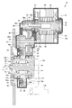
- FIG. 1 is a longitudinal sectional view showing an in-wheel motor drive device according to an embodiment of the present invention.
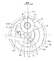
- FIG. 2 is a side view schematically showing the embodiment, and shows a state in the axial direction of the in-wheel motor drive device.
- the left side of the paper surface is the outside in the vehicle width direction
- the right side of the paper surface is the inside in the vehicle width direction.
- the upper side of the page is the upper side of the vehicle
- the lower side of the page is the lower side of the vehicle.
- the in-wheel motor drive device 10 includes a wheel hub bearing portion 11 provided at the center of a wheel (not shown), a motor portion 21 that drives the wheel, and a speed reduction portion that decelerates the rotation of the motor portion and transmits it to the wheel hub bearing portion 11. 31 is provided.
- the motor unit 21 and the speed reduction unit 31 are arranged offset from the axis O of the wheel hub bearing unit 11.
- the axis O extends in the vehicle width direction.
- the wheel hub bearing portion 11 is a rotating outer ring / fixed inner ring, and includes an outer ring 12 as a wheel hub coupled to a wheel wheel (not shown), and an inner fixing member 13 disposed on the inner periphery of the outer ring 12. And a plurality of rolling elements 14 disposed in an annular gap between the outer ring 12 and the inner fixing member 13.
- the inner fixing member 13 includes a non-rotating fixing shaft 15, an inner race 16, and a retaining nut 17.
- the fixed shaft 15 extends along the axis O direction, is formed with a small diameter on one side in the axis O direction, and is formed with a large diameter on the other side in the axis O direction.
- the other side of the fixed shaft 15 in the axis O direction is attached to the carrier 101 so as to be directed inward in the vehicle width direction.
- One of the fixed shafts 15 in the direction of the axis O is directed outward in the vehicle width direction, and an annular inner race 16 is fitted to the outer periphery.
- a retaining nut 17 is screwed to one end of the fixed shaft 15 in the axis O direction, and the inner race 16 is prevented from coming off.
- one side in the axis O direction means the outside in the vehicle width direction
- the other in the axis O direction means the inside in the vehicle width direction.
- the carrier 101 is connected to the suspension member 116.
- the rolling elements 14 are arranged in double rows with a separation in the direction of the axis O.
- the outer diameter surface of the inner race 16 constitutes an inner raceway surface of the rolling elements 14 in the first row and faces one inner diameter surface of the outer ring 12 in the axis O direction.
- the outer periphery of the central portion in the direction of the axis O of the fixed shaft 15 constitutes the inner raceway surface of the rolling elements 14 in the second row and faces the other inner diameter surface of the outer ring 12 in the direction of the axis O.
- a connecting portion 12 f is formed at one end of the outer ring 12 in the axis O direction.
- the coupling portion 12f is a flange and constitutes a coupling portion for coupling coaxially with the brake rotor 102 and a wheel (not shown).
- the outer ring 12 is coupled to the wheel at the coupling portion 12f and rotates integrally with the wheel.
- the motor unit 21 includes a motor rotating shaft 22, a rotor 23, a stator 24, and a motor casing 25, and is sequentially arranged from the axis M of the motor unit 21 to the outer diameter side in this order.
- the motor unit 21 is an inner rotor, outer stator type radial gap motor, but may be of other types.
- the motor unit 21 may be an axial gap.
- the axis M that is the rotation center of the motor rotation shaft 22 and the rotor 23 extends in parallel with the axis O of the wheel hub bearing portion 11. That is, the motor unit 21 is disposed offset from the axis O of the wheel hub bearing unit 11. Moreover, the axial direction position of the motor part 21 overlaps with the inner side fixing member 13 of the wheel hub bearing part 11 as shown in FIG. Thereby, the axial direction dimension of the in-wheel motor drive device 10 can be shortened.
- Both ends of the motor rotating shaft 22 are rotatably supported by the motor casing 25 via rolling bearings 27 and 28.
- the motor casing 25 has a substantially cylindrical shape, is integrally coupled with the main body casing 38 at one end in the axis M direction, and is sealed at the other end in the axis M direction.
- the motor unit 21 drives the outer ring 12.
- the speed reduction unit 31 is a three-axis parallel shaft gear reducer, and includes an output gear 36 provided coaxially on the outer peripheral surface of the outer ring 12, an input gear 32 connected coaxially with the motor rotation shaft 22 of the motor unit 21, A plurality of intermediate gears 33, 35 that transmit rotation from the input gear 32 to the output gear 36, and a main body casing 38 that accommodates these gears.
- the input gear 32 is a small-diameter external gear, and is a large number of teeth formed on the outer periphery of one end portion in the axial direction of the shaft portion 32 s arranged along the axis M.
- the outer periphery of the other end portion in the axial direction of the shaft portion 32 s is inserted into a center hole formed at one end portion in the axial direction of the motor rotation shaft 22 and is fitted so as not to be relatively rotatable.
- the shaft portion 32 s is rotatably supported by the main body casing 38 via rolling bearings 32 m and 32 n on both ends of the input gear 32.
- the main body casing 38 covers the speed reduction part 31 and the wheel hub bearing part 11 so as to surround the axes O, M, and R extending in parallel with each other, and covers both sides of the speed reduction part 31 in the axial direction.
- the shaft portion 32 s constitutes an input shaft of the speed reduction portion 31.
- One end surface in the axial direction of the main body casing 38 faces the brake rotor 102.
- the other end surface in the axial direction of the main body casing 38 is coupled to the motor casing 25.
- the motor casing 25 is attached to the main body casing 38 and protrudes from the main body casing 38 to the other side in the axial direction.
- the main casing 38 accommodates all the rotating elements (shafts and gears) of the speed reducing unit 31.
- the main body casing 38 is connected to the suspension member 115 above the carrier 101. That is, the in-wheel motor drive device 10 is attached to the suspension device of the electric vehicle at two locations, the main body casing 38 and the carrier 101.
- the small-diameter input gear 32 meshes with the first intermediate gear 33 that becomes a large-diameter external gear.
- the intermediate gear 33 is coupled coaxially with a second intermediate gear 35 that becomes a small-diameter external gear by an intermediate shaft 34.
- Both end portions of the intermediate shaft 34 are rotatably supported by the main body casing 38 via rolling bearings 34m and 34n.
- the first intermediate gear 33 and the second intermediate gear 35 are disposed between the rolling bearing 34m and the rolling bearing 34n, and are adjacent to each other.
- the first intermediate gear 33 and the intermediate shaft 34 are integrally formed, and the second intermediate gear 35 is fitted on the outer periphery of the intermediate shaft 34 so as not to be relatively rotatable.
- the speed reduction part 31 is a parallel triaxial gear speed reducer having axes O, R, and M extending in parallel with each other.
- the output gear 36 is an external gear, and the outer ring 12 is fitted in the center hole of the output gear 36 so as not to be relatively rotatable. Such fitting is spline fitting or serration fitting.
- the tooth tip and the tooth bottom of the output gear 36 have a larger diameter than the outer peripheral surface of the outer ring 12.
- a cylindrical portion 36 c is formed at the center of the output gear 36. Both end portions of the cylindrical portion 36c protrude from both end surfaces of the output gear 36, and are rotatably supported by the main body casing 38 via rolling bearings 36m and 36n.
- the cylindrical portion 36 c fitted with the outer ring 12 constitutes the output shaft of the speed reducing portion 31.
- wheel 12 to penetrate is formed in the axial direction both ends of the main body casing 38, respectively. Sealing materials 37c and 37d for sealing an annular gap with the outer ring 12 are provided in each opening. For this reason, the outer ring 12 serving as a rotating body is covered with the main body casing 38 except for one end in the axis O direction. In other words, the wheel hub bearing portion 11 is accommodated in the main body casing 38 except for both ends.
- the main casing 38 is installed across three axes O, R, and M that are parallel to each other.
- the first intermediate gear 33, the second intermediate gear 35, and the intermediate shaft 34 are arranged on the outer diameter side of the outer ring 12.
- the first intermediate gear 33, the second intermediate gear 35, and the intermediate shaft 34 are arranged so as to overlap with the position of the outer ring 12 in the axis O direction.
- the entire first intermediate gear 33 and the entire second intermediate gear 35 are disposed on the outer diameter side with respect to the outer ring 12.
- the intermediate shaft 34 is elongated to separate the large-diameter first intermediate gear 33 from the small-diameter second intermediate gear 35, and the outer periphery of the first intermediate gear 33 is connected to the outer ring 12 in the direction of the axis O. You may arrange
- the output gear 36 is located closest to the axis O in the other direction from the axial position of the center of the rolling elements 14 arranged in the row on the one side in the axis O most. It arrange
- the outer ring 12 is stably supported by the double-row rolling elements 14 and 14 while the wheels are being driven.
- the wheel hub bearing portion 11 and the speed reduction portion 31 are disposed in a circle 103c having a diameter equal to the rim inner diameter of the wheel wheel coupled to the outer ring 12.
- the output gear 36 is disposed in the circle 103c.
- the motor unit 21 is disposed on the inner side in the vehicle width direction than the wheel and avoids interference with the wheel 104.
- the wheel 104 is a well-known one having a wheel wheel 105 and a tire 106 fitted to the outer periphery of the wheel wheel 105.
- the wheel 104 is coaxially coupled to the wheel hub bearing 11 and has a common axis O.
- the axis R of the deceleration unit 31 is disposed above the axis O.
- the axis M of the motor unit 21 is disposed above the axis R. Thereby, it becomes easy to ensure the clearance from the road surface to the speed reduction part 31 and the clearance from the road surface to the motor part 21.
- an oil reservoir 51 a suction oil passage 52, an oil pump 53, a discharge oil passage 54, an input shaft oil passage 55, a rotor oil passage 56, a through hole 57, and an intermediate shaft oil passage 58 are used as lubricating oil passages. And connect in this order.
- the oil reservoir 51 is an internal space of the main body casing 38 and occupies the lower part of the in-wheel motor drive device 10. The lubricating oil accumulated in the oil reservoir 51 scrapes and lubricates the outer periphery of the output gear 36.
- FIG. 3 is a view showing a state in which the oil pump 53 is taken out and viewed in the axial direction.
- the oil pump 53 is a trochoid pump having an outer rotor 53j and an inner rotor 53k.
- the outer rotor 53j is accommodated in a circular chamber 53h formed in the main body casing 38.
- the outer ring 12 (FIG. 1) is inserted into the center hole 53l of the inner rotor 53k, the inner peripheral surface of the inner rotor 53k engages with the outer peripheral surface of the outer ring 12, and both rotate integrally.
- the oil pump 53 is disposed between the coupling portion 12f and the output gear 36.
- the output gear 36 has an outer peripheral portion having a tooth tip and a tooth bottom formed thick in the direction of the axis O, and a radial intermediate portion connecting the central portion and the outer peripheral portion is formed thin in the direction of the axis O. And it forms so that an outer peripheral part may protrude to an axis line O direction rather than a radial direction intermediate part. Therefore, an annular recess 36d is formed on one end surface of the output gear 36 in the axis O direction.
- the oil pump 53 is provided in the recess 36d.
- the dimension of the wheel hub bearing 11 in the direction of the axis O does not increase.
- the inner rotor of the oil pump 53 is fitted to the center of the output gear 36, the inner rotor may be fitted to the outer periphery of the outer ring 12 as a modification (not shown).
- a suction oil passage 52 and a discharge oil passage 54 are formed inside the wall thickness on one side in the axial direction of the main body casing 38.
- the suction oil passage 52 extends in the vertical direction, is connected to the oil reservoir 51 at the lower end, and is connected to the suction port of the oil pump 53 at the upper end.
- the discharge oil passage 54 extends in the vertical direction and is connected to the discharge port of the oil pump 53 at the lower end, and the upper end is connected to one end in the axial direction of the input shaft oil passage 55.
- the input shaft oil passage 55 is a central hole of the shaft portion 32s and extends along the axis M.
- the other axial end of the input shaft oil passage 55 is connected to the inner diameter side end of the rotor oil passage 56.
- the rotor oil passage 56 extends in the outer diameter direction from the inside of the motor rotating shaft 22 to the rotor 23.
- the outer diameter side end of the rotor oil passage 56 faces the stator coil 24 c of the stator 24.
- the through-hole 57 is provided in the lower part of the motor unit 21 and penetrates the partition wall 25w that partitions the internal space of the motor casing 25 and the internal space of the main body casing 38.
- One of the through holes 57 is connected at the same height as the bottom surface inside the motor casing 25.
- the other of the through holes 57 faces the end of the intermediate shaft oil passage 58.
- the intermediate shaft oil passage 58 is formed in the intermediate shaft 34 and extends along the axis R.
- the lubricating oil is drawn into the oil pump 53 from the oil reservoir 51 through the suction oil passage 52.
- the lubricating oil is discharged from the oil pump 53 and supplied to the motor unit 21 through the discharge oil passage 54 and the input shaft oil passage 55.
- the lubricating oil accumulated in the oil reservoir 51 and the lubricating oil flowing through the suction oil passage 52 and the discharge oil passage 54 are cooled by the main body casing 38.
- the lubricating oil flows through the rotor oil passage 56 and is injected into the stator coil 24 c to cool the motor unit 21.
- the lubricating oil falls along the inner peripheral surface of the motor casing 25, is supplied to the speed reduction unit 31 through the through hole 57, lubricates each rotating element (shaft, gear, and rolling bearing), and The oil is stored in the lower part, that is, in the oil reservoir 51.
- the lubricating oil flows through the intermediate shaft oil passage 58 from the through hole 57, and then lubricates each rotating element (shaft, gear, and rolling bearing) and stores it in the oil reservoir 51.
- the lubricating oil is again sucked into the oil pump 53 and circulates inside the in-wheel motor drive device 10.
- the oil pump 53 since the oil pump 53 is arranged coaxially with the outer ring 12 and driven by the outer ring 12, the oil pump 53 can be driven at the same rotational speed (1500 rpm or less) as the wheels. Therefore, the oil pump 53 is rotated at a low speed, there is no problem of vibration, and durability is improved.
- the output gear 36 is provided coaxially on the outer peripheral surface of the outer ring 12, so that the speed reduction part 31 is arranged offset from the wheel hub bearing part 11 to provide a multistage multi-axis parallel shaft type gear reduction gear. can do. Therefore, the motor unit 21 can be increased in speed and reduced in size and weight, and the in-wheel motor drive device 10 can be reduced in size and weight.
- the oil pump 53 since the oil pump 53 is attached to the outer periphery of the outer ring 12, the axial direction position of the oil pump 53 can be disposed so as to overlap the wheel hub bearing portion 11. Accordingly, the axial dimension of the wheel hub bearing portion 11 does not increase, and the entire wheel hub bearing portion 11 can be accommodated in the inner space of the wheel.
- the outer ring 12 has the coupling portion 12f for coupling with the wheel on one side in the axis O direction, and the oil pump 53 is disposed between the coupling portion 12f and the output gear 36.
- the space between the coupling portion 12f and the output gear 36 can be used effectively.
- the oil pump 53 includes the outer rotor 53j and the inner rotor 53k (FIG. 3), and the inner peripheral surface of the center hole 53l of the inner rotor 53k is engaged with the outer peripheral surface of the outer ring 12. Accordingly, a trochoid pump, a cycloid pump, or an involute gear pump can be used as the oil pump 53.
- the annular recess 36d is formed coaxially on the end face on the one side in the axis O direction of the output gear 36, and the oil pump 53 is provided in the recess 36d. Even if the oil pump 53 is provided, the dimension of the wheel hub bearing 11 in the direction of the axis O does not increase.
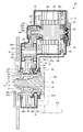
- FIG. 4 is a longitudinal sectional view showing another embodiment of the present invention.
- the same reference numerals are given to the configurations common to the above-described embodiments, and the description thereof will be omitted, and different configurations will be described below.
- the oil pump 53 is disposed on the other side in the axis O direction that is opposite to the coupling portion 12 f when viewed from the output gear 36. Since the first intermediate gear 33 is disposed on the outer diameter side of the outer ring 12 and overlaps with the axial position of the outer ring 12, a space is defined between the first intermediate gear 33 and the outer ring 12. An oil pump 53 is disposed in this space.
- a spline groove 12s having a constant outer diameter is formed from one side in the axial direction to the other side.
- the spline groove 12s is fitted with a spline groove formed on the inner peripheral surface of the output gear 36 on one side in the axial direction, and a spline groove formed on the inner peripheral surface of the center hole 53l of the inner rotor 53k on the other side in the axial direction. Mating.
- the lubricating oil circuit of another embodiment has a stator oil passage 59 instead of the rotor oil passage described above.
- the stator oil passage 59 is a pipe line installed in the motor casing 25 and extending annularly along the end surface of the stator 24.
- the stator oil passage 59 is connected to the upper end of the discharge oil passage 54.
- a plurality of nozzles 59n directed to the end face of the stator 24 are provided at intervals.
- Lubricating oil supplied to the motor unit 21 from the discharge oil passage 54 is injected from the nozzle 59 n to the stator 24 to cool the stator 24.
- the lubricating oil falls along the inner peripheral surface of the motor casing 25, is discharged from the through hole 57, and is supplied from the motor unit 21 to the speed reduction unit 31.
- a protrusion 22p is formed at one end of the motor rotating shaft 22 in the axis O direction.
- the protrusion 22p extends along the axis M and is inserted into the center hole of the shaft 32s.
- the input gear 32 is coupled coaxially with the motor rotation shaft 22.
- the outer ring 12 has a coupling portion 12f for coupling to the wheel on one side in the axis O direction
- the oil pump 53 is an axis O that is opposite to the coupling portion 12f when viewed from the output gear 36. It is arranged on the other side in the direction.
- the space between the first intermediate gear 33 and the outer ring 12 can be used effectively.
- the axial position of the first intermediate gear 33 can be overlapped with the oil pump 53, and the axial dimension of the in-wheel motor drive device 20 can be reduced.
- an annular step is not provided on the outer periphery of the outer ring 12, and the output gear 36 and the inner rotor 53k can be fitted to the outer ring 12 using the common spline groove 12s, so that the assembly efficiency is improved. To do. Further, since the inner rotor 53k is fitted to the outer ring 12, it is not necessary to make the outer ring 12 thin and have a small diameter, and the strength of the outer ring 12 can be prevented from being lowered.
- FIG. 5 is a longitudinal sectional view showing an in-wheel motor drive device 30 according to still another embodiment of the present invention. Further, regarding the other embodiments, the same reference numerals are given to configurations common to the above-described embodiments, description thereof is omitted, and different configurations will be described below.
- the oil pump 53 is attached to the outer wall surface of the main body casing 38.
- the wheel hub bearing portion 11 is a rotating inner ring / fixed outer ring
- the reduction portion 31 is a four-axis parallel shaft gear reducer further having an intermediate shaft 42. is there.
- the wheel hub bearing portion 11 includes an inner ring 46 that is a rotating element, an outer ring 47 that is a fixed element, and a plurality of rolling elements 48 that are arranged in an annular gap between the inner and outer rings.
- a flange is erected on the outer peripheral surface of the outer ring 47.
- a through hole is formed in the outer ring flange with a gap in the circumferential direction.
- Each through-hole extends in parallel with the axis O, and a bolt 47b is passed from one side in the direction of the axis O.
- the shaft portion of each bolt 47 b is screwed into a female screw hole formed in the front portion 38 f of the main body casing 38.
- the outer ring 47 is connected and fixed to the front portion 38f.
- the front portion 38 f is a casing wall portion that covers one end of the speed reduction portion 31 in the axis O direction.
- the back surface portion 38 b is a casing wall portion that covers the other end of the speed reduction portion 31 in the axis O direction.
- the inner ring 46 is a cylindrical body longer than the outer ring 47, and is passed through the center hole of the outer ring 47.
- a coupling portion 46f is formed at one end of the inner ring 46 protruding from the outer ring 47 to the outside of the in-wheel motor drive device 30 in the axis O direction.
- the coupling portion 46f is a flange, and constitutes a coupling portion for coupling coaxially with a brake rotor and a wheel (not shown).
- the inner ring 46 is coupled to the wheel at the coupling portion 46f and rotates integrally with the wheel.
- a plurality of rows of rolling elements 48 are arranged in the annular gap between the inner ring 46 and the outer ring 47.
- One outer peripheral surface of the inner ring 46 in the direction of the axis O constitutes an inner race of the rolling elements 48 in the first row.
- An inner raceway 46r is fitted to the outer circumference of the other end of the inner ring 46 in the axis O direction, and the outer circumferential surface of the inner raceway 46r constitutes the inner raceway of the rolling elements 48 in the second row.
- a seal material 49 is further interposed in the annular gap between the inner ring 46 and the outer ring 47. The sealing material 49 seals both ends of the annular gap to prevent entry of dust and foreign matter.
- the output shaft 45 of the speed reduction part 31 is inserted into the center hole at the other end in the axis O direction of the inner ring 46 and is splined.
- the intermediate shaft 42 of the speed reduction portion 31 extends in parallel with the axis O, and both ends of the intermediate shaft 42 are rotatably supported by the front portion 38f and the back portion 38b of the main body casing 38 via bearings 42m and 42n.
- a third intermediate gear 41 and a fourth intermediate gear 43 are provided coaxially at the center of the intermediate shaft 42.
- the third intermediate gear 41 and the fourth intermediate gear 43 are external helical gears, and the diameter of the third intermediate gear 41 is larger than the diameter of the fourth intermediate gear 43.
- the relatively small-diameter second intermediate gear 35 meshes with the relatively large-diameter third intermediate gear 41.
- the relatively small fourth intermediate gear 43 meshes with the relatively large diameter output gear 44.
- the output gear 44 is an external gear provided coaxially with the output shaft 45, and is a helical gear.
- the output shaft 45 is rotatably supported by the front portion 38f of the main body casing 38 via the rolling bearing 45m on the one side in the axis O direction than the output gear 44. Further, the output shaft 45 is rotatably supported on the back surface portion 38b of the main body casing 38 via a rolling bearing 45n on the other side in the axis O direction than the output gear 44.
- the other end of the output shaft 45 in the direction of the axis O extends through the back surface portion 38 b and is coupled to the oil pump 53.
- the oil pump 53 is attached to the outer wall surface of the back surface portion 38b and protrudes from the outer wall surface of the back surface portion 38b.
- the oil pump 53 is arranged coaxially with the axis O of the wheel hub bearing 11 and is driven by the output shaft 45. In the embodiment shown in FIG. Thereby, the oil pump 53 can be driven at the same rotational speed as the wheels. Therefore, the oil pump 53 is rotated at a low speed, there is no problem of vibration, and durability is improved.
- the fixed wheel is the outer ring 47
- the rotating wheel is the inner ring 46 disposed in the center hole of the outer ring 47.
- the present invention can also be realized by the wheel hub bearing portion 11 of the outer ring rotation / inner ring fixing shown in FIGS. 1 and 4 or the wheel hub bearing portion 11 of the inner ring rotation / outer ring fixing shown in FIG.
- the oil pump 53 is coupled to the end of the output shaft 45.
- the oil pump 53 can be disposed adjacent to the elongated output shaft 45. Therefore, the degree of freedom in the layout of the oil pump 53 is improved, and for example, the oil pump 53 can be provided so as to protrude from the back surface portion 38 b of the casing 38.
- the outer diameter dimension of the oil pump 53 can be made closer to the outer diameter dimension of the output shaft 45 so that it can be made smaller than the conventional one.
- the oil pump may be engaged with the outer peripheral surface of the output shaft 45 as a modification (not shown).
- the in-wheel motor drive device according to the present invention is advantageously used in electric vehicles and hybrid vehicles.
Landscapes
- Engineering & Computer Science (AREA)
- General Engineering & Computer Science (AREA)
- Mechanical Engineering (AREA)
- Chemical & Material Sciences (AREA)
- Combustion & Propulsion (AREA)
- Transportation (AREA)
- Arrangement Or Mounting Of Propulsion Units For Vehicles (AREA)
Abstract
L'invention concerne un dispositif d'entraînement de moteur-roue (10) comprenant: une partie de roulement de moyeu de roue (11) comprenant une roue rotative (12) qui tourne d'un seul tenant avec une roue, une roue fixe (13) disposée de manière coaxiale avec la roue rotative et une pluralité d'éléments roulants (14) disposés dans un espace annulaire entre la roue rotative et la roue fixe; une unité de moteur (21) permettant d'entraîner la roue rotative; un arbre de sortie (36c) accouplé de manière coaxiale à la roue rotative; et un engrenage d'entrée (32) accouplé à un arbre de rotation de moteur (22) de l'unité de moteur. Ce dispositif d'entraînement de moteur-roue (10) comprend: une unité de décélération (31) permettant de décélérer et de transmettre à la roue rotative la rotation de l'arbre de rotation de moteur (22); et une pompe à huile (53) disposée de manière coaxiale avec la partie de roulement de moyeu de roue et entraînée par l'arbre de sortie.
Priority Applications (3)
| Application Number | Priority Date | Filing Date | Title |
|---|---|---|---|
| US15/763,494 US20180294692A1 (en) | 2015-09-30 | 2016-09-29 | In-wheel motor driving device |
| EP16851747.2A EP3357731A4 (fr) | 2015-09-30 | 2016-09-29 | Dispositif d'entraînement de moteur-roue |
| CN201680043458.2A CN107848398A (zh) | 2015-09-30 | 2016-09-29 | 轮内电动机驱动装置 |
Applications Claiming Priority (4)
| Application Number | Priority Date | Filing Date | Title |
|---|---|---|---|
| JP2015193386 | 2015-09-30 | ||
| JP2015-193386 | 2015-09-30 | ||
| JP2016-188289 | 2016-09-27 | ||
| JP2016188289A JP2017065671A (ja) | 2015-09-30 | 2016-09-27 | インホイールモータ駆動装置 |
Publications (1)
| Publication Number | Publication Date |
|---|---|
| WO2017057576A1 true WO2017057576A1 (fr) | 2017-04-06 |
Family
ID=58423592
Family Applications (1)
| Application Number | Title | Priority Date | Filing Date |
|---|---|---|---|
| PCT/JP2016/078826 Ceased WO2017057576A1 (fr) | 2015-09-30 | 2016-09-29 | Dispositif d'entraînement de moteur-roue |
Country Status (1)
| Country | Link |
|---|---|
| WO (1) | WO2017057576A1 (fr) |
Citations (3)
| Publication number | Priority date | Publication date | Assignee | Title |
|---|---|---|---|---|
| JP2009226973A (ja) * | 2008-03-19 | 2009-10-08 | Aisin Seiki Co Ltd | インホイールモータシステム |
| JP2010111362A (ja) * | 2008-11-10 | 2010-05-20 | Toyota Motor Corp | インホイールモータ冷却構造 |
| JP2013181645A (ja) * | 2012-03-05 | 2013-09-12 | Ntn Corp | 電気自動車用駆動装置 |
-
2016
- 2016-09-29 WO PCT/JP2016/078826 patent/WO2017057576A1/fr not_active Ceased
Patent Citations (3)
| Publication number | Priority date | Publication date | Assignee | Title |
|---|---|---|---|---|
| JP2009226973A (ja) * | 2008-03-19 | 2009-10-08 | Aisin Seiki Co Ltd | インホイールモータシステム |
| JP2010111362A (ja) * | 2008-11-10 | 2010-05-20 | Toyota Motor Corp | インホイールモータ冷却構造 |
| JP2013181645A (ja) * | 2012-03-05 | 2013-09-12 | Ntn Corp | 電気自動車用駆動装置 |
Non-Patent Citations (1)
| Title |
|---|
| See also references of EP3357731A4 * |
Similar Documents
| Publication | Publication Date | Title |
|---|---|---|
| JP2017065671A (ja) | インホイールモータ駆動装置 | |
| US8245803B2 (en) | Wheel assembly with in-wheel motor | |
| US8932166B2 (en) | Drive device for electric vehicle | |
| CN103328247B (zh) | 轮毂电机驱动装置 | |
| US9705378B2 (en) | Drive device for electric vehicle | |
| US9333843B2 (en) | Drive device for electric vehicle | |
| JP5066925B2 (ja) | 車輪駆動装置 | |
| JP6508148B2 (ja) | インホイールモータユニット | |
| JP2009012523A (ja) | 車輪駆動装置 | |
| US9735648B2 (en) | Drive device for electric vehicle | |
| CN102648362A (zh) | 轮毂电机驱动装置 | |
| WO2012111412A1 (fr) | Appareil d'entraînement d'un moteur-roue | |
| JP2012034481A (ja) | 車両用モータ駆動装置 | |
| JP2013181645A (ja) | 電気自動車用駆動装置 | |
| WO2018073976A1 (fr) | Dispositif d'entraînement de moteur-roue | |
| JP2017214014A (ja) | インホイールモータ駆動装置 | |
| JP2017159883A (ja) | インホイールモータ駆動装置 | |
| CN108292880A (zh) | 轮内电动机驱动装置 | |
| CN110271407A (zh) | 轮内电动机驱动装置 | |
| WO2021095678A1 (fr) | Dispositif d'entraînement de moteur-roue | |
| JP6843511B2 (ja) | インホイールモータ駆動装置 | |
| WO2017057576A1 (fr) | Dispositif d'entraînement de moteur-roue | |
| CN110154744A (zh) | 轮内电动机驱动装置 | |
| JP2016151321A (ja) | インホイールモータ駆動装置 | |
| JP6581453B2 (ja) | インホイールモータ駆動装置 |
Legal Events
| Date | Code | Title | Description |
|---|---|---|---|
| 121 | Ep: the epo has been informed by wipo that ep was designated in this application |
Ref document number: 16851747 Country of ref document: EP Kind code of ref document: A1 |
|
| WWE | Wipo information: entry into national phase |
Ref document number: 15763494 Country of ref document: US |
|
| NENP | Non-entry into the national phase |
Ref country code: DE |