WO2017061167A1 - 多段圧縮機およびこれを備えた冷凍システム - Google Patents
多段圧縮機およびこれを備えた冷凍システム Download PDFInfo
- Publication number
- WO2017061167A1 WO2017061167A1 PCT/JP2016/072994 JP2016072994W WO2017061167A1 WO 2017061167 A1 WO2017061167 A1 WO 2017061167A1 JP 2016072994 W JP2016072994 W JP 2016072994W WO 2017061167 A1 WO2017061167 A1 WO 2017061167A1
- Authority
- WO
- WIPO (PCT)
- Prior art keywords
- refrigerant
- housing
- electric motor
- compression mechanism
- injection nozzle
- Prior art date
- Legal status (The legal status is an assumption and is not a legal conclusion. Google has not performed a legal analysis and makes no representation as to the accuracy of the status listed.)
- Ceased
Links
Images


Classifications
-
- F—MECHANICAL ENGINEERING; LIGHTING; HEATING; WEAPONS; BLASTING
- F04—POSITIVE - DISPLACEMENT MACHINES FOR LIQUIDS; PUMPS FOR LIQUIDS OR ELASTIC FLUIDS
- F04C—ROTARY-PISTON, OR OSCILLATING-PISTON, POSITIVE-DISPLACEMENT MACHINES FOR LIQUIDS; ROTARY-PISTON, OR OSCILLATING-PISTON, POSITIVE-DISPLACEMENT PUMPS
- F04C23/00—Combinations of two or more pumps, each being of rotary-piston or oscillating-piston type, specially adapted for elastic fluids; Pumping installations specially adapted for elastic fluids; Multi-stage pumps specially adapted for elastic fluids
- F04C23/001—Combinations of two or more pumps, each being of rotary-piston or oscillating-piston type, specially adapted for elastic fluids; Pumping installations specially adapted for elastic fluids; Multi-stage pumps specially adapted for elastic fluids of similar working principle
-
- F—MECHANICAL ENGINEERING; LIGHTING; HEATING; WEAPONS; BLASTING
- F04—POSITIVE - DISPLACEMENT MACHINES FOR LIQUIDS; PUMPS FOR LIQUIDS OR ELASTIC FLUIDS
- F04B—POSITIVE-DISPLACEMENT MACHINES FOR LIQUIDS; PUMPS
- F04B39/00—Component parts, details, or accessories, of pumps or pumping systems specially adapted for elastic fluids, not otherwise provided for in, or of interest apart from, groups F04B25/00 - F04B37/00
- F04B39/06—Cooling; Heating; Prevention of freezing
-
- F—MECHANICAL ENGINEERING; LIGHTING; HEATING; WEAPONS; BLASTING
- F04—POSITIVE - DISPLACEMENT MACHINES FOR LIQUIDS; PUMPS FOR LIQUIDS OR ELASTIC FLUIDS
- F04C—ROTARY-PISTON, OR OSCILLATING-PISTON, POSITIVE-DISPLACEMENT MACHINES FOR LIQUIDS; ROTARY-PISTON, OR OSCILLATING-PISTON, POSITIVE-DISPLACEMENT PUMPS
- F04C23/00—Combinations of two or more pumps, each being of rotary-piston or oscillating-piston type, specially adapted for elastic fluids; Pumping installations specially adapted for elastic fluids; Multi-stage pumps specially adapted for elastic fluids
- F04C23/005—Combinations of two or more pumps, each being of rotary-piston or oscillating-piston type, specially adapted for elastic fluids; Pumping installations specially adapted for elastic fluids; Multi-stage pumps specially adapted for elastic fluids of dissimilar working principle
-
- F—MECHANICAL ENGINEERING; LIGHTING; HEATING; WEAPONS; BLASTING
- F04—POSITIVE - DISPLACEMENT MACHINES FOR LIQUIDS; PUMPS FOR LIQUIDS OR ELASTIC FLUIDS
- F04C—ROTARY-PISTON, OR OSCILLATING-PISTON, POSITIVE-DISPLACEMENT MACHINES FOR LIQUIDS; ROTARY-PISTON, OR OSCILLATING-PISTON, POSITIVE-DISPLACEMENT PUMPS
- F04C23/00—Combinations of two or more pumps, each being of rotary-piston or oscillating-piston type, specially adapted for elastic fluids; Pumping installations specially adapted for elastic fluids; Multi-stage pumps specially adapted for elastic fluids
- F04C23/008—Hermetic pumps
-
- F—MECHANICAL ENGINEERING; LIGHTING; HEATING; WEAPONS; BLASTING
- F04—POSITIVE - DISPLACEMENT MACHINES FOR LIQUIDS; PUMPS FOR LIQUIDS OR ELASTIC FLUIDS
- F04C—ROTARY-PISTON, OR OSCILLATING-PISTON, POSITIVE-DISPLACEMENT MACHINES FOR LIQUIDS; ROTARY-PISTON, OR OSCILLATING-PISTON, POSITIVE-DISPLACEMENT PUMPS
- F04C29/00—Component parts, details or accessories of pumps or pumping installations, not provided for in groups F04C18/00 - F04C28/00
- F04C29/04—Heating; Cooling; Heat insulation
- F04C29/042—Heating; Cooling; Heat insulation by injecting a fluid
-
- F—MECHANICAL ENGINEERING; LIGHTING; HEATING; WEAPONS; BLASTING
- F04—POSITIVE - DISPLACEMENT MACHINES FOR LIQUIDS; PUMPS FOR LIQUIDS OR ELASTIC FLUIDS
- F04C—ROTARY-PISTON, OR OSCILLATING-PISTON, POSITIVE-DISPLACEMENT MACHINES FOR LIQUIDS; ROTARY-PISTON, OR OSCILLATING-PISTON, POSITIVE-DISPLACEMENT PUMPS
- F04C29/00—Component parts, details or accessories of pumps or pumping installations, not provided for in groups F04C18/00 - F04C28/00
- F04C29/04—Heating; Cooling; Heat insulation
- F04C29/045—Heating; Cooling; Heat insulation of the electric motor in hermetic pumps
-
- F—MECHANICAL ENGINEERING; LIGHTING; HEATING; WEAPONS; BLASTING
- F25—REFRIGERATION OR COOLING; COMBINED HEATING AND REFRIGERATION SYSTEMS; HEAT PUMP SYSTEMS; MANUFACTURE OR STORAGE OF ICE; LIQUEFACTION SOLIDIFICATION OF GASES
- F25B—REFRIGERATION MACHINES, PLANTS OR SYSTEMS; COMBINED HEATING AND REFRIGERATION SYSTEMS; HEAT PUMP SYSTEMS
- F25B1/00—Compression machines, plants or systems with non-reversible cycle
-
- F—MECHANICAL ENGINEERING; LIGHTING; HEATING; WEAPONS; BLASTING
- F25—REFRIGERATION OR COOLING; COMBINED HEATING AND REFRIGERATION SYSTEMS; HEAT PUMP SYSTEMS; MANUFACTURE OR STORAGE OF ICE; LIQUEFACTION SOLIDIFICATION OF GASES
- F25B—REFRIGERATION MACHINES, PLANTS OR SYSTEMS; COMBINED HEATING AND REFRIGERATION SYSTEMS; HEAT PUMP SYSTEMS
- F25B1/00—Compression machines, plants or systems with non-reversible cycle
- F25B1/10—Compression machines, plants or systems with non-reversible cycle with multi-stage compression
-
- F—MECHANICAL ENGINEERING; LIGHTING; HEATING; WEAPONS; BLASTING
- F04—POSITIVE - DISPLACEMENT MACHINES FOR LIQUIDS; PUMPS FOR LIQUIDS OR ELASTIC FLUIDS
- F04C—ROTARY-PISTON, OR OSCILLATING-PISTON, POSITIVE-DISPLACEMENT MACHINES FOR LIQUIDS; ROTARY-PISTON, OR OSCILLATING-PISTON, POSITIVE-DISPLACEMENT PUMPS
- F04C18/00—Rotary-piston pumps specially adapted for elastic fluids
- F04C18/02—Rotary-piston pumps specially adapted for elastic fluids of arcuate-engagement type, i.e. with circular translatory movement of co-operating members, each member having the same number of teeth or tooth-equivalents
- F04C18/0207—Rotary-piston pumps specially adapted for elastic fluids of arcuate-engagement type, i.e. with circular translatory movement of co-operating members, each member having the same number of teeth or tooth-equivalents both members having co-operating elements in spiral form
- F04C18/0215—Rotary-piston pumps specially adapted for elastic fluids of arcuate-engagement type, i.e. with circular translatory movement of co-operating members, each member having the same number of teeth or tooth-equivalents both members having co-operating elements in spiral form where only one member is moving
-
- F—MECHANICAL ENGINEERING; LIGHTING; HEATING; WEAPONS; BLASTING
- F04—POSITIVE - DISPLACEMENT MACHINES FOR LIQUIDS; PUMPS FOR LIQUIDS OR ELASTIC FLUIDS
- F04C—ROTARY-PISTON, OR OSCILLATING-PISTON, POSITIVE-DISPLACEMENT MACHINES FOR LIQUIDS; ROTARY-PISTON, OR OSCILLATING-PISTON, POSITIVE-DISPLACEMENT PUMPS
- F04C18/00—Rotary-piston pumps specially adapted for elastic fluids
- F04C18/30—Rotary-piston pumps specially adapted for elastic fluids having the characteristics covered by two or more of groups F04C18/02, F04C18/08, F04C18/22, F04C18/24, F04C18/48, or having the characteristics covered by one of these groups together with some other type of movement between co-operating members
- F04C18/34—Rotary-piston pumps specially adapted for elastic fluids having the characteristics covered by two or more of groups F04C18/02, F04C18/08, F04C18/22, F04C18/24, F04C18/48, or having the characteristics covered by one of these groups together with some other type of movement between co-operating members having the movement defined in group F04C18/08 or F04C18/22 and relative reciprocation between the co-operating members
- F04C18/356—Rotary-piston pumps specially adapted for elastic fluids having the characteristics covered by two or more of groups F04C18/02, F04C18/08, F04C18/22, F04C18/24, F04C18/48, or having the characteristics covered by one of these groups together with some other type of movement between co-operating members having the movement defined in group F04C18/08 or F04C18/22 and relative reciprocation between the co-operating members with vanes reciprocating with respect to the outer member
-
- F—MECHANICAL ENGINEERING; LIGHTING; HEATING; WEAPONS; BLASTING
- F04—POSITIVE - DISPLACEMENT MACHINES FOR LIQUIDS; PUMPS FOR LIQUIDS OR ELASTIC FLUIDS
- F04C—ROTARY-PISTON, OR OSCILLATING-PISTON, POSITIVE-DISPLACEMENT MACHINES FOR LIQUIDS; ROTARY-PISTON, OR OSCILLATING-PISTON, POSITIVE-DISPLACEMENT PUMPS
- F04C2270/00—Control; Monitoring or safety arrangements
- F04C2270/19—Temperature
- F04C2270/195—Controlled or regulated
Definitions
- the present invention relates to a multistage compressor and a refrigeration system provided with the same.
- a compressor for compressing gas refrigerant in an air conditioner or refrigeration apparatus As a compressor for compressing gas refrigerant in an air conditioner or refrigeration apparatus, a low-stage compression mechanism, a high-stage compression mechanism, and an electric motor for driving these compressors are provided in a housing formed in a closed container shape.
- a multi-stage compressor in which is housed.
- an electric motor is installed at an axial center in a substantially cylindrical housing, and the electric motor is driven by a main shaft driven by the electric motor.
- the lower stage side compression mechanism installed in the lower part of the above and the higher stage side compression mechanism installed in the upper part of the electric motor are coaxially driven.
- the multi-stage compressor described in Patent Document 1 includes an injection circuit which injects a gas refrigerant at an intermediate pressure extracted from the refrigerant circuit into the housing as an injection refrigerant.
- the injection circuit communicates with a first circuit connected in communication with the electric motor on the same side of the housing space on the same side as the high-stage side compression mechanism and a housing internal space on the opposite side of the high-stage side compression mechanism with the electric motor interposed. It comprises a second circuit connected and a switching mechanism for selectively communicating the first circuit and the second circuit into the housing according to the dryness of the injected refrigerant.
- the switching mechanism switches the injection circuit to the first circuit when the dryness of the injection refrigerant is equal to or higher than the set value, and the injection refrigerant having a high degree of thirst from the opening of the first circuit, that is, the dried refrigerant is contained inside the housing. Inject.
- the gas refrigerant of intermediate pressure is supplied to the high stage side compression mechanism, and the reduction of the suction efficiency of the high stage side compression mechanism is prevented to enhance the compression efficiency. be able to.
- the switching mechanism switches the injection circuit to the second circuit when the dryness of the injection refrigerant is less than the set value, and the injection circuit with low thirst from the opening of the second circuit, that is, the moist refrigerant is contained inside the housing Inject.
- the moist injection refrigerant passes through the vicinity of the electric motor, is heated by the operation heat of the electric motor, and the liquid is vaporized to be a dried gas refrigerant and sucked into the high-stage compression mechanism. This eliminates the possibility of liquid compression in the high-stage compression mechanism.
- the multi-stage compressor of Patent Document 1 detects the dryness of the injection refrigerant, and when the dryness is lower than a predetermined value, the injection refrigerant is allowed to pass through the electric motor so as to pass through the electric motor.
- the operation heat is used to dry the injection refrigerant, thereby preventing the liquid refrigerant from being sucked into the high-stage compression mechanism.
- the coil temperature rises under the operating condition where the circulating amount of the refrigerant decreases or the motor efficiency decreases, and the operation has to be stopped for safety when reaching the specified upper limit temperature.
- the injection refrigerant when the injection refrigerant is injected into the housing from the first circuit, the injection refrigerant does not pass through the electric motor, and thus the electric motor operates as described above at this timing. Overheating may limit the operable range.
- the present invention has been made in view of such circumstances, and after improving the system efficiency by injection, while preventing liquid compression in the high stage side compression mechanism, the injection refrigerant always keeps the electric motor effective. It is an object of the present invention to provide a multistage compressor which can be cooled to expand its operable range and a refrigeration system provided with the same.
- the multi-stage compressor according to the present invention comprises a housing in the form of a closed container, a low stage compression mechanism and a high stage compression mechanism installed in the housing, and an intermediate pressure area in the housing.
- a refrigerant supply unit for extracting a part and a liquid phase and selectively supplying the extracted part as an injection refrigerant to the injection nozzle;
- the refrigerant supply portion selectively supplies the gas phase component and the liquid phase component of the compressed refrigerant discharged from the high stage side compression mechanism to the injection nozzle, and the injection nozzle to the electric motor It is injected. That is, the gas refrigerant or the liquid refrigerant can be selectively injected to the electric motor. Alternatively, the gas refrigerant and the liquid refrigerant can be mixed and injected to the electric motor.
- the electric motor can be always cooled effectively by the injection refrigerant, and the operable range can be expanded.
- the refrigerant supply unit is a first refrigerant supply passage that is branched from a condensing refrigerant passage through which the compressed refrigerant discharged from the high stage side compression mechanism and condensed and cooled flows and is connected to the injection nozzle
- a second refrigerant supply passage extending from a liquid surface space of a gas-liquid separator for gas-liquid separation of the compressed refrigerant discharged from the high stage side compression mechanism and connected to the injection nozzle; and the first refrigerant supply passage
- the on-off valve may be opened when the operating temperature of the electric motor reaches a predetermined threshold temperature.
- the control unit closes the on-off valve until the operating temperature of the electric motor reaches the predetermined threshold temperature, and the gas phase of the compressed refrigerant separated by the gas-liquid separator, ie, the gas refrigerant Only the second refrigerant supply passage is supplied from the injection nozzle to the electric motor. Thereby, cooling by injection of only the gas refrigerant that improves the efficiency of the refrigeration system is performed.
- the control unit opens the on-off valve, and the condensed refrigerant including the liquid phase is supplied from the injection nozzle to the electric motor through the first refrigerant supply passage. Thereby, the cooling by the injection of the liquid refrigerant or the gas-liquid mixed refrigerant having a high cooling effect of the electric motor is performed.
- the temperature detection unit may be a refrigerant temperature sensor that detects the temperature of the compressed refrigerant discharged from the high stage side compression mechanism.
- the operating temperature of the electric motor can be easily detected based on the temperature of the compressed refrigerant detected by the refrigerant temperature sensor.
- the position of the inner opening of the injection nozzle inside the housing may be near the end of the electric motor that is upstream in the flow direction of the refrigerant in the housing.
- the injection refrigerant injected from the injection nozzle to the end of the electric motor rides on the flow of the intermediate pressure refrigerant flowing inside the housing and flows toward the opposite end of the electric motor. Therefore, the electric motor can be cooled uniformly.
- the liquid refrigerant When the liquid refrigerant is injected from the injection nozzle, the liquid refrigerant flows along the axial direction of the electric motor and is vaporized by the operation heat of the electric motor. Therefore, it is possible to prevent the liquid refrigerant that is not vaporized from being sucked into the high pressure side compression mechanism installed downstream of the electric motor and being liquid-compressed, and the soundness of the high pressure side compression mechanism can be maintained. .
- the position of the inner opening of the injection nozzle on the inner side of the housing may be near the lower portion of the electric motor inside the housing.
- the liquid refrigerant when the liquid refrigerant is injected from the injection nozzle, the liquid refrigerant tends to stay around the electric motor by gravity, so that the liquid refrigerant is easily vaporized by the operation heat of the electric motor. it can. Therefore, there is no possibility that the liquid refrigerant is taken up by the rotation of the electric motor and sucked into the high-stage compression mechanism as it is, and the high-stage compression mechanism can prevent the liquid refrigerant from being compressed.
- the height of the inner opening of the injection nozzle on the inner side of the housing may be higher than the in-operation oil level of the lubricating oil injected into the housing.
- the height of the outer opening of the injection nozzle on the outer side of the housing may be higher than the stop oil level height of the lubricating oil injected into the housing.
- the circumferential position of the injection nozzle with respect to the housing is a position deviated from a position where lubricating oil flows downward from the upper portion to the lower portion in the housing in a plan view of the housing. Good.
- the lubricating oil flowing down from the upper portion in the housing during operation of the multistage compressor does not hit the flow of the injection refrigerant injected from the injection nozzle into the housing. Therefore, it is possible to prevent the lubricating oil from being blown up in the housing, and to prevent the sprayed lubricating oil from being sucked into the high-stage side compression mechanism as it is and discharged to the outside of the multistage compressor.
- a refrigeration system includes any one of the above-described multistage compressors.
- this refrigeration system according to the degree of temperature rise of the electric motor, cooling by injection of only the gas refrigerant that improves the efficiency of the refrigeration system is performed, or liquid refrigerant or gas-liquid mixed refrigerant with high electric motor cooling effect Can be cooled by the injection of For this reason, it is possible to always effectively cool the electric motor by the injection refrigerant and to expand the operable range.
- the injection efficiency is improved by the injection refrigerant while preventing the liquid compression in the high stage side compression mechanism after the system efficiency is improved by the injection.
- the electric motor can be always cooled effectively to expand the operable range.
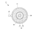
- FIG. 3 is a cross-sectional view of the multistage compressor taken along line III-III in FIG. It is a longitudinal cross-sectional view which shows another example of a shape of an injection nozzle.
- FIG. 1 is a schematic configuration diagram of a refrigeration system according to an embodiment of the present invention.
- the refrigeration system 1 is, for example, for a store showcase, but may be for other uses.
- a multistage compressor 2, a condenser 3, a gas-liquid separator 4, and an evaporator 5 are connected to the refrigerant passages 7a, 7b, 7c, 7d in this order to perform refrigeration / refrigeration operation Is configured to do.
- the refrigerant passages 7b and 7c are provided with expansion valves 8 and 9 for automatically adjusting the pressure and the flow rate of the refrigerant, respectively.
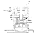
- FIG. 2 is a longitudinal sectional view of the multistage compressor 2.
- the multistage compressor 2 has a known basic structure. As shown in FIG. 1 and FIG. 2, the multistage compressor 2 includes a substantially cylindrical and sealed container-like housing 11 disposed with its axial direction oriented in the vertical direction.
- the electric motor 12 is installed in the central portion in the axial direction inside the housing 11, and the rotary compressor 13 (lower stage compression mechanism) is installed below the electric motor 12, that is, below the housing 11.
- the scroll compressor 14 (high stage side compression mechanism) is installed on the upper side, that is, on the upper part of the housing 11.
- the rotary compressor 13 and the scroll compressor 14 are coaxially driven by a main shaft 16 axially supported along the central axis of the housing 11.
- the electric motor 12 includes a stator 17 (stator) fixed to the inner peripheral surface of the housing 11 and a rotor 18 (rotor) positioned on the inner peripheral side of the stator 17 and integrally rotating with the main shaft 16 A coil 17 a is wound around the stator 17.
- stator 17 stator
- rotor 18 rotor
- cranks 16a and 16b eccentrically formed at both ends of the main shaft 16 are eccentrically inserted into the rotor 20 of the rotary compressor 13 and the orbiting scroll 22 of the scroll compressor 14, respectively.
- the electric motor 12 operates and the main shaft 16 rotates
- the rotor 20 of the rotary compressor 13 eccentrically rotates inside the eccentric cylinder 21 and the orbiting scroll 22 of the scroll compressor 14 orbits and revolves with respect to the fixed scroll 23 .
- a refrigerant suction pipe 26 communicating with the suction port 25 of the rotary compressor 13 is provided on the lower side surface of the housing 11, and a refrigerant discharge pipe 29 communicating with the discharge port 27 of the scroll compressor 14 and the discharge chamber 28 It is provided.
- the refrigerant passage 7 d shown in FIG. 1 is connected to the refrigerant suction pipe 26, and the refrigerant passage 7 a shown in FIG. 1 is connected to the refrigerant discharge pipe 29.
- the refrigerant discharge pipe 29 is provided with a refrigerant temperature sensor 30.
- the refrigerant temperature sensor 30 indirectly detects the operating temperature of the electric motor 12 by detecting the temperature of the compressed refrigerant discharged from the scroll compressor 14.
- the place where the electric motor 12 is installed in the housing 11 is the intermediate pressure area M, and when the multistage compressor 2 is in operation, it becomes a place where the intermediate pressure refrigerant primarily compressed by the rotary compressor 13 is filled.
- a predetermined amount of lubricating oil O is enclosed in the bottom of the housing 11.
- an oil supply pump 33 which is rotationally driven by the lower end of the main shaft 16, is installed so as to be submerged below the oil surface of the lubricating oil O.
- lubricating oil O passes through an oil supply passage (not shown), which is bored in the main shaft 16 along the axial direction, to a required lubrication point of the rotary compressor 13 and the scroll compressor 14. Refueled.
- the oil level of the lubricating oil O is H1 when the electric motor 12 is stopped, but when the electric motor 12 operates and the refrigerant flows in the housing 11, the refrigerant is mixed with the lubricating oil O so that H2 To rise.
- one or more return oil passages (stator cut) 34 are provided between the stator 17 of the electric motor 12 and the housing 11, and the scroll compression at the top of the housing 11 is made.
- the lubricating oil O supplied to the machine 14 flows down to the lower part of the housing 11 through the return oil passage 34.
- a horizontal straight pipe-like injection nozzle 37 is installed so as to face the electric motor 12.
- the position (height) of the inner opening 37a inside the housing 11 of the injection nozzle 37 corresponds to the flow direction of the intermediate pressure refrigerant flowing upward from below in the housing 11 when the multi-stage compressor 2 operates.
- the height is substantially the same as the end of the electric motor 12 on the upstream side, that is, near the lower end of the electric motor 12.
- the circumferential position of the injection nozzle 37 with respect to the housing 11 is deviated from the position of the return oil passage 34 where the lubricating oil O flows down from the upper part to the lower part in the housing 11 in plan view of the housing 11.
- Position For example, in the case where only one return oil passage 34 is provided, it is preferable to dispose the injection nozzle 37 on the opposite side in the circumferential direction 180 degrees with respect to the position of the return oil passage 34.
- the height of the inner opening 37 a of the injection nozzle 37 should be higher than the operating oil surface height H 2 of the lubricating oil O injected into the housing 11.
- the height of the outer opening 37b of the injection nozzle 37 should be at least higher than the stop oil surface height H1 of the lubricating oil O, preferably the operation oil surface height H2.
- the injection nozzle 37 may be formed in a bent (curved) shape or the like so that the outer opening 37b is higher than the opening 37b.
- a first refrigerant supply passage 41 branched from the refrigerant passage 7 b (condensed refrigerant passage) is connected to the injection nozzle 37.
- the refrigerant passage 7b branched from the first refrigerant supply passage 41 is a passage through which a part of the compressed refrigerant condensed and cooled in the condenser 3 flows to the gas-liquid separator 4 as described later.
- the first refrigerant supply passage 41 includes, in order from the refrigerant passage 7b side, an electromagnetic valve 42 (on-off valve) for opening and closing the first refrigerant supply passage 41, an expansion valve 43 for automatically adjusting the pressure and flow rate of the refrigerant, A check valve 44 is provided to prevent the backflow of the refrigerant toward the passage 7b.
- a second refrigerant supply passage 46 extending from the liquid surface space 4 a of the gas-liquid separator 4 is connected between the expansion valve 43 and the check valve 44 in the middle of the first refrigerant supply passage 41. That is, the second refrigerant supply passage 46 extends from the space 4 a on the liquid surface of the gas-liquid separator 4 and is connected to the injection nozzle 37 through the first refrigerant supply passage 41. It is also conceivable to provide an on-off valve, a flow rate adjustment valve or the like in the second refrigerant supply passage 46.
- a control unit 48 that controls the opening and closing of the solenoid valve 42 is provided.
- the control unit 48 opens the solenoid valve 42 when the operating temperature of the electric motor 12 of the multistage compressor 2 reaches a predetermined threshold temperature (for example, 120 ° C.).
- the operating temperature of the electric motor 12 is indirectly detected by the refrigerant temperature sensor 30 provided in the refrigerant discharge pipe 29 of the multistage compressor 2. That is, the refrigerant temperature sensor 30 detects the temperature of the compressed refrigerant discharged from the scroll compressor 14 and inputs the temperature signal S1 to the control unit 48 as the operation temperature signal of the electric motor 12.
- the control unit 48 sends an open / close signal S2 to the solenoid 42a of the solenoid valve 42 to open / close the solenoid valve 42.
- the refrigerant supply unit 50 is configured to include the first refrigerant supply passage 41, the second refrigerant supply passage 46, the solenoid valve 42, the control unit 48, and the refrigerant temperature sensor 30.
- the refrigerant supply unit 50 extracts the gas phase component and the liquid phase component of the compressed refrigerant discharged from the scroll compressor 14 of the multistage compressor 2 and selects these as the injection nozzle 37 of the multistage compressor 2 as an injection refrigerant. Supply.
- the injection refrigerant injected from the injection nozzle 37 is injected near the lower end of the coil 17 a of the stator 17 of the electric motor 12.
- the refrigeration system 1 and the multistage compressor 2 configured as described above operate as follows.
- the electric motor 12 is activated and the main shaft 16 is rotated, the rotor 20 of the rotary compressor 13 is eccentrically rotated inside the eccentric cylinder 21, and the refrigerant suction provided on the lower side surface of the housing 11 from the refrigerant passage 7d shown in FIG.
- Gas refrigerant is drawn in via a pipe 26 (see FIG. 2).
- the gas refrigerant is primarily compressed by the rotary compressor 13 and discharged to the intermediate pressure area M where the electric motor 12 is installed.
- the orbiting scroll 22 orbits relative to the fixed scroll 23, and the intermediate pressure refrigerant filled in the intermediate pressure area M is drawn from the suction port (not shown) It is compressed.
- a high-temperature, high-pressure compressed refrigerant is generated and discharged from the refrigerant discharge pipe 29 provided in the upper part of the housing 11, and is supplied to the refrigerant passage 7a shown in FIG.
- the high temperature / high pressure compressed refrigerant compressed in two stages by the multistage compressor 2 as described above flows through the refrigerant passage 7a to the condenser 3, where it exchanges heat with the air blown by the condenser fan 3a.
- the compressed refrigerant is cooled and condensed, and when it passes through the refrigerant passage 7b in a gas-liquid mixed state in which a gas phase refrigerant (gas refrigerant) and a liquid phase refrigerant (liquid refrigerant) are mixed.
- the flow rate and pressure are automatically adjusted by the expansion valve 8 and flow to the gas-liquid separator 4.
- the compressed refrigerant in the gas-liquid mixed state that has flowed to the gas-liquid separator 4 is separated into gas refrigerant and liquid refrigerant, and when the liquid refrigerant among them passes through the refrigerant passage 7c, the flow rate and pressure by the expansion valve 9 Are automatically adjusted and flow to the evaporator 5, where they exchange heat with the air blown by the evaporator fan 5a.
- the liquid refrigerant is evaporated (vaporized) to become a gas refrigerant, which is again drawn into the multistage compressor 2 through the refrigerant passage 7d and compressed, and similarly circulates through the refrigerant passages 7a to 7d.
- the evaporator 5 is cooled by the heat of vaporization of the liquid refrigerant, and is blown by the evaporator fan 5a to exchange heat with the low temperature evaporator 5, and the cold air is used for refrigeration and refrigeration.
- the control unit 48 of the refrigerant supply unit 50 refers to the temperature signal S1 of the compressed refrigerant input from the refrigerant temperature sensor 30, and the temperature of the compressed refrigerant, that is, the indirect operating temperature of the electric motor 12 is a predetermined threshold temperature (for example, The electromagnetic valve 42 is closed until the temperature reaches 120 ° C., and the electric motor 12 is cooled by the injection of only the gas refrigerant as described above.
- the control unit 48 transmits an open / close signal S2 to open the solenoid valve 42.
- a part of the compressed refrigerant (condensed refrigerant) containing a large amount of liquid phase flowing through the refrigerant passage 7 a is extracted from the first refrigerant supply passage 41 and supplied from the injection nozzle 37 to the electric motor 12 as the injection refrigerant.
- the pressure and flow rate of the injection refrigerant are automatically adjusted by the expansion valve 43. For this reason, the cooling by the injection of the liquid refrigerant or the gas-liquid mixed refrigerant with a high cooling effect of the electric motor 12 is performed.
- the gas phase component and the liquid phase component of the compressed refrigerant discharged from the scroll compressor 14 of the multistage compressor 2 are selectively supplied to the injection nozzle 37 by the refrigerant supply unit 50, and the injection nozzle 37 It is injected to 12. That is, the gas refrigerant or the liquid refrigerant can be selectively injected to the electric motor 12. Alternatively, the gas refrigerant and the liquid refrigerant can be mixed and injected to the electric motor 12.
- the operation is performed by the coil 17a of the electric motor 12 being overheated even under adverse conditions where the injection refrigerant always cools the electric motor 12 effectively and the refrigerant circulation amount decreases or the motor efficiency decreases. It is possible to prevent interruption and expand the operable range.
- the refrigerant supply unit 50 indirectly detects the temperature of the compressed refrigerant discharged from the multistage compressor 2 with the refrigerant temperature sensor 30, and inputs this refrigerant temperature to the control unit 48 as the temperature of the electric motor 12 (coil 17a). , Opening and closing control of the solenoid valve 42.
- the control unit 48 inputs this refrigerant temperature to the control unit 48 as the temperature of the electric motor 12 (coil 17a). , Opening and closing control of the solenoid valve 42.
- the position (height) of the inner opening 37 a inside the housing 11 of the injection nozzle 37 provided in the housing 11 is the electric motor on the upstream side in the flow direction of the intermediate pressure refrigerant in the housing 11. It is near the end of the motor 12, that is, near the lower part of the electric motor 12 in the present embodiment.
- the injection refrigerant injected from the injection nozzle 37 in the vicinity of the lower end of the electric motor 12 rides on the flow of the intermediate pressure refrigerant flowing in the intermediate pressure area M inside the housing 11 and the opposite end of the electric motor 12 ( It flows toward the upper end). Therefore, the electric motor 12 can be uniformly cooled.
- the liquid refrigerant injection refrigerant injected from the injection nozzle 37 tries to stay around the electric motor 12 by gravity.
- the speed of rising inside the housing 11 is reduced by the pressure refrigerant flow.
- the liquid refrigerant can be satisfactorily vaporized by the operation heat of the electric motor 12, and there is no possibility that the liquid refrigerant is wound up by the rotation of the electric motor 12 and sucked into the scroll compressor 14 as it is. Can prevent the liquid refrigerant from being compressed.
- the injection refrigerant from the injection nozzle 37 into the housing 11 It can be suppressed that the lubricating oil O injected into the housing 11 is sprayed when the fuel is injected. For this reason, it is possible to prevent the lubricating oil O from being blown up in the housing 11 and sucked as it is into the scroll compressor 14 and discharged to the outside of the multistage compressor 2.
- the multistage compressor 2 since the height of the outer opening 37b of the injection nozzle 37 outside the housing 11 is higher than the stop oil level H1 of the lubricating oil O, the multistage compressor 2 is shipped or installed, etc. In the above, it is possible to prevent the lubricating oil O from flowing out from the outer opening 37b.
- the circumferential position of the injection nozzle 37 with respect to the housing 11 is a position deviated from the return oil passage 34 where the lubricating oil O flows from the upper part to the lower part in the housing 11 in plan view of the housing 11 (see FIG. 3). ing. Therefore, the lubricating oil O flowing down from the upper portion in the housing 11 during the operation of the multistage compressor 2 does not hit the flow of the injection refrigerant injected from the injection nozzle 37 into the housing 11. Therefore, the lubricating oil O is prevented from being blown up in the housing 11, and the blown-out lubricating oil O is sucked as it is to the scroll compressor 14 and is prevented from being discharged to the outside of the multistage compressor 2 to thereby perform scroll compression. Machine 14 can be protected.
- the multistage compressor 2 As described above, according to the multistage compressor 2 according to the above embodiment and the refrigeration system 1 including the same, it is possible to prevent the liquid compression in the scroll compressor 14 which is the high stage side compression mechanism, and to prevent The electric motor 12 can be always cooled effectively to expand the operable range.
- the rotary compressor 13 is used as the lower stage compression mechanism and the scroll compressor 14 is used as the higher stage compression mechanism, but other types of compression mechanisms may be used or the same type of compression may be used.
- a mechanism may be provided in series.
- the multistage compressor 2 is arrange
- solenoid valve 42 is provided only in the first refrigerant supply passage 41 in the above embodiment, a solenoid valve is also provided in the second refrigerant supply passage 46, and the injection by the gas refrigerant is not necessary.
- the second refrigerant supply passage 46 may be closed.
Landscapes
- Engineering & Computer Science (AREA)
- Mechanical Engineering (AREA)
- General Engineering & Computer Science (AREA)
- Physics & Mathematics (AREA)
- Thermal Sciences (AREA)
- Applications Or Details Of Rotary Compressors (AREA)
- Compressor (AREA)
- Rotary Pumps (AREA)
Abstract
本発明は、多段圧縮機における高段側圧縮機構における液圧縮を防止しながら、インジェクション冷媒により電動モータを常に効果的に冷却して運転可能範囲を拡大することを目的としている。本発明に係る多段圧縮機(2)は、密閉容器状のハウジング(11)と、このハウジング(11)内に設置された低段側圧縮機構(13)および高段側圧縮機構(14)と、ハウジング(11)内の中間圧区域に設置されて低段側圧縮機構(13)および高段側圧縮機構(14)を駆動する電動モータ(12)と、ハウジング(11)に貫通設置されて電動モータ(12)に臨むインジェクションノズル(37)と、高段側圧縮機構(14)から吐出された圧縮冷媒の気相分と液相分とを抽出し、これらをインジェクション冷媒としてインジェクションノズル(37)に選択的に供給する冷媒供給部(50)と、を具備している。
Description
本発明は、多段圧縮機およびこれを備えた冷凍システムに関するものである。
空調装置や冷凍装置におけるガス冷媒を圧縮する圧縮機として、密閉容器状に形成されたハウジングの内部に、低段側圧縮機構と、高段側圧縮機構と、これらの圧縮機を駆動する電動モータとが収容された多段圧縮機がある。
例えば、特許文献1に記載されている多段(二段)圧縮機は、略円筒状のハウジング内の軸方向中央部に電動モータが設置され、この電動モータに駆動される主軸により、該電動モータの下部に設置された低段側圧縮機構と、該電動モータの上部に設置された高段側圧縮機構とが同軸駆動されるようになっている。
例えば、特許文献1に記載されている多段(二段)圧縮機は、略円筒状のハウジング内の軸方向中央部に電動モータが設置され、この電動モータに駆動される主軸により、該電動モータの下部に設置された低段側圧縮機構と、該電動モータの上部に設置された高段側圧縮機構とが同軸駆動されるようになっている。
この特許文献1に記載されている多段圧縮機は、冷媒回路から抽出した中間圧のガス冷媒をインジェクション冷媒としてハウジング内に噴射するインジェクション回路を備えている。
インジェクション回路は、電動モータに対して高段側圧縮機構と同じ側のハウジング内空間に連通接続された第1回路と、電動モータを挟んで高段側圧縮機構と反対側のハウジング内空間に連通接続された第2回路と、これら第1回路と第2回路を、インジェクション冷媒の乾き度に応じて選択的にハウジング内に連通させる切替え機構とを具備している。
インジェクション回路は、電動モータに対して高段側圧縮機構と同じ側のハウジング内空間に連通接続された第1回路と、電動モータを挟んで高段側圧縮機構と反対側のハウジング内空間に連通接続された第2回路と、これら第1回路と第2回路を、インジェクション冷媒の乾き度に応じて選択的にハウジング内に連通させる切替え機構とを具備している。
切替え機構は、インジェクション冷媒の乾き度が設定値以上の時は前記インジェクション回路を前記第1回路に切り替え、この第1回路の開口部から渇き度の高い、即ち乾燥したインジェクション冷媒をハウジングの内部に噴射する。これにより、高段側圧縮機構における液圧縮の虞を排除しながら、高段側圧縮機構に中間圧のガス冷媒を供給し、高段側圧縮機構の吸入効率低下を防止して圧縮効率を高めることができる。
切替え機構は、インジェクション冷媒の乾き度が設定値以下の時は前記インジェクション回路を前記第2回路に切り替え、この第2回路の開口部から渇き度の低い、即ち湿ったインジェクション冷媒をハウジングの内部に噴射する。この湿ったインジェクション冷媒は、電動モータ付近を通過することで電動モータの作動熱により加熱されて液分が気化し、乾いたガス冷媒となって高段側圧縮機構に吸入される。これにより、高段側圧縮機構における液圧縮の虞が排除される。
前記のように、特許文献1の多段圧縮機は、インジェクション冷媒の乾き度を検出し、この乾き度が所定値よりも低い場合は、このインジェクション冷媒が電動モータを通過するようにして電動モータの作動熱によってインジェクション冷媒を乾燥させ、高段側圧縮機構に液冷媒が吸入されることを防止するものである。
電動モータは、冷媒の循環量が少なくなったり、モータ効率が低下する運転条件下においてはコイル温度が上昇し、規定の上限温度に達すると安全のため運転を停止せざるを得なくなる。特許文献1の多段圧縮機の場合は、その第1回路からインジェクション冷媒がハウジングの内部に噴射される時は、このインジェクション冷媒が電動モータを通過しないため、このタイミングで上記のように電動モータが過熱すると運転可能範囲が制限される懸念がある。
本発明は、このような事情に鑑みてなされたものであり、インジェクションによりシステム効率を向上させた上で、高段側圧縮機構における液圧縮を防止しながら、インジェクション冷媒により電動モータを常に効果的に冷却して運転可能範囲を拡大することのできる多段圧縮機およびこれを備えた冷凍システムを提供することを目的とする。
上記課題を解決するために、本発明は、以下の手段を採用する。
即ち、本発明に係る多段圧縮機は、密閉容器状のハウジングと、前記ハウジング内に設置された低段側圧縮機構および高段側圧縮機構と、前記ハウジング内の中間圧区域に設置されて前記低段側圧縮機構および前記高段側圧縮機構を駆動する電動モータと、前記ハウジングに貫通設置されて前記電動モータに臨むインジェクションノズルと、前記高段側圧縮機構から吐出された圧縮冷媒の気相分と液相分とを抽出し、これらをインジェクション冷媒として前記インジェクションノズルに選択的に供給する冷媒供給部と、を具備したものである。
即ち、本発明に係る多段圧縮機は、密閉容器状のハウジングと、前記ハウジング内に設置された低段側圧縮機構および高段側圧縮機構と、前記ハウジング内の中間圧区域に設置されて前記低段側圧縮機構および前記高段側圧縮機構を駆動する電動モータと、前記ハウジングに貫通設置されて前記電動モータに臨むインジェクションノズルと、前記高段側圧縮機構から吐出された圧縮冷媒の気相分と液相分とを抽出し、これらをインジェクション冷媒として前記インジェクションノズルに選択的に供給する冷媒供給部と、を具備したものである。
上記構成の多段圧縮機によれば、高段側圧縮機構から吐出された圧縮冷媒の気相分と液相分とが冷媒供給部により選択的にインジェクションノズルに供給され、インジェクションノズルから電動モータに噴射される。即ち、電動モータにガス冷媒または液冷媒を選択的に噴射することができる。あるいは、ガス冷媒と液冷媒とを混合させて電動モータに噴射することができる。
これにより、電動モータの温度上昇の度合いに応じて、冷凍システムの効率を向上させるガス冷媒のみの噴射による冷却を行ったり、電動モータの冷却効果が高い液冷媒もしくは気液混合冷媒の噴射による冷却を行ったりすることができる。したがって、インジェクション冷媒により電動モータを常に効果的に冷却し、運転可能範囲を拡大することができる。
上記構成の多段圧縮機において、前記冷媒供給部は、前記高段側圧縮機構から吐出されて凝縮冷却された前記圧縮冷媒が流れる凝縮冷媒通路から分岐して前記インジェクションノズルに繋がる第一冷媒供給通路と、前記高段側圧縮機構から吐出された前記圧縮冷媒を気液分離する気液分離器の液面上空間から延びて前記インジェクションノズルに繋がる第二冷媒供給通路と、前記第一冷媒供給通路を開閉する開閉弁と、前記開閉弁を開閉制御する制御部と、前記電動モータの作動温度を検出して前記制御部に入力する温度検出部と、を具備した構成とし、前記制御部は、前記電動モータの作動温度が所定の閾値温度に達すると前記開閉弁を開くようにしてもよい。
上記構成によれば、電動モータの作動温度が所定の閾値温度に達するまでは制御部によって開閉弁が閉じられ、気液分離器にて気液分離された圧縮冷媒の気相分、即ちガス冷媒のみが第二冷媒供給通路を経てインジェクションノズルから電動モータに供給される。これにより、冷凍システムの効率を向上させるガス冷媒のみの噴射による冷却が行われる。
電動モータの作動温度が所定の閾値温度に達すると、制御部によって開閉弁が開かれ、液相分を含む凝縮冷媒が第一冷媒供給通路を経てインジェクションノズルから電動モータに供給される。これにより、電動モータの冷却効果が高い液冷媒もしくは気液混合冷媒の噴射による冷却が行われる。
上記構成の多段圧縮機において、前記温度検出部を、前記高段側圧縮機構から吐出される前記圧縮冷媒の温度を検出する冷媒温度センサとしてもよい。
電動モータの実際の作動温度を直接検出するには、ハウジングの内部に温度センサを設けるとともに、この温度センサから延びる配線をハウジングに貫通させる必要があり、構造上困難である。本構成によれば、冷媒温度センサによって検出された圧縮冷媒の温度を基にして電動モータの作動温度を簡単に検出することができる。
上記構成の多段圧縮機において、前記インジェクションノズルの、前記ハウジング内側における内側開口部の位置は、前記ハウジング内部における前記冷媒の流れ方向の上流側となる前記電動モータの端部付近とするのがよい。
上記構成によれば、インジェクションノズルから電動モータの端部に噴射されたインジェクション冷媒が、ハウジング内部を流れる中間圧冷媒の流れに乗って電動モータの反対側の端部に向かって流れる。このため、電動モータを万遍なく冷却することができる。
インジェクションノズルから液冷媒が噴射された場合、この液冷媒は電動モータの軸方向に沿って流れ、電動モータの作動熱によって気化する。このため、気化してない液冷媒が電動モータの下流側に設置された高段側圧縮機構に吸入されて液圧縮されることを防止し、高段側圧縮機構の健全性を保つことができる。
上記構成の多段圧縮機において、前記インジェクションノズルの、前記ハウジング内側における内側開口部の位置は、前記ハウジング内部における前記電動モータの下部付近としてもよい。
上記構成によれば、インジェクションノズルから液冷媒が噴射された場合に、この液冷媒が重力によって電動モータの周辺に留まろうとするため、電動モータの作動熱によって液冷媒を気化させやすくすることができる。このため、液冷媒が電動モータの回転により巻き上げられてそのまま高段側圧縮機構に吸入される虞がなく、高段側圧縮機構にて液冷媒が圧縮されてしまうことを防止することができる。
上記構成の多段圧縮機において、前記インジェクションノズルの、前記ハウジング内側における内側開口部の高さは、前記ハウジング内に注入されている潤滑油の作動時油面高さよりも高くするのがよい。
上記構成によれば、インジェクションノズルからハウジング内に冷媒が噴射された時にハウジング内に注入されている潤滑油が噴き上げられることを抑制できる。このため、ハウジング内で潤滑油が噴き上げられてそのまま高段側圧縮機構に吸入され、多段圧縮機の外部に吐出されてしまうことを防止できる。
上記構成の多段圧縮機において、前記インジェクションノズルの、前記ハウジング外側における外側開口部の高さは、前記ハウジング内に注入されている潤滑油の停止時油面高さよりも高くするのがよい。
上記構成によれば、多段圧縮機の出荷時や据付時等において、インジェクションノズルの外側開口部から潤滑油が流出することを防止することができる。
上記構成の多段圧縮機において、前記インジェクションノズルの、前記ハウジングに対する周方向位置は、前記ハウジングの平面視で、前記ハウジング内の上部から下部に潤滑油が流下する位置から逸れた位置とするのがよい。
上記構成によれば、多段圧縮機の作動中にハウジング内の上部から流下してくる潤滑油が、インジェクションノズルからハウジング内に噴射されるインジェクション冷媒の流れに当たらない。したがって、ハウジング内で潤滑油が噴き上げられることを防止し、噴き上げられた潤滑油がそのまま高段側圧縮機構に吸入され、多段圧縮機の外部に吐出されることを防止することができる。
本発明に係る冷凍システムは、上記のいずれかの多段圧縮機を備えている。
この冷凍システムによれば、電動モータの温度上昇の度合いに応じて、冷凍システムの効率を向上させるガス冷媒のみの噴射による冷却を行ったり、電動モータの冷却効果が高い液冷媒もしくは気液混合冷媒の噴射による冷却を行ったりすることができる。このため、インジェクション冷媒により電動モータを常に効果的に冷却し、運転可能範囲を拡大することができる。
この冷凍システムによれば、電動モータの温度上昇の度合いに応じて、冷凍システムの効率を向上させるガス冷媒のみの噴射による冷却を行ったり、電動モータの冷却効果が高い液冷媒もしくは気液混合冷媒の噴射による冷却を行ったりすることができる。このため、インジェクション冷媒により電動モータを常に効果的に冷却し、運転可能範囲を拡大することができる。
以上のように、本発明に係る多段圧縮機およびこれを備えた冷凍システムによれば、インジェクションによりシステム効率を向上させた上で、高段側圧縮機構における液圧縮を防止しながら、インジェクション冷媒により電動モータを常に効果的に冷却して運転可能範囲を拡大することができる。
以下に、本発明の一実施形態について図面を参照しながら説明する。
図1は、本発明の実施形態に係る冷凍システムの概略構成図である。この冷凍システム1は、例えば店舗ショーケース用のものであるが、他の用途のものであってもよい。
この冷凍システム1は、多段圧縮機2と、凝縮器3と、気液分離器4と、蒸発器5とが、この順番で冷媒通路7a,7b,7c,7dに接続されて冷凍・冷蔵運転を行うように構成されている。冷媒通路7b,7cには、それぞれ冷媒の圧力および流量を自動調整する膨張弁8,9が設けられている。
この冷凍システム1は、多段圧縮機2と、凝縮器3と、気液分離器4と、蒸発器5とが、この順番で冷媒通路7a,7b,7c,7dに接続されて冷凍・冷蔵運転を行うように構成されている。冷媒通路7b,7cには、それぞれ冷媒の圧力および流量を自動調整する膨張弁8,9が設けられている。
図2は多段圧縮機2の縦断面図である。この多段圧縮機2は公知の基本構造を備えている。図1、図2に示すように、多段圧縮機2は、軸方向を鉛直方向に向けて配置された略円筒形状且つ密閉容器状のハウジング11を備えている。このハウジング11の内部の、軸方向中央部に電動モータ12が設置され、電動モータ12の下方、即ちハウジング11の下部にロータリ圧縮機13(低段側圧縮機構)が設置され、電動モータ12の上方、即ちハウジング11の上部にスクロール圧縮機14(高段側圧縮機構)が設置されている。ロータリ圧縮機13とスクロール圧縮機14は、ハウジング11の中心軸線に沿って軸支された主軸16によって同軸駆動されるようになっている。
電動モータ12は、ハウジング11の内周面に固定された固定子17(ステータ)と、この固定子17の内周側に位置して主軸16と一体に回転する回転子18(ロータ)とを備えており、固定子17にはコイル17aが巻装されている。電動モータ12が起動すると、主軸16が回転して両圧縮機13,14が同軸駆動される。
即ち、主軸16の両端部に偏心形成されたクランク部16a,16bが、それぞれロータリ圧縮機13のロータ20と、スクロール圧縮機14の旋回スクロール22とに偏心挿入されている。電動モータ12が作動して主軸16が回転すると、ロータリ圧縮機13のロータ20が偏心シリンダ21の内部で偏心回転し、スクロール圧縮機14の旋回スクロール22が固定スクロール23に対して旋回公転運動する。
ハウジング11の下部側面にはロータリ圧縮機13の吸入ポート25に通じる冷媒吸入管26が設けられ、ハウジング11の上部にはスクロール圧縮機14の吐出ポート27および吐出チャンバ28に通じる冷媒吐出管29が設けられている。冷媒吸入管26には図1に示す冷媒通路7dが接続され、冷媒吐出管29には図1に示す冷媒通路7aが接続される。冷媒吐出管29には冷媒温度センサ30が設けられている。この冷媒温度センサ30は、スクロール圧縮機14から吐出される圧縮冷媒の温度を検出することによって電動モータ12の作動温度を間接的に検出するものである。
ハウジング11内における電動モータ12が設置されている場所は中間圧区域Mであり、多段圧縮機2の作動時にはロータリ圧縮機13によって一次圧縮された中間圧の冷媒が満たされる場所となる。
ハウジング11の底部には潤滑油Oが所定量封入されている。ハウジング11の底部には、潤滑油Oの油面下に没するように、主軸16下端部によって回転駆動される給油ポンプ33が設置されている。給油ポンプ33が駆動されると、潤滑油Oが、主軸16の内部に軸線方向に沿って穿設されている図示省略の給油通路を経てロータリ圧縮機13およびスクロール圧縮機14の所要潤滑箇所に給油される。
潤滑油Oの油面高さは、電動モータ12の停止時にはH1であるが、電動モータ12が作動して冷媒がハウジング11内を流通すると、潤滑油Oに冷媒が混合されるためにH2に上昇する。図2、図3に示すように、電動モータ12の固定子17とハウジング11との間には1つまたは複数の還油通路(ステータカット)34が設けられており、ハウジング11上部のスクロール圧縮機14に供給された潤滑油Oはこの還油通路34を通ってハウジング11の下部に流下する。
多段圧縮機2のハウジング11には水平な直線パイプ状のインジェクションノズル37が電動モータ12に臨むように貫通設置されている。具体的には、このインジェクションノズル37のハウジング11内側における内側開口部37aの位置(高さ)が、多段圧縮機2の作動時にハウジング11内部を下方から上方に向かって流れる中間圧冷媒の流れ方向の上流側となる電動モータ12の端部、即ち電動モータ12の下端部付近とほぼ同じ高さとなっている。
図3に示すように、インジェクションノズル37の、ハウジング11に対する周方向位置は、ハウジング11の平面視で、潤滑油Oがハウジング11内の上部から下部に流下する還油通路34の位置から逸れた位置とする。例えば還油通路34が1つだけ設けられている場合は、還油通路34の位置に対して周方向で180度反対側にインジェクションノズル37を配置するのが好ましい。
インジェクションノズル37の内側開口部37aの高さは、ハウジング11内に注入されている潤滑油Oの作動時油面高さH2よりも高くするのがよい。このインジェクションノズル37の外側開口部37bの高さは、少なくとも潤滑油Oの停止時油面高さH1、好ましくは作動時油面高さH2よりも高くするのがよい。しかし、レイアウト上、どうしてもインジェクションノズル37の内側開口部37aの高さが潤滑油Oの作動時油面高さH2に近づいてしまう場合には、図4に示すように、内側の内側開口部37aよりも外側開口部37bの方が高くなるように、インジェクションノズル37を屈曲(湾曲)形状等に形成してもよい。
図1に示すように、冷媒通路7b(凝縮冷媒通路)から分岐する第一冷媒供給通路41がインジェクションノズル37に接続されている。この第一冷媒供給通路41が分岐する冷媒通路7bは、後述するように凝縮器3において凝縮冷却された圧縮冷媒の一部が気液分離器4に流れる通路である。
第一冷媒供給通路41には、冷媒通路7b側から順に、この第一冷媒供給通路41を開閉する電磁弁42(開閉弁)と、冷媒の圧力および流量を自動調整する膨張弁43と、冷媒通路7b側への冷媒の逆流を防止する逆止弁44とが設置されている。
気液分離器4の液面上空間4aから延びる第二冷媒供給通路46が、第一冷媒供給通路41の中間部における膨張弁43と逆止弁44との間に接続されている。つまり、第二冷媒供給通路46は、気液分離器4の液面上空間4aから延びて第一冷媒供給通路41を経てインジェクションノズル37に繋がっている。この第二冷媒供給通路46に開閉弁や流量調整弁等を設けることも考えられる。
さらに、電磁弁42を開閉制御する制御部48が設けられている。この制御部48は、多段圧縮機2の電動モータ12の作動温度が所定の閾値温度(例えば120℃)に達すると電磁弁42を開く。電動モータ12の作動温度は、多段圧縮機2の冷媒吐出管29に設けられた冷媒温度センサ30によって間接的に検出される。即ち、冷媒温度センサ30はスクロール圧縮機14から吐出される圧縮冷媒の温度を検出し、その温度信号S1を電動モータ12の作動温度信号として制御部48に入力する。制御部48は、開閉信号S2を電磁弁42のソレノイド42aに送って電磁弁42を開閉制御する。
第一冷媒供給通路41と、第二冷媒供給通路46と、電磁弁42と、制御部48と、冷媒温度センサ30とを具備して冷媒供給部50が構成されている。この冷媒供給部50は、多段圧縮機2のスクロール圧縮機14から吐出された圧縮冷媒の気相分と液相分とを抽出し、これらをインジェクション冷媒として多段圧縮機2のインジェクションノズル37に選択的に供給する。インジェクションノズル37から噴射されるインジェクション冷媒は、電動モータ12の固定子17のコイル17a下端付近に噴射される。
以上のように構成された冷凍システム1および多段圧縮機2は以下のように作動する。
電動モータ12が起動して主軸16が回転すると、ロータリ圧縮機13のロータ20が偏心シリンダ21の内部で偏心回転し、図1に示す冷媒通路7dからハウジング11の下部側面に設けられた冷媒吸入管26(図2参照)を経てガス冷媒が吸入される。このガス冷媒は、ロータリ圧縮機13により一次圧縮されて電動モータ12が設置されている中間圧区域Mに吐出される。
電動モータ12が起動して主軸16が回転すると、ロータリ圧縮機13のロータ20が偏心シリンダ21の内部で偏心回転し、図1に示す冷媒通路7dからハウジング11の下部側面に設けられた冷媒吸入管26(図2参照)を経てガス冷媒が吸入される。このガス冷媒は、ロータリ圧縮機13により一次圧縮されて電動モータ12が設置されている中間圧区域Mに吐出される。
スクロール圧縮機14においては、主軸16の回転とともに旋回スクロール22が固定スクロール23に対して旋回公転運動し、中間圧区域Mに満たされた中間圧の冷媒が図示しない吸入ポートから吸入されて二次圧縮される。これにより、高温、高圧な圧縮冷媒が生成されてハウジング11の上部に設けられた冷媒吐出管29から吐出され、図1に示す冷媒通路7aに送給される。
このように多段圧縮機2で二段階に圧縮された高温・高圧な圧縮冷媒は、冷媒通路7aを経て凝縮器3に流れ、ここで凝縮器ファン3aにより送風される空気と熱交換する。これにより圧縮冷媒は冷却されて凝縮し、気相状の冷媒(ガス冷媒)と液相状の冷媒(液冷媒)とが混合した気液混合状態となって、冷媒通路7bを通過する際に膨張弁8により流量および圧力を自動調整されて気液分離器4に流れる。
気液分離器4に流れた気液混合状態の圧縮冷媒は、ガス冷媒と液冷媒とに気液分離され、このうちの液冷媒が冷媒通路7cを通過する際に膨張弁9により流量および圧力を自動調整されて蒸発器5に流れ、ここで蒸発器ファン5aにより送風される空気と熱交換する。これにより液冷媒は蒸発(気化)してガス冷媒となり、冷媒通路7dを経て再び多段圧縮機2に吸入されて圧縮され、同様に冷媒通路7a~7dを循環する。蒸発器5は液冷媒の気化熱によって冷却され、蒸発器ファン5aにより送風されてこの低温な蒸発器5と熱交換した後の冷たい空気は冷凍・冷蔵に使用される。
このように冷凍システム1および多段圧縮機2が作動している時には、気液分離器4にて気液分離された圧縮冷媒の気相分、即ちガス冷媒のみが、気液分離器4の液面上空間4aから延びる第二冷媒供給通路46と、第一冷媒供給通路41とを経て、インジェクションノズル37から電動モータ12に供給される。これにより、冷凍システム1の効率を向上させるガス冷媒のみの噴射によって電動モータ12の作動熱が冷却される。
冷媒供給部50の制御部48は、冷媒温度センサ30から入力される圧縮冷媒の温度信号S1を参照し、圧縮冷媒の温度、即ち電動モータ12の間接的な作動温度が所定の閾値温度(例えば120℃)に達するまでは電磁弁42を閉じておき、上記のようにガス冷媒のみの噴射によって電動モータ12を冷却させる。
圧縮冷媒の温度が所定の閾値温度に達すると、制御部48は開閉信号S2を発信して電磁弁42を開く。これにより、冷媒通路7aを流れる液相分を多く含む圧縮冷媒(凝縮冷媒)の一部が第一冷媒供給通路41から抽出されてインジェクションノズル37から電動モータ12にインジェクション冷媒として供給される。このインジェクション冷媒の圧力および流量は膨張弁43によって自動調整される。このため、電動モータ12の冷却効果が高い液冷媒もしくは気液混合冷媒の噴射による冷却が行われる。
このように、多段圧縮機2のスクロール圧縮機14から吐出された圧縮冷媒の気相分と液相分とが冷媒供給部50により選択的にインジェクションノズル37に供給され、インジェクションノズル37から電動モータ12に噴射される。即ち、電動モータ12にガス冷媒または液冷媒を選択的に噴射することができる。あるいは、ガス冷媒と液冷媒とを混合させて電動モータ12に噴射することができる。
これにより、電動モータ12の温度上昇の度合いに応じて、冷凍システム1の効率(成績係数COP等)を向上させるガス冷媒のみの噴射による冷却を行ったり、電動モータ12の冷却効果が高い液冷媒もしくは気液混合冷媒の噴射による冷却を行ったりすることができる。
したがって、インジェクション冷媒により電動モータ12を常に効果的に冷却し、冷媒の循環量が少なくなったり、モータ効率が低下したりする悪条件下においても、電動モータ12のコイル17aが過熱することによる運転中断を防止して運転可能範囲を拡大することができる。
冷媒供給部50は、多段圧縮機2から吐出される圧縮冷媒の温度を冷媒温度センサ30で間接的に検出し、この冷媒温度を電動モータ12(コイル17a)の温度として制御部48に入力し、電磁弁42を開閉制御している。
電動モータ12(コイル17a)の実際の作動温度を直接検出するには、ハウジング11の内部に温度センサを設けるとともに、この温度センサから延びる配線をハウジング11に気密的に貫通させる必要があり、構造上困難が伴う。
本構成によれば、冷媒温度センサ30によって検出された圧縮冷媒の温度を基にして電動モータ12の作動温度を簡単に検出することができる。
電動モータ12(コイル17a)の実際の作動温度を直接検出するには、ハウジング11の内部に温度センサを設けるとともに、この温度センサから延びる配線をハウジング11に気密的に貫通させる必要があり、構造上困難が伴う。
本構成によれば、冷媒温度センサ30によって検出された圧縮冷媒の温度を基にして電動モータ12の作動温度を簡単に検出することができる。
この多段圧縮機2において、ハウジング11に設けられたインジェクションノズル37の、ハウジング11内側における内側開口部37aの位置(高さ)は、ハウジング11内部における中間圧冷媒の流れ方向の上流側となる電動モータ12の端部付近、即ち本実施形態では電動モータ12の下部付近となっている。
このため、インジェクションノズル37から電動モータ12の下端部付近に噴射されたインジェクション冷媒が、ハウジング11内部の中間圧区域Mを流れる中間圧冷媒の流れに乗って電動モータ12の反対側の端部(上端側)に向かって流れる。したがって、電動モータ12を万遍なく冷却することができる。
インジェクションノズル37から噴射されるインジェクション冷媒に液冷媒が多く含まれる場合に、この液冷媒は電動モータ12の軸方向に沿って流れ、電動モータ12の作動熱によって気化する。このため、気化してない液冷媒がスクロール圧縮機14に吸入されて液圧縮されることを防止し、スクロール圧縮機14の健全性を保つことができる。
インジェクションノズル37の内側開口部37aの位置を電動モータ12の下部付近とすることにより、インジェクションノズル37から噴射された液冷媒状のインジェクション冷媒が重力によって電動モータ12の周辺に留まろうとし、中間圧冷媒の流れに乗ってハウジング11内を上昇する速度を低下させる。このため、電動モータ12の作動熱によって液冷媒を良好に気化させることができ、液冷媒が電動モータ12の回転により巻き上げられてそのままスクロール圧縮機14に吸入される虞がなく、スクロール圧縮機14にて液冷媒が圧縮されてしまうことを防止することができる。
インジェクションノズル37の内側開口部37aの高さが、ハウジング11内に注入されている潤滑油Oの作動時油面高さH2よりも高くされているため、インジェクションノズル37からハウジング11内にインジェクション冷媒が噴射された時にハウジング11内に注入されている潤滑油Oが噴き上げられることを抑制できる。このため、ハウジング11内で潤滑油Oが噴き上げられてそのままスクロール圧縮機14に吸入され、多段圧縮機2の外部に吐出されてしまうことを防止できる。
一方、インジェクションノズル37の、ハウジング11外側における外側開口部37bの高さが、潤滑油Oの停止時油面高さH1よりも高くされているため、多段圧縮機2の出荷時や据付時等において、外側開口部37bから潤滑油Oが流出することを防止することができる。
また、インジェクションノズル37のハウジング11に対する周方向位置が、ハウジング11の平面視(図3参照)で、ハウジング11内の上部から下部に潤滑油Oが流下する還油通路34から逸れた位置とされている。
このため、多段圧縮機2の作動中にハウジング11内の上部から流下してくる潤滑油Oが、インジェクションノズル37からハウジング11内に噴射されるインジェクション冷媒の流れに当たらない。
したがって、ハウジング11内で潤滑油Oが噴き上げられることを防止し、噴き上げられた潤滑油Oがそのままスクロール圧縮機14に吸入され、多段圧縮機2の外部に吐出されることを防止してスクロール圧縮機14を保護することができる。
このため、多段圧縮機2の作動中にハウジング11内の上部から流下してくる潤滑油Oが、インジェクションノズル37からハウジング11内に噴射されるインジェクション冷媒の流れに当たらない。
したがって、ハウジング11内で潤滑油Oが噴き上げられることを防止し、噴き上げられた潤滑油Oがそのままスクロール圧縮機14に吸入され、多段圧縮機2の外部に吐出されることを防止してスクロール圧縮機14を保護することができる。
以上に説明したように、上記実施形態に係る多段圧縮機2およびこれを備えた冷凍システム1によれば、高段側圧縮機構であるスクロール圧縮機14における液圧縮を防止しながら、インジェクション冷媒により電動モータ12を常に効果的に冷却して運転可能範囲を拡大することができる。
なお、本発明は上記実施形態の構成のみに限定されるものではなく、適宜変更や改良を加えることができ、このように変更や改良を加えた実施形態も本発明の権利範囲に含まれるものとする。
例えば、上記実施形態では、低段側圧縮機構としてロータリ圧縮機13を用い、高段側圧縮機構としてスクロール圧縮機14を用いているが、他の形式の圧縮機構を用いたり、同じ形式の圧縮機構を連設したりしてもよい。
また、上記実施形態では、多段圧縮機2が、その軸方向を鉛直方向に向けて配置されているが、必ずしもこの姿勢や配置レイアウトでなくてもよい。
さらに、上記実施形態では、第一冷媒供給通路41にのみ電磁弁42が設けられているが、第二冷媒供給通路46にも電磁弁を設け、ガス冷媒によるインジェクションが不要である場合には第二冷媒供給通路46を閉じる構成としてもよい。
1 冷凍システム
2 多段圧縮機
3 凝縮器
4 気液分離器
4a 気液分離器の液面上空間
5 蒸発器
7b 冷媒通路(凝縮冷媒通路)
11 ハウジング
12 電動モータ
13 ロータリ圧縮機(低段側圧縮機構)
14 スクロール圧縮機(高段側圧縮機構)
16 主軸
17 固定子
18 回転子
30 冷媒温度センサ(温度検出部)
34 還油通路
37 インジェクションノズル
37a インジェクションノズルの内側開口部
37b インジェクションノズルの外側開口部
41 第一冷媒供給通路
42 電磁弁(開閉弁)
46 第二冷媒供給通路
48 制御部
50 冷媒供給部
H1 潤滑油の停止時油面高さ
H2 潤滑油の作動時油面高さ
M 中間圧区域
O 潤滑油
2 多段圧縮機
3 凝縮器
4 気液分離器
4a 気液分離器の液面上空間
5 蒸発器
7b 冷媒通路(凝縮冷媒通路)
11 ハウジング
12 電動モータ
13 ロータリ圧縮機(低段側圧縮機構)
14 スクロール圧縮機(高段側圧縮機構)
16 主軸
17 固定子
18 回転子
30 冷媒温度センサ(温度検出部)
34 還油通路
37 インジェクションノズル
37a インジェクションノズルの内側開口部
37b インジェクションノズルの外側開口部
41 第一冷媒供給通路
42 電磁弁(開閉弁)
46 第二冷媒供給通路
48 制御部
50 冷媒供給部
H1 潤滑油の停止時油面高さ
H2 潤滑油の作動時油面高さ
M 中間圧区域
O 潤滑油
Claims (9)
- 密閉容器状のハウジングと、
前記ハウジング内に設置された低段側圧縮機構および高段側圧縮機構と、
前記ハウジング内の中間圧区域に設置されて前記低段側圧縮機構および前記高段側圧縮機構を駆動する電動モータと、
前記ハウジングに貫通設置されて前記電動モータに臨むインジェクションノズルと、
前記高段側圧縮機構から吐出された圧縮冷媒の気相分と液相分とを抽出し、これらをインジェクション冷媒として前記インジェクションノズルに選択的に供給する冷媒供給部と、
を具備した多段圧縮機。 - 前記冷媒供給部は、
前記高段側圧縮機構から吐出されて凝縮冷却された前記圧縮冷媒が流れる凝縮冷媒通路から分岐して前記インジェクションノズルに繋がる第一冷媒供給通路と、
前記高段側圧縮機構から吐出された前記圧縮冷媒を気液分離する気液分離器の液面上空間から延びて前記インジェクションノズルに繋がる第二冷媒供給通路と、
前記第一冷媒供給通路を開閉する開閉弁と、
前記開閉弁を開閉制御する制御部と、
前記電動モータの作動温度を検出して前記制御部に入力する温度検出部と、
を具備しており、
前記制御部は、前記電動モータの作動温度が所定の閾値温度に達すると前記開閉弁を開く、
請求項1に記載の多段圧縮機。 - 前記温度検出部は、前記高段側圧縮機構から吐出される前記圧縮冷媒の温度を検出する冷媒温度センサである請求項2に記載の多段圧縮機。
- 前記インジェクションノズルの、前記ハウジング内側における内側開口部の位置は、前記ハウジング内部における前記冷媒の流れ方向の上流側となる前記電動モータの端部付近である請求項1から3のいずれかに記載の多段圧縮機。
- 前記インジェクションノズルの、前記ハウジング内側における内側開口部の位置は、前記ハウジング内部における前記電動モータの下部付近である請求項1から4のいずれかに記載の多段圧縮機。
- 前記インジェクションノズルの、前記ハウジング内側における内側開口部の高さは、前記ハウジング内に注入されている潤滑油の作動時油面高さよりも高い請求項1から5のいずれかに記載の多段圧縮機。
- 前記インジェクションノズルの、前記ハウジング外側における外側開口部の高さは、前記ハウジング内に注入されている潤滑油の停止時油面高さよりも高い請求項1から6のいずれかに記載の多段圧縮機。
- 前記インジェクションノズルの、前記ハウジングに対する周方向位置は、前記ハウジングの平面視で、前記ハウジング内の上部から下部に潤滑油が流下する位置から逸れた位置である請求項1から7のいずれかに記載の多段圧縮機。
- 請求項1から8のいずれかに記載の多段圧縮機を備えた冷凍システム。
Priority Applications (2)
| Application Number | Priority Date | Filing Date | Title |
|---|---|---|---|
| EP16853322.2A EP3346134B1 (en) | 2015-10-08 | 2016-08-04 | Multi-stage compressor and refrigeration system equipped with same |
| CN201680057317.6A CN108138777A (zh) | 2015-10-08 | 2016-08-04 | 多级压缩机以及具备该多级压缩机的制冷系统 |
Applications Claiming Priority (2)
| Application Number | Priority Date | Filing Date | Title |
|---|---|---|---|
| JP2015-200271 | 2015-10-08 | ||
| JP2015200271A JP2017072099A (ja) | 2015-10-08 | 2015-10-08 | 多段圧縮機およびこれを備えた冷凍システム |
Publications (1)
| Publication Number | Publication Date |
|---|---|
| WO2017061167A1 true WO2017061167A1 (ja) | 2017-04-13 |
Family
ID=58487510
Family Applications (1)
| Application Number | Title | Priority Date | Filing Date |
|---|---|---|---|
| PCT/JP2016/072994 Ceased WO2017061167A1 (ja) | 2015-10-08 | 2016-08-04 | 多段圧縮機およびこれを備えた冷凍システム |
Country Status (4)
| Country | Link |
|---|---|
| EP (1) | EP3346134B1 (ja) |
| JP (1) | JP2017072099A (ja) |
| CN (1) | CN108138777A (ja) |
| WO (1) | WO2017061167A1 (ja) |
Cited By (4)
| Publication number | Priority date | Publication date | Assignee | Title |
|---|---|---|---|---|
| CN107294289A (zh) * | 2017-07-21 | 2017-10-24 | 福建雪人股份有限公司 | 一种制冷压缩机的电机冷却机构 |
| WO2019189315A1 (ja) * | 2018-03-30 | 2019-10-03 | ダイキン工業株式会社 | 圧縮機、冷凍サイクル装置 |
| CN111102190A (zh) * | 2019-11-25 | 2020-05-05 | 珠海格力节能环保制冷技术研究中心有限公司 | 一种压缩机、空调系统和控制方法 |
| DE102023208671A1 (de) * | 2023-09-07 | 2025-03-13 | Magna Pt B.V. & Co. Kg | Kompressor-Anordnung sowie Thermalmanagementsystem mit Kompressor-Anordnung |
Families Citing this family (4)
| Publication number | Priority date | Publication date | Assignee | Title |
|---|---|---|---|---|
| WO2020067194A1 (ja) * | 2018-09-28 | 2020-04-02 | ダイキン工業株式会社 | 多段圧縮システム |
| CN110439808A (zh) * | 2019-08-30 | 2019-11-12 | 浙江正理生能科技有限公司 | 一种转子和涡旋耦合压缩机 |
| US11867181B2 (en) * | 2020-10-29 | 2024-01-09 | Bascom Hunter Technologies, Inc. | Refrigeration system having a compressor driven by a magnetic coupling |
| EP4197834B1 (de) * | 2021-12-20 | 2024-05-08 | Schmitz Cargobull AG | Transportkältemaschine, kofferaufbau und verfahren zum betreiben einer transportkältemaschine |
Citations (5)
| Publication number | Priority date | Publication date | Assignee | Title |
|---|---|---|---|---|
| JPH0367958A (ja) * | 1989-08-02 | 1991-03-22 | Daikin Ind Ltd | 冷凍装置 |
| JP2008163894A (ja) * | 2006-12-28 | 2008-07-17 | Mitsubishi Heavy Ind Ltd | 多段圧縮機 |
| JP2008286037A (ja) * | 2007-05-16 | 2008-11-27 | Fujitsu General Ltd | ロータリ圧縮機およびヒートポンプシステム |
| JP2009030484A (ja) * | 2007-07-25 | 2009-02-12 | Mitsubishi Heavy Ind Ltd | 多段圧縮機 |
| JP2015014195A (ja) * | 2013-07-03 | 2015-01-22 | 日立アプライアンス株式会社 | 冷凍サイクル |
Family Cites Families (5)
| Publication number | Priority date | Publication date | Assignee | Title |
|---|---|---|---|---|
| US6615598B1 (en) * | 2002-03-26 | 2003-09-09 | Copeland Corporation | Scroll machine with liquid injection |
| JP4614441B2 (ja) * | 2005-06-10 | 2011-01-19 | 日立アプライアンス株式会社 | スクロール圧縮機 |
| JP4859694B2 (ja) * | 2007-02-02 | 2012-01-25 | 三菱重工業株式会社 | 多段圧縮機 |
| WO2011033710A1 (ja) * | 2009-09-18 | 2011-03-24 | 三菱重工業株式会社 | 多段圧縮機 |
| CN204532835U (zh) * | 2015-04-07 | 2015-08-05 | 珠海格力节能环保制冷技术研究中心有限公司 | 压缩机和空调系统 |
-
2015
- 2015-10-08 JP JP2015200271A patent/JP2017072099A/ja active Pending
-
2016
- 2016-08-04 WO PCT/JP2016/072994 patent/WO2017061167A1/ja not_active Ceased
- 2016-08-04 CN CN201680057317.6A patent/CN108138777A/zh active Pending
- 2016-08-04 EP EP16853322.2A patent/EP3346134B1/en active Active
Patent Citations (5)
| Publication number | Priority date | Publication date | Assignee | Title |
|---|---|---|---|---|
| JPH0367958A (ja) * | 1989-08-02 | 1991-03-22 | Daikin Ind Ltd | 冷凍装置 |
| JP2008163894A (ja) * | 2006-12-28 | 2008-07-17 | Mitsubishi Heavy Ind Ltd | 多段圧縮機 |
| JP2008286037A (ja) * | 2007-05-16 | 2008-11-27 | Fujitsu General Ltd | ロータリ圧縮機およびヒートポンプシステム |
| JP2009030484A (ja) * | 2007-07-25 | 2009-02-12 | Mitsubishi Heavy Ind Ltd | 多段圧縮機 |
| JP2015014195A (ja) * | 2013-07-03 | 2015-01-22 | 日立アプライアンス株式会社 | 冷凍サイクル |
Cited By (9)
| Publication number | Priority date | Publication date | Assignee | Title |
|---|---|---|---|---|
| CN107294289A (zh) * | 2017-07-21 | 2017-10-24 | 福建雪人股份有限公司 | 一种制冷压缩机的电机冷却机构 |
| WO2019189315A1 (ja) * | 2018-03-30 | 2019-10-03 | ダイキン工業株式会社 | 圧縮機、冷凍サイクル装置 |
| JP2019183838A (ja) * | 2018-03-30 | 2019-10-24 | ダイキン工業株式会社 | 圧縮機、冷凍サイクル装置 |
| CN111936747A (zh) * | 2018-03-30 | 2020-11-13 | 大金工业株式会社 | 压缩机、冷冻循环装置 |
| CN111936747B (zh) * | 2018-03-30 | 2022-11-01 | 大金工业株式会社 | 压缩机、冷冻循环装置 |
| US12055322B2 (en) | 2018-03-30 | 2024-08-06 | Daikin Industries, Ltd. | Compressor and refrigeration cycle device apparatus |
| CN111102190A (zh) * | 2019-11-25 | 2020-05-05 | 珠海格力节能环保制冷技术研究中心有限公司 | 一种压缩机、空调系统和控制方法 |
| CN111102190B (zh) * | 2019-11-25 | 2024-01-09 | 珠海格力节能环保制冷技术研究中心有限公司 | 一种压缩机、空调系统和控制方法 |
| DE102023208671A1 (de) * | 2023-09-07 | 2025-03-13 | Magna Pt B.V. & Co. Kg | Kompressor-Anordnung sowie Thermalmanagementsystem mit Kompressor-Anordnung |
Also Published As
| Publication number | Publication date |
|---|---|
| JP2017072099A (ja) | 2017-04-13 |
| CN108138777A (zh) | 2018-06-08 |
| EP3346134B1 (en) | 2019-10-09 |
| EP3346134A1 (en) | 2018-07-11 |
| EP3346134A4 (en) | 2018-11-07 |
Similar Documents
| Publication | Publication Date | Title |
|---|---|---|
| EP3346134B1 (en) | Multi-stage compressor and refrigeration system equipped with same | |
| JP4859694B2 (ja) | 多段圧縮機 | |
| US7051551B2 (en) | Compressor | |
| US6615598B1 (en) | Scroll machine with liquid injection | |
| US8366406B2 (en) | Multi-stage compressor | |
| JP2009127902A (ja) | 冷凍装置及び圧縮機 | |
| JPWO2018096825A1 (ja) | インジェクション機能を備えた圧縮機 | |
| JP4114337B2 (ja) | 冷凍装置 | |
| KR101332478B1 (ko) | 냉동장치 | |
| CN112752934B (zh) | 多级压缩系统 | |
| KR101268207B1 (ko) | 냉동장치 | |
| KR102189168B1 (ko) | 압축기 조립체 및 그 제어 방법 그리고 냉각/가열 시스템 | |
| JPH02230995A (ja) | ヒートポンプ用圧縮機及びその運転方法 | |
| JP2010060202A (ja) | 冷凍機用電動機における冷却構造 | |
| CN112771324A (zh) | 多级压缩系统 | |
| CN101395344A (zh) | 流体机械 | |
| JP5877331B2 (ja) | スクロール圧縮機を備えた冷凍装置 | |
| JP7047416B2 (ja) | 空気調和機 | |
| JP2006125794A (ja) | 冷凍サイクル装置 | |
| JP4798145B2 (ja) | ターボ冷凍機 |
Legal Events
| Date | Code | Title | Description |
|---|---|---|---|
| 121 | Ep: the epo has been informed by wipo that ep was designated in this application |
Ref document number: 16853322 Country of ref document: EP Kind code of ref document: A1 |
|
| NENP | Non-entry into the national phase |
Ref country code: DE |
|
| WWE | Wipo information: entry into national phase |
Ref document number: 2016853322 Country of ref document: EP |