WO2017061252A1 - 電動車両の制御装置、電動車両の制御システム及び電動車両の制御方法 - Google Patents
電動車両の制御装置、電動車両の制御システム及び電動車両の制御方法 Download PDFInfo
- Publication number
- WO2017061252A1 WO2017061252A1 PCT/JP2016/077390 JP2016077390W WO2017061252A1 WO 2017061252 A1 WO2017061252 A1 WO 2017061252A1 JP 2016077390 W JP2016077390 W JP 2016077390W WO 2017061252 A1 WO2017061252 A1 WO 2017061252A1
- Authority
- WO
- WIPO (PCT)
- Prior art keywords
- vibration suppression
- torque
- electric vehicle
- suppression control
- control torque
- Prior art date
- Legal status (The legal status is an assumption and is not a legal conclusion. Google has not performed a legal analysis and makes no representation as to the accuracy of the status listed.)
- Ceased
Links
Images




Classifications
-
- B—PERFORMING OPERATIONS; TRANSPORTING
- B60—VEHICLES IN GENERAL
- B60W—CONJOINT CONTROL OF VEHICLE SUB-UNITS OF DIFFERENT TYPE OR DIFFERENT FUNCTION; CONTROL SYSTEMS SPECIALLY ADAPTED FOR HYBRID VEHICLES; ROAD VEHICLE DRIVE CONTROL SYSTEMS FOR PURPOSES NOT RELATED TO THE CONTROL OF A PARTICULAR SUB-UNIT
- B60W50/00—Details of control systems for road vehicle drive control not related to the control of a particular sub-unit, e.g. process diagnostic or vehicle driver interfaces
- B60W50/06—Improving the dynamic response of the control system, e.g. improving the speed of regulation or avoiding hunting or overshoot
-
- B—PERFORMING OPERATIONS; TRANSPORTING
- B60—VEHICLES IN GENERAL
- B60L—PROPULSION OF ELECTRICALLY-PROPELLED VEHICLES; SUPPLYING ELECTRIC POWER FOR AUXILIARY EQUIPMENT OF ELECTRICALLY-PROPELLED VEHICLES; ELECTRODYNAMIC BRAKE SYSTEMS FOR VEHICLES IN GENERAL; MAGNETIC SUSPENSION OR LEVITATION FOR VEHICLES; MONITORING OPERATING VARIABLES OF ELECTRICALLY-PROPELLED VEHICLES; ELECTRIC SAFETY DEVICES FOR ELECTRICALLY-PROPELLED VEHICLES
- B60L15/00—Methods, circuits, or devices for controlling the traction-motor speed of electrically-propelled vehicles
- B60L15/20—Methods, circuits, or devices for controlling the traction-motor speed of electrically-propelled vehicles for control of the vehicle or its driving motor to achieve a desired performance, e.g. speed, torque, programmed variation of speed
-
- B—PERFORMING OPERATIONS; TRANSPORTING
- B60—VEHICLES IN GENERAL
- B60W—CONJOINT CONTROL OF VEHICLE SUB-UNITS OF DIFFERENT TYPE OR DIFFERENT FUNCTION; CONTROL SYSTEMS SPECIALLY ADAPTED FOR HYBRID VEHICLES; ROAD VEHICLE DRIVE CONTROL SYSTEMS FOR PURPOSES NOT RELATED TO THE CONTROL OF A PARTICULAR SUB-UNIT
- B60W10/00—Conjoint control of vehicle sub-units of different type or different function
- B60W10/04—Conjoint control of vehicle sub-units of different type or different function including control of propulsion units
- B60W10/08—Conjoint control of vehicle sub-units of different type or different function including control of propulsion units including control of electric propulsion units, e.g. motors or generators
-
- B—PERFORMING OPERATIONS; TRANSPORTING
- B60—VEHICLES IN GENERAL
- B60W—CONJOINT CONTROL OF VEHICLE SUB-UNITS OF DIFFERENT TYPE OR DIFFERENT FUNCTION; CONTROL SYSTEMS SPECIALLY ADAPTED FOR HYBRID VEHICLES; ROAD VEHICLE DRIVE CONTROL SYSTEMS FOR PURPOSES NOT RELATED TO THE CONTROL OF A PARTICULAR SUB-UNIT
- B60W30/00—Purposes of road vehicle drive control systems not related to the control of a particular sub-unit, e.g. of systems using conjoint control of vehicle sub-units
- B60W30/18—Propelling the vehicle
- B60W30/18009—Propelling the vehicle related to particular drive situations
- B60W30/18027—Drive off, accelerating from standstill
-
- B—PERFORMING OPERATIONS; TRANSPORTING
- B60—VEHICLES IN GENERAL
- B60W—CONJOINT CONTROL OF VEHICLE SUB-UNITS OF DIFFERENT TYPE OR DIFFERENT FUNCTION; CONTROL SYSTEMS SPECIALLY ADAPTED FOR HYBRID VEHICLES; ROAD VEHICLE DRIVE CONTROL SYSTEMS FOR PURPOSES NOT RELATED TO THE CONTROL OF A PARTICULAR SUB-UNIT
- B60W30/00—Purposes of road vehicle drive control systems not related to the control of a particular sub-unit, e.g. of systems using conjoint control of vehicle sub-units
- B60W30/18—Propelling the vehicle
- B60W30/20—Reducing vibrations in the driveline
-
- H—ELECTRICITY
- H02—GENERATION; CONVERSION OR DISTRIBUTION OF ELECTRIC POWER
- H02P—CONTROL OR REGULATION OF ELECTRIC MOTORS, ELECTRIC GENERATORS OR DYNAMO-ELECTRIC CONVERTERS; CONTROLLING TRANSFORMERS, REACTORS OR CHOKE COILS
- H02P29/00—Arrangements for regulating or controlling electric motors, appropriate for both AC and DC motors
-
- B—PERFORMING OPERATIONS; TRANSPORTING
- B60—VEHICLES IN GENERAL
- B60L—PROPULSION OF ELECTRICALLY-PROPELLED VEHICLES; SUPPLYING ELECTRIC POWER FOR AUXILIARY EQUIPMENT OF ELECTRICALLY-PROPELLED VEHICLES; ELECTRODYNAMIC BRAKE SYSTEMS FOR VEHICLES IN GENERAL; MAGNETIC SUSPENSION OR LEVITATION FOR VEHICLES; MONITORING OPERATING VARIABLES OF ELECTRICALLY-PROPELLED VEHICLES; ELECTRIC SAFETY DEVICES FOR ELECTRICALLY-PROPELLED VEHICLES
- B60L2200/00—Type of vehicles
- B60L2200/28—Trailers
-
- B—PERFORMING OPERATIONS; TRANSPORTING
- B60—VEHICLES IN GENERAL
- B60L—PROPULSION OF ELECTRICALLY-PROPELLED VEHICLES; SUPPLYING ELECTRIC POWER FOR AUXILIARY EQUIPMENT OF ELECTRICALLY-PROPELLED VEHICLES; ELECTRODYNAMIC BRAKE SYSTEMS FOR VEHICLES IN GENERAL; MAGNETIC SUSPENSION OR LEVITATION FOR VEHICLES; MONITORING OPERATING VARIABLES OF ELECTRICALLY-PROPELLED VEHICLES; ELECTRIC SAFETY DEVICES FOR ELECTRICALLY-PROPELLED VEHICLES
- B60L2240/00—Control parameters of input or output; Target parameters
- B60L2240/10—Vehicle control parameters
- B60L2240/12—Speed
-
- B—PERFORMING OPERATIONS; TRANSPORTING
- B60—VEHICLES IN GENERAL
- B60L—PROPULSION OF ELECTRICALLY-PROPELLED VEHICLES; SUPPLYING ELECTRIC POWER FOR AUXILIARY EQUIPMENT OF ELECTRICALLY-PROPELLED VEHICLES; ELECTRODYNAMIC BRAKE SYSTEMS FOR VEHICLES IN GENERAL; MAGNETIC SUSPENSION OR LEVITATION FOR VEHICLES; MONITORING OPERATING VARIABLES OF ELECTRICALLY-PROPELLED VEHICLES; ELECTRIC SAFETY DEVICES FOR ELECTRICALLY-PROPELLED VEHICLES
- B60L2240/00—Control parameters of input or output; Target parameters
- B60L2240/40—Drive Train control parameters
- B60L2240/42—Drive Train control parameters related to electric machines
- B60L2240/421—Speed
-
- B—PERFORMING OPERATIONS; TRANSPORTING
- B60—VEHICLES IN GENERAL
- B60L—PROPULSION OF ELECTRICALLY-PROPELLED VEHICLES; SUPPLYING ELECTRIC POWER FOR AUXILIARY EQUIPMENT OF ELECTRICALLY-PROPELLED VEHICLES; ELECTRODYNAMIC BRAKE SYSTEMS FOR VEHICLES IN GENERAL; MAGNETIC SUSPENSION OR LEVITATION FOR VEHICLES; MONITORING OPERATING VARIABLES OF ELECTRICALLY-PROPELLED VEHICLES; ELECTRIC SAFETY DEVICES FOR ELECTRICALLY-PROPELLED VEHICLES
- B60L2240/00—Control parameters of input or output; Target parameters
- B60L2240/40—Drive Train control parameters
- B60L2240/42—Drive Train control parameters related to electric machines
- B60L2240/423—Torque
-
- B—PERFORMING OPERATIONS; TRANSPORTING
- B60—VEHICLES IN GENERAL
- B60L—PROPULSION OF ELECTRICALLY-PROPELLED VEHICLES; SUPPLYING ELECTRIC POWER FOR AUXILIARY EQUIPMENT OF ELECTRICALLY-PROPELLED VEHICLES; ELECTRODYNAMIC BRAKE SYSTEMS FOR VEHICLES IN GENERAL; MAGNETIC SUSPENSION OR LEVITATION FOR VEHICLES; MONITORING OPERATING VARIABLES OF ELECTRICALLY-PROPELLED VEHICLES; ELECTRIC SAFETY DEVICES FOR ELECTRICALLY-PROPELLED VEHICLES
- B60L2240/00—Control parameters of input or output; Target parameters
- B60L2240/40—Drive Train control parameters
- B60L2240/46—Drive Train control parameters related to wheels
- B60L2240/461—Speed
-
- B—PERFORMING OPERATIONS; TRANSPORTING
- B60—VEHICLES IN GENERAL
- B60L—PROPULSION OF ELECTRICALLY-PROPELLED VEHICLES; SUPPLYING ELECTRIC POWER FOR AUXILIARY EQUIPMENT OF ELECTRICALLY-PROPELLED VEHICLES; ELECTRODYNAMIC BRAKE SYSTEMS FOR VEHICLES IN GENERAL; MAGNETIC SUSPENSION OR LEVITATION FOR VEHICLES; MONITORING OPERATING VARIABLES OF ELECTRICALLY-PROPELLED VEHICLES; ELECTRIC SAFETY DEVICES FOR ELECTRICALLY-PROPELLED VEHICLES
- B60L2260/00—Operating Modes
- B60L2260/40—Control modes
- B60L2260/42—Control modes by adaptive correction
-
- B—PERFORMING OPERATIONS; TRANSPORTING
- B60—VEHICLES IN GENERAL
- B60L—PROPULSION OF ELECTRICALLY-PROPELLED VEHICLES; SUPPLYING ELECTRIC POWER FOR AUXILIARY EQUIPMENT OF ELECTRICALLY-PROPELLED VEHICLES; ELECTRODYNAMIC BRAKE SYSTEMS FOR VEHICLES IN GENERAL; MAGNETIC SUSPENSION OR LEVITATION FOR VEHICLES; MONITORING OPERATING VARIABLES OF ELECTRICALLY-PROPELLED VEHICLES; ELECTRIC SAFETY DEVICES FOR ELECTRICALLY-PROPELLED VEHICLES
- B60L2270/00—Problem solutions or means not otherwise provided for
- B60L2270/10—Emission reduction
- B60L2270/14—Emission reduction of noise
- B60L2270/145—Structure borne vibrations
-
- B—PERFORMING OPERATIONS; TRANSPORTING
- B60—VEHICLES IN GENERAL
- B60W—CONJOINT CONTROL OF VEHICLE SUB-UNITS OF DIFFERENT TYPE OR DIFFERENT FUNCTION; CONTROL SYSTEMS SPECIALLY ADAPTED FOR HYBRID VEHICLES; ROAD VEHICLE DRIVE CONTROL SYSTEMS FOR PURPOSES NOT RELATED TO THE CONTROL OF A PARTICULAR SUB-UNIT
- B60W2510/00—Input parameters relating to a particular sub-units
- B60W2510/08—Electric propulsion units
- B60W2510/081—Speed
-
- B—PERFORMING OPERATIONS; TRANSPORTING
- B60—VEHICLES IN GENERAL
- B60W—CONJOINT CONTROL OF VEHICLE SUB-UNITS OF DIFFERENT TYPE OR DIFFERENT FUNCTION; CONTROL SYSTEMS SPECIALLY ADAPTED FOR HYBRID VEHICLES; ROAD VEHICLE DRIVE CONTROL SYSTEMS FOR PURPOSES NOT RELATED TO THE CONTROL OF A PARTICULAR SUB-UNIT
- B60W2520/00—Input parameters relating to overall vehicle dynamics
- B60W2520/10—Longitudinal speed
- B60W2520/105—Longitudinal acceleration
-
- B—PERFORMING OPERATIONS; TRANSPORTING
- B60—VEHICLES IN GENERAL
- B60W—CONJOINT CONTROL OF VEHICLE SUB-UNITS OF DIFFERENT TYPE OR DIFFERENT FUNCTION; CONTROL SYSTEMS SPECIALLY ADAPTED FOR HYBRID VEHICLES; ROAD VEHICLE DRIVE CONTROL SYSTEMS FOR PURPOSES NOT RELATED TO THE CONTROL OF A PARTICULAR SUB-UNIT
- B60W2520/00—Input parameters relating to overall vehicle dynamics
- B60W2520/28—Wheel speed
-
- B—PERFORMING OPERATIONS; TRANSPORTING
- B60—VEHICLES IN GENERAL
- B60W—CONJOINT CONTROL OF VEHICLE SUB-UNITS OF DIFFERENT TYPE OR DIFFERENT FUNCTION; CONTROL SYSTEMS SPECIALLY ADAPTED FOR HYBRID VEHICLES; ROAD VEHICLE DRIVE CONTROL SYSTEMS FOR PURPOSES NOT RELATED TO THE CONTROL OF A PARTICULAR SUB-UNIT
- B60W2540/00—Input parameters relating to occupants
- B60W2540/10—Accelerator pedal position
-
- Y—GENERAL TAGGING OF NEW TECHNOLOGICAL DEVELOPMENTS; GENERAL TAGGING OF CROSS-SECTIONAL TECHNOLOGIES SPANNING OVER SEVERAL SECTIONS OF THE IPC; TECHNICAL SUBJECTS COVERED BY FORMER USPC CROSS-REFERENCE ART COLLECTIONS [XRACs] AND DIGESTS
- Y02—TECHNOLOGIES OR APPLICATIONS FOR MITIGATION OR ADAPTATION AGAINST CLIMATE CHANGE
- Y02T—CLIMATE CHANGE MITIGATION TECHNOLOGIES RELATED TO TRANSPORTATION
- Y02T10/00—Road transport of goods or passengers
- Y02T10/60—Other road transportation technologies with climate change mitigation effect
- Y02T10/64—Electric machine technologies in electromobility
-
- Y—GENERAL TAGGING OF NEW TECHNOLOGICAL DEVELOPMENTS; GENERAL TAGGING OF CROSS-SECTIONAL TECHNOLOGIES SPANNING OVER SEVERAL SECTIONS OF THE IPC; TECHNICAL SUBJECTS COVERED BY FORMER USPC CROSS-REFERENCE ART COLLECTIONS [XRACs] AND DIGESTS
- Y02—TECHNOLOGIES OR APPLICATIONS FOR MITIGATION OR ADAPTATION AGAINST CLIMATE CHANGE
- Y02T—CLIMATE CHANGE MITIGATION TECHNOLOGIES RELATED TO TRANSPORTATION
- Y02T10/00—Road transport of goods or passengers
- Y02T10/60—Other road transportation technologies with climate change mitigation effect
- Y02T10/72—Electric energy management in electromobility
Definitions
- the present invention relates to an electric vehicle control device, a control system, and a control method.
- the objective of this invention is providing the control apparatus of the electric vehicle which can suppress a shock, when starting from a stop.
- the first vibration suppression control torque calculated by the first calculation method based on the signal of the wheel speed sensor and the second calculation method based on a signal other than the signal of the wheel speed sensor are calculated.
- the second vibration damping control torque is selectively output.
- FIG. 1 is a system diagram of an electric vehicle according to a first embodiment.
- FIG. 3 is a control block diagram of the vehicle controller 6 according to the first embodiment. It is a time chart of the wheel speed at the time of calculating
- 3 is a flowchart illustrating a control process in a vehicle body speed selection unit according to the first embodiment.
- FIG. 3 is a control block diagram illustrating a switching control process according to the first embodiment. It is a time chart when the electric vehicle of Example 1 starts.
- FIG. 7 is a flowchart illustrating a control process in a vehicle body speed selection unit according to a second embodiment.
- FIG. 6 is a control block diagram of a vehicle controller 6 according to a third embodiment.
- 10 is a flowchart illustrating a control process in a selection unit according to the third embodiment.
- FIG. 10 is a control block diagram illustrating a switching control process according to a third embodiment.
- 12 is a time chart illustrating a switching control process according to the third embodiment.
- FIG. 10 is a control block diagram of a vehicle controller 6 according to a fourth embodiment.
- FIG. 10 is a control block diagram of a vehicle controller 6 according to a fifth embodiment.
- FIG. 1 is a system diagram of the electric vehicle according to the first embodiment.
- the electric vehicle according to the first embodiment is a front wheel drive vehicle (two-wheel drive vehicle) in which the front wheels FL and FR are driven by the electric motor 1.
- a differential gear 3 is connected to the electric motor 1 via a speed reduction mechanism 2.
- a drive shaft 4 is connected to the differential gear 3.
- Front wheels FL and FR are connected to the drive shaft 4.
- the electric motor 1 is supplied with electric power from a high voltage battery (not shown) via the inverter 5.
- the drive of the inverter 5 is controlled by the vehicle controller 6.
- the electric vehicle outputs a shift lever 12 that outputs a range position signal that represents the travel mode of the vehicle, an accelerator opening sensor 7 that outputs an accelerator opening signal, and a motor rotation speed signal that includes the rotation direction of the electric motor 1.
- a resolver 8 The vehicle controller 6 has a first receiver that receives a range position signal from the shift lever 12 and an accelerator opening signal from the accelerator opening sensor 7. Further, the vehicle controller 6 has a second receiving unit that receives the motor rotation speed signal from the resolver 8 via the inverter 5.
- the shift lever 12 is operated by the driver.
- the parking range (hereinafter referred to as P range), the non-power transmission during the neutral range (hereinafter referred to as N range), the forward drive range (hereinafter referred to as D range),
- the range position signal of the reverse range (hereinafter R range) is output.
- the inverter 5 receives the wheel speeds (left driven wheel speed, right driven wheel speed) of the rear wheels RL and RR via the brake controller 9.
- the brake controller 9 is connected to wheel speed sensors 10FL, 10FR, 10RL, 10RR (hereinafter also simply referred to as 10) provided on each wheel, and receives a rotation speed signal of each wheel.
- the wheel speed sensor 10 detects the wheel speed from the period of the electromagnetic pulse.
- the brake controller 9 adjusts the brake fluid supplied to the brake unit of each wheel based on the brake operation amount of the driver, and controls the braking torque of each wheel.
- Information communication between the inverter 5, the vehicle controller 6 and the brake controller 9 is performed via a CAN communication line (communication device) 11.
- the vehicle controller 6 calculates a drive torque command value for the electric motor 1 based on the accelerator opening and the like, and drives the inverter 5 according to the drive torque command value.
- FIG. 2 is a control block diagram of the vehicle controller 6 according to the first embodiment.
- the driver request drive torque calculator 601 calculates the driver request drive torque based on the accelerator opening.
- the driver required driving torque is set to a larger value as the accelerator opening degree is higher.
- the vehicle body speed estimation unit 602 is a first estimation unit 6021 that estimates the vehicle body speed from the left and right driven wheel speeds detected by the rear left wheel speed sensor 10RL and the rear right wheel speed sensor 10RR (hereinafter, estimated from the driven wheel speed).
- the vehicle speed is also referred to as VSP1.
- a second estimation unit 6022 that estimates the vehicle speed from the motor rotational speed detected by the resolver 8 (hereinafter, the vehicle speed estimated from the motor rotational speed is also referred to as VSP2).
- the first estimation unit 6021 has an addition unit 602a and a division unit 602b.
- Adder 602a adds the left and right driven wheel speeds.
- the division unit 602b outputs the value obtained by dividing the output of the addition unit 602a by 2, that is, the average value of the left and right driven wheel speeds as VSP1.
- the second estimation unit 6022 is a low-pass filter, and outputs a value obtained by extracting a frequency band in consideration of vehicle inertia from the motor rotation speed as VSP2.
- the first damping control torque calculation unit 603 calculates the first damping control torque based on the VSP estimated by the vehicle body speed estimation unit 602 and the motor rotation speed detected by the resolver 8.
- Multiplier 603a multiplies VSP by the total reduction ratio (reduction ratio of reduction mechanism 2 ⁇ reduction ratio of differential gear 3).
- the subtracting unit 603b subtracts the motor rotation speed from the output of the multiplication unit 603a to extract a vibration component included in the motor rotation speed.
- the high-pass filter 603c reduces a steady-state deviation (deviation due to calculation of tire dynamic radius and actual deviation) component from the output of the subtraction unit 603b.
- the cutoff frequency of the high-pass filter 603c is set to a value (for example, less than 1 Hz) that can detect wheel slip.
- the gain multiplication unit 603d outputs a value obtained by multiplying the vibration component that has passed through the high-pass filter 603c by a predetermined control gain K as the first vibration suppression control torque.
- the limiter processing unit 603e limits the upper and lower limit values of the first vibration suppression control torque within a certain range.
- the rotational speed of each wheel is detected by a wheel speed sensor and input to the brake controller. Therefore, the controller that controls the electric motor obtains a driving wheel speed signal from the brake controller via the CAN communication line. become. Therefore, a communication delay occurs in the driving wheel speed acquired by the controller with respect to the actual driving wheel speed (sensor detection value). On the other hand, since the motor rotation speed is directly input from the resolver to the controller, there is no communication delay.
- the vehicle mass is separated from the apparent inertia of the tire, so that the apparent tire inertia is reduced.
- the frequency of torsional vibration (about 10 to 20 Hz) on the low ⁇ road is higher than the frequency of torsional vibration (about 5 to 9 Hz) on the high ⁇ road. For this reason, when calculating the damping braking torque while traveling on a low ⁇ road, a phase shift occurs between the vibration of the motor rotation speed and the vibration of the drive wheel speed, and improper (phase shift) vibration damping braking torque is generated. Calculated.
- FIG. 3 is a time chart of wheel speed, drive torque, and vibration detection value when vibration suppression control torque is calculated using a high-pass filter.
- the first vibration suppression control torque calculation unit 603 calculates the first vibration suppression control torque based on the difference between the motor rotation speed and the vehicle body speed estimated from the left and right driven wheel speeds. . Since the vehicle speed does not vibrate regardless of the slip state of the wheels, there is no phase shift from the motor rotation speed. Further, the acceleration component and the slip of the drive wheel can be distinguished by subtracting the vehicle body speed from the motor rotation speed. Therefore, the first damping control torque appropriate for the torsional vibration can be calculated regardless of the slip state of the wheel, and the effect of suppressing the torsional vibration can be improved.
- FIG. 4 is a time chart showing the torsional vibration suppressing action when the vibration suppression control torque is obtained by the driven wheel speed method of the first embodiment.
- vibration can be detected without phase shift with respect to the slip of the drive wheel, so that the motor rotation speed and the drive wheel speed are stable, the slip control is not hindered, and the slip convergence performance is excellent. Yes. Furthermore, since it is not affected by communication delay, it can be applied to a conventional system that takes in the left and right driven wheel speeds from the brake controller 9 via the CAN communication line 11. Therefore, it is not necessary to add a circuit or the like for inputting the driven wheel speed directly from the wheel speed sensor 10, so that the complexity and cost increase of the system can be suppressed.
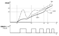
- FIG. 7 is a time chart showing motor rotation speed (hereinafter referred to as Nm) and changes in VSP1, VSP2, and VSP.
- Nm motor rotation speed
- VSP1 suddenly rises and the difference between Nm and the average rotational speed of the left and right driven wheels changes abruptly.
- the vibration suppression control torque calculation unit 603 calculates the first vibration suppression control torque associated with the change in the difference, the vibration suppression control torque may fluctuate and may cause a shock. Therefore, in the first embodiment, the vibration suppression control is performed using VSP2 estimated based on Nm having a high resolution even in the extremely low vehicle speed range.
- FIG. 5 is a flowchart illustrating a control process in the vehicle body speed selection unit according to the first embodiment.
- step S1 it is determined whether Nm is less than a predetermined rotational speed A1 (hereinafter also referred to as A1). If it is less than A1, the process proceeds to step S2 to select VSP2, and if it is greater than A1, the process proceeds to step S3. move on.
- the predetermined rotational speed A1 is a predetermined speed at which the wheel speed sensor 10 can determine the speed.
- step S3 it is determined whether or not Nm is equal to or higher than a predetermined rotational speed A2 (hereinafter also referred to as A2). If it is equal to or higher than A2, the process proceeds to step S4 and VSP1 is selected.
- the predetermined rotation speed A2 is a value larger than A1, and is a predetermined speed at which control hunting can be avoided. As a result, hysteresis can be given to switching between VSP1 and VSP2, and stable damping performance is ensured by suppressing control hunting.
- step S5 when switching VSP, switching control for smoothly switching is executed. Details of the switching control will be described below.
- FIG. 6 is a control block diagram illustrating the switching control process of the first embodiment.
- the previous value is represented by (1 / Z).
- the VSP switching unit 700 outputs the switched VSP according to the value of the switching flag Fmm.
- the first difference calculation unit 702a is the difference between the VSP after switching and the previous value of the VSP currently output in the previous value output unit 708 (hereinafter referred to as the previous VSP). One difference is calculated.
- the limiting unit 702b if the first difference does not exceed the preset maximum and minimum limit values, the first difference is output as it is, and if it exceeds the limit value, the limit value is output. Is output. Thereby, when switching the estimated vehicle body speed, a transition speed (allowable change amount per unit time at the time of transition) when the vehicle body speed is shifted from one vehicle body speed is set.
- the second difference calculation unit 703a calculates a second difference that is a difference between the switched VSP and the previous value of the switched VSP.
- the compensation determination unit 703b outputs the second difference when Fch is ON, and outputs 0 when Fch is OFF.
- the adding unit 703C outputs a third difference obtained by adding the value output from the transition speed determining unit 702 and the second difference.
- the transition VSP calculation unit 706 the previous value of VSP is added to the third difference. As a result, even during the transition accompanying the switching of the VSP, the transitioning VSP can be output at the managed transition speed while compensating for the change due to the VSP after the switching.
- the final output determining unit 707 outputs either the post-switching VSP or the in-transition VSP based on the determination result of the in-transition processing determination unit 705.
- FIG. 7 is a time chart when the electric vehicle according to the first embodiment starts. Initially, the vehicle is stopped and VSP2 is selected. When the driver depresses the accelerator pedal at the time t1 to start, Nm changes abruptly including the twist. At this time, VSP2 changes gently by the low-pass filter. At this point, VSP1 is outputting an appropriate 0. At time t2, the wheel speed sensor 10 reaches a vehicle speed at which a pulse signal can be detected, but Nm is still less than A2, so VSP2 becomes VSP. When Nm reaches A2 at time t3 and the switching flag Fmm is switched from F21 to F12, the transition processing flag Ftra changes from 0 to 1.
- VSP As the VSP, a value gradually asymptotically output from VSP2 to VSP1 is output.
- VSP and VSP1 match at time t4, the migration processing flag Ftra changes from 1 to 0, and VSP1 is output as VSP. This completes the switching.
- vibration control performance is achieved by approaching VSP1 after switching while considering the change in VSP1 after switching. It is possible to realize switching without causing the driver to feel uncomfortable while securing the vehicle.
- Example 1 has the following operational effects.
- a control device for an electric vehicle that drives wheels by the electric motor 1, and a vibration suppression control torque calculated by a first estimation unit 6021 (first calculation method) based on a signal from the wheel speed sensor 10;
- the vehicle body speed selection unit 6023 and the first control unit that selectively output the vibration suppression control torque calculated by the second estimation unit 6022 (second calculation method) based on signals other than the signal of the wheel speed sensor 10.
- a vibration control torque calculation unit 603 (a vibration suppression control torque calculation unit) and a drive torque command value calculation unit 606 (which calculates a motor torque command for driving the electric motor 1 based on the requested drive torque and the vibration suppression control torque) Motor torque command calculation unit).
- the first estimation unit 6021 calculates VSP1, which is an estimated value of the vehicle body speed, based on the signal from the wheel speed sensor 10. Therefore, it is possible to suppress vibration caused by the twist between the electric motor 1 and the wheels.
- the second estimation unit 6022 calculates VSP2, which is an estimated value of the vehicle body speed, based on the motor rotation speed Nm of the electric motor 1. That is, the resolver 8 that is essential in the electric vehicle has high resolution, and can detect the rotational speed information with high accuracy even when starting.
- the vehicle body speed selection unit 6023 selects VSP2 when the motor rotation speed Nm of the electric motor 1 is less than A1 (first threshold). Therefore, VSP2 can be estimated by the resolver 8 even in a region that may not be detected by the wheel speed sensor 10.
- the vehicle speed selection unit 6023 selects VSP1 when the motor rotation speed Nm of the electric motor is equal to or higher than A2 (second threshold) larger than A1 when VSP2 is selected.
- the signal of the wheel speed sensor 10 can be used in a state that can be estimated by the wheel speed sensor 10 while avoiding control hunting associated with switching between VSP1 and VSP2.
- the signal of the wheel speed sensor 10 is based on the rotational speed on the driven wheel side. Therefore, an appropriate vibration suppression control torque can be calculated for torsional vibration regardless of the road surface ⁇ , and the effect of suppressing torsional vibration can be improved.
- the second estimation unit 6022 (first) based on the vibration control torque calculated by the first estimation unit 6021 (first calculation method) based on the signal of the wheel speed sensor 10 and other signals excluding the signal of the wheel speed sensor 10
- Vehicle speed selection unit 6023 and first vibration suppression control torque calculation unit 603 (vibration control torque calculation unit) that selectively output the vibration suppression control torque calculated by the calculation method 2)
- a drive torque command value calculation unit 606 (motor torque command calculation unit) that calculates a motor torque command for driving the electric motor 1 based on the requested drive torque and vibration suppression control torque. Therefore, the shock at the time of starting from a stop can be suppressed.
- the first estimation unit 6021 calculates VSP1 that is an estimated value of the vehicle body speed based on the signal from the wheel speed sensor 10, and the second estimation unit 6022 Calculates VSP2, which is an estimated value of the vehicle body speed, based on the motor rotation speed Nm of the electric motor 1. Therefore, by using the motor rotation speed Nm, it is possible to suppress a shock at the time of starting from a stop and to suppress vibration caused by torsion between the electric motor 1 and the wheels.
- the vehicle body speed selection unit 6023 selects VSP2 when the motor rotation speed Nm of the electric motor 1 is less than A1 (first threshold).
- VSP2 can be estimated by the resolver 8 even in a region that may not be detected by the wheel speed sensor 10.
- the vehicle speed selection unit 6023 selects VSP1 when the motor rotation speed Nm of the electric motor is equal to or higher than A2 (second threshold) larger than A1 when VSP2 is selected. Therefore, the signal of the wheel speed sensor 10 can be used in a state that can be estimated by the wheel speed sensor 10 while avoiding control hunting associated with switching between VSP1 and VSP2.
- a method for controlling an electric vehicle in which wheels are driven by the electric motor 1 The wheel speed sensor 10 for detecting the wheel speed signal, the vibration suppression control torque calculated by the first estimation unit 6021 (first calculation method) based on the signal of the wheel speed sensor 10, and the signal of the wheel speed sensor 10
- a vibration suppression control torque calculation step for selectively outputting the vibration suppression control torque calculated by the second estimation unit 6022 (second calculation method) based on the other signals except;
- a motor torque command calculation step for calculating a motor torque command for driving the electric motor 1 based on the requested drive torque and vibration suppression control torque. Therefore, the shock at the time of starting from a stop can be suppressed.
- the first estimation unit 6021 calculates VSP1, which is an estimated value of the vehicle body speed, based on the signal from the wheel speed sensor 10, and the second estimation unit 6022 estimates the vehicle body speed based on the motor rotation speed Nm of the electric motor 1.
- VSP2 is calculated. Therefore, by using the motor rotation speed Nm, it is possible to suppress a shock at the time of starting from a stop and to suppress vibration caused by torsion between the electric motor 1 and the wheels.
- the vibration suppression control torque calculation step selects VSP2 when the motor rotation speed Nm of the electric motor 1 is less than A1 (first threshold value).
- VSP2 can be estimated by the resolver 8 even in a region that may not be detected by the wheel speed sensor 10.
- VSP1 is selected when the motor rotation speed Nm of the electric motor is equal to or higher than A2 (second threshold value) greater than A1. Therefore, the signal of the wheel speed sensor 10 can be used in a state that can be estimated by the wheel speed sensor 10 while avoiding control hunting associated with switching between VSP1 and VSP2.
- Example 2 Next, Example 2 will be described. Since the basic configuration is the same as that of the first embodiment, different points will be described.
- the vehicle body speed selection unit 6023 switches the estimated vehicle body speed based on the motor rotation speed Nm.
- the estimated vehicle body speed is switched based on the driving wheel speed VF which is an average value of signals detected by the front left wheel speed sensor 10FL and the front right wheel speed sensor 10FR which are driving wheels. is there.
- FIG. 8 is a flowchart illustrating a control process in the vehicle body speed selection unit according to the second embodiment. Steps S11 to S15 are substantially the same as steps S1 to S5 shown in FIG. 5 of the first embodiment. In steps S11 and S13, VF is used instead of Nm in steps S1 and S3 of FIG. Different. Thereby, there exists an effect similar to Example 1.
- FIG. 1 the vehicle body speed selection unit 6023 switches the estimated vehicle body speed based on the motor rotation speed Nm.
- the driving wheel speed VF which is an average value of signals detected by the front left
- the signal of the wheel speed sensor is based on the rotational speed on the drive wheel side. Therefore, the shock at the time of starting from a stop can be suppressed.
- the vehicle body speed selection unit 6023 selects VSP2 when the signal VF of the wheel speed sensor 10 on the drive wheel side is less than A1 (third threshold value). Therefore, VSP2 can be estimated by the resolver 8 even in a region that may not be detected by the wheel speed sensor 10.
- the vehicle speed selection unit 6023 selects VSP1 when VSP2 is selected and VF is greater than or equal to A2 (second threshold) greater than A1. Therefore, the signal of the wheel speed sensor 10 can be used in a state that can be estimated by the wheel speed sensor 10 while avoiding control hunting associated with switching between VSP1 and VSP2.
- FIG. 9 is a control block diagram of the vehicle controller 6 according to the third embodiment.
- the first embodiment only the first vibration suppression control torque calculation unit 603 is provided.
- a second damping control torque calculating unit 603 is provided, and either one of the first damping control torque and the second damping control torque is provided.
- a selection unit 605 for selecting is provided.
- the vehicle body speed estimation unit 602 includes a first estimation unit 6021, a second estimation unit 6022, and a vehicle body speed selection unit 6023.
- the vehicle body speed estimation unit 602 includes only a vehicle body speed estimation unit corresponding to the first estimation unit 6021 of the first embodiment, and includes a second estimation unit 6022 and a vehicle body speed selection unit 6023. Absent.
- the first damping control torque calculation unit 603 corresponds to the first calculation method described in the claims, and the second damping control torque calculation unit 604 corresponds to the second calculation method described in the claims. To do.
- the second vibration suppression control torque calculator 604 calculates the second vibration suppression control torque based on the motor rotation speed.
- Multiplier 604a multiplies the motor rotation speed by -1 to invert the sign.
- the high-pass filter 604b decreases the vibration component having a predetermined frequency or less from the output of the multiplier 604a.
- the cut-off frequency of the high-pass filter 604b is a frequency corresponding to the vehicle speed (for example, about 1 Hz) in consideration of the inertia of the vehicle.
- the high-pass filter type vibration suppression control torque calculator 604c calculates a second vibration suppression control torque based on the vibration component that has passed through the high-pass filter 604b.
- the gain multiplication unit 604c-1 outputs a value obtained by multiplying the vibration component that has passed through the high-pass filter 604b by a predetermined control gain K as the second vibration suppression control torque.
- the limiter processing unit 604c-2 limits the upper and lower limit values of the second vibration suppression control torque within a certain range.
- the selection unit 605 selects one of the first vibration suppression control torque calculated by the first vibration suppression control torque calculation unit 603 and the second vibration suppression control torque calculated by the second vibration suppression control torque calculation unit 604. And output as vibration suppression control torque.
- the selection unit 605 selects one of the first vibration suppression control torque and the second vibration suppression control torque according to the motor rotation speed.
- the selection unit 605 aims to simplify the control, and always selects the first vibration suppression control torque when the vehicle is started.
- the drive torque command value calculation unit 606 calculates the drive torque command value by adding the driver request drive torque calculated by the driver request drive torque calculation unit 601 and the vibration suppression control torque output from the selection unit 605. To do.
- FIG. 10 is a flowchart illustrating a control process in the selection unit according to the third embodiment.
- step S21 it is determined whether or not the motor rotation speed Nm is less than a predetermined rotation speed A1, and if it is less than A1, the process proceeds to step S22 to select the second vibration suppression control torque, and if it is greater than A1, the process proceeds to step S23. .
- step S23 it is determined whether or not the motor rotation speed Nm is equal to or higher than the predetermined rotation speed A2. If the motor rotation speed Nm is equal to or higher than A2, the process proceeds to step S24 to select the first vibration suppression control torque.
- the predetermined rotational speed A2 is a predetermined speed at which control hunting can be avoided. Thereby, hysteresis can be given to switching between the first vibration suppression control torque and the second vibration suppression control torque, and stable vibration suppression performance is ensured by suppressing control hunting.
- step S25 when switching the vibration suppression control torque, the switching control for smoothly switching is executed. Details of the switching control will be described below.
- FIG. 11 is a control block diagram illustrating the switching control process of the third embodiment.
- the previous value is represented by (1 / Z).
- the torque switching unit 700 outputs a post-switching vibration damping control torque corresponding to the value of the switching flag Fmm.
- the second vibration suppression control torque is the post-switching vibration suppression control torque
- the transition speed determination unit 702 in the first difference calculation unit 702a, the post-switching vibration suppression control torque and the previous value of the vibration suppression control torque currently output in the previous value output unit 708 (hereinafter referred to as the previous vibration suppression control torque).
- the limiting unit 702b if the first difference does not exceed the preset maximum and minimum limit values, the first difference is output as it is, and if it exceeds the limit value, the limit value is output. Is output. Thereby, when switching the vibration suppression control torque, the transition speed (allowable change amount per unit time at the time of transition) when shifting from one vibration suppression control torque to the other vibration suppression control torque is set.
- the second difference calculation unit 703a calculates a second difference that is a difference between the post-switching vibration suppression control torque and the post-switching vibration suppression control torque previous value.
- the compensation determination unit 703b outputs the second difference when Fch is ON, and outputs 0 when Fch is OFF.
- the adding unit 703C outputs a third difference obtained by adding the value output from the transition speed determining unit 702 and the second difference.
- the transitional vibration suppression control torque calculation unit 706 adds the previous value of the vibration suppression control torque to the third difference. Thus, even during the transition due to switching of the vibration suppression control torque, it is possible to output the vibration suppression control torque during the transition at the managed transition speed while compensating for the change caused by the post-switching vibration suppression control torque.
- the final output determination unit 707 outputs one of the post-switching vibration suppression control torque and the in-transition vibration suppression control torque based on the determination result of the transition processing determination unit 705.
- FIG. 12 is a time chart illustrating the switching control process of the third embodiment.
- the vehicle is traveling in the R range, and the second vibration suppression control torque is selected.
- the transition processing flag Ftra is changed from 0 to 1.
- the vibration suppression control torque a value gradually asymptotically output from the second vibration suppression control torque to the first vibration suppression control torque is output.
- the transition processing flag Ftra changes from 1 to 0, and the first vibration suppression control torque is output as the vibration suppression control torque. This completes the switching.
- the vibration suppression control torque when the vibration suppression control torque is switched, even if there is a difference between the first vibration suppression control torque and the second vibration suppression control torque, the switching is performed in consideration of the change in the vibration suppression control torque after the switching. Asymptotically approaching the later vibration suppression control torque, it is possible to realize switching without causing the driver to feel uncomfortable while ensuring the vibration suppression performance.
- FIG. 13 is a control block diagram of the vehicle controller 6 of the fourth embodiment.
- the second estimation unit 6022 outputs a value obtained by passing a low-pass filter for the motor rotation speed Nm.
- the fourth embodiment is different in that a longitudinal acceleration sensor 6020 for detecting the longitudinal acceleration of the electric vehicle is provided instead of the motor rotation speed Nm.
- the second estimation unit 6022a integrates the detected longitudinal acceleration signal (hereinafter also referred to as Gx) (corresponding to 1 / s in FIG. 13) to calculate VSP2.
- Gx detected longitudinal acceleration signal
- Second estimation unit 6022 calculates an estimated value VSP2 of the vehicle body speed based on a signal from longitudinal acceleration sensor 6020 of the vehicle. Therefore, since the vehicle body speed is estimated based on the sensor value with an early phase, it is possible to execute the vibration suppression control at the time of starting with high accuracy.
- FIG. 14 is a control block diagram of the vehicle controller 6 of the fifth embodiment.
- the second estimation unit 6022 outputs a value obtained by passing a low-pass filter for the motor rotation speed Nm.
- the fifth embodiment is different in that VSP2 is calculated using a vehicle acceleration model based on the driver required driving torque instead of the motor rotation speed Nm.
- the second estimation unit 6022b converts the driver request drive torque into the vehicle longitudinal force Fd, and calculates VSP2 from the equation of motion based on Fd. If the weight of the electric vehicle is W, the acceleration generated by the electric vehicle is Fd / W.
- VSP2 is calculated. As a result, even when starting from a stop where the resolution of the wheel speed sensor 10 is difficult to obtain, the VSP2 can be detected with high accuracy based on the driver-requested driving torque, and the same effects as those of the first embodiment can be obtained.
- the second estimating unit 6022 calculates the estimated value VSP2 of the vehicle body speed based on the vehicle acceleration model estimated by the equation of motion. Accordingly, the vehicle body speed can be estimated from the driver demanded drive torque with a fast phase, and the vibration suppression control at the time of start can be executed with high accuracy.
- the concrete structure of this invention is not limited to the structure shown in the Example, and is the range which does not deviate from the summary of invention. Any design changes are included in the present invention.
- any combination or omission of each constituent element described in the claims and the specification is possible within a range where at least a part of the above-described problems can be solved or a range where at least a part of the effect is achieved.
- the electric vehicle has been described as an example, but the present invention can be applied to a hybrid vehicle including both an engine and an electric motor.
- the first vibration damping control torque is calculated, the calculation is performed based on the rotational speed on the driven wheel side, but may be performed based on the rotational speed on the drive wheel side.
Landscapes
- Engineering & Computer Science (AREA)
- Transportation (AREA)
- Mechanical Engineering (AREA)
- Automation & Control Theory (AREA)
- Power Engineering (AREA)
- Chemical & Material Sciences (AREA)
- Combustion & Propulsion (AREA)
- Human Computer Interaction (AREA)
- Electric Propulsion And Braking For Vehicles (AREA)
Abstract
本発明の目的は、停車から発進するときにショックを抑制可能な電動車両の制御装置を提供すること。 本発明の一実施形態では、車輪速センサの信号に基づく第1の演算方式により演算された第1制振制御トルクと、車輪速センサの信号以外の信号に基づく第2の演算方式により演算された第2制振制御トルクとが、選択的に出力される。
Description
本発明は、電動車両の制御装置、制御システム及び制御方法に関する。
従来の電動車両の制御装置では、モータ回転速度と左右駆動輪の平均回転速度との差分をトルク伝達系のねじり振動の振動成分として抽出し、この振動成分を打ち消すための制振制御トルクを演算し、運転者要求駆動トルクを補正している。上記説明の技術に関する一例は、特許文献1に記載されている。
しかしながら、一般的に、低車速域での車輪速センサの信号の分解能が低いため、分解能が高いモータ回転速度と分解能が低い左右駆動輪の平均回転速度との差分のみを用いると、停車から発進する際にモータ回転速度信号との差分が急変する場合がある。この差分の急変に伴い、大きな制振制御トルクが演算されることで、ショックが発生するおそれがあった。
本発明の目的は、停車から発進するときにショックを抑制可能な電動車両の制御装置を提供することにある。
本発明の目的は、停車から発進するときにショックを抑制可能な電動車両の制御装置を提供することにある。
本発明の一実施形態では、車輪速センサの信号に基づく第1の演算方式により演算された第1制振制御トルクと、車輪速センサの信号以外の信号に基づく第2の演算方式により演算された第2制振制御トルクとが、選択的に出力される。
よって、停車から発進する際のショックを抑制できる。
〔実施例1〕
図1は実施例1の電動車両のシステム図である。実施例1の電動車両は、前輪FL,FRが電動モータ1により駆動される前輪駆動車(二輪駆動車)である。電動モータ1には減速機構2を介してディファレンシャルギア3が接続されている。ディファレンシャルギア3にはドライブシャフト4が接続されている。ドライブシャフト4には前輪FL,FRが接続されている。電動モータ1は、インバータ5を介して図外の高電圧バッテリから電力が供給される。インバータ5の駆動は、車両コントローラ6により制御される。
図1は実施例1の電動車両のシステム図である。実施例1の電動車両は、前輪FL,FRが電動モータ1により駆動される前輪駆動車(二輪駆動車)である。電動モータ1には減速機構2を介してディファレンシャルギア3が接続されている。ディファレンシャルギア3にはドライブシャフト4が接続されている。ドライブシャフト4には前輪FL,FRが接続されている。電動モータ1は、インバータ5を介して図外の高電圧バッテリから電力が供給される。インバータ5の駆動は、車両コントローラ6により制御される。
電動車両は、車両の走行モードを表すレンジ位置信号を出力するシフトレバー12と、アクセル開度信号を出力するアクセル開度センサ7と、電動モータ1の回転方向を含むモータ回転速度信号を出力するレゾルバ8と、を有する。車両コントローラ6は、シフトレバー12からのレンジ位置信号と、アクセル開度センサ7からのアクセル開度信号とを受信する第1の受信部を有する。また、車両コントローラ6は、レゾルバ8からのモータ回転速度信号を、インバータ5を介して受信する第2の受信部を有する。シフトレバー12は、運転者により操作され、車両停車時はパーキングレンジ(以下、Pレンジ)、非動力伝達時はニュートラルレンジ(以下、Nレンジ)、前進時はドライブレンジ(以下、Dレンジ)、後退時はリバースレンジ(以下、Rレンジ)のレンジ位置信号を出力する。
インバータ5は、ブレーキコントローラ9を介して後輪RL,RRの車輪速度(左従動輪速度,右従動輪速度)を受信する。ブレーキコントローラ9は、各輪に設けられた車輪速センサ10FL,10FR,10RL,10RR(以下、単に10とも記載する。)と接続され、各輪の回転速度信号を受信する。車輪速センサ10は、電磁バルスの周期から車輪速を検出する。ブレーキコントローラ9は、運転者のブレーキ操作量に基づき、各輪のブレーキユニットに供給するブレーキ液を調整し、各輪の制動トルクを制御する。インバータ5、車両コントローラ6およびブレーキコントローラ9の情報通信は、CAN通信線(通信装置)11を介して行われる。車両コントローラ6は、アクセル開度等に基づいて電動モータ1の駆動トルク指令値を演算し、駆動トルク指令値に応じてインバータ5を駆動する。
図2は、実施例1の車両コントローラ6の制御ブロック図である。
運転者要求駆動トルク演算部601は、アクセル開度に基づき運転者要求駆動トルクを演算する。運転者要求駆動トルクは、アクセル開度が高いほど大きな値とする。
車体速度推定部602は、後左車輪速センサ10RLおよび後右車輪速センサ10RRにより検出された左右従動輪速度から車体速度を推定する第1推定部6021(以下、従動輪車輪速度から推定された車体速度をVSP1とも記載する。)と、レゾルバ8により検出されたモータ回転速度から車体速度を推定する第2推定部6022(以下、モータ回転速度から推定された車体速度をVSP2とも記載する。)と、第1推定部6021と第2推定部6022とのうち、一方の車体速度を選択して出力する車体速度選択部6023(以下、車体速度選択部6023において選択された推定車体速度をVSPとも記載する。)と、を有する。
第1推定部6021は、加算部602aと、除算部602bとを有する。加算部602aは、左右従動輪速度を加算する。除算部602bは、加算部602aの出力を2で除した値、すなわち、左右従動輪速度の平均値をVSP1として出力する。
第2推定部6022は、ローパスフィルタであり、モータ回転速度のうち、車両のイナーシャを考慮した周波数帯を抽出した値をVSP2として出力する。
運転者要求駆動トルク演算部601は、アクセル開度に基づき運転者要求駆動トルクを演算する。運転者要求駆動トルクは、アクセル開度が高いほど大きな値とする。
車体速度推定部602は、後左車輪速センサ10RLおよび後右車輪速センサ10RRにより検出された左右従動輪速度から車体速度を推定する第1推定部6021(以下、従動輪車輪速度から推定された車体速度をVSP1とも記載する。)と、レゾルバ8により検出されたモータ回転速度から車体速度を推定する第2推定部6022(以下、モータ回転速度から推定された車体速度をVSP2とも記載する。)と、第1推定部6021と第2推定部6022とのうち、一方の車体速度を選択して出力する車体速度選択部6023(以下、車体速度選択部6023において選択された推定車体速度をVSPとも記載する。)と、を有する。
第1推定部6021は、加算部602aと、除算部602bとを有する。加算部602aは、左右従動輪速度を加算する。除算部602bは、加算部602aの出力を2で除した値、すなわち、左右従動輪速度の平均値をVSP1として出力する。
第2推定部6022は、ローパスフィルタであり、モータ回転速度のうち、車両のイナーシャを考慮した周波数帯を抽出した値をVSP2として出力する。
第1制振制御トルク演算部603は、車体速度推定部602により推定されたVSPとレゾルバ8により検出されたモータ回転速度とに基づいて第1制振制御トルクを演算する。乗算部603aは、VSPに総減速比(減速機構2の減速比×ディファレンシャルギア3の減速比)を乗じる。減算部603bは、乗算部603aの出力からモータ回転速度を減じてモータ回転速度に含まれる振動成分を抽出する。ハイパスフィルタ603cは、減算部603bの出力から定常偏差(タイヤ動半径の計算と実際のずれによる偏差)成分を低減させる。ハイパスフィルタ603cのカットオフ周波数は、車輪スリップを検出可能な値(例えば、1Hz未満)とする。ゲイン乗算部603dは、ハイパスフィルタ603cを通過した振動成分に所定の制御ゲインKを乗じた値を第1制振制御トルクとして出力する。リミッタ処理部603eは、第1制振制御トルクの上下限値を一定範囲内に制限する。
[ねじり振動の抑制効果の向上]
電動車両において、急加速時にモータトルクをステップ的に立ち上げると、ドライブシャフトのねじれと解放が繰り返されることに起因してトルク伝達系にねじり振動が生じる。電動モータはエンジンに対してトルク応答性が高いため、ねじり振動がマウントを介して車体に伝達されると、特に車体の共振周波数と重なったとき、乗り心地の低下や振動・騒音レベルの増大を招く。そこで、従来の電動車両では、モータ回転速度と左右駆動輪の平均回転速度(駆動輪速度)との差分をねじり振動の振動成分として抽出し、この振動成分を打ち消すための制振制御トルクを演算して運転者要求駆動トルクを補正している。
しかしながら、モータ回転速度と駆動輪速度との差分から制振制御トルクを求める場合、特に低μ路走行中のねじり振動に対して適切な制振制御トルクを演算できず、十分な振動抑制効果が得られない。以下にその理由を説明する。
電動車両において、急加速時にモータトルクをステップ的に立ち上げると、ドライブシャフトのねじれと解放が繰り返されることに起因してトルク伝達系にねじり振動が生じる。電動モータはエンジンに対してトルク応答性が高いため、ねじり振動がマウントを介して車体に伝達されると、特に車体の共振周波数と重なったとき、乗り心地の低下や振動・騒音レベルの増大を招く。そこで、従来の電動車両では、モータ回転速度と左右駆動輪の平均回転速度(駆動輪速度)との差分をねじり振動の振動成分として抽出し、この振動成分を打ち消すための制振制御トルクを演算して運転者要求駆動トルクを補正している。
しかしながら、モータ回転速度と駆動輪速度との差分から制振制御トルクを求める場合、特に低μ路走行中のねじり振動に対して適切な制振制御トルクを演算できず、十分な振動抑制効果が得られない。以下にその理由を説明する。
一般的に、各輪の回転速度は車輪速センサにより検出されてブレーキコントローラへ入力されるため、電動モータを制御するコントローラは、CAN通信線を介してブレーキコントローラから駆動輪速度信号を取得することになる。よって、実際の駆動輪速度(センサ検出値)に対してコントローラが取得する駆動輪速度には通信遅れが生じる。一方、モータ回転速度はレゾルバから直接コントローラへ入力されるため、通信遅れは生じない。ここで、低μ路で車輪のスリップが生じると、タイヤの見かけの慣性から車両質量が切り離されるため、見かけのタイヤ慣性が小さくなる。そのため、低μ路におけるねじり振動の周波数(10~20Hz程度)は、高μ路におけるねじり振動の周波数(5~9Hz程度)よりも高い。このため、低μ路走行中に制振制動トルクを演算する際、モータ回転速度の振動と駆動輪速度の振動との位相ズレが生じ、不適切(位相のズレた)な制振制動トルクが演算される。
なお、上記の通信遅れによる影響を回避する方法としては、CAN通信線を介さずに車輪速センサから直接駆動輪速度を入力する方法、モータ回転速度からハイパスフィルタを用いて制振制御トルクを演算する方法が知られている。しかしながら、前者にあっては、回路の追加等、コストアップが問題となる。また、後者にあっては、駆動輪のスリップによりスリップ初期に位相のズレた制振制御トルクが演算されることで、スリップ制御性能の低下を招く。図3は、ハイパスフィルタを用いて制振制御トルクを演算した場合の車輪速度、駆動トルクおよび振動検出値のタイムチャートである。ハイパスフィルタを用いた方法では、駆動輪のスリップ(=モータ速度の上昇)と急加速を判別できないため、スリップ初期において駆動輪のスリップに対し位相のズレた制振制御トルクが演算される。よって、モータ回転速度及び駆動輪速度が安定せず、スリップ制御性能が低下している。
これに対し、実施例1では、第1制振制御トルク演算部603において、モータ回転速度と左右従動輪速度から推定した車体速度との差分に基づいて第1制振制御トルクを演算している。車体速度は車輪のスリップ状態にかかわらず振動しないため、モータ回転速度との位相ズレは生じない。また、モータ回転速度から車体速度を減じることで加速成分と駆動輪のスリップとを区別できる。よって、車輪のスリップ状態にかかわらずねじり振動に対して適切な第1制振制御トルクを演算でき、ねじり振動の抑制効果を向上できる。図4は、実施例1の従動輪速方式で制振制御トルクを求めた場合のねじり振動抑制作用を示すタイムチャートである。実施例1では、駆動輪のスリップに対して位相ズレなく振動を検出できるため、モータ回転速度及び駆動輪速度が安定しており、スリップ制御を阻害することがなく、スリップの収束性能に優れている。さらに、通信遅れの影響を受けないため、ブレーキコントローラ9からCAN通信線11を介して左右従動輪速度を取り込む従前のシステムに適用できる。よって、車輪速センサ10から直接従動輪速度を入力する回路等の追加が不要であるため、システムの複雑化およびコストアップを抑制できる。
ここで、VSP1とVSP2のいずれか一方を選択する理由について説明する。上述したように、車輪速センサ10が出力する信号は、パルス信号である。図7はモータ回転速度(以下、Nmと記載する。)と、VSP1とVSP2とVSPの変化を表すタイムチャートである。図7の細い実線で示すように、停車状態からの発進時では、パルスが複数生じる距離分タイヤが転がり、そのパルスの時間間隔から速度を算出するため、速度を確定するときには既に実速度が生じている。そのため、VSP1は突然立ち上がり、Nmと左右従動輪の平均回転速度との差分が急激に変化する。そうすると、第1制振制御トルク演算部603では、この差分の変化に伴う第1制振制御トルクを演算するため、制振制御トルクが変動し、ショックを招くおそれがあった。そこで、実施例1では、極低車速域でも分解能が高いNmに基づいて推定されたVSP2を用いて制振制御を行うこととした。
図5は実施例1の車体速度選択部における制御処理を表すフローチャートである。
ステップS1では、Nmが所定回転速度A1(以下、A1とも記載する。)未満か否かを判断し、A1未満のときはステップS2に進んでVSP2を選択し、A1以上のときはステップS3に進む。ここで、所定回転速度A1は、車輪速センサ10が速度を確定できる所定速度である。
ステップS1では、Nmが所定回転速度A1(以下、A1とも記載する。)未満か否かを判断し、A1未満のときはステップS2に進んでVSP2を選択し、A1以上のときはステップS3に進む。ここで、所定回転速度A1は、車輪速センサ10が速度を確定できる所定速度である。
ステップS3では、Nmが所定回転速度A2(以下、A2とも記載する。)以上か否かを判断し、A2以上のときはステップS4に進んでVSP1を選択し、A2未満の場合はステップS1に戻る。ここで、所定回転速度A2は、A1よりも大きな値であり、制御ハンチングを回避可能な所定速度である。これにより、VSP1とVSP2との切り替えにヒステリシスを持たせることができ、制御ハンチングを抑制することで安定した制振性能を確保する。
ステップS5では、VSPを切り替える際に、スムーズに切り替える切り替え制御を実行する。以下、切り替え制御の詳細について説明する。
ステップS5では、VSPを切り替える際に、スムーズに切り替える切り替え制御を実行する。以下、切り替え制御の詳細について説明する。
(切り替え制御処理について) 図6は実施例1の切り替え制御処理を表す制御ブロック図である。図中、(1/Z)で表されるのは、前回値である。切り替えフラグFmmは、VSP1からVSP2への切り替えが起こったときはFmm=F12を出力し、VSP2からVSP2への切り替えが起こった時はFmm=F21を出力する。
VSP切り替え部700では、切り替えフラグFmmの値に応じた切り替え後VSPを出力する。言い換えると、Fmm=F12のときはVSP2が切り替え後VSPであり、Fmm=F21のときはVSP1が切り替え後VSPである。
VSP切り替え部700では、切り替えフラグFmmの値に応じた切り替え後VSPを出力する。言い換えると、Fmm=F12のときはVSP2が切り替え後VSPであり、Fmm=F21のときはVSP1が切り替え後VSPである。
移行処理開始判断部701では、判断部701aにおいて切り替えフラグFmmの値が前回値と不一致か否かを判断し、不一致のとき(F12→F21への切り替え、もしくはF21→F12への切り替え)が起こったときはFch=ONを出力し、それ以外の場合はFch=OFFを出力する。
移行速度決定部702では、第1差分演算部702aにおいて、切り替え後VSPと前回値出力部708において現在出力されているVSPの前回値(以下、前回VSPと記載する。)との差分である第1差分を演算する。次に、制限部702bでは、第1差分が予め設定された変化量の最大及び最小の制限値を超えていない場合は、第1差分をそのまま出力し、制限値を超えている場合は制限値を出力する。これにより、推定された車体速度を切り替える際に、一方の車体速度から他方の車体速度へ移行する際の移行速度(移行時の単位時間当たりにおける許容変化量)を設定する。
移行速度決定部702では、第1差分演算部702aにおいて、切り替え後VSPと前回値出力部708において現在出力されているVSPの前回値(以下、前回VSPと記載する。)との差分である第1差分を演算する。次に、制限部702bでは、第1差分が予め設定された変化量の最大及び最小の制限値を超えていない場合は、第1差分をそのまま出力し、制限値を超えている場合は制限値を出力する。これにより、推定された車体速度を切り替える際に、一方の車体速度から他方の車体速度へ移行する際の移行速度(移行時の単位時間当たりにおける許容変化量)を設定する。
移行中制振性能補償部703では、第2差分演算部703aにおいて、切り替え後VSPと切り替え後VSP前回値との差分である第2差分を演算する。次に、補償判断部703bにおいて、FchがONのときは第2差分を出力し、FchがOFFのときは0を出力する。そして、加算部703Cにおいて、移行速度決定部702から出力された値と、第2差分とを加算した第3差分を出力する。これにより、完全に切り替え後VSPに切り替えられる前であっても、切り替え後VSPの変化分を補償し、制振性能を確保する。
移行処理終了判断部704では、第1差分と制限後の第1差分(制限値もしくは第1差分のいずれか)とが一致するか否かを判断し、一致するときは第1差分が制限値よりも小さため、VSPが切り替え後VSPに追いついたと判断してFend=ONを出力し、一致していないときは制限されている状態であり、まだVSPが切り替え後VSPに追いついていないと判断してFend=OFFを出力する。
移行処理中判断部705では、第1判断部705aにおいて、FchがOFFのときは移行処理中フラグFtra=1を出力し、FchがONのときは後述する第2判断部705bの判断結果を出力する。第2判断部705bでは、FendがONのときは0を出力し、FendがOFFのときは第1判断部705aから出力された値の前回値を出力する。言い換えると、VSPの切り替え要求が出力されたときは、一旦Ftra=1を出力し、その後、切り替え要求が終了すると、第2判断部705bの判断結果に切り替える。このとき、FendがOFFの間は第2判断部705bの判断結果が1であるから、第1判断部705aからは継続的にFtra=1が出力される。その後、第2判断部705bの判断結果が0となると、第1判断部705aにも0が出力されるため、第1判断部705aからFtr=0が出力される。
移行中VSP演算部706では、第3差分にVSP前回値を加算する。これにより、VSPの切り替えに伴う移行中であっても、切り替え後VSPによる変化分を補償しつつ、管理された移行速度によって移行中VSPを出力できる。
最終出力判断部707では、移行処理中判断部705の判断結果に基づいて、切り替え後VSPと移行中VSPとのうち、いずれかを出力する。
最終出力判断部707では、移行処理中判断部705の判断結果に基づいて、切り替え後VSPと移行中VSPとのうち、いずれかを出力する。
図7は実施例1の電動車両が発進するときのタイムチャートである。最初は車両停止中であって、VSP2が選択された状態である。
時刻t1において、運転者がアクセルペダルを踏みこんで発進すると、Nmは捩れ分も含めて急激に変化する。このとき、VSP2はローパスフィルタによって緩やかに変化する。尚、この時点では、VSP1は適正な0を出力している。
時刻t2において、車輪速センサ10がパルス信号を検出可能な車速に到達するものの、まだNmがA2未満であるためVSP2がVSPとなる。
時刻t3において、NmがA2に到達し、切り替えフラグFmmがF21からF12に切り替わると、移行処理中フラグFtraが0から1に変化する。そして、VSPは、VSP2からVSP1へと徐々に漸近した値が出力される。
時刻t4において、VSPとVSP1とが一致すると、移行処理中フラグFtraが1から0に変化し、VSPとしてVSP1が出力される。これにより、完全に切り替えが完了する。
このように、推定された車体速度が切り替えられる際、VSP2とVSP1とに乖離があったとしても、切り替え後のVSP1の変化分を考慮しつつ切り替え後のVSP1に漸近することで、制振性能を確保しつつ運転者に違和感の無い切り替えを実現できる。
時刻t1において、運転者がアクセルペダルを踏みこんで発進すると、Nmは捩れ分も含めて急激に変化する。このとき、VSP2はローパスフィルタによって緩やかに変化する。尚、この時点では、VSP1は適正な0を出力している。
時刻t2において、車輪速センサ10がパルス信号を検出可能な車速に到達するものの、まだNmがA2未満であるためVSP2がVSPとなる。
時刻t3において、NmがA2に到達し、切り替えフラグFmmがF21からF12に切り替わると、移行処理中フラグFtraが0から1に変化する。そして、VSPは、VSP2からVSP1へと徐々に漸近した値が出力される。
時刻t4において、VSPとVSP1とが一致すると、移行処理中フラグFtraが1から0に変化し、VSPとしてVSP1が出力される。これにより、完全に切り替えが完了する。
このように、推定された車体速度が切り替えられる際、VSP2とVSP1とに乖離があったとしても、切り替え後のVSP1の変化分を考慮しつつ切り替え後のVSP1に漸近することで、制振性能を確保しつつ運転者に違和感の無い切り替えを実現できる。
以上説明したように、実施例1にあっては、以下の作用効果を奏する。
(1)電動モータ1により車輪を駆動する電動車両の制御装置であって、車輪速センサ10の信号に基づく第1推定部6021(第1の演算方式)により演算された制振制御トルクと、車輪速センサ10の信号を除く他の信号に基づく第2推定部6022(第2の演算方式)により演算された制振制御トルクとを、選択的に出力する車体速度選択部6023及び第1制振制御トルク演算部603(制振制御トルク演算部)と、要求された駆動トルクと制振制御トルクとに基づいて電動モータ1を駆動するモータトルク指令を演算する駆動トルク指令値演算部606(モータトルク指令演算部)と、を備えた。
よって、停車から発進する際のショックを抑制できる。
(2)上記(1)に記載の電動車両の制御装置において、
第1推定部6021は、車輪速センサ10の信号に基づいて車体速度の推定値であるVSP1を演算する。
よって、電動モータ1と車輪との間の捩れに起因する振動を抑制できる。
(3)上記(2)に記載の電動車両の制御装置において、
第2推定部6022は、電動モータ1のモータ回転速度Nmに基づいて車体速度の推定値であるVSP2を演算する。
すなわち、電動車両において必須のレゾルバ8は分解能が高く、発進時であっても精度よく回転速度情報を検出できる。よって、モータ回転速度Nmを用いることで、停車から発進する際のショックを抑制できる。
(4)上記(3)に記載の電動車両の制御装置において、
車体速度選択部6023は、電動モータ1のモータ回転速度NmがA1(第1の閾値)未満のときに、VSP2を選択する。
よって、車輪速センサ10により検出できないおそれのある領域であっても、レゾルバ8によりVSP2を推定できる。
(5)上記(4)に記載の電動車両の制御装置において、
車体速度選択部6023は、VSP2を選択しているときに、電動モータのモータ回転速度NmがA1より大きなA2(第2の閾値)以上になったときは、VSP1を選択する。
よって、VSP1とVSP2の切り替えに伴う制御ハンチングを回避しつつ、車輪速センサ10により推定可能な状態で車輪速センサ10の信号を使用できる。
(6)上記(5)に記載の電動車両の制御装置において、
車輪速センサ10の信号は、従動輪側の回転速度に基づく。
よって、路面μにかかわらずねじり振動に対して適切な制振制御トルクを演算でき、ねじり振動の抑制効果を向上できる。
(1)電動モータ1により車輪を駆動する電動車両の制御装置であって、車輪速センサ10の信号に基づく第1推定部6021(第1の演算方式)により演算された制振制御トルクと、車輪速センサ10の信号を除く他の信号に基づく第2推定部6022(第2の演算方式)により演算された制振制御トルクとを、選択的に出力する車体速度選択部6023及び第1制振制御トルク演算部603(制振制御トルク演算部)と、要求された駆動トルクと制振制御トルクとに基づいて電動モータ1を駆動するモータトルク指令を演算する駆動トルク指令値演算部606(モータトルク指令演算部)と、を備えた。
よって、停車から発進する際のショックを抑制できる。
(2)上記(1)に記載の電動車両の制御装置において、
第1推定部6021は、車輪速センサ10の信号に基づいて車体速度の推定値であるVSP1を演算する。
よって、電動モータ1と車輪との間の捩れに起因する振動を抑制できる。
(3)上記(2)に記載の電動車両の制御装置において、
第2推定部6022は、電動モータ1のモータ回転速度Nmに基づいて車体速度の推定値であるVSP2を演算する。
すなわち、電動車両において必須のレゾルバ8は分解能が高く、発進時であっても精度よく回転速度情報を検出できる。よって、モータ回転速度Nmを用いることで、停車から発進する際のショックを抑制できる。
(4)上記(3)に記載の電動車両の制御装置において、
車体速度選択部6023は、電動モータ1のモータ回転速度NmがA1(第1の閾値)未満のときに、VSP2を選択する。
よって、車輪速センサ10により検出できないおそれのある領域であっても、レゾルバ8によりVSP2を推定できる。
(5)上記(4)に記載の電動車両の制御装置において、
車体速度選択部6023は、VSP2を選択しているときに、電動モータのモータ回転速度NmがA1より大きなA2(第2の閾値)以上になったときは、VSP1を選択する。
よって、VSP1とVSP2の切り替えに伴う制御ハンチングを回避しつつ、車輪速センサ10により推定可能な状態で車輪速センサ10の信号を使用できる。
(6)上記(5)に記載の電動車両の制御装置において、
車輪速センサ10の信号は、従動輪側の回転速度に基づく。
よって、路面μにかかわらずねじり振動に対して適切な制振制御トルクを演算でき、ねじり振動の抑制効果を向上できる。
(7)電動モータ1により車輪を駆動する電動車両の制御システムであって、
車輪速の信号を検出する車輪速センサ10と、
車輪速センサ10の信号に基づく第1推定部6021(第1の演算方式)により演算された制振制御トルクと、車輪速センサ10の信号を除く他の信号に基づく第2推定部6022(第2の演算方式)により演算された制振制御トルクとを、選択的に出力する車体速度選択部6023及び第1制振制御トルク演算部603(制振制御トルク演算部)と、
要求された駆動トルクと制振制御トルクとに基づいて電動モータ1を駆動するモータトルク指令を演算する駆動トルク指令値演算部606(モータトルク指令演算部)と、を備えた。
よって、停車から発進する際のショックを抑制できる。
車輪速の信号を検出する車輪速センサ10と、
車輪速センサ10の信号に基づく第1推定部6021(第1の演算方式)により演算された制振制御トルクと、車輪速センサ10の信号を除く他の信号に基づく第2推定部6022(第2の演算方式)により演算された制振制御トルクとを、選択的に出力する車体速度選択部6023及び第1制振制御トルク演算部603(制振制御トルク演算部)と、
要求された駆動トルクと制振制御トルクとに基づいて電動モータ1を駆動するモータトルク指令を演算する駆動トルク指令値演算部606(モータトルク指令演算部)と、を備えた。
よって、停車から発進する際のショックを抑制できる。
(8)上記(7)に記載の電動車両の制御システムにおいて、第1推定部6021は、車輪速センサ10の信号に基づいて車体速度の推定値であるVSP1を演算し、第2推定部6022は、電動モータ1のモータ回転速度Nmに基づいて車体速度の推定値であるVSP2を演算する。
よって、モータ回転速度Nmを用いることで、停車から発進する際のショックを抑制し、また、電動モータ1と車輪との間の捩れに起因する振動を抑制できる。
(9)上記(8)に記載の電動車両の制御システムにおいて、
車体速度選択部6023は、電動モータ1のモータ回転速度NmがA1(第1の閾値)未満のときに、VSP2を選択する。
よって、車輪速センサ10により検出できないおそれのある領域であっても、レゾルバ8によりVSP2を推定できる。
(10)上記(9)に記載の電動車両の制御システムにおいて、
車体速度選択部6023は、VSP2を選択しているときに、電動モータのモータ回転速度NmがA1より大きなA2(第2の閾値)以上になったときは、VSP1を選択する。
よって、VSP1とVSP2の切り替えに伴う制御ハンチングを回避しつつ、車輪速センサ10により推定可能な状態で車輪速センサ10の信号を使用できる。
よって、モータ回転速度Nmを用いることで、停車から発進する際のショックを抑制し、また、電動モータ1と車輪との間の捩れに起因する振動を抑制できる。
(9)上記(8)に記載の電動車両の制御システムにおいて、
車体速度選択部6023は、電動モータ1のモータ回転速度NmがA1(第1の閾値)未満のときに、VSP2を選択する。
よって、車輪速センサ10により検出できないおそれのある領域であっても、レゾルバ8によりVSP2を推定できる。
(10)上記(9)に記載の電動車両の制御システムにおいて、
車体速度選択部6023は、VSP2を選択しているときに、電動モータのモータ回転速度NmがA1より大きなA2(第2の閾値)以上になったときは、VSP1を選択する。
よって、VSP1とVSP2の切り替えに伴う制御ハンチングを回避しつつ、車輪速センサ10により推定可能な状態で車輪速センサ10の信号を使用できる。
(11)電動モータ1により車輪を駆動する電動車両の制御御方法であって、
車輪速の信号を検出する車輪速センサ10と、車輪速センサ10の信号に基づく第1推定部6021(第1の演算方式)により演算された制振制御トルクと、車輪速センサ10の信号を除く他の信号に基づく第2推定部6022(第2の演算方式)により演算された制振制御トルクとを、選択的に出力する制振制御トルク演算ステップと、
要求された駆動トルクと制振制御トルクとに基づいて電動モータ1を駆動するモータトルク指令を演算するモータトルク指令演算ステップと、を備えた。
よって、停車から発進する際のショックを抑制できる。
(12)上記(11)に記載の電動車両の制御方法において、
第1推定部6021は、車輪速センサ10の信号に基づいて車体速度の推定値であるVSP1を演算し、第2推定部6022は、電動モータ1のモータ回転速度Nmに基づいて車体速度の推定値であるVSP2を演算する。
よって、モータ回転速度Nmを用いることで、停車から発進する際のショックを抑制し、また、電動モータ1と車輪との間の捩れに起因する振動を抑制できる。
(13)上記(12)に記載の電動車両の制御方法において、
制振制御トルク演算ステップは、電動モータ1のモータ回転速度NmがA1(第1の閾値)未満のときに、VSP2を選択する。
よって、車輪速センサ10により検出できないおそれのある領域であっても、レゾルバ8によりVSP2を推定できる。
(14)上記(13)に記載の電動車両の制御方法において、
制振制御トルク演算ステップは、VSP2を選択しているときに、電動モータのモータ回転速度NmがA1より大きなA2(第2の閾値)以上になったときは、VSP1を選択する。
よって、VSP1とVSP2の切り替えに伴う制御ハンチングを回避しつつ、車輪速センサ10により推定可能な状態で車輪速センサ10の信号を使用できる。
車輪速の信号を検出する車輪速センサ10と、車輪速センサ10の信号に基づく第1推定部6021(第1の演算方式)により演算された制振制御トルクと、車輪速センサ10の信号を除く他の信号に基づく第2推定部6022(第2の演算方式)により演算された制振制御トルクとを、選択的に出力する制振制御トルク演算ステップと、
要求された駆動トルクと制振制御トルクとに基づいて電動モータ1を駆動するモータトルク指令を演算するモータトルク指令演算ステップと、を備えた。
よって、停車から発進する際のショックを抑制できる。
(12)上記(11)に記載の電動車両の制御方法において、
第1推定部6021は、車輪速センサ10の信号に基づいて車体速度の推定値であるVSP1を演算し、第2推定部6022は、電動モータ1のモータ回転速度Nmに基づいて車体速度の推定値であるVSP2を演算する。
よって、モータ回転速度Nmを用いることで、停車から発進する際のショックを抑制し、また、電動モータ1と車輪との間の捩れに起因する振動を抑制できる。
(13)上記(12)に記載の電動車両の制御方法において、
制振制御トルク演算ステップは、電動モータ1のモータ回転速度NmがA1(第1の閾値)未満のときに、VSP2を選択する。
よって、車輪速センサ10により検出できないおそれのある領域であっても、レゾルバ8によりVSP2を推定できる。
(14)上記(13)に記載の電動車両の制御方法において、
制振制御トルク演算ステップは、VSP2を選択しているときに、電動モータのモータ回転速度NmがA1より大きなA2(第2の閾値)以上になったときは、VSP1を選択する。
よって、VSP1とVSP2の切り替えに伴う制御ハンチングを回避しつつ、車輪速センサ10により推定可能な状態で車輪速センサ10の信号を使用できる。
(15)上記(1)に記載の電動車両の制御装置において、
VSP1とVSP2との間の切り替えは、切り替え後の信号に徐々に近づくように行う。
よって、VSPに基づいて演算される制振制御トルクの切り替えに伴う急変を抑制することができる。
(16)上記(1)に記載の電動車両の制御装置において、
第1及び第2の演算方式は、モータ回転速度Nmの変動を抑制する制振制御トルクの演算に用いる。
よって、停車から発進する際に、効果的に制振制御トルクを発生させることができる。
VSP1とVSP2との間の切り替えは、切り替え後の信号に徐々に近づくように行う。
よって、VSPに基づいて演算される制振制御トルクの切り替えに伴う急変を抑制することができる。
(16)上記(1)に記載の電動車両の制御装置において、
第1及び第2の演算方式は、モータ回転速度Nmの変動を抑制する制振制御トルクの演算に用いる。
よって、停車から発進する際に、効果的に制振制御トルクを発生させることができる。
〔実施例2〕 次に、実施例2について説明する。基本的な構成は実施例1と同じであるため、異なる点について説明する。実施例1では、車体速度選択部6023において、モータ回転速度Nmに基づいて推定車体速度を切り替えた。これに対し、実施例2では、駆動輪である前左車輪速センサ10FLおよび前右車輪速センサ10FRにより検出された信号の平均値である駆動輪速度VFに基づいて推定車体速度を切り替えるものである。図8は実施例2の車体速度選択部における制御処理を表すフローチャートである。ステップS11~S15は、実施例1の図5に示すステップS1~S5と実質的に同じであり、ステップS11及びS13において、図5のステップS1及びS3のNmに代えてVFを用いた点が異なる。これにより、実施例1と同様の作用効果を奏する。
(17)上記(5)に記載の電動車両の制御装置において、
車輪速センサの信号は、駆動輪側の回転速度に基づく。
よって、停車から発進する際のショックを抑制できる。
(18)上記(3)に記載の電動車両の制御装置において、
車体速度選択部6023は、駆動輪側の車輪速センサ10の信号VFがA1(第3の閾値)未満のときに、VSP2を選択する。
よって、車輪速センサ10により検出できないおそれのある領域であっても、レゾルバ8によりVSP2を推定できる。
(19)上記(18)に記載の電動車両の制御装置において、
車体速度選択部6023は、VSP2を選択しているときに、VFがA1より大きなA2(第2の閾値)以上になったときは、VSP1を選択する。
よって、VSP1とVSP2の切り替えに伴う制御ハンチングを回避しつつ、車輪速センサ10により推定可能な状態で車輪速センサ10の信号を使用できる。
車輪速センサの信号は、駆動輪側の回転速度に基づく。
よって、停車から発進する際のショックを抑制できる。
(18)上記(3)に記載の電動車両の制御装置において、
車体速度選択部6023は、駆動輪側の車輪速センサ10の信号VFがA1(第3の閾値)未満のときに、VSP2を選択する。
よって、車輪速センサ10により検出できないおそれのある領域であっても、レゾルバ8によりVSP2を推定できる。
(19)上記(18)に記載の電動車両の制御装置において、
車体速度選択部6023は、VSP2を選択しているときに、VFがA1より大きなA2(第2の閾値)以上になったときは、VSP1を選択する。
よって、VSP1とVSP2の切り替えに伴う制御ハンチングを回避しつつ、車輪速センサ10により推定可能な状態で車輪速センサ10の信号を使用できる。
〔実施例3〕 次に、実施例3について説明する。基本的な構成は実施例1と同じであるため、異なる点について説明する。図9は実施例3の車両コントローラ6の制御ブロック図である。実施例1では、第1制振制御トルク演算部603のみを備えた構成とした。これに対し、実施例3では、第1制振制御トルク演算部603に加え、第2制振制御トルク演算部603を備え、第1制振制御トルクと第2制振制御トルクのいずれか一方を選択する選択部605を備えた点が異なる。また、実施例1では、車体速度推定部602に、第1推定部6021と、第2推定部6022と、車体速度選択部6023とを備えた。これに対し、実施例3では、車体速度推定部602は、実施例1の第1推定部6021に相当する車体速度推定部のみを備え、第2推定部6022及び車体速度選択部6023を備えていない。第1制振制御トルク演算部603が特許請求の範囲に記載の第1の算出方法に相当し、第2制振制御トルク演算部604が特許請求の範囲に記載の第2の算出方法に相当する。
第2制振制御トルク演算部604は、モータ回転速度に基づいて第2制振制御トルクを演算する。乗算部604aは、モータ回転速度に-1を乗じて符号を反転させる。ハイパスフィルタ604bは、乗算器604aの出力から所定の周波数以下の振動成分を逓減させる。ハイパスフィルタ604bのカットオフ周波数は、車体のイナーシャを考慮して車体速度に相当する周波数(例えば、1Hz程度)の値とする。ハイパスフィルタ方式制振制御トルク演算部604cは、ハイパスフィルタ604bを通過した振動成分に基づいて第2制振制御トルクを演算する。ゲイン乗算部604c-1は、ハイパスフィルタ604bを通過した振動成分に所定の制御ゲインKを乗じた値を第2制振制御トルクとして出力する。リミッタ処理部604c-2は、第2制振制御トルクの上下限値を一定範囲内に制限する。
選択部605は、第1制振制御トルク演算部603により演算された第1制振制御トルクと、第2制振制御トルク演算部604により演算された第2制振制御トルクの一方を選択し、制振制御トルクとして出力する。選択部605は、モータ回転速度に応じて第1制振制御トルクと第2制振制御トルクの一方を選択する。なお、選択部605は、制御の簡素化を狙いとし、車両起動時には常に第1制振制御トルクを選択する。
駆動トルク指令値演算部606は、運転者要求駆動トルク演算部601により演算された運転者要求駆動トルクと、選択部605から出力された制振制御トルクとを加算して駆動トルク指令値を演算する。
駆動トルク指令値演算部606は、運転者要求駆動トルク演算部601により演算された運転者要求駆動トルクと、選択部605から出力された制振制御トルクとを加算して駆動トルク指令値を演算する。
図10は実施例3の選択部における制御処理を表すフローチャートである。
ステップS21では、モータ回転速度Nmが所定回転速度A1未満か否かを判断し、A1未満のときはステップS22に進んで第2制振制御トルクを選択し、A1以上のときはステップS23に進む。
ステップS21では、モータ回転速度Nmが所定回転速度A1未満か否かを判断し、A1未満のときはステップS22に進んで第2制振制御トルクを選択し、A1以上のときはステップS23に進む。
ステップS23では、モータ回転速度Nmが所定回転速度A2以上か否かを判断し、A2以上のときはステップS24に進んで第1制振制御トルクを選択し、A2未満の場合はステップS21に戻る。ここで、所定回転速度A2は、制御ハンチングを回避可能な所定速度である。これにより、第1制振制御トルクと第2制振制御トルクとの切り替えにヒステリシスを持たせることができ、制御ハンチングを抑制することで安定した制振性能を確保する。
ステップS25では、制振制御トルクを切り替える際に、スムーズに切り替える切り替え制御を実行する。以下、切り替え制御の詳細について説明する。
ステップS25では、制振制御トルクを切り替える際に、スムーズに切り替える切り替え制御を実行する。以下、切り替え制御の詳細について説明する。
(切り替え制御処理について) 図11は実施例3の切り替え制御処理を表す制御ブロック図である。図中、(1/Z)で表されるのは、前回値である。切り替えフラグFmmは、第1制振制御トルクから第2制振制御トルクへの切り替えが起こったときはFmm=F12を出力し、第2制振制御トルクから第1制振制御トルクへの切り替えが起こった時はFmm=F21を出力する。
トルク切り替え部700では、切り替えフラグFmmの値に応じた切り替え後制振制御トルクを出力する。言い換えると、Fmm=F12のときは第2制振制御トルクが切り替え後制振制御トルクであり、Fmm=F21のときは第1制振制御トルクが切り替え後制振制御トルクである。
トルク切り替え部700では、切り替えフラグFmmの値に応じた切り替え後制振制御トルクを出力する。言い換えると、Fmm=F12のときは第2制振制御トルクが切り替え後制振制御トルクであり、Fmm=F21のときは第1制振制御トルクが切り替え後制振制御トルクである。
移行処理開始判断部701では、判断部701aにおいて切り替えフラグFmmの値が前回値と不一致か否かを判断し、不一致のとき(F12→F21への切り替え、もしくはF21→F12への切り替え)が起こったときはFch=ONを出力し、それ以外の場合はFch=OFFを出力する。
移行速度決定部702では、第1差分演算部702aにおいて、切り替え後制振制御トルクと前回値出力部708において現在出力されている制振制御トルクの前回値(以下、前回制振制御トルクと記載する。)との差分である第1差分を演算する。次に、制限部702bでは、第1差分が予め設定された変化量の最大及び最小の制限値を超えていない場合は、第1差分をそのまま出力し、制限値を超えている場合は制限値を出力する。これにより、制振制御トルクを切り替える際に、一方の制振制御トルクから他方の制振制御トルクへ移行する際の移行速度(移行時の単位時間当たりにおける許容変化量)を設定する。
移行速度決定部702では、第1差分演算部702aにおいて、切り替え後制振制御トルクと前回値出力部708において現在出力されている制振制御トルクの前回値(以下、前回制振制御トルクと記載する。)との差分である第1差分を演算する。次に、制限部702bでは、第1差分が予め設定された変化量の最大及び最小の制限値を超えていない場合は、第1差分をそのまま出力し、制限値を超えている場合は制限値を出力する。これにより、制振制御トルクを切り替える際に、一方の制振制御トルクから他方の制振制御トルクへ移行する際の移行速度(移行時の単位時間当たりにおける許容変化量)を設定する。
移行中制振性能補償部703では、第2差分演算部703aにおいて、切り替え後制振制御トルクと切り替え後制振制御トルク前回値との差分である第2差分を演算する。次に、補償判断部703bにおいて、FchがONのときは第2差分を出力し、FchがOFFのときは0を出力する。そして、加算部703Cにおいて、移行速度決定部702から出力された値と、第2差分とを加算した第3差分を出力する。これにより、完全に切り替え後制振制御トルクに切り替えられる前であっても、切り替え後制振制御トルクの変化分を補償し、制振性能を確保する。
移行処理終了判断部704では、第1差分と制限後の第1差分(制限値もしくは第1差分のいずれか)とが一致するか否かを判断し、一致するときは第1差分が制限値よりも小さため、制振制御トルクが切り替え後制振制御トルクに追いついたと判断してFend=ONを出力し、一致していないときは制限されている状態であり、まだ制振制御トルクが切り替え後制振制御トルクに追いついていないと判断してFend=OFFを出力する。
移行処理中判断部705では、第1判断部705aにおいて、FchがOFFのときは移行処理中フラグFtra=1を出力し、FchがONのときは後述する第2判断部705bの判断結果を出力する。第2判断部705bでは、FendがONのときは0を出力し、FendがOFFのときは第1判断部705aから出力された値の前回値を出力する。言い換えると、制振制御トルクの切り替え要求が出力されたときは、一旦Ftra=1を出力し、その後、切り替え要求が終了すると、第2判断部705bの判断結果に切り替える。このとき、FendがOFFの間は第2判断部705bの判断結果が1であるから、第1判断部705aからは継続的にFtra=1が出力される。その後、第2判断部705bの判断結果が0となると、第1判断部705aにも0が出力されるため、第1判断部705aからFtr=0が出力される。
移行中制振制御トルク演算部706では、第3差分に制振制御トルク前回値を加算する。これにより、制振制御トルクの切り替えに伴う移行中であっても、切り替え後制振制御トルクによる変化分を補償しつつ、管理された移行速度によって移行中制振制御トルクを出力できる。
最終出力判断部707では、移行処理中判断部705の判断結果に基づいて、切り替え後制振制御トルクと移行中制振制御トルクとのうち、いずれかを出力する。
最終出力判断部707では、移行処理中判断部705の判断結果に基づいて、切り替え後制振制御トルクと移行中制振制御トルクとのうち、いずれかを出力する。
図12は実施例3の切り替え制御処理を表すタイムチャートである。最初はRレンジでの走行中であって、第2制振制御トルクが選択された状態である。
時刻t1において、切り替えフラグFmmがF12からF21に切り替わると、移行処理中フラグFtraが0から1に変化する。そして、制振制御トルクは、第2制振制御トルクから第1制振制御トルクへと徐々に漸近した値が出力される。
時刻t2において、制振制御トルクと第1制振制御トルクとが一致すると、移行処理中フラグFtraが1から0に変化し、制振制御トルクとして第1制振制御トルクが出力される。これにより、完全に切り替えが完了する。
このように、制振制御トルクが切り替えられる際、第1制振制御トルクと第2制振制御トルクとに乖離があったとしても、切り替え後の制振制御トルクの変化分を考慮しつつ切り替え後の制振制御トルクに漸近することで、制振性能を確保しつつ運転者に違和感の無い切り替えを実現できる。
時刻t1において、切り替えフラグFmmがF12からF21に切り替わると、移行処理中フラグFtraが0から1に変化する。そして、制振制御トルクは、第2制振制御トルクから第1制振制御トルクへと徐々に漸近した値が出力される。
時刻t2において、制振制御トルクと第1制振制御トルクとが一致すると、移行処理中フラグFtraが1から0に変化し、制振制御トルクとして第1制振制御トルクが出力される。これにより、完全に切り替えが完了する。
このように、制振制御トルクが切り替えられる際、第1制振制御トルクと第2制振制御トルクとに乖離があったとしても、切り替え後の制振制御トルクの変化分を考慮しつつ切り替え後の制振制御トルクに漸近することで、制振性能を確保しつつ運転者に違和感の無い切り替えを実現できる。
〔実施例4〕 次に、実施例4について説明する。基本的な構成は実施例1と同じであるため、異なる点についてのみ説明する。図13は実施例4の車両コントローラ6の制御ブロック図である。実施例1では、第2推定部6022において、モータ回転速度Nmにローパスフィルタを通した値を出力した。これに対し、実施例4では、モータ回転速度Nmに代えて電動車両の前後加速度を検出する前後加速度センサ6020を設けた点が異なる。また、第2推定部6022aでは、検出された前後加速度信号(以下、Gxとも記載する。)を積分(図13中の1/sに相当)し、VSP2を演算する。これにより、車輪速センサ10の分解能が得にくい停車から発進する際であっても、前後加速度センサ6020により精度よくVSP2を検出することができ、実施例1と同様の作用効果が得られる。
(20)上記(2)に記載の電動車両の制御装置において、
第2推定部6022は、車両の前後加速度センサ6020の信号に基づいて車体速度の推定値VSP2を演算する。
よって、位相の早いセンサ値に基づいて車体速度を推定するため、高い精度で発進時の制振制御を実行できる。
第2推定部6022は、車両の前後加速度センサ6020の信号に基づいて車体速度の推定値VSP2を演算する。
よって、位相の早いセンサ値に基づいて車体速度を推定するため、高い精度で発進時の制振制御を実行できる。
〔実施例5〕 次に、実施例5について説明する。基本的な構成は実施例1と同じであるため、異なる点についてのみ説明する。図14は実施例5の車両コントローラ6の制御ブロック図である。実施例1では、第2推定部6022において、モータ回転速度Nmにローパスフィルタを通した値を出力した。これに対し、実施例5では、モータ回転速度Nmに代えて運転者要求駆動トルクに基づく車両加速度モデルを用いてVSP2を演算する点が異なる。第2推定部6022bでは、運転者要求駆動トルクを車両前後方向力Fdに変換し、Fdに基づいて運動方程式からVSP2を演算する。電動車両の重量をWとすると、電動車両が発生する加速度はFd/Wである。これを積分(図14中の1/sに相当)することでVSP2を演算する。これにより、車輪速センサ10の分解能が得にくい停車から発進する際であっても、運転者要求駆動トルクにより精度よくVSP2を検出することができ、実施例1と同様の作用効果が得られる。
(21)上記(2)に記載の電動車両の制御装置において、
第2推定部6022は、運動方程式によって推定される車両加速度モデルに基づいて車体速度の推定値VSP2を演算する。
よって、位相の早い運転者要求駆動トルクから車体速度を推定可能となり、高い精度で発進時の制振制御を実行できる。
第2推定部6022は、運動方程式によって推定される車両加速度モデルに基づいて車体速度の推定値VSP2を演算する。
よって、位相の早い運転者要求駆動トルクから車体速度を推定可能となり、高い精度で発進時の制振制御を実行できる。
以上、本発明を実施するための形態を実施例に基づいて説明したが、本発明の具体的な構成は実施例に示した構成に限定されるものではなく、発明の要旨を逸脱しない範囲の設計変更等があっても本発明に含まれる。また、上述した課題の少なくとも一部を解決できる範囲、または、効果の少なくとも一部を奏する範囲において、特許請求の範囲および明細書に記載された各構成要素の任意の組み合わせ、または、省略が可能である。
例えば、実施例では、電動車両を例示して説明したが、エンジンと電動モータの両方を備えたハイブリッド車両であっても本発明を適用できる。また、実施例では、第1制振制御トルクを演算する際、従動輪側の回転速度に基づいて演算したが、駆動輪側の回転速度に基づいて演算してもよい。
例えば、実施例では、電動車両を例示して説明したが、エンジンと電動モータの両方を備えたハイブリッド車両であっても本発明を適用できる。また、実施例では、第1制振制御トルクを演算する際、従動輪側の回転速度に基づいて演算したが、駆動輪側の回転速度に基づいて演算してもよい。
本願は、2015年10月9日出願の日本特許出願番号2015-200697号に基づく優先権を主張する。2015年10月9日出願の日本特許出願番号2015-200697号の明細書、特許請求の範囲、図面及び要約書を含む全ての開示内容は、参照により全体として本願に組み込まれる。
FL,FR 前輪(駆動輪)、RL,RR 後輪(従動輪)、1 電動モータ、2 減速機構、3 ディファレンシャルギア、4 ドライブシャフト、5 インバータ、6 車両コントローラ、7 アクセル開度センサ、8 レゾルバ、9 ブレーキコントローラ、10 車輪速センサ、11 CAN通信線(通信装置)、601 運転者要求駆動トルク演算部、602 車体速度推定部、603 第1制振制御トルク演算部、604 第2制振制御トルク演算部、605 選択部、606 駆動トルク指令値演算部、6023 車体速度選択部、6020 前後加速度センサ、6021 第1推定部、6022 第2推定部、6022a 第2推定部、6022b 第2推定部、6023 車体速度選択部
Claims (21)
- 電動モータにより車輪を駆動する電動車両の制御装置であって、
車輪速センサの信号に基づく第1の演算方式により演算された第1制振制御トルクと、前記車輪速センサの信号以外の信号に基づく第2の演算方式により演算された第2制振制御トルクとを、選択的に出力する制振制御トルク演算部と、
前記電動モータを駆動するモータトルク指令を、要求された駆動トルクと、選択的に出力された前記第1制振制御トルクまたは前記第2制振制御トルクと、に基づいて演算するモータトルク指令演算部と、
を備えた電動車両の制御装置。 - 請求項1に記載の電動車両の制御装置であって、
前記第1の演算方式は、前記車輪速センサの信号に基づいて車体速度の推定値を演算する
電動車両の制御装置。 - 請求項2に記載の電動車両の制御装置であって、
前記第2の演算方式は、前記電動モータの回転速度に基づいて車体速度の推定値を演算する
電動車両の制御装置。 - 請求項3に記載の電動車両の制御装置であって、
前記制振制御トルク演算部は、前記電動モータの回転速度が第1の閾値未満のときに、前記第2制振制御トルクを出力する
電動車両の制御装置。 - 請求項4に記載の電動車両の制御装置であって、
前記制振制御トルク演算部は、前記第2制振制御トルクを出力しているときに、前記電動モータの回転速度が前記第1の閾値より大きな第2の閾値以上になったときは、前記第2制振制御トルクに代えて前記第1制振制御トルクを出力する
電動車両の制御装置。 - 請求項5に記載の電動車両の制御装置であって、
前記車輪速センサの信号は、従動輪の回転速度を表す
電動車両の制御装置。 - 請求項5に記載の電動車両の制御装置であって、
前記車輪速センサの信号は、駆動輪の回転速度を表す
電動車両の制御装置。 - 請求項3に記載の電動車両の制御装置であって、
前記制振制御トルク演算部は、駆動輪についての前記車輪速センサの信号が第3の閾値未満のときに、前記第2制振制御トルクを出力する
電動車両の制御装置。 - 請求項8に記載の電動車両の制御装置であって、
前記制振制御トルク演算部は、前記第2制振制御トルクを出力しているときに、前記駆動輪についての前記車輪速センサの信号が前記第3の閾値より大きな第4の閾値以上になったときは、前記第2制振制御トルクに代えて前記第1制振制御トルクを出力する
電動車両の制御装置。 - 請求項2に記載の電動車両の制御装置であって、
前記第2の演算方式は、前記電動車両の前後加速度センサの信号に基づいて車体速度の推定値を演算する
電動車両の制御装置。 - 請求項2に記載の電動車両の制御装置であって、
前記第2の演算方式は、運動方程式によって推定される車両加速度モデルに基づいて車体速度の推定値を演算する
電動車両の制御装置。 - 請求項1に記載の電動車両の制御装置であって、
前記第1制振制御トルクと前記第2制振制御トルクとの間での切り替え動作は、切り替え前の制振制御トルクが切り替え後の制振制御トルクに徐々に近づくように行われる
電動車両の制御装置。 - 請求項1に記載の電動車両の制御装置であって、
前記第1の演算方式と前記第2の演算方式は、前記電動モータの回転速度の変動を抑制するための制振制御トルクの演算に用いられる
電動車両の制御装置。 - 電動モータにより車輪を駆動する電動車両の制御システムであって、
車輪速を検出する車輪速センサと、
前記車輪速センサの信号に基づく第1の演算方式により演算された第1制振制御トルクと、前記車輪速センサの信号以外の信号に基づく第2の演算方式により演算された第2制振制御トルクとを、選択的に出力する制振制御トルク演算部と、
前記電動車両に要求される駆動トルクを演算する要求駆動トルク演算部と、
前記電動モータを駆動するモータトルク指令を、前記駆動トルクと、選択的に出力された前記第1制振制御トルクまたは前記第2制振制御トルクと、に基づいて演算するモータトルク指令演算部と、
を備えた電動車両の制御システム。 - 請求項14に記載の電動車両の制御システムであって、
前記第1の演算方式は、前記車輪速センサの信号に基づいて車体速度の推定値を演算し、
前記第2の演算方式は、前記電動モータの回転速度に基づいて車体速度の推定値を演算する
電動車両の制御システム。 - 請求項15に記載の電動車両の制御システムであって、
前記制振制御トルク演算部は、前記電動モータの回転速度が第1の閾値未満のときに、前記第2制振制御トルクを出力する
電動車両の制御システム。 - 請求項16に記載の電動車両の制御システムであって、
前記制振制御トルク演算部は、前記第2制振制御トルクを出力しているときに、前記電動モータの回転速度が前記第1の閾値より大きな第2の閾値以上になったときは、前記第2制振制御トルクに代えて前記第1制振制御トルクを出力する
電動車両の制御システム。 - 電動モータにより車輪を駆動する電動車両の制御方法であって、
車輪速センサの信号に基づく第1の演算方式により演算された第1制振制御トルクと、前記車輪速センサの信号以外の信号に基づく第2の演算方式により演算された第2制振制御トルクとを、選択的に出力する制振制御トルク演算ステップと、
前記電動モータを駆動するモータトルク指令を、前記電動車両に要求される駆動トルクと、選択的に出力された前記第1制振制御トルクまたは前記第2制振制御トルクと、に基づいて演算するモータトルク指令演算ステップと、
を備えた電動車両の制御方法。 - 請求項18に記載の電動車両の制御方法であって、
前記第1の演算方式は、車輪速センサの信号に基づいて車体速度の推定値を演算し、
前記第2の演算方式は、前記電動モータの回転速度に基づいて車体速度の推定値を演算する
電動車両の制御方法。 - 請求項19に記載の電動車両の制御方法であって、
前記制振制御トルク演算ステップは、前記電動モータの回転速度が第1の閾値未満のときに、前記第2制振制御トルクを出力する
電動車両の制御方法。 - 請求項20に記載の電動車両の制御方法であって、
前記制振制御トルク演算ステップは、前記第2制振制御トルクを出力しているときに、前記電動モータの回転速度が前記第1の閾値より大きな第2の閾値以上になったときは、前記第2制振制御トルクに代えて前記第1制振制御トルクを出力する
電動車両の制御方法。
Priority Applications (3)
| Application Number | Priority Date | Filing Date | Title |
|---|---|---|---|
| EP16853406.3A EP3360724B1 (en) | 2015-10-09 | 2016-09-16 | Electric vehicle control device, electric vehicle control system, and electric vehicle control method |
| CN201680057816.5A CN108136933B (zh) | 2015-10-09 | 2016-09-16 | 电动车辆的控制装置、电动车辆的控制系统及电动车辆的控制方法 |
| US15/766,348 US10597041B2 (en) | 2015-10-09 | 2016-09-16 | Control apparatus for electric vehicle, control system for electric vehicle, and method for controlling electric vehicle |
Applications Claiming Priority (2)
| Application Number | Priority Date | Filing Date | Title |
|---|---|---|---|
| JP2015200697A JP6531946B2 (ja) | 2015-10-09 | 2015-10-09 | 電動車両の制御装置、電動車両の制御システム及び電動車両の制御方法 |
| JP2015-200697 | 2015-10-09 |
Publications (1)
| Publication Number | Publication Date |
|---|---|
| WO2017061252A1 true WO2017061252A1 (ja) | 2017-04-13 |
Family
ID=58487457
Family Applications (1)
| Application Number | Title | Priority Date | Filing Date |
|---|---|---|---|
| PCT/JP2016/077390 Ceased WO2017061252A1 (ja) | 2015-10-09 | 2016-09-16 | 電動車両の制御装置、電動車両の制御システム及び電動車両の制御方法 |
Country Status (5)
| Country | Link |
|---|---|
| US (1) | US10597041B2 (ja) |
| EP (1) | EP3360724B1 (ja) |
| JP (1) | JP6531946B2 (ja) |
| CN (1) | CN108136933B (ja) |
| WO (1) | WO2017061252A1 (ja) |
Cited By (2)
| Publication number | Priority date | Publication date | Assignee | Title |
|---|---|---|---|---|
| JP2022052844A (ja) * | 2020-09-24 | 2022-04-05 | 株式会社Subaru | モータ制御装置 |
| CN116620305A (zh) * | 2023-06-29 | 2023-08-22 | 阿维塔科技(重庆)有限公司 | 一种获取矢量车速的方法、装置、终端设备和存储介质 |
Families Citing this family (12)
| Publication number | Priority date | Publication date | Assignee | Title |
|---|---|---|---|---|
| KR101876015B1 (ko) * | 2016-04-14 | 2018-07-06 | 현대자동차주식회사 | 친환경차량의 정차 변속단 해제시 진동 저감 방법 |
| CN107444196A (zh) * | 2017-09-05 | 2017-12-08 | 重庆凯瑞电动汽车系统有限公司 | 具有真空泵控制系统的电动汽车 |
| JP7343269B2 (ja) * | 2018-10-24 | 2023-09-12 | 株式会社Subaru | モータの制御装置および制御方法 |
| CN111483330B (zh) * | 2020-04-30 | 2022-06-14 | 重庆长安新能源汽车科技有限公司 | 电动汽车电机防抖控制方法、系统、电动车及存储介质 |
| CN117677529A (zh) * | 2021-08-06 | 2024-03-08 | 三菱自动车工业株式会社 | 车辆的控制系统 |
| CN117693437A (zh) * | 2021-08-06 | 2024-03-12 | 三菱自动车工业株式会社 | 车辆的控制系统 |
| CN113635782B (zh) * | 2021-09-10 | 2025-08-15 | 天津天汽集团有限公司 | 车辆扭矩的控制系统及其控制方法 |
| US12570268B2 (en) * | 2021-11-26 | 2026-03-10 | Aisin Corporation | Control device |
| JP2023103875A (ja) * | 2022-01-14 | 2023-07-27 | トヨタ自動車株式会社 | 電動車両の制御装置 |
| JP7726302B2 (ja) * | 2022-01-18 | 2025-08-20 | 日産自動車株式会社 | 電動車両の制御方法、及び、電動車両の制御装置 |
| WO2023175993A1 (ja) * | 2022-03-18 | 2023-09-21 | 日産自動車株式会社 | 電動車両の制御方法、及び、電動車両の制御装置 |
| CN116360820A (zh) * | 2023-03-16 | 2023-06-30 | 蔚来动力科技(合肥)有限公司 | 自更新系统、车辆和自更新方法 |
Citations (4)
| Publication number | Priority date | Publication date | Assignee | Title |
|---|---|---|---|---|
| JPH054575A (ja) * | 1991-01-14 | 1993-01-14 | Sumitomo Electric Ind Ltd | 推定車体速度等の算出装置 |
| JP2002152916A (ja) * | 2000-11-14 | 2002-05-24 | Toyota Central Res & Dev Lab Inc | 電気自動車の制御装置および制御方法 |
| WO2008111436A1 (ja) * | 2007-03-05 | 2008-09-18 | Yokohama National University | 自動車のピッチング制御装置および制御方法 |
| JP2009173092A (ja) * | 2008-01-22 | 2009-08-06 | Advics Co Ltd | 車両の車体速度演算装置 |
Family Cites Families (35)
| Publication number | Priority date | Publication date | Assignee | Title |
|---|---|---|---|---|
| DE19943067A1 (de) * | 1999-09-09 | 2001-03-15 | Kiepe Elek K Gmbh & Co Kg | Verfahren zur Dämpfung mechanischer Torsionsschwingungen zwischen einem momentengeregelten, drehzahlvariablen Antriebsmotor, insbesondere einem elektrischen Asynchronmotor, und einem mit diesem Antriebsmotor mechanisch gekoppelten, niederfrequent schwingungsfähigen Antriebsstrang eines Fahrzeugs |
| JP4176662B2 (ja) * | 2004-03-11 | 2008-11-05 | 本田技研工業株式会社 | ハイブリッド車両の制振方法 |
| US7024290B2 (en) | 2004-07-30 | 2006-04-04 | Ford Global Technologies, Llc | Active motor damping to mitigate electric vehicle driveline oscillations |
| JP4793296B2 (ja) * | 2007-03-20 | 2011-10-12 | トヨタ自動車株式会社 | 電気自動車の制御装置および電気自動車並びに電気自動車の制御方法 |
| JP2008236914A (ja) * | 2007-03-20 | 2008-10-02 | Toyota Motor Corp | 電気自動車の制御装置および電気自動車並びに電気自動車の制御方法 |
| JP4591472B2 (ja) * | 2007-04-13 | 2010-12-01 | トヨタ自動車株式会社 | ハイブリッド車両用駆動装置の制御装置 |
| US9061680B2 (en) * | 2007-07-12 | 2015-06-23 | Odyne Systems, Llc | Hybrid vehicle drive system and method for fuel reduction during idle |
| US8408341B2 (en) * | 2007-07-12 | 2013-04-02 | Odyne Systems, Llc | Hybrid vehicle drive system and method and idle reduction system and method |
| US20120207620A1 (en) * | 2007-07-12 | 2012-08-16 | Odyne Systems, LLC. | Hybrid vehicle drive system and method and idle reduction system and method |
| US9878616B2 (en) * | 2007-07-12 | 2018-01-30 | Power Technology Holdings Llc | Hybrid vehicle drive system and method using split shaft power take off |
| JP4365431B2 (ja) * | 2007-08-10 | 2009-11-18 | トヨタ自動車株式会社 | 車両および駆動装置並びにそれらの制御方法 |
| JP5286921B2 (ja) * | 2008-05-12 | 2013-09-11 | 日産自動車株式会社 | 車両用制振制御装置 |
| WO2010050069A1 (ja) * | 2008-10-31 | 2010-05-06 | トヨタ自動車株式会社 | 駆動力制御装置および駆動力制御装置の制御方法 |
| US20110266760A1 (en) * | 2008-10-31 | 2011-11-03 | Toyota Jidosha Kabushiki Kaisha | Vibration-damping controlling apparatus of vehicle |
| AU2009352905A1 (en) * | 2009-09-15 | 2012-02-02 | Kpit Technologies Limited | A power assisting system |
| CN102792067B (zh) * | 2010-03-05 | 2014-12-10 | 丰田自动车株式会社 | 动力传递装置 |
| JP5447185B2 (ja) * | 2010-05-27 | 2014-03-19 | 日産自動車株式会社 | 車両の制振制御装置 |
| JP5488203B2 (ja) * | 2010-05-31 | 2014-05-14 | 日産自動車株式会社 | 車両の制振制御装置 |
| JP5573456B2 (ja) * | 2010-07-23 | 2014-08-20 | 日産自動車株式会社 | 電動車両の制振制御装置および電動車両の制振制御方法 |
| JP5857781B2 (ja) | 2012-02-15 | 2016-02-10 | 日産自動車株式会社 | 電動モータを用いた車両の制振制御装置 |
| CN104220314A (zh) * | 2012-03-26 | 2014-12-17 | 丰田自动车株式会社 | 混合动力车辆的驱动控制装置 |
| US9108632B2 (en) * | 2012-05-04 | 2015-08-18 | Ford Global Technologies, Llc | Methods and systems for operating a driveline clutch |
| US8977449B2 (en) * | 2012-05-04 | 2015-03-10 | Ford Global Technologies, Llc | Methods and systems for holding a vehicle stopped on a hill |
| US9656665B2 (en) * | 2012-05-04 | 2017-05-23 | Ford Global Technologies, Llc | Methods and systems for a driveline dual mass flywheel |
| US9174633B2 (en) * | 2012-05-04 | 2015-11-03 | Ford Global Technologies, Llc | Methods and systems providing driveline braking |
| US9080542B2 (en) * | 2013-06-19 | 2015-07-14 | Ford Global Technologies, Llc | Engine cranking torque referenced to an engine stop position |
| US20150105953A1 (en) | 2013-10-11 | 2015-04-16 | Hyundai Motor Company | Vibration control apparatus of vehicle with motor |
| CN106061784B (zh) * | 2013-11-18 | 2019-07-19 | 电力科技控股有限责任公司 | 采用分轴式动力输出装置的混合动力车辆驱动系统和方法 |
| US9242646B2 (en) * | 2014-01-17 | 2016-01-26 | Ford Global Technologies, Llc | Engine torque imbalance compensation in hybrid vehicle |
| JP6128103B2 (ja) * | 2014-11-27 | 2017-05-17 | トヨタ自動車株式会社 | 車両制御装置 |
| US10344692B2 (en) * | 2015-01-12 | 2019-07-09 | Tula Technology, Inc. | Adaptive torque mitigation by micro-hybrid system |
| US10578037B2 (en) * | 2015-01-12 | 2020-03-03 | Tula Technology, Inc. | Adaptive torque mitigation by micro-hybrid system |
| CA2975066C (en) * | 2015-01-26 | 2018-07-31 | Nissan Motor Co., Ltd. | Control device for electric motor vehicle and control method for electric motor vehicle |
| JP7027920B2 (ja) * | 2018-02-01 | 2022-03-02 | トヨタ自動車株式会社 | ハイブリッド車両の制御装置 |
| JP6977622B2 (ja) * | 2018-03-06 | 2021-12-08 | トヨタ自動車株式会社 | ハイブリッド車両の制御装置 |
-
2015
- 2015-10-09 JP JP2015200697A patent/JP6531946B2/ja active Active
-
2016
- 2016-09-16 US US15/766,348 patent/US10597041B2/en active Active
- 2016-09-16 EP EP16853406.3A patent/EP3360724B1/en active Active
- 2016-09-16 WO PCT/JP2016/077390 patent/WO2017061252A1/ja not_active Ceased
- 2016-09-16 CN CN201680057816.5A patent/CN108136933B/zh active Active
Patent Citations (4)
| Publication number | Priority date | Publication date | Assignee | Title |
|---|---|---|---|---|
| JPH054575A (ja) * | 1991-01-14 | 1993-01-14 | Sumitomo Electric Ind Ltd | 推定車体速度等の算出装置 |
| JP2002152916A (ja) * | 2000-11-14 | 2002-05-24 | Toyota Central Res & Dev Lab Inc | 電気自動車の制御装置および制御方法 |
| WO2008111436A1 (ja) * | 2007-03-05 | 2008-09-18 | Yokohama National University | 自動車のピッチング制御装置および制御方法 |
| JP2009173092A (ja) * | 2008-01-22 | 2009-08-06 | Advics Co Ltd | 車両の車体速度演算装置 |
Cited By (3)
| Publication number | Priority date | Publication date | Assignee | Title |
|---|---|---|---|---|
| JP2022052844A (ja) * | 2020-09-24 | 2022-04-05 | 株式会社Subaru | モータ制御装置 |
| JP7461260B2 (ja) | 2020-09-24 | 2024-04-03 | 株式会社Subaru | モータ制御装置 |
| CN116620305A (zh) * | 2023-06-29 | 2023-08-22 | 阿维塔科技(重庆)有限公司 | 一种获取矢量车速的方法、装置、终端设备和存储介质 |
Also Published As
| Publication number | Publication date |
|---|---|
| US20180290664A1 (en) | 2018-10-11 |
| JP6531946B2 (ja) | 2019-06-19 |
| CN108136933A (zh) | 2018-06-08 |
| US10597041B2 (en) | 2020-03-24 |
| EP3360724B1 (en) | 2020-11-25 |
| CN108136933B (zh) | 2021-06-25 |
| EP3360724A1 (en) | 2018-08-15 |
| EP3360724A4 (en) | 2018-10-03 |
| JP2017073921A (ja) | 2017-04-13 |
Similar Documents
| Publication | Publication Date | Title |
|---|---|---|
| JP6531946B2 (ja) | 電動車両の制御装置、電動車両の制御システム及び電動車両の制御方法 | |
| JP6519871B2 (ja) | 電動車両の制御装置、電動車両の制御システム及び電動車両の制御方法 | |
| JP6389955B2 (ja) | 電動車両の駆動力制御装置 | |
| JP6578584B2 (ja) | 電動車両の制御装置 | |
| US9931962B2 (en) | Control device for electric vehicle and control method for electric vehicle | |
| JP5099221B2 (ja) | 車両の旋回挙動制御装置/方法 | |
| US20160221446A1 (en) | Driving force control device and driving force control method | |
| KR20090027646A (ko) | 차량용 주행 제어 장치 | |
| JP2020137355A (ja) | 電動車両の制御装置 | |
| US20150151745A1 (en) | Vehicle body vibration control device for vehicle | |
| JP7207031B2 (ja) | 電動車両の制御装置 | |
| JP4268954B2 (ja) | 電動4輪駆動車の制御装置,電動駆動システムおよび電動4輪駆動車 | |
| JP5949735B2 (ja) | 車両の車体振動制御装置 | |
| JP6004195B2 (ja) | 車両の車体振動制御装置 | |
| JP7402331B2 (ja) | モータ制御装置およびモータ制御方法 | |
| JP3870799B2 (ja) | 車両用走行制御装置 | |
| JP2021141628A (ja) | 電動車両の制御装置 | |
| JP2006200526A (ja) | 車両の出力特性制御装置 | |
| JP4959502B2 (ja) | 路面摩擦係数推定装置 | |
| JP6503707B2 (ja) | 車両の運転支援装置 | |
| JP2010137722A (ja) | 制振制御装置、その方法、および制振制御用プログラム |
Legal Events
| Date | Code | Title | Description |
|---|---|---|---|
| 121 | Ep: the epo has been informed by wipo that ep was designated in this application |
Ref document number: 16853406 Country of ref document: EP Kind code of ref document: A1 |
|
| WWE | Wipo information: entry into national phase |
Ref document number: 15766348 Country of ref document: US |
|
| NENP | Non-entry into the national phase |
Ref country code: DE |
|
| WWE | Wipo information: entry into national phase |
Ref document number: 2016853406 Country of ref document: EP |