WO2017073267A1 - 固定式等速自在継手 - Google Patents
固定式等速自在継手 Download PDFInfo
- Publication number
- WO2017073267A1 WO2017073267A1 PCT/JP2016/079493 JP2016079493W WO2017073267A1 WO 2017073267 A1 WO2017073267 A1 WO 2017073267A1 JP 2016079493 W JP2016079493 W JP 2016079493W WO 2017073267 A1 WO2017073267 A1 WO 2017073267A1
- Authority
- WO
- WIPO (PCT)
- Prior art keywords
- joint member
- constant velocity
- velocity universal
- outer joint
- shaft
- Prior art date
- Legal status (The legal status is an assumption and is not a legal conclusion. Google has not performed a legal analysis and makes no representation as to the accuracy of the status listed.)
- Ceased
Links
Images


Classifications
-
- F—MECHANICAL ENGINEERING; LIGHTING; HEATING; WEAPONS; BLASTING
- F16—ENGINEERING ELEMENTS AND UNITS; GENERAL MEASURES FOR PRODUCING AND MAINTAINING EFFECTIVE FUNCTIONING OF MACHINES OR INSTALLATIONS; THERMAL INSULATION IN GENERAL
- F16D—COUPLINGS FOR TRANSMITTING ROTATION; CLUTCHES; BRAKES
- F16D3/00—Yielding couplings, i.e. with means permitting movement between the connected parts during the drive
- F16D3/16—Universal joints in which flexibility is produced by means of pivots or sliding or rolling connecting parts
- F16D3/20—Universal joints in which flexibility is produced by means of pivots or sliding or rolling connecting parts one coupling part entering a sleeve of the other coupling part and connected thereto by sliding or rolling members
- F16D3/22—Universal joints in which flexibility is produced by means of pivots or sliding or rolling connecting parts one coupling part entering a sleeve of the other coupling part and connected thereto by sliding or rolling members the rolling members being balls, rollers, or the like, guided in grooves or sockets in both coupling parts
- F16D3/223—Universal joints in which flexibility is produced by means of pivots or sliding or rolling connecting parts one coupling part entering a sleeve of the other coupling part and connected thereto by sliding or rolling members the rolling members being balls, rollers, or the like, guided in grooves or sockets in both coupling parts the rolling members being guided in grooves in both coupling parts
-
- F—MECHANICAL ENGINEERING; LIGHTING; HEATING; WEAPONS; BLASTING
- F16—ENGINEERING ELEMENTS AND UNITS; GENERAL MEASURES FOR PRODUCING AND MAINTAINING EFFECTIVE FUNCTIONING OF MACHINES OR INSTALLATIONS; THERMAL INSULATION IN GENERAL
- F16D—COUPLINGS FOR TRANSMITTING ROTATION; CLUTCHES; BRAKES
- F16D3/00—Yielding couplings, i.e. with means permitting movement between the connected parts during the drive
- F16D3/16—Universal joints in which flexibility is produced by means of pivots or sliding or rolling connecting parts
- F16D3/20—Universal joints in which flexibility is produced by means of pivots or sliding or rolling connecting parts one coupling part entering a sleeve of the other coupling part and connected thereto by sliding or rolling members
- F16D3/22—Universal joints in which flexibility is produced by means of pivots or sliding or rolling connecting parts one coupling part entering a sleeve of the other coupling part and connected thereto by sliding or rolling members the rolling members being balls, rollers, or the like, guided in grooves or sockets in both coupling parts
- F16D3/223—Universal joints in which flexibility is produced by means of pivots or sliding or rolling connecting parts one coupling part entering a sleeve of the other coupling part and connected thereto by sliding or rolling members the rolling members being balls, rollers, or the like, guided in grooves or sockets in both coupling parts the rolling members being guided in grooves in both coupling parts
- F16D2003/2232—Elements arranged in the hollow space between the end of the inner shaft and the outer joint member
-
- Y—GENERAL TAGGING OF NEW TECHNOLOGICAL DEVELOPMENTS; GENERAL TAGGING OF CROSS-SECTIONAL TECHNOLOGIES SPANNING OVER SEVERAL SECTIONS OF THE IPC; TECHNICAL SUBJECTS COVERED BY FORMER USPC CROSS-REFERENCE ART COLLECTIONS [XRACs] AND DIGESTS
- Y10—TECHNICAL SUBJECTS COVERED BY FORMER USPC
- Y10S—TECHNICAL SUBJECTS COVERED BY FORMER USPC CROSS-REFERENCE ART COLLECTIONS [XRACs] AND DIGESTS
- Y10S464/00—Rotary shafts, gudgeons, housings, and flexible couplings for rotary shafts
- Y10S464/904—Homokinetic coupling
- Y10S464/906—Torque transmitted via radially spaced balls
Definitions
- the present invention relates to a fixed type constant velocity universal joint that is used in a power transmission system of automobiles and various industrial machines, and is particularly incorporated in a drive shaft for automobile rear and a propeller shaft for automobile.
- constant velocity universal joints that are used as a means for transmitting rotational force from an automobile engine to wheels at a constant speed: a fixed constant velocity universal joint and a sliding constant velocity universal joint. Both of these constant velocity universal joints have a structure in which two shafts on the driving side and the driven side are connected so that rotational torque can be transmitted at a constant speed even if the two shafts have an operating angle.
- a drive shaft that transmits power from an automobile engine to a wheel needs to cope with angular displacement and axial displacement due to a change in the relative positional relationship between the engine and the wheel.
- the drive shaft generally has a sliding type constant velocity universal joint that allows both axial displacement and angular displacement on the engine side (inboard side), and only angular displacement on the wheel side (outboard side).
- Each is equipped with an allowable fixed constant velocity universal joint, and both constant velocity universal joints are connected by a shaft.
- the above-mentioned fixed type constant velocity universal joint is mainly applied to the wheel side of a drive shaft for the front of an automobile because it cannot allow axial displacement but can tolerate a large operating angle (maximum operating angle of 45 ° or more).
- this fixed type constant velocity universal joint may be applied to the wheel side of a drive shaft for an automobile rear or a propeller shaft for an automobile.
- the maximum operating angle it is not necessary to set the maximum operating angle to 45 ° or more as in the case of the front of the automobile, the maximum operating angle is 20 ° or less for the rear of the automobile, and the maximum operating angle is 10 ° for the propeller shaft. It is as follows.
- the maximum operating angle is as small as 20 ° or less. Therefore, for the purpose of reducing the weight of the constant velocity universal joint and reducing the cost, the outer joint member used in the drive shaft for the front of the automobile. Also, an outer joint member having a shorter track groove and a smaller axial dimension is used.
- the ball when assembling the constant velocity universal joint for the front, the ball is assembled in a state where the angle is larger than the maximum operating angle. After the shaft is assembled, the shaft and the outer joint member interfere with each other at an angle lower than the angle at which the ball can be assembled, so that the ball is prevented from falling off the track groove of the outer joint member.
- the constant velocity universal joints of Patent Documents 1 and 2 provided with means for preventing the balls from coming off and falling off from the track grooves of the outer joint member when handling the constant velocity universal joint have the following structure. And have challenges.
- the constant velocity universal joint disclosed in Patent Document 1 extends a shaft end portion of a shaft fitted to an inner joint member, and allows the extended portion of the shaft to come into contact with the bottom portion of the outer joint member. It has a structure.
- the constant velocity universal joint disclosed in Patent Document 2 is provided with a protrusion in the vicinity of the opening of the outer joint member of the shaft fitted to the inner joint member, and the protrusion can contact the opening end of the outer joint member.
- the stopper structure is provided.
- the present invention has been proposed in view of the above-described problems, and the object of the present invention is to prevent the ball from dropping off from the outer joint member when handling the constant velocity universal joint, and to maintain the constant velocity universal joint. Therefore, it is easy to reduce the weight and reduce the cost.
- a fixed type constant velocity universal joint includes a cup-shaped outer joint member and an inner side that is accommodated in the outer joint member and transmits torque while allowing angular displacement between the outer joint member and a ball.
- the present invention attaches an angle restricting member protruding toward the bottom of the outer joint member to the shaft end of the shaft facing the bottom of the outer joint member.
- the member is characterized in that it is capable of interfering with the bottom of the outer joint member at an angle smaller than the ball mounting angle and larger than the maximum operating angle when the joint is used.
- the angle restricting member that protrudes toward the bottom of the outer joint member is attached to the shaft end of the shaft that faces the bottom of the outer joint member.
- the angle regulating member of the shaft interferes with the bottom of the outer joint member at an angle smaller than that, that is, an angle smaller than the angle at which the ball falls off. As a result, it is possible to prevent the ball from falling off the outer joint member and falling off.
- the angle regulating member exhibits a stopper function that regulates the operating angle of the shaft due to interference with the bottom of the outer joint member when handling the constant velocity universal joint.
- the angle regulating member does not interfere with the bottom of the outer joint member.
- the operating angle of the shaft is regulated by the interference between the shaft angle regulating member and the bottom of the outer joint member, it is not necessary to extend the shaft end portion of the shaft as in the prior art.
- the weight of the universal joint can be reduced.
- the material diameter of the shaft can be reduced, and the cost of the constant velocity universal joint can be reduced.
- the angle regulating member can be reliably interfered with the concave portion of the outer joint member at an angle smaller than the angle at which the ball drops off.
- the angle regulating member can be prevented from reliably interfering with the bottom of the outer joint member at an operating angle equal to or less than the maximum operating angle when the joint is used.
- the shaft is preferably a hollow shaft having a concave hole penetrating in the axial direction
- the angle regulating member is preferably a plug that closes the concave hole opened at the shaft end of the hollow shaft. If such a structure is employ
- the plug that prevents the lubricant sealed inside the outer joint member from flowing into the hollow shaft exhibits a stopper function.
- the ball when the constant velocity universal joint is handled, the ball is detached from the outer joint member by the shaft angle regulating member interfering with the bottom of the outer joint member at an angle smaller than the angle at which the ball falls off. Can be prevented in advance.
- the constant velocity universal joint can be reduced in weight and cost can be reduced by the stopper structure by interference between the angle regulating member attached to the shaft end portion of the shaft and the bottom portion of the outer joint member.
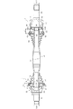
- FIG. 1 is a cross-sectional view showing an overall configuration of a vehicle rear drive shaft in an embodiment of the present invention.
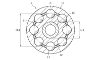
- FIG. 2 is a cross-sectional view taken along line AA in FIG.
- FIG. 3 is a sectional view taken along line BB in FIG. 1.
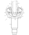
- FIG. 2 is a cross-sectional view showing a state where the operating angle of the hollow shaft is 0 ° in the fixed type constant velocity universal joint of FIG. 1. It is sectional drawing which shows the state which incorporates a ball
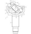
- FIG. 5 is a cross-sectional view showing a state in which the angle of the hollow shaft is restricted by a stopper structure in the fixed type constant velocity universal joint of FIG. 4.
- a Rzeppa type constant velocity universal joint which is one of fixed type constant velocity universal joints incorporated in a drive shaft for automobiles. It can also be applied to cut-free type constant velocity universal joints (UJ).
- UJ cut-free type constant velocity universal joints
- a sliding type constant velocity universal joint incorporated in a drive shaft although a double offset type constant velocity universal joint (DOJ) is illustrated, a tripod type constant velocity universal joint (TJ) may be sufficient.
- DOJ double offset type constant velocity universal joint
- TJ tripod type constant velocity universal joint
- the drive shaft for a vehicle rear in this embodiment includes a Rzeppa constant velocity universal joint 1 that allows only angular displacement on the wheel side (outboard side), and the engine side (inboard side).
- a double offset type constant velocity universal joint 5 that allows both axial displacement and angular displacement is attached to each other, and both constant velocity universal joints 1 and 5 are connected by a hollow shaft 15.
- the Rzeppa type constant velocity universal joint 1 of this embodiment includes a cup-shaped outer joint member 11, an inner joint member 12, a plurality of balls 13, and a cage 14, and extends from the inner joint member 12 to be an outer joint member.
- the hollow shaft 15 which protrudes from the opening part of 11 is couple
- the outer joint member 11 is formed with arc-shaped track grooves 16 extending in the axial direction at a plurality of positions in the circumferential direction of the spherical inner peripheral surface 17 at equal intervals.
- a stem portion 19 extends in the axial direction from the bottom portion 18 of the outer joint member 11 and is integrally formed.
- the inner joint member 12 is paired with the track groove 16 of the outer joint member 11, and arc-shaped track grooves 20 are formed at equal intervals in the circumferential direction of the spherical outer peripheral surface 21.
- the ball 13 is interposed between the track groove 16 of the outer joint member 11 and the track groove 20 of the inner joint member 12.
- the ball 13 transmits rotational torque between the outer joint member 11 and the inner joint member 12.
- the cage 14 is interposed between the inner peripheral surface 17 of the outer joint member 11 and the outer peripheral surface 21 of the inner joint member 12.
- a plurality of pockets 22 that hold the balls 13 are formed at equal intervals in a plurality of locations in the circumferential direction.
- the hollow shaft 15 has a concave hole 23 penetrating along the axial direction.
- the hollow shaft 15 is formed from a steel pipe (electrically welded pipe, seamless pipe) having a carbon content of 0.2 to 0.45% by a diameter reduction process such as a swaging process or a press drawing process. After the spline is formed, a member subjected to heat treatment such as induction hardening or carburizing and quenching.
- the hollow shaft 15 is press-fitted into the shaft hole of the inner joint member 12 and is connected so that torque can be transmitted by spline fitting.
- a step 25 is provided at the back end of the inner joint member 12, an annular concave groove 26 is formed in the shaft end 24 of the hollow shaft 15, and a retaining ring 27 fitted in the concave groove 26 is connected to the inner joint member 12.
- the hollow shaft 15 is prevented from coming off from the inner joint member 12 by being engaged with the step 25.
- the Rzeppa constant velocity universal joint used in the front drive shaft of the automobile can take an operating angle of up to 47 °
- the Rzeppa constant velocity universal joint 1 used in the rear drive shaft of the automobile has a maximum operating angle. Since the track groove between the operating angles of 20 ° to 47 ° is not required because it is as small as 20 ° or less, the track grooves 16 and 20 of the outer joint member 11 and the inner joint member 12 are made shorter than those for the front, and the outer joint member 11. The axial dimension of the inner joint member 12 can be shortened.
- the angle at which the balls 13 are assembled can be reduced and the pocket length of the cage 14 can be shortened, so that the load capacity of the cage 14 is increased. Moreover, if the maximum operating angle to be used is reduced, the variation of the load value acting on each ball 13 is reduced, and the peak load is reduced. Therefore, the ball PCD can be made smaller by the increase in the torque load capacity of the constant velocity universal joint 1, and the radial direction can be made compact.
- the load applied to one ball is smaller than when the number of balls 13 is 6, so that the ball diameter can be reduced.
- the track grooves 16 and 20 of the joint member 12 can be made shallow.
- the axial dimension of the inner joint member 12 is reduced and the number of the balls 13 is set to eight. Since the thickness of the track groove bottom portion at both ends can be increased, the PCD of the spline can be increased, and the torque load capacity of the spline fitting portion can be increased.
- the 8-ball rear Rzeppa constant velocity universal joint 1 is more compact in the axial direction and the radial direction than the front one, and the spline PCD can be made larger. Therefore, the axial dimension of the inner joint member 12 is L1, When the ball PCD is Db1 and the spline PCD of the inner joint member 12 is Ds1, L1, Db1, and Ds1 satisfy the conditions of L1 / Ds1 ⁇ 0.9 and Db1 / Ds1 ⁇ 2.1.
- the double offset type constant velocity universal joint 5 used in the rear drive shaft includes a cup-shaped outer joint member 51, an inner joint member 52, a plurality of balls 53, and a cage 54.
- the hollow shaft 15 extending from the inner joint member 52 and projecting from the opening of the outer joint member 51 is coupled.
- linear track grooves 56 extending in the axial direction are formed at equal intervals in a plurality of locations in the circumferential direction of the cylindrical inner peripheral surface 57.
- a stem portion 59 extends in the axial direction from the bottom 58 of the outer joint member 51 and is integrally formed.
- the inner joint member 52 is paired with the track groove 56 of the outer joint member 51, and linear track grooves 60 are formed at a plurality of locations in the circumferential direction of the spherical outer peripheral surface 61 at equal intervals.
- the ball 53 is interposed between the track groove 56 of the outer joint member 51 and the track groove 60 of the inner joint member 52.
- the ball 53 transmits rotational torque between the outer joint member 51 and the inner joint member 52.
- the cage 54 is interposed between the inner peripheral surface 57 of the outer joint member 51 and the outer peripheral surface 61 of the inner joint member 52.
- a plurality of pockets 62 for holding the balls 53 are formed at equal intervals in a plurality of locations in the circumferential direction.
- the double offset type constant velocity universal joint used in the front drive shaft can take an operating angle of about 25 ° to 30 °, while the double offset type constant velocity universal joint 5 used in the rear drive shaft has a maximum operating angle.
- the operating angle is limited to 20 ° or less, a track groove having an operating angle of 20 ° or more becomes unnecessary. Therefore, the track groove 60 of the inner joint member 52 is made shorter than that for the front, and the axial dimension of the inner joint member 52 is shortened. can do.
- the pocket length of the cage 54 can be shortened and the taper angle of the outer diameter is also reduced, so that the load capacity of the cage 54 is increased. Further, if the maximum operating angle to be used is reduced, the variation of the load value acting on each ball 53 is reduced, and the peak load is reduced. Therefore, the ball PCD can be made smaller by the increase in the torque load capacity of the constant velocity universal joint 5, and it can be made compact in the radial direction.
- the load applied to one ball is smaller than that when the number of balls 53 is six, so that the ball diameter can be reduced.
- the track grooves 56 and 60 of the joint member 52 can be made shallow. Thereby, since the thickness of the track groove bottom part of the inner joint member 52 can be increased, the PCD of the spline can be increased, and the torque load capacity of the spline fitting part can be increased.
- the rear double offset constant velocity universal joint 5 for eight balls is more compact in the axial direction and radial direction than the front one, and the spline PCD can be made larger, so the axial dimension of the inner joint member 52 is L2.
- the ball PCD is Db2 and the spline PCD of the inner joint member 52 is Ds2, L2, Db2, and Ds2 satisfy the conditions of L2 / Ds2 ⁇ 0.9 and Db2 / Ds2 ⁇ 2.1.
- the spline PCD can be made larger than the front spline PCD, so that the spline diameter of the hollow shaft 15 is increased.
- the thickness of the spline fitting portion can be made thinner than the front hollow shaft as much as the strength can be afforded.
- the thickness of the spline fitting part is reduced, the thickness of the steel pipe can be reduced, which not only reduces the weight, but also reduces the drawing processing load, making it easier to manufacture, material costs, processing costs Can be suppressed and the cost can be reduced. Further, as shown in FIG. 1, if the thinning process is performed on the central portion of the hollow shaft 15, the hollow shaft 15 becomes lighter.
- the eight balls are only one example, and may be six balls, and the number of balls 13 and 53 is arbitrary.
- the boot 10 of the Rzeppa constant velocity universal joint 1 is used in the rear drive shaft, it is not necessary to extend the bellows at a high operating angle.
- the number can be reduced, the outer diameter can be reduced, and the size can be reduced.
- the boot 50 of the double offset type constant velocity universal joint 5 is also used in the rear drive shaft, so that the Zepper type constant velocity universal joint 1 does not take a high operating angle as in the front.
- the sliding amount of the double offset type constant velocity universal joint 5 associated with the bending of the universal joint 1 can be reduced, and the maximum operating angle of the double offset type constant velocity universal joint 5 is set to 20 ° or less.
- the number of bellows can be reduced, the outer diameter can be reduced, and the size can be reduced.
- the balls 13 are assembled so that the 14 pockets 22 can be seen from the outer joint member 11.
- the hollow shaft 15 in a state where a plug 28 (described later) is attached to the shaft end 24 is press-fitted into the shaft hole of the inner joint member 12 and removed from the inner joint member 12 by the retaining ring 27. Stop.
- the outer joint member 11, the inner joint member 12, and the like constituting the constant velocity universal joint 1 when handling the constant velocity universal joint 1 such as when the constant velocity universal joint 1 after the ball is assembled or when being assembled to the vehicle body, the outer joint member 11, the inner joint member 12, and the like constituting the constant velocity universal joint 1, The ball 13 and the cage 14 are free. In this free state, even if the maximum operating angle when the joint is used is 20 ° or less, the constant velocity universal joint 1 may exceed the maximum operating angle due to its own weight (see FIG. 5).
- the constant velocity universal joint 1 is handled, even if the outer joint member 11, the inner joint member 12, the ball 13 and the cage 14 constituting the constant velocity universal joint 1 are free, the constant velocity universal joint is used.
- the constant velocity universal joint 1 is handled at a constant velocity.
- the following stopper structure is adopted.
- the rear Zepper type constant velocity universal joint 1 of the embodiment shown in FIG. 4 protrudes toward the shaft end 24 of the hollow shaft 15 facing the bottom 18 of the outer joint member 11 toward the bottom 18 of the outer joint member 11. It has a structure to which a plug 28 that is an angle regulating member is attached.
- the constant velocity universal joint 1 has a structure in which a concave portion 29 is formed in the bottom portion 18 of the outer joint member 11 and the distal end portion 30 of the plug 28 is inserted into the concave portion 29.
- the plug is plugged at an angle smaller than the angle at which the ball 13 is assembled and larger than the maximum operating angle when the joint is used.
- the distal end portion 30 of the outer joint member 11 can interfere with the peripheral portion 31 of the concave portion 29 of the outer joint member 11.
- the concave portion 29 of the outer joint member 11 has a bowl shape in which the depth gradually decreases from the flat surface at the shaft center toward the radially outer side. That is, the concave portion 29 has an angle smaller than the maximum operating angle when the joint is used, and has a shape in which the distal end portion 30 of the plug 28 does not interfere with a portion other than the peripheral portion 31.
- the recess 29 can be formed by cutting the bottom 18 of the outer joint member 11, but can also be simultaneously formed by forging the outer joint member 11. In this case, processing man-hours and costs can be reduced.
- the plug 28 is composed of a bottomed cylindrical member formed by pressing.
- the plug 28 is press-fitted into the concave hole 23 of the hollow shaft 15 by setting its outer diameter to be slightly larger than the inner diameter of the concave hole 23 of the hollow shaft 15.
- the plug 28 is press-fitted into the concave hole 23 of the hollow shaft 15, but other mounting structures may be used.
- the plug 28 may be fixed to the concave hole 23 of the hollow shaft 15 with an adhesive by setting the outer diameter of the plug 28 to be equal to the inner diameter of the concave hole 23 of the hollow shaft 15.
- the plug 28 exhibits a stopper function between the outer joint member 11 and the concave portion 29, but closes the concave hole 23 opened at the shaft end 24 of the hollow shaft 15. From this, the plug 28 is provided with a lubricant such as grease sealed inside the outer joint member 11 by the boot 10 (see FIG. 1) mounted between the outer joint member 11 and the hollow shaft 15. It has a function of preventing leakage from the inside of the joint member 11 to the inside of the hollow shaft 15.
- the plug 68 is press-fitted into the concave hole 23 of the hollow shaft 15, and the concave hole 23 opened at the shaft end of the hollow shaft 15 is closed by the plug 68.
- a lubricant such as grease sealed inside the outer joint member 51 by the boot 50 mounted between the outer joint member 51 and the hollow shaft 15 is transferred from the inside of the outer joint member 51 to the hollow shaft 15. It has a function to prevent leakage into the interior of the machine.
- the stopper structure constituted by the plug 28 of the hollow shaft 15 and the concave portion 29 of the outer joint member 11 is used to transport the constant velocity universal joint 1 and to the vehicle body.
- the distal end portion 30 of the plug 28 comes into contact with the peripheral portion 31 of the concave hole 29, and the plug 28 interferes with the bottom portion 18 of the outer joint member 11.
- the plug 28 exhibits a stopper function that restricts the operating angle of the hollow shaft 15 to an angle ⁇ 2 that is smaller than the angle ⁇ 1 at which the ball 13 drops off due to interference with the peripheral portion 31 of the recess 29. .
- ⁇ 2 that is smaller than the angle ⁇ 1 at which the ball 13 drops off due to interference with the peripheral portion 31 of the recess 29.
- the angle at which the plug 28 of the hollow shaft 15 interferes with the peripheral portion 31 of the recess 29 is smaller than the angle of incorporation of the ball 13 and larger than the maximum operating angle when using the joint, the aforementioned ⁇ 2
- the shaft end 24 of the hollow shaft 15 is extended as in the prior art. Therefore, the constant velocity universal joint 1 can be reduced in weight. Moreover, since it is not necessary to provide a protrusion on the hollow shaft 15, the material diameter of the hollow shaft 15 can be reduced, and the cost of the constant velocity universal joint 1 can be reduced.
- FIG. 7 shows a state in which the hollow shaft 15 is angle-controlled by the stopper structure, and the same parts as those in FIG.
- the ring-shaped member 32 is fitted to the bottom 18 of the outer joint member 11, and the hollow shaft 15 is fitted to the inner peripheral portion 33 of the ring-shaped member 32.
- a stopper structure that enables the plug 28 to interfere is provided.
- the ring-shaped member 32 is fitted to the peripheral portion of the recess 29 of the outer joint member 11 so as to protrude toward the hollow shaft along the axial direction.
- the ring-shaped member 32 protrudes toward the hollow shaft side, the axial position of the peripheral portion 33 where the plug 28 of the hollow shaft 15 interferes is more hollow than in the case of the constant velocity universal joint 1 of FIG. Close to the side. As a result, the protruding amount L of the plug 28 with respect to the hollow shaft 15 can be reduced.
- the concave portion 29 of the outer joint member 11 can also be reduced, the wall thickness t (axial dimension) of the bottom 18 of the outer joint member 11 can be increased. As a result, it becomes easy to ensure the strength at the bottom 18 of the outer joint member 11.
- the bottomed cylindrical plug 28 having the same diameter is exemplified.
- the inner diameter of the concave hole 23 of the hollow shaft 15 is equal to the constant velocity universal joint of FIG.
- the stopper structure having the embedding plug 34 as described below is suitable.
- the bottomed cylindrical portion 35 is press-fitted into the concave hole 23 of the hollow shaft 15, and the enlarged diameter portion 36 can interfere with the concave portion 29 of the outer joint member 11.
- the diameter-expanded portion 36 of the plug 34 is made to interfere with the peripheral portion 31 of the concave portion 29 of the outer joint member 11, so that when the constant velocity universal joint 1 is handled, It becomes possible to restrict the operating angle to an angle ⁇ 2 that is smaller than the angle ⁇ 1 at which the ball 13 drops and larger than the maximum operating angle when the joint is used.
- the plugs 28 and 34 may have any strength as long as they can reliably regulate the angle of the hollow shaft 15 without being deformed upon interference with the concave portion 29 or the ring-shaped member 32 of the outer joint member 11, such as steel and aluminum. Either metal or resin such as reinforced plastic may be used. Considering weight reduction of the constant velocity universal joint 1, a lightweight resin is effective.
- FIG. 9 When a resin plug is used, a stopper structure in which a plug 37 having a shape as shown in FIG. 9 is fitted in the concave hole 23 of the hollow shaft 15 is possible.
- FIG. 9 the same parts as those in FIG.
- the plug 37 includes a cylindrical portion 38 that extends along the axial center of the hollow shaft 15, a plurality of flange portions 39 that are integrally formed at the base end portion of the cylindrical portion 38, and the cylindrical portion 38. And a flange portion 40 formed integrally with the front end portion of the.
- the flange portion 39 is press-fitted into the concave hole 23 of the hollow shaft 15, and the flange portion 40 can interfere with the concave portion 29 of the outer joint member 11.
- what is necessary is just to determine the number of the collar parts 39 suitably according to fitting strength.
- the flange portion 40 of the plug 37 is interfered with the peripheral portion 31 of the concave portion 29 of the outer joint member 11, so that the operation of the hollow shaft 15 is handled when the constant velocity universal joint 1 is handled. It becomes possible to restrict the angle to an angle ⁇ 2 that is smaller than the angle ⁇ 1 at which the ball 13 drops and larger than the maximum operating angle when the joint is used.
- the hollow shaft 15 having the recessed hole 23 penetrating in the axial direction is illustrated, but even a solid shaft in which a recessed portion to which the plugs 28, 34, and 37 can be attached is formed at the shaft end portion. Good.
- a stopper structure having a pin-like member 41 that is an angle regulating member having a structure as shown in FIG. 10 is possible.
- an attachment hole 44 is provided in the shaft end portion 43 of the solid shaft 42, and the pin-like member 40 is attached to the attachment hole 39. If the center hole at the time of processing the solid shaft 42 is used as it is as the mounting hole 44, the cost can be reduced without increasing the number of processing steps.
- the solid shaft 42 of the solid shaft 42 is handled during handling of the constant velocity universal joint 1 by causing the tip of the pin-shaped member 41 to interfere with the peripheral portion 31 of the recess 29 of the outer joint member 11.
Landscapes
- Engineering & Computer Science (AREA)
- General Engineering & Computer Science (AREA)
- Mechanical Engineering (AREA)
- Shafts, Cranks, Connecting Bars, And Related Bearings (AREA)
Abstract
本発明は、カップ状の外側継手部材(11)と、その外側継手部材(11)に収容され、外側継手部材(11)との間でボール(13)を介して角度変位を許容しながらトルクを伝達する内側継手部材(12)とを備え、内側継手部材(12)にシャフト(15)をトルク伝達可能に結合させた固定式等速自在継手であって、外側継手部材(11)の底部(18)に凹部(29)を設け、その凹部(29)と対向するシャフト(15)の軸端部(24)に、外側継手部材(11)の凹部(29)に入り込んだ埋め栓(28)を取り付け、その埋め栓(28)は、ボール(13)の組み込み角度より小さく、かつ、継手使用時の最大作動角よりも大きな角度で、外側継手部材(11)の凹部(29)と干渉可能とした固定式等速自在継手に関する。
Description
本発明は、自動車や各種産業機械の動力伝達系に使用され、特に自動車リア用ドライブシャフトや自動車用プロペラシャフトに組み込まれる固定式等速自在継手に関する。
自動車のエンジンから車輪に回転力を等速で伝達する手段として使用される等速自在継手には、固定式等速自在継手と摺動式等速自在継手の二種がある。これら両者の等速自在継手は、駆動側と従動側の二軸を連結してその二軸が作動角をとっても等速で回転トルクを伝達し得る構造を備えている。
自動車のエンジンから車輪に動力を伝達するドライブシャフトは、エンジンと車輪との相対的位置関係の変化による角度変位と軸方向変位に対応する必要がある。そのため、ドライブシャフトは、一般的に、エンジン側(インボード側)に軸方向変位および角度変位の両方を許容する摺動式等速自在継手を、車輪側(アウトボード側)に角度変位のみを許容する固定式等速自在継手をそれぞれ装備し、両者の等速自在継手をシャフトで連結した構造を具備する。
前述した固定式等速自在継手は、軸方向変位を許容できないが大きな作動角(最大作動角45°以上)を許容することができる点で、主に自動車フロント用ドライブシャフトの車輪側に適用される。
一方、この固定式等速自在継手は、自動車リア用ドライブシャフトの車輪側や自動車用プロペラシャフトに適用される場合もある。その場合、自動車フロント用のように最大作動角を45°以上とする必要がなく、自動車リア用であれば、最大作動角が20°以下、プロペラシャフト用であれば、最大作動角が10°以下である。
このように、自動車リア用ドライブシャフトでは、最大作動角が20°以下と小さいことから、等速自在継手の軽量化およびコスト低減を目的として、自動車フロント用ドライブシャフトで使用される外側継手部材よりもトラック溝を短くして軸方向寸法を小さくした外側継手部材を使用している。
ここで、フロント用等速自在継手の組み立て時には、最大作動角以上の角度をとった状態で、ボールを組み込む。シャフトの組み付け後は、シャフトと外側継手部材とがボールが組み込める角度より低い角度で干渉するため、ボールが外側継手部材のトラック溝から外れて脱落することを防止している。
しかしながら、前述したように、軸方向寸法が小さい外側継手部材を持つ自動車リア用ドライブシャフトに使用される等速自在継手では、作動角を大きくとると、シャフトが外側継手部材と干渉する前にボールが脱落する角度を超える状態となり、ボールが外側継手部材のトラック溝から外れて脱落してしまう。
そこで、等速自在継手の取り扱い時、外側継手部材のトラック溝からボールが外れて脱落することを未然に防止する手段を設けた等速自在継手が種々提案されている(例えば、特許文献1,2参照)。
ところで、等速自在継手の取り扱い時、外側継手部材のトラック溝からボールが外れて脱落することを未然に防止する手段を設けた特許文献1,2の等速自在継手は、以下のような構造および課題を持つ。
特許文献1で開示された等速自在継手は、内側継手部材に嵌合されたシャフトの軸端部を延在させ、そのシャフトの延在部を外側継手部材の底部に当接可能としたストッパ構造を具備する。
この等速自在継手では、外側継手部材に対してシャフトが最大作動角より大きな作動角をとった時、シャフトの延在部が外側継手部材の底部と干渉することにより、ボールが外側継手部材のトラック溝から外れて脱落することを未然に防止している。
しかしながら、この特許文献1の等速自在継手の場合、シャフトの軸端部が必要以上に長くなり、その分、シャフトの重量増加を招くことになる。このように、シャフトの重量増加により、等速自在継手の軽量化を困難なものにしている。
特許文献2で開示された等速自在継手は、内側継手部材に嵌合されたシャフトの外側継手部材の開口部近傍部位に突起を設け、その突起を外側継手部材の開口端部に当接可能としたストッパ構造を具備する。
この等速自在継手では、外側継手部材に対してシャフトが最大作動角より大きな作動角をとった時、シャフトの突起が外側継手部材の開口端部と干渉することにより、ボールが外側継手部材のトラック溝から外れて脱落することを未然に防止している。
しかしながら、この特許文献2の等速自在継手の場合、シャフトに突起を形成するため、シャフトを切削加工する前の素材径を大きくする必要がある。その結果、突起を形成するためのシャフトの切削加工が必要であり、また、シャフトの素材に大径のものが必要であることから、切削加工費や材料費の面で、等速自在継手のコスト低減を困難なものにしている。
そこで、本発明は前述の課題に鑑みて提案されたもので、その目的とするところは、等速自在継手の取り扱い時、ボールが外側継手部材から脱落することを防止すると共に、等速自在継手の軽量化およびコスト低減を容易に図ることにある。
本発明に係る固定式等速自在継手は、カップ状の外側継手部材と、その外側継手部材に収容され、外側継手部材との間でボールを介して角度変位を許容しながらトルクを伝達する内側継手部材とを備え、その内側継手部材にシャフトをトルク伝達可能に結合させた構造を具備する。
前述の目的を達成するための技術的手段として、本発明は、外側継手部材の底部と対向するシャフトの軸端部に、外側継手部材の底部に向けて突出する角度規制部材を取り付け、角度規制部材は、ボールの組み込み角度より小さく、かつ、継手使用時の最大作動角よりも大きな角度で、外側継手部材の底部と干渉可能としたことを特徴とする。
本発明では、外側継手部材の底部に向けて突出する角度規制部材を、外側継手部材の底部と対向するシャフトの軸端部に取り付けたことにより、等速自在継手の取り扱い時、ボールの組み込み角度よりも小さい角度、つまり、ボールが脱落する角度より小さな角度で、シャフトの角度規制部材が外側継手部材の底部と干渉する。これにより、ボールが外側継手部材から外れて脱落することを未然に防止できる。
このように、角度規制部材は、等速自在継手の取り扱い時、外側継手部材の底部との干渉により、シャフトの作動角を規制するストッパ機能を発揮する。一方、継手使用時の最大作動角以下の作動角では、角度規制部材が外側継手部材の底部と干渉することはない。これにより、車体などに組み付けられた等速自在継手が必要とする作動角をとることが可能となる。
以上のように、シャフトの角度規制部材と外側継手部材の底部との干渉によりシャフトの作動角を規制するため、従来のように、シャフトの軸端部を延在させる必要がないので、等速自在継手の軽量化が図れる。また、シャフトに突起を設ける必要がないので、シャフトの素材径を小さくすることができ、等速自在継手のコスト低減が図れる。
本発明において、外側継手部材の底部に凹部を形成し、その凹部に入り込んだ角度規制部材は、外側継手部材の凹部と干渉可能とした構造が望ましい。このような構造を採用すれば、等速自在継手の取り扱い時、ボールが脱落する角度より小さな角度で、角度規制部材を外側継手部材の凹部と確実に干渉させることができる。ここで、外側継手部材の底部に凹部を設けたことにより、継手使用時の最大作動角以下の作動角では、角度規制部材が外側継手部材の底部と確実に干渉しないようにすることができる。
本発明において、シャフトは、軸方向に貫通する凹孔を有する中空シャフトとし、角度規制部材は、中空シャフトの軸端部で開口する凹孔を閉塞する埋め栓とした構造が望ましい。このような構造を採用すれば、中空シャフトを使用することで、等速自在継手の軽量化をより一層容易に実現することができる。また、外側継手部材の内部に封入された潤滑剤が中空シャフト内に流入することを阻止する埋め栓がストッパ機能を発揮する。
本発明によれば、等速自在継手の取り扱い時、ボールが脱落する角度より小さな角度で、シャフトの角度規制部材が外側継手部材の底部と干渉することにより、ボールが外側継手部材から外れて脱落することを未然に防止できる。このように、シャフトの軸端部に取り付けられた角度規制部材と外側継手部材の底部との干渉によるストッパ構造により、等速自在継手の軽量化およびコスト低減が図れる。
本発明に係る固定式等速自在継手の実施形態を図面に基づいて以下に詳述する。
以下の実施形態では、例えば、自動車用ドライブシャフトに組み込まれる固定式等速自在継手の一つであるツェッパ型等速自在継手(BJ)を例示するが、他の固定式等速自在継手としてアンダーカットフリー型等速自在継手(UJ)にも適用可能である。また、ドライブシャフトに組み込まれる摺動式等速自在継手としては、ダブルオフセット型等速自在継手(DOJ)を例示するが、トリポード型等速自在継手(TJ)であってもよい。
自動車のエンジンから車輪に動力を伝達するドライブシャフトは、エンジンと車輪との相対的位置関係の変化による角度変位と軸方向変位に対応する必要がある。そのため、この実施形態における自動車リア用ドライブシャフトは、図1に示すように、車輪側(アウトボード側)に角度変位のみを許容するツェッパ型等速自在継手1を、エンジン側(インボード側)に軸方向変位および角度変位の両方を許容するダブルオフセット型等速自在継手5をそれぞれ装着し、両者の等速自在継手1,5を中空シャフト15で連結した構造を具備する。
この実施形態のツェッパ型等速自在継手1は、カップ状の外側継手部材11と、内側継手部材12と、複数のボール13と、ケージ14とを備え、内側継手部材12から延びて外側継手部材11の開口部から突出する中空シャフト15が結合されている。
外側継手部材11は、図4に示すように、軸方向に延びる円弧状トラック溝16が球面状内周面17の円周方向複数箇所に等間隔で形成されている。また、外側継手部材11の底部18からステム部19が軸方向に延びて一体に形成されている。内側継手部材12は、外側継手部材11のトラック溝16と対をなして円弧状トラック溝20が球面状外周面21の円周方向複数箇所に等間隔で形成されている。
ボール13は、外側継手部材11のトラック溝16と内側継手部材12のトラック溝20との間に介在する。このボール13は、外側継手部材11と内側継手部材12との間で回転トルクを伝達する。ケージ14は、外側継手部材11の内周面17と内側継手部材12の外周面21との間に介在する。このケージ14は、ボール13を保持する複数のポケット22が円周方向複数箇所に等間隔で形成されている。
中空シャフト15は、軸方向に沿って貫通する凹孔23を有する。中空シャフト15は、炭素量0.2~0.45%の鋼管(電縫管、シームレス管)を素材として、スウェージング加工またはプレス絞り加工などの縮径加工で成形し、その軸端部24にスプラインを形成した後、高周波焼入れまたは浸炭焼入れなどの熱処理を施した部材である。
この中空シャフト15は、内側継手部材12の軸孔に圧入されてスプライン嵌合によりトルク伝達可能に連結されている。内側継手部材12の奥側端部に段差25を設けると共に中空シャフト15の軸端部24に環状の凹溝26を形成し、その凹溝26に嵌合された止め輪27を内側継手部材12の段差25に係止させることで、中空シャフト15が内側継手部材12に対して抜け止めされている。
以上の構成からなるツェッパ型等速自在継手1では、中空シャフト15により外側継手部材11と内側継手部材12との間に作動角が付与されると、ケージ14に保持されたボール13は常にどの作動角においても、その作動角の二等分面内に維持され、外側継手部材11と内側継手部材12との間での等速性が確保される。外側継手部材11と内側継手部材12との間では、等速性が確保された状態で回転トルクがボール13を介して伝達される。
自動車フロント用ドライブシャフトで使用されるツェッパ型等速自在継手が47°まで作動角をとれるのに対して、自動車リア用ドライブシャフトで使用されるツェッパ型等速自在継手1は、最大作動角が20°以下と小さいことから、作動角20°~47°間のトラック溝が不要となるため、外側継手部材11、内側継手部材12のトラック溝16,20をフロント用より短くし、外側継手部材11、内側継手部材12の軸方向寸法を短縮することができる。
外側継手部材11、内側継手部材12の軸方向寸法が小さくなると、ボール13の組み込み角度も小さくでき、ケージ14のポケット長さも短くできるため、ケージ14の負荷容量が上がる。また、使用する最大作動角が小さくなれば、各ボール13に働く荷重値の変動が小さくなり、ピーク荷重が低下する。従って、等速自在継手1のトルク負荷容量が上がった分、ボールPCDを小さくし、径方向へのコンパクト化が可能となる。
ボール13の個数を8個とすれば(図2参照)、6個のときと比べて、ボール1個にかかる荷重が小さくなるため、ボール径を小さくすることができ、外側継手部材11、内側継手部材12のトラック溝16,20を浅くすることができる。
このように、リア用ドライブシャフトで使用されるツェッパ型等速自在継手1では、内側継手部材12の軸方向寸法を小さくし、ボール13の個数を8個とすることで、内側継手部材12の両端部のトラック溝底部の肉厚を厚くできるため、スプラインのPCDを大きくし、スプライン嵌合部のトルク負荷容量を上げることができる。
また、8個ボールのリア用ツェッパ型等速自在継手1は、フロント用と比べて、軸方向および径方向にコンパクトとなり、スプラインPCDが大きく取れるため、内側継手部材12の軸方向寸法をL1、ボールPCDをDb1、内側継手部材12のスプラインPCDをDs1としたとき、L1,Db1,Ds1は、L1/Ds1≦0.9、およびDb1/Ds1≦2.1の条件を満足する。
一方、リア用ドライブシャフトで使用されるダブルオフセット型等速自在継手5は、図1に示すように、カップ状の外側継手部材51と、内側継手部材52と、複数のボール53と、ケージ54とを備え、内側継手部材52から延びて外側継手部材51の開口部から突出する中空シャフト15が結合されている。
外側継手部材51は、軸方向に延びる直線状トラック溝56が円筒状内周面57の円周方向複数箇所に等間隔で形成されている。また、外側継手部材51の底部58からステム部59が軸方向に延びて一体に形成されている。内側継手部材52は、外側継手部材51のトラック溝56と対をなして直線状トラック溝60が球面状外周面61の円周方向複数箇所に等間隔で形成されている。
ボール53は、外側継手部材51のトラック溝56と内側継手部材52のトラック溝60との間に介在する。このボール53は、外側継手部材51と内側継手部材52との間で回転トルクを伝達する。ケージ54は、外側継手部材51の内周面57と内側継手部材52の外周面61との間に介在する。このケージ54は、ボール53を保持する複数のポケット62が円周方向複数箇所に等間隔で形成されている。
フロント用ドライブシャフトで使用されるダブルオフセット型等速自在継手が25°~30°程度まで作動角をとれるのに対し、リア用ドライブシャフトで使用されるダブルオフセット型等速自在継手5では、最大作動角を20°以下に制限した場合、作動角20°以上のトラック溝が不要となるため、内側継手部材52のトラック溝60をフロント用より短くし、内側継手部材52の軸方向寸法を短縮することができる。
使用する最大作動角が小さくなると、ケージ54のポケット長さを短くでき、その外径のテーパ角も小さくなるため、ケージ54の負荷容量が上がる。また、使用する最大作動角が小さくなれば、各ボール53に働く荷重値の変動が小さくなり、ピーク荷重が低下する。従って、等速自在継手5のトルク負荷容量が上がった分、ボールPCDを小さくし、径方向へのコンパクト化が可能となる。
ボール53の個数を8個とすれば(図3参照)、6個のときと比べて、ボール1個にかかる荷重が小さくなるため、ボール径を小さくすることができ、外側継手部材51、内側継手部材52のトラック溝56,60を浅くすることができる。これにより、内側継手部材52のトラック溝底部の肉厚を厚くできるため、スプラインのPCDを大きくし、スプライン嵌合部のトルク負荷容量を上げることができる。
また、8個ボールのリア用ダブルオフセット型等速自在継手5は、フロント用と比べて、軸方向および径方向にコンパクトとなり、スプラインPCDが大きく取れるため、内側継手部材52の軸方向寸法をL2、ボールPCDをDb2、内側継手部材52のスプラインPCDをDs2としたとき、L2,Db2,Ds2は、L2/Ds2≦0.9、およびDb2/Ds2≦2.1の条件を満足する。
リア用ドライブシャフトに前述のツェッパ型等速自在継手1とダブルオフセット型等速自在継手5を適用した場合、スプラインPCDを、フロント用のスプラインPCDより大きくできるため、中空シャフト15のスプライン径を大きくでき、強度に余裕ができる分スプライン嵌合部の肉厚をフロント用の中空シャフトより薄肉化することができる。
スプライン嵌合部の肉厚が薄くなれば、鋼管の肉厚も薄くすることができ、軽量化だけでなく、絞り加工の加工負荷も低減し、製作し易いものになり、材料費、加工費が抑えられ、コストを低減できる。さらに、図1に示すように、中空シャフト15の中央部に薄肉化の加工を施せば、さらに軽量な中空シャフト15となる。なお、8個ボールは一つの例示であり、6個ボールであってもよく、ボール13,53の個数については任意である。
ここで、ツェッパ型等速自在継手1のブーツ10は、リア用ドライブシャフトで使用することで、高作動角時の蛇腹の伸びが不要となるため、リア・フロント共用で使用するブーツより、蛇腹の数を減らし、外径も小さくし、コンパクト化することができる。
また、ダブルオフセット型等速自在継手5のブーツ50も、リア用ドライブシャフトで使用することで、フロント用のようにツェッパ型等速自在継手1が高作動角をとらないため、ツェッパ型等速自在継手1の折り曲げに伴うダブルオフセット型等速自在継手5のスライド量を小さくでき、かつ、ダブルオフセット型等速自在継手5の最大作動角も最大20°以下としたので、リア・フロント共用のブーツより、蛇腹の数を減らし、外径も小さくし、コンパクト化することができる。
一方、図4に示すリア用のツェッパ型等速自在継手1の組み立て時には、図5に示すように、最大作動角以上の角度θ1(例えばθ1=46°)をとった状態で、ケージ14のポケット22が外側継手部材11から見える位置にしてボール13の組み込みが行われる。このボール13の組み込み後、後述の埋め栓28を軸端部24に装着した状態の中空シャフト15を、内側継手部材12の軸孔に圧入して内側継手部材12に対して止め輪27で抜け止めする。
ここで、ボール組み込み後の等速自在継手1の搬送時や車体への組み付け時など、等速自在継手1の取り扱い時、等速自在継手1を構成する外側継手部材11、内側継手部材12、ボール13およびケージ14がフリーな状態となる。このフリーな状態では、継手使用時の最大作動角が20°以下であっても、構成部品の自重で等速自在継手1が最大作動角を超える状態となる場合がある(図5参照)。
このように、等速自在継手1の取り扱い時、その等速自在継手1を構成する外側継手部材11、内側継手部材12、ボール13およびケージ14がフリーな状態であっても、等速自在継手が最大作動角を超える状態となってボール13が外側継手部材11のトラック溝16から外れて脱落することを未然に防止する手段として、この実施形態では、等速自在継手1の取り扱い時に等速自在継手1の作動角を規制するため、以下のようなストッパ構造を採用している。
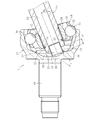
図4に示す実施形態のリア用ツェッパ型等速自在継手1は、外側継手部材11の底部18と対向する中空シャフト15の軸端部24に、外側継手部材11の底部18に向けて突出する角度規制部材である埋め栓28を取り付けた構造を具備する。一方、この等速自在継手1は、外側継手部材11の底部18に凹部29を形成し、その凹部29に埋め栓28の先端部30が入り込んだ構造を具備する。
この中空シャフト15の埋め栓28と外側継手部材11の凹部29とで構成されたストッパ構造では、ボール13の組み込み角度より小さく、かつ、継手使用時の最大作動角よりも大きな角度で、埋め栓28の先端部30が外側継手部材11の凹部29の周縁部位31と干渉可能としている。
外側継手部材11の凹部29は、軸中心の平坦面から径方向外側へ向けて深さが漸減するような擂り鉢形状をなす。つまり、凹部29は、継手使用時の最大作動角より小さな角度で、埋め栓28の先端部30が周縁部位31以外の部位で干渉しない形状をなす。
この凹部29は、外側継手部材11の底部18を切削加工することで成形可能であるが、外側継手部材11の鍛造加工により同時成形することも可能である。この場合、加工工数の削減およびコスト低減が図れる。
埋め栓28は、プレス加工により成形された有底筒状部材で構成されている。この埋め栓28は、その外径を中空シャフト15の凹孔23の内径よりも若干大きめに設定することにより中空シャフト15の凹孔23に圧入されている。
この実施形態では、埋め栓28を中空シャフト15の凹孔23に圧入しているが、他の取り付け構造であってもよい。例えば、埋め栓28の外径を中空シャフト15の凹孔23の内径と同等に設定することにより、埋め栓28を中空シャフト15の凹孔23に接着剤で固定してもよい。
埋め栓28は、外側継手部材11の凹部29との間でストッパ機能を発揮するが、中空シャフト15の軸端部24で開口する凹孔23を閉塞する。このことから、埋め栓28は、外側継手部材11と中空シャフト15との間に装着されるブーツ10(図1参照)により外側継手部材11の内部に封入されたグリース等の潤滑剤が、外側継手部材11の内部から中空シャフト15の内部へ漏洩することを防止する機能を有する。
なお、等速自在継手5(図1参照)においても、埋め栓68を中空シャフト15の凹孔23に圧入し、埋め栓68により、中空シャフト15の軸端部で開口する凹孔23を閉塞する。埋め栓68は、外側継手部材51と中空シャフト15との間に装着されるブーツ50により外側継手部材51の内部に封入されたグリース等の潤滑剤が、外側継手部材51の内部から中空シャフト15の内部へ漏洩することを防止する機能を有する。
図4に示すリア用ツェッパ型等速自在継手1では、中空シャフト15の埋め栓28と外側継手部材11の凹部29とで構成されたストッパ構造により、等速自在継手1の搬送時や車体への組み付け時のような等速自在継手1の取り扱い時、図6に示すように、ボール13の組み込み角度θ1(図5参照)、つまり、ボール13が脱落する角度より小さな角度θ2(例えばθ2=22°)で、埋め栓28の先端部30が凹孔29の周縁部位31に当接し、埋め栓28が外側継手部材11の底部18と干渉する。
このようにして、埋め栓28は、凹部29の周縁部位31との干渉により、中空シャフト15の作動角を、ボール13が脱落する角度θ1より小さな角度θ2に規制するストッパ機能を発揮する。その結果、等速自在継手1の取り扱い時にボール13が外側継手部材11のトラック溝16から外れて脱落することを未然に防止できる。
また、中空シャフト15の埋め栓28が凹部29の周縁部位31と干渉する角度は、継手使用時の最大作動角(例えば20°以下)よりも大きな角度θ2(θ2=22°)に設定されていることから、等速自在継手1の取り扱い後、車体に組み付けられた等速自在継手1が必要とする作動角をとることが可能である。
この中空シャフト15の埋め栓28が凹部29の周縁部位31と干渉する角度は、ボール13の組み込み角度より小さく、かつ、継手使用時の最大作動角よりも大きな角度であれば、前述のθ2(=22°)以外の角度であってもよい。この角度は、凹部29の径および位置、埋め栓28の外径および位置などによって調整することが可能である。
以上のように、中空シャフト15の埋め栓28と外側継手部材11の凹部29との干渉により中空シャフト15の作動角を規制するため、従来のように、中空シャフト15の軸端部24を延在させる必要がないので、等速自在継手1の軽量化が図れる。また、中空シャフト15に突起を設ける必要がないので、中空シャフト15の素材径を小さくすることができ、等速自在継手1のコスト低減が図れる。
この実施形態では、軽量な埋め栓28を中空シャフト15の軸端部24に取り付けた構造を採用していることから、等速自在継手1の重量増を抑制することができる。さらに、中空シャフト15を使用することにより、等速自在継手1の軽量化がより一層図れる。
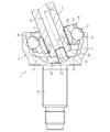
以上の実施形態では、中空シャフト15の埋め栓28を外側継手部材11の凹部29の周縁部位31と干渉可能にした構造について説明したが、本発明はこれに限定されることなく、例えば、図7に示す構造であってもよい。なお、図7は、中空シャフト15がストッパ構造により角度規制された状態を示し、図6と同一部分には同一参照符号を付して重複説明は省略する。
この実施形態の等速自在継手1は、図7に示すように、外側継手部材11の底部18にリング状部材32を嵌合させ、そのリング状部材32の内周部位33に中空シャフト15の埋め栓28を干渉可能としたストッパ構造を具備する。このリング状部材32は、軸方向に沿って中空シャフト側へ出っ張るように外側継手部材11の凹部29の周縁部位に嵌合されている。
このように、リング状部材32が中空シャフト側へ出っ張ることから、中空シャフト15の埋め栓28が干渉する周縁部位33の軸方向位置が、図6の等速自在継手1の場合よりも中空シャフト側に近接する。その結果、中空シャフト15に対する埋め栓28の突出量Lを小さくすることができる。
このことから、外側継手部材11の凹部29も小さくすることができるので、外側継手部材11の底部18の肉厚t(軸方向寸法)を大きくすることができる。その結果、外側継手部材11の底部18における強度を確保することが容易となる。
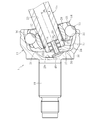
また、以上の実施形態では、同一径を有する有底筒状の埋め栓28を例示したが、図8に示すように、中空シャフト15の凹孔23の内径が、図6の等速自在継手1の場合よりも小さい場合には、以下のような埋め栓34を有するストッパ構造が好適である。図8において、図6と同一部分には同一参照符号を付して重複説明は省略する。
図8に示す埋め栓34は、有底筒状部35と、その有底筒状部35の先端部に一体的に形成された拡径部36とで構成されている。この埋め栓34では、有底筒状部35を中空シャフト15の凹孔23に圧入し、拡径部36を外側継手部材11の凹部29と干渉可能にしている。
この実施形態の等速自在継手1では、埋め栓34の拡径部36を外側継手部材11の凹部29の周縁部位31に干渉させることにより、等速自在継手1の取り扱い時、中空シャフト15の作動角を、ボール13が脱落する角度θ1より小さく、かつ、継手使用時の最大作動角よりも大きな角度θ2に規制することが可能となる。
なお、図示しないが、中空シャフト15の凹孔23の内径が、図3の等速自在継手1の場合よりも大きい場合には、逆に、有底筒状部の先端に縮径部が一体的に形成された埋め栓を有するストッパ構造が好適である。
埋め栓28,34は、外側継手部材11の凹部29あるいはリング状部材32との干渉時に変形せずに中空シャフト15の角度規制を確実に行える強度を有するものであればよく、鋼やアルミニウム等の金属製あるいは強化プラスチック等の樹脂製のいずれであってもよい。等速自在継手1の軽量化を考慮した場合、軽量な樹脂製が有効である。
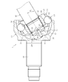
樹脂製の埋め栓を使用する場合には、図9に示すような形状を有する埋め栓37を中空シャフト15の凹孔23に嵌合させたストッパ構造が可能である。図9において、図6と同一部分には同一参照符号を付して重複説明は省略する。
この実施形態の埋め栓37は、中空シャフト15の軸中心に沿う筒状部38と、その筒状部38の基端部に一体的に形成された複数の鍔部39と、筒状部38の先端部に一体的に形成されたフランジ部40とで構成されている。この埋め栓37では、鍔部39を中空シャフト15の凹孔23に圧入し、フランジ部40を外側継手部材11の凹部29と干渉可能にしている。なお、鍔部39の数は嵌合強度に応じて適宜決めればよい。
この実施形態の等速自在継手1では、埋め栓37のフランジ部40を外側継手部材11の凹部29の周縁部位31に干渉させることにより、等速自在継手1の取り扱い時、中空シャフト15の作動角を、ボール13が脱落する角度θ1より小さく、かつ、継手使用時の最大作動角よりも大きな角度θ2に規制することが可能となる。
以上の実施形態では、軸方向に貫通する凹孔23を有する中空シャフト15を例示したが、埋め栓28,34,37が取り付け可能な凹部を軸端部に形成した中実シャフトであってもよい。また、中実シャフトの場合、図10に示すような構造の角度規制部材であるピン状部材41を持つストッパ構造が可能である。
このストッパ構造では、中実シャフト42の軸端部43に取り付け孔44を設け、この取り付け孔39にピン状部材40を取り付けている。この取り付け孔44は、中実シャフト42の加工時のセンター孔をそのまま利用すれば、加工工程を増やすことなく、コスト低減が図れる。
この実施形態の等速自在継手1では、ピン状部材41の先端部を外側継手部材11の凹部29の周縁部位31に干渉させることにより、等速自在継手1の取り扱い時、中実シャフト42の作動角を、ボール13が脱落する角度θ1より小さく、かつ、継手使用時の最大作動角よりも大きな角度θ3(θ3=31°)に規制することが可能となる。
本発明は前述した実施形態に何ら限定されるものではなく、本発明の要旨を逸脱しない範囲内において、さらに種々なる形態で実施し得ることは勿論のことであり、本発明の範囲は、請求の範囲によって示され、さらに請求の範囲に記載の均等の意味、および範囲内のすべての変更を含む。
Claims (3)
- カップ状の外側継手部材と、前記外側継手部材に収容され、外側継手部材との間でボールを介して角度変位を許容しながらトルクを伝達する内側継手部材とを備え、前記内側継手部材にシャフトをトルク伝達可能に結合させた固定式等速自在継手であって、
前記外側継手部材の底部と対向する前記シャフトの軸端部に、外側継手部材の底部に向けて突出する角度規制部材を取り付け、前記角度規制部材は、前記ボールの組み込み角度より小さく、かつ、継手使用時の最大作動角よりも大きな角度で、外側継手部材の底部と干渉可能としたことを特徴とする固定式等速自在継手。 - 前記外側継手部材の底部に凹部を形成し、前記凹部に入り込んだ前記角度規制部材は、外側継手部材の凹部と干渉可能とした請求項1に記載の固定式等速自在継手。
- 前記シャフトは、軸方向に貫通する凹孔を有する中空シャフトとし、前記角度規制部材は、前記中空シャフトの軸端部で開口する前記凹孔を閉塞する埋め栓とした請求項1又は2に記載の固定式等速自在継手。
Priority Applications (3)
| Application Number | Priority Date | Filing Date | Title |
|---|---|---|---|
| EP16859504.9A EP3369955A4 (en) | 2015-10-27 | 2016-10-04 | UNIVERSAL EQUIVALENT CHAIN |
| US15/769,130 US10962063B2 (en) | 2015-10-27 | 2016-10-04 | Fixed constant velocity universal joint |
| CN201680057059.1A CN108138854A (zh) | 2015-10-27 | 2016-10-04 | 固定式等速万向联轴器 |
Applications Claiming Priority (2)
| Application Number | Priority Date | Filing Date | Title |
|---|---|---|---|
| JP2015-210965 | 2015-10-27 | ||
| JP2015210965A JP2017082886A (ja) | 2015-10-27 | 2015-10-27 | 固定式等速自在継手 |
Publications (1)
| Publication Number | Publication Date |
|---|---|
| WO2017073267A1 true WO2017073267A1 (ja) | 2017-05-04 |
Family
ID=58630362
Family Applications (1)
| Application Number | Title | Priority Date | Filing Date |
|---|---|---|---|
| PCT/JP2016/079493 Ceased WO2017073267A1 (ja) | 2015-10-27 | 2016-10-04 | 固定式等速自在継手 |
Country Status (5)
| Country | Link |
|---|---|
| US (1) | US10962063B2 (ja) |
| EP (1) | EP3369955A4 (ja) |
| JP (1) | JP2017082886A (ja) |
| CN (1) | CN108138854A (ja) |
| WO (1) | WO2017073267A1 (ja) |
Cited By (1)
| Publication number | Priority date | Publication date | Assignee | Title |
|---|---|---|---|---|
| CN110701202A (zh) * | 2019-10-08 | 2020-01-17 | 杭州通绿机械有限公司 | 一种转向操纵机构用大角度万向节的结构设计 |
Families Citing this family (4)
| Publication number | Priority date | Publication date | Assignee | Title |
|---|---|---|---|---|
| JP6546066B2 (ja) | 2015-10-27 | 2019-07-17 | Ntn株式会社 | 固定式等速自在継手及び車輪用軸受装置 |
| US10539192B2 (en) * | 2016-02-26 | 2020-01-21 | Robby Gordon | Dual plunging constant velocity drive shaft |
| JP6928162B2 (ja) * | 2019-12-26 | 2021-09-01 | Ntn株式会社 | 固定式等速自在継手 |
| WO2021132253A1 (ja) * | 2019-12-26 | 2021-07-01 | Ntn株式会社 | 固定式等速自在継手 |
Citations (6)
| Publication number | Priority date | Publication date | Assignee | Title |
|---|---|---|---|---|
| JPS5392072A (en) * | 1976-12-21 | 1978-08-12 | Uni Cardan Ag | Synchronously rotated coupling |
| GB2017256A (en) * | 1978-01-12 | 1979-10-03 | Loehr & Bromkamp Gmbh | Universal Joints |
| JPS57167520A (en) * | 1981-04-09 | 1982-10-15 | Loehr & Bromkamp Gmbh | Synchronous rotary joint |
| JP2005180641A (ja) * | 2003-12-22 | 2005-07-07 | Ntn Corp | 等速自在継手および等速自在継手の外輪の製造方法 |
| JP2008121794A (ja) * | 2006-11-13 | 2008-05-29 | Jtekt Corp | ツェッパ形等速ジョイント |
| JP2010185541A (ja) * | 2009-02-13 | 2010-08-26 | Jtekt Corp | ボール型等速ジョイント |
Family Cites Families (10)
| Publication number | Priority date | Publication date | Assignee | Title |
|---|---|---|---|---|
| US3263448A (en) * | 1963-07-23 | 1966-08-02 | Cam Gears Ltd | Universal joints |
| DE1951360U (de) * | 1964-07-13 | 1966-12-08 | Ford Motor Co | Gelenkkupplung mit konstant bleibender winkelgeschwindigkeit. |
| DE1951360A1 (de) | 1969-10-11 | 1971-04-29 | Pfersee Chem Fab | Verfahren zur schrumpfbestaendigen Ausruestung von Wolle und von Wolle enthaltenden Textilien |
| JPH03113124A (ja) | 1989-09-27 | 1991-05-14 | Toyoda Mach Works Ltd | 等速ジョイント |
| JP2001280359A (ja) | 2000-03-28 | 2001-10-10 | Toyoda Mach Works Ltd | ボール型等速ジョイント |
| DE102006006441B4 (de) * | 2006-02-10 | 2021-07-08 | Gkn Driveline Deutschland Gmbh | Gelenkanordnung mit Dichtmitteln und Vorrichtung zur Montage der Dichtmittel |
| JP4920465B2 (ja) * | 2007-03-20 | 2012-04-18 | Ntn株式会社 | 摺動式等速ジョイント |
| WO2008154899A1 (de) * | 2007-06-18 | 2008-12-24 | Shaft-Form-Engineering Gmbh | Verbindungsanordnung und gelenkwelle hiermit |
| CN201721261U (zh) * | 2010-05-27 | 2011-01-26 | 宁波万航实业有限公司 | 沙滩车用等速驱动轴总成 |
| CN106460948B (zh) | 2014-04-04 | 2019-05-14 | 德纳汽车系统集团有限责任公司 | 等速万向节总成 |
-
2015
- 2015-10-27 JP JP2015210965A patent/JP2017082886A/ja active Pending
-
2016
- 2016-10-04 US US15/769,130 patent/US10962063B2/en active Active
- 2016-10-04 CN CN201680057059.1A patent/CN108138854A/zh active Pending
- 2016-10-04 WO PCT/JP2016/079493 patent/WO2017073267A1/ja not_active Ceased
- 2016-10-04 EP EP16859504.9A patent/EP3369955A4/en not_active Withdrawn
Patent Citations (6)
| Publication number | Priority date | Publication date | Assignee | Title |
|---|---|---|---|---|
| JPS5392072A (en) * | 1976-12-21 | 1978-08-12 | Uni Cardan Ag | Synchronously rotated coupling |
| GB2017256A (en) * | 1978-01-12 | 1979-10-03 | Loehr & Bromkamp Gmbh | Universal Joints |
| JPS57167520A (en) * | 1981-04-09 | 1982-10-15 | Loehr & Bromkamp Gmbh | Synchronous rotary joint |
| JP2005180641A (ja) * | 2003-12-22 | 2005-07-07 | Ntn Corp | 等速自在継手および等速自在継手の外輪の製造方法 |
| JP2008121794A (ja) * | 2006-11-13 | 2008-05-29 | Jtekt Corp | ツェッパ形等速ジョイント |
| JP2010185541A (ja) * | 2009-02-13 | 2010-08-26 | Jtekt Corp | ボール型等速ジョイント |
Cited By (1)
| Publication number | Priority date | Publication date | Assignee | Title |
|---|---|---|---|---|
| CN110701202A (zh) * | 2019-10-08 | 2020-01-17 | 杭州通绿机械有限公司 | 一种转向操纵机构用大角度万向节的结构设计 |
Also Published As
| Publication number | Publication date |
|---|---|
| EP3369955A1 (en) | 2018-09-05 |
| US20180313406A1 (en) | 2018-11-01 |
| EP3369955A4 (en) | 2019-04-03 |
| US10962063B2 (en) | 2021-03-30 |
| JP2017082886A (ja) | 2017-05-18 |
| CN108138854A (zh) | 2018-06-08 |
Similar Documents
| Publication | Publication Date | Title |
|---|---|---|
| WO2017073267A1 (ja) | 固定式等速自在継手 | |
| CN101346552B (zh) | Bj型等速万向接头及其内侧部件 | |
| EP3369956B1 (en) | Fixed constant velocity universal joint, and bearing device for wheels | |
| WO2017006698A1 (ja) | 固定式等速自在継手 | |
| JP2009085380A (ja) | 等速自在継手 | |
| JP2011080556A (ja) | 等速自在継手、ドライブシャフトアッセンブリ、およびプロペラシャフト | |
| JP2010127311A (ja) | 固定式等速自在継手およびこれを用いた車輪軸受装置 | |
| JP6899663B2 (ja) | 摺動式等速自在継手及びその製造方法 | |
| JP5133206B2 (ja) | 摺動式等速自在継手およびその製造方法 | |
| JP2018035896A (ja) | 等速自在継手および等速自在継手製造方法 | |
| WO2020066997A1 (ja) | 固定式等速自在継手 | |
| JP6901241B2 (ja) | 等速自在継手 | |
| JP5128396B2 (ja) | 等速自在継手の内側継手部材、等速自在継手の組立方法、ドライブシャフトアッシー、およびプロペラシャフトアッシー | |
| WO2017082068A1 (ja) | 摺動式等速自在継手 | |
| JP2011122614A (ja) | 等速自在継手 | |
| JP2020159458A (ja) | 固定式等速自在継手 | |
| JP2017203538A (ja) | 摺動式等速自在継手 | |
| JP2007225025A (ja) | 等速自在継手の内側継手部材とシャフトの嵌合構造 | |
| JP2020067142A (ja) | 固定式等速自在継手 | |
| JP2020051463A (ja) | 固定式等速自在継手 | |
| WO2016114050A1 (ja) | 等速自在継手 | |
| JP6253933B2 (ja) | 等速自在継手 | |
| JP2010031910A (ja) | 等速自在継手の外側継手部材および等速自在継手 | |
| JP2012225430A (ja) | 摺動式等速自在継手 | |
| WO2017195552A1 (ja) | 摺動式等速自在継手及びその製造方法 |
Legal Events
| Date | Code | Title | Description |
|---|---|---|---|
| 121 | Ep: the epo has been informed by wipo that ep was designated in this application |
Ref document number: 16859504 Country of ref document: EP Kind code of ref document: A1 |
|
| WWE | Wipo information: entry into national phase |
Ref document number: 15769130 Country of ref document: US |
|
| NENP | Non-entry into the national phase |
Ref country code: DE |
|
| WWE | Wipo information: entry into national phase |
Ref document number: 2016859504 Country of ref document: EP |