JP6899663B2 - 摺動式等速自在継手及びその製造方法 - Google Patents
摺動式等速自在継手及びその製造方法 Download PDFInfo
- Publication number
- JP6899663B2 JP6899663B2 JP2017025888A JP2017025888A JP6899663B2 JP 6899663 B2 JP6899663 B2 JP 6899663B2 JP 2017025888 A JP2017025888 A JP 2017025888A JP 2017025888 A JP2017025888 A JP 2017025888A JP 6899663 B2 JP6899663 B2 JP 6899663B2
- Authority
- JP
- Japan
- Prior art keywords
- joint member
- annular groove
- outer joint
- constant velocity
- velocity universal
- Prior art date
- Legal status (The legal status is an assumption and is not a legal conclusion. Google has not performed a legal analysis and makes no representation as to the accuracy of the status listed.)
- Expired - Fee Related
Links
- 238000004519 manufacturing process Methods 0.000 title claims description 8
- 230000007246 mechanism Effects 0.000 claims description 47
- 230000002093 peripheral effect Effects 0.000 claims description 29
- 238000005096 rolling process Methods 0.000 claims description 26
- 238000006073 displacement reaction Methods 0.000 claims description 24
- 238000000034 method Methods 0.000 claims description 8
- 230000002452 interceptive effect Effects 0.000 claims description 3
- 230000015572 biosynthetic process Effects 0.000 description 5
- 239000000463 material Substances 0.000 description 5
- 230000009467 reduction Effects 0.000 description 5
- 230000001105 regulatory effect Effects 0.000 description 3
- 230000008859 change Effects 0.000 description 2
- 238000007796 conventional method Methods 0.000 description 2
- 230000000694 effects Effects 0.000 description 2
- 238000003754 machining Methods 0.000 description 2
- 230000005540 biological transmission Effects 0.000 description 1
- 239000004519 grease Substances 0.000 description 1
- 239000000314 lubricant Substances 0.000 description 1
- 238000012986 modification Methods 0.000 description 1
- 230000004048 modification Effects 0.000 description 1
- 230000008569 process Effects 0.000 description 1
- 239000011347 resin Substances 0.000 description 1
- 229920005989 resin Polymers 0.000 description 1
- 239000000725 suspension Substances 0.000 description 1
- 239000013585 weight reducing agent Substances 0.000 description 1
Images


Landscapes
- Snaps, Bayonet Connections, Set Pins, And Snap Rings (AREA)
Description
12 内側継手部材
13 転動体(ボール)
15 内部部品
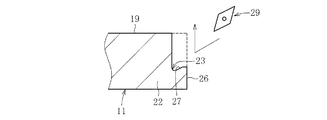
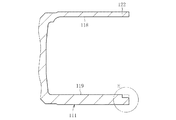
22 開口端部
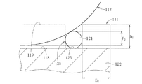
23,43,53 環状溝
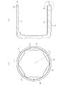
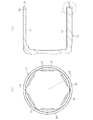
24 止め輪(サークリップ)
25,45,55 抜け止め機構
27 円錐面
29 旋削チップ
50 円筒面
Claims (7)
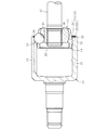
- 内周面にトラック溝が設けられたカップ状の外側継手部材と、前記外側継手部材との間で、前記トラック溝に配された転動体を介して角度変位を許容しながらトルクを伝達する内側継手部材とを備え、前記転動体および内側継手部材を含む内部部品が外側継手部材に軸方向摺動自在に収容された摺動式等速自在継手であって、
前記外側継手部材の開口端部の内周面に環状溝を形成し、前記環状溝に嵌着された止め輪に前記転動体を干渉させることにより、前記内部部品の軸方向変位量を規制する抜け止め機構を具備し、前記抜け止め機構の環状溝は、転動体と止め輪との接触点での軸方向接線との間で、外側継手部材の開口端部から奥側に向けて拡開する楔角度を持つように軸方向に対して傾斜した円錐面が形成され、
前記環状溝に嵌着された状態で最も拡径させた前記止め輪が前記トラック溝の底面よりも内径側に突出していることを特徴とする摺動式等速自在継手。 - 前記抜け止め機構の環状溝は、前記円錐面から外側継手部材の奥側に向けて延び、かつ、前記止め輪と接する円筒面が形成されている請求項1に記載の摺動式等速自在継手。
- 前記抜け止め機構は、前記止め輪と前記円筒面との接触点から前記環状溝の奥側端面までの軸方向寸法が、止め輪を構成する線材の半径よりも長くなるように設定されている請求項2に記載の摺動式等速自在継手。
- 前記抜け止め機構は、環状溝の軸方向入口内径が、環状溝に嵌着された状態での止め輪の内径よりも大きく、かつ、止め輪と環状溝との接触点での内径よりも小さくなるように設定されている請求項1〜3のいずれか一項に記載の摺動式等速自在継手。
- 前記抜け止め機構は、環状溝の軸方向入口内径が、外側継手部材の開口端部の全周に亘って環状溝に嵌着された状態での止め輪の内径よりも大きく設定されている請求項1〜4のいずれか一項に記載の摺動式等速自在継手。
- 内周面にトラック溝が設けられたカップ状の外側継手部材と、前記外側継手部材との間で、前記トラック溝に配された転動体を介して角度変位を許容しながらトルクを伝達する内側継手部材とを備え、前記転動体および内側継手部材を含む内部部品が外側継手部材に軸方向摺動自在に収容された摺動式等速自在継手の製造方法であって、
前記外側継手部材の開口端部の内周面に、前記転動体を干渉させるための止め輪が嵌着される環状溝を形成し、前記環状溝に嵌着された状態で最も拡径させた前記止め輪が前記トラック溝の底面よりも内径側に突出し、前記環状溝は、転動体と止め輪との接触点での軸方向接線との間で、外側継手部材の開口端部から奥側に向けて拡開する楔角度を持つように軸方向に対して傾斜した円錐面が旋削チップによる加工のみで形成されていることを特徴とする摺動式等速自在継手の製造方法。 - 前記環状溝は、前記円錐面から外側継手部材の奥側に向けて延び、かつ、前記止め輪と接する円筒面が、旋削チップによる加工のみで形成されている請求項6に記載の摺動式等速自在継手の製造方法。
Priority Applications (3)
| Application Number | Priority Date | Filing Date | Title |
|---|---|---|---|
| CN201780028583.0A CN109154329A (zh) | 2016-05-11 | 2017-04-19 | 滑动式等速万向联轴器及其制造方法 |
| PCT/JP2017/015743 WO2017195552A1 (ja) | 2016-05-11 | 2017-04-19 | 摺動式等速自在継手及びその製造方法 |
| US16/099,514 US11073179B2 (en) | 2016-05-11 | 2017-04-19 | Sliding-type constant velocity universal joint and method for manufacturing same |
Applications Claiming Priority (2)
| Application Number | Priority Date | Filing Date | Title |
|---|---|---|---|
| JP2016095303 | 2016-05-11 | ||
| JP2016095303 | 2016-05-11 |
Publications (2)
| Publication Number | Publication Date |
|---|---|
| JP2017207198A JP2017207198A (ja) | 2017-11-24 |
| JP6899663B2 true JP6899663B2 (ja) | 2021-07-07 |
Family
ID=60417012
Family Applications (1)
| Application Number | Title | Priority Date | Filing Date |
|---|---|---|---|
| JP2017025888A Expired - Fee Related JP6899663B2 (ja) | 2016-05-11 | 2017-02-15 | 摺動式等速自在継手及びその製造方法 |
Country Status (1)
| Country | Link |
|---|---|
| JP (1) | JP6899663B2 (ja) |
Families Citing this family (1)
| Publication number | Priority date | Publication date | Assignee | Title |
|---|---|---|---|---|
| JP2023161283A (ja) * | 2022-04-25 | 2023-11-07 | Ntn株式会社 | 摺動式等速自在継手 |
Family Cites Families (3)
| Publication number | Priority date | Publication date | Assignee | Title |
|---|---|---|---|---|
| JP3736133B2 (ja) * | 1998-08-28 | 2006-01-18 | 豊田工機株式会社 | 抜け止め装置及び等速ジョイント |
| JP2009180315A (ja) * | 2008-01-31 | 2009-08-13 | Ntn Corp | 動力伝達軸及びシャフトアッセンブリ |
| JP2011163410A (ja) * | 2010-02-08 | 2011-08-25 | Jtekt Corp | 摺動式トリポード型等速ジョイント |
-
2017
- 2017-02-15 JP JP2017025888A patent/JP6899663B2/ja not_active Expired - Fee Related
Also Published As
| Publication number | Publication date |
|---|---|
| JP2017207198A (ja) | 2017-11-24 |
Similar Documents
| Publication | Publication Date | Title |
|---|---|---|
| CN102209857B (zh) | 固定式等速万向接头及其制造方法、以及使用了该固定式等速万向接头的驱动车轮用轴承单元 | |
| US8262489B2 (en) | Constant velocity joint attachment method | |
| US20170298993A1 (en) | Propeller shaft | |
| WO2017073267A1 (ja) | 固定式等速自在継手 | |
| JP6879775B2 (ja) | 等速自在継手 | |
| CN108026977B (zh) | 固定式等速万向联轴器及车轮用轴承装置 | |
| JP6899663B2 (ja) | 摺動式等速自在継手及びその製造方法 | |
| CN109072985B (zh) | 用于传动轴的交叉槽等速万向节 | |
| JP2007078125A (ja) | 複合型等速自在継手 | |
| WO2011078103A1 (ja) | トリポード型等速自在継手 | |
| JP2010127311A (ja) | 固定式等速自在継手およびこれを用いた車輪軸受装置 | |
| JP2017203538A (ja) | 摺動式等速自在継手 | |
| JP2012189190A (ja) | 摺動式等速自在継手 | |
| WO2017195552A1 (ja) | 摺動式等速自在継手及びその製造方法 | |
| JP6901241B2 (ja) | 等速自在継手 | |
| WO2020066997A1 (ja) | 固定式等速自在継手 | |
| WO2019059291A1 (ja) | 等速自在継手 | |
| US11073179B2 (en) | Sliding-type constant velocity universal joint and method for manufacturing same | |
| JP5372364B2 (ja) | トリポード型等速自在継手 | |
| JP2010025207A (ja) | 等速自在継手 | |
| JP2024093536A (ja) | 動力伝達シャフト | |
| JP2023161283A (ja) | 摺動式等速自在継手 | |
| JP2020067142A (ja) | 固定式等速自在継手 | |
| JP4574999B2 (ja) | 回転駆動力伝達機構の選択方法 | |
| JP2026019580A (ja) | トルク伝達装置及び等速自在継手 |
Legal Events
| Date | Code | Title | Description |
|---|---|---|---|
| A621 | Written request for application examination |
Free format text: JAPANESE INTERMEDIATE CODE: A621 Effective date: 20200128 |
|
| A131 | Notification of reasons for refusal |
Free format text: JAPANESE INTERMEDIATE CODE: A131 Effective date: 20200818 |
|
| A521 | Request for written amendment filed |
Free format text: JAPANESE INTERMEDIATE CODE: A523 Effective date: 20201019 |
|
| A131 | Notification of reasons for refusal |
Free format text: JAPANESE INTERMEDIATE CODE: A131 Effective date: 20210129 |
|
| A521 | Request for written amendment filed |
Free format text: JAPANESE INTERMEDIATE CODE: A523 Effective date: 20210224 |
|
| TRDD | Decision of grant or rejection written | ||
| A01 | Written decision to grant a patent or to grant a registration (utility model) |
Free format text: JAPANESE INTERMEDIATE CODE: A01 Effective date: 20210528 |
|
| A61 | First payment of annual fees (during grant procedure) |
Free format text: JAPANESE INTERMEDIATE CODE: A61 Effective date: 20210615 |
|
| R150 | Certificate of patent or registration of utility model |
Ref document number: 6899663 Country of ref document: JP Free format text: JAPANESE INTERMEDIATE CODE: R150 |
|
| LAPS | Cancellation because of no payment of annual fees |