WO2017081965A1 - Dispositif d'évacuation d'air - Google Patents
Dispositif d'évacuation d'air Download PDFInfo
- Publication number
- WO2017081965A1 WO2017081965A1 PCT/JP2016/079790 JP2016079790W WO2017081965A1 WO 2017081965 A1 WO2017081965 A1 WO 2017081965A1 JP 2016079790 W JP2016079790 W JP 2016079790W WO 2017081965 A1 WO2017081965 A1 WO 2017081965A1
- Authority
- WO
- WIPO (PCT)
- Prior art keywords
- airflow
- air
- air flow
- vehicle
- wall
- Prior art date
- Legal status (The legal status is an assumption and is not a legal conclusion. Google has not performed a legal analysis and makes no representation as to the accuracy of the status listed.)
- Ceased
Links
Images









Classifications
-
- B—PERFORMING OPERATIONS; TRANSPORTING
- B60—VEHICLES IN GENERAL
- B60H—ARRANGEMENTS OF HEATING, COOLING, VENTILATING OR OTHER AIR-TREATING DEVICES SPECIALLY ADAPTED FOR PASSENGER OR GOODS SPACES OF VEHICLES
- B60H1/00—Heating, cooling or ventilating devices
- B60H1/34—Nozzles; Air-diffusers
- B60H1/3414—Nozzles; Air-diffusers with means for adjusting the air stream direction
Definitions
- the present disclosure relates to an air blowing device that blows out air.
- Patent Literature 1 discloses an air blowing device that blows air from a blowout port while bending the air along a guide wall using the Coanda effect. Specifically, this air blowing device An air outlet that blows air into the target space, a flow path forming member that internally forms an air flow path that is connected to the upstream side of the air flow of the air outlet, and an airflow deflecting member that generates two airflows having different flow velocities in the air flow path With.
- the flow path forming member has a first wall and a second wall facing the first wall.
- the air flow path has a first flow path between the air flow deflecting member and the first wall, and a second flow path between the air flow deflecting member and the second wall.
- the airflow deflecting member makes the width of the first flow path smaller than the width of the second flow path. Thereby, the 1st airflow which passed the 1st flow path is made faster than the 2nd airflow which passed the 2nd flow path.
- a part of the first wall on the air outlet side constitutes a guide wall that guides the first airflow.
- the guide wall extends toward the air outlet while bending from the second wall toward the first wall.
- the first airflow flows along the guide wall due to the Coanda effect. For this reason, the 1st air current is bent. Furthermore, the second air current is drawn into the high-speed first air current. For this reason, the second air stream is bent. For this reason, according to this air blowing apparatus, the air which flows through an air flow path can be bent in the direction which goes to a 1st wall from a 2nd wall, and can be blown out from a blower outlet.
- the above-described conventional air blowing device has the following problems. That is, when an air outlet is installed on the upper surface of the instrument panel, the airflow from the air outlet sticks to the vehicle front window even if air is blown from the air outlet toward the rear of the vehicle. This problem becomes more prominent as the position of the air outlet is closer to the front of the vehicle.
- the present disclosure aims to provide an air blowing device capable of suppressing the airflow from the air outlet from sticking to the vehicle front window when air is blown out from the air outlet toward the rear of the vehicle.
- the air blowing device is An air outlet that is provided on the upper surface of the instrument panel of the vehicle and blows out air;
- a flow path forming member that forms an air flow path connected to the air flow upstream side of the air outlet;
- An airflow deflecting member disposed in the air flow path and generating two airflows having different flow velocities in the air flow path;
- the flow path forming member has a front wall on the front side of the vehicle, a rear wall located on the vehicle rear side of the front wall and facing the front wall,
- the air flow path has a first flow path between the air flow deflecting member and the rear wall, and a second flow path between the air flow deflecting member and the front wall,
- the airflow deflecting member reduces the width of the first flow path in the vehicle front-rear direction to be smaller than the width of the second flow path in the vehicle front-rear direction, thereby causing the first airflow that has passed through the first flow path to It is faster than the second airflow that has passed through the road
- the first airflow flows along the guide wall by the Coanda effect.
- a 1st airflow can be bent to the vehicle rear side.
- the second airflow is attracted to the high-speed first airflow by the ejector effect.
- a 2nd airflow can be bent to the vehicle rear side.
- the second airflow flows along the front surface of the airflow deflecting member due to the Coanda effect.
- a 2nd airflow can be bent by the vehicle rear side.
- the airflow flowing through the air flow path can be greatly bent toward the vehicle rear side. Therefore, when air is blown out from the outlet toward the rear of the vehicle, it is possible to suppress the airflow from sticking to the vehicle front window.
- FIG. 1 It is sectional drawing which shows the vehicle mounting state of the air blowing apparatus in 1st Embodiment. It is a top view which shows arrangement
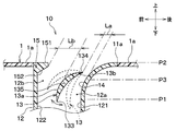
- the air blowing device 10 includes a blowout port 11, a duct 12, and an airflow deflecting member 13.
- the air outlet 11 blows air into the vehicle interior space.
- the air outlet 11 is provided on the upper surface portion 1 a of the instrument panel 1. More specifically, the blower outlet 11 is located in the windshield 2 side among the upper surface parts 1a. In other words, the blower outlet 11 is located in the range which overlaps with the windshield 2 among the upper surface parts 1a, when the windshield 2 is projected in parallel with the up-down direction with respect to the upper surface part 1a.
- the instrument panel 1 has an upper surface portion 1a and a front portion (not shown).
- the instrument panel 1 is an instrument panel provided in front of the passenger compartment.
- the instrument panel 1 refers to the entire panel located in front of the front seat in the passenger compartment, including not only the part where the instruments are arranged, but also the part that houses the audio and the air conditioner.
- the air outlets 11 are arranged at two locations on the front of the driver seat 4 a and the front of the passenger seat 4 b of the right-hand drive vehicle.
- the blower outlet 11 of the front of the driver's seat 4a is demonstrated, the blower outlet 11 arrange
- the air outlet 11 is elongated in the left-right direction.
- the longitudinal direction of the opening shape of the blower outlet 11 is along the left-right direction.
- the length of the air outlet 11 in the left-right direction is longer than the length of the seat 4 in the left-right direction.
- the length of the left-right direction of the blower outlet 11 may be equal to or shorter than the length of the seat 4 in the left-right direction.
- the blower outlet 11 has opening edges 11a, 11b, 11c, and 11d.
- the opening edge portions 11a to 11d include a pair of long sides 11a and 11b and a pair of short sides 11c and 11d.
- the air outlet 11 is switched to at least one of the defroster mode and the face mode by the airflow deflecting member 13 shown in FIG. 1 and blows out the temperature-adjusted air into the vehicle interior space.
- the defroster mode is a blowing mode in which air is blown toward the windshield 2. This clears the windows from cloudiness.
- the face mode is a blowing mode in which air is blown out toward the upper body of the front seat occupant 5.
- the air outlet 11 is constituted by an opening formed at the end of the duct 12.
- the duct 12 is connected to the air outlet 11.
- the duct 12 connects the air outlet 11 and the air conditioning unit 20.
- the air conditioning unit 20 is disposed inside the instrument panel 1. The air conditioning unit 20 adjusts the temperature of the blown air toward the vehicle interior.
- the duct 12 is a flow path forming member that forms an air flow path connected to the air flow upstream side of the air outlet 11 inside.
- the duct 12 forms an air flow path through which air blown from the air conditioning unit 20 flows.
- the duct 12 is made of resin and is configured separately from the air conditioning unit 20.
- the duct 12 may be formed integrally with the air conditioning unit 20.
- the duct 12 has a rear wall 121 located on the rear side and a front wall 122 located on the front side.
- the rear wall 121 and the front wall 122 are opposed to each other in the front-rear direction.
- the air flow path inside the duct 12 has a first flow path 12a and a second flow path 12b.
- the first flow path 12 a is formed between the airflow deflecting member 13 and the rear wall 121.
- the second flow path 12 b is formed between the airflow deflecting member 13 and the front wall 122.
- the airflow deflecting member 13 is disposed in the air flow path inside the duct 12.
- the airflow deflecting member 13 generates two airflows having different flow velocities in the duct 12.
- the airflow deflecting member 13 varies the velocity of the airflow that has passed through the first flow path 12a and the airflow that has passed through the second flow path 12b.
- the airflow deflecting member 13 has a rear surface 131 that is a rear surface and a front surface 132 that is a front surface.
- the rear surface 131 extends from the bottom to the top while bending backward.
- the rear surface 131 includes a curved surface having a predetermined radius of curvature R1.
- the front surface 132 extends from the bottom to the top while bending backward.
- the front surface 132 includes a curved surface having a predetermined radius of curvature R2.
- a cantilever door is adopted as the airflow deflecting member 13.
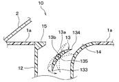
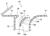
- the airflow deflecting member 13 includes a door main body 13a and a rotation shaft 13b provided on the door main body 13a.
- the rotating shaft 13b is arranged in parallel in the left-right direction. For this reason, the airflow deflecting member 13 rotates in the front-rear direction around the rotation shaft 13b.
- the door main body 13a is a plate-shaped part.
- the door body 13 a has a rear surface 131 and a front surface 132.
- the front surface 132 has a curved surface shape that extends from the bottom to the top while bending backward, over the entire area from the air flow downstream end 134 of the door main body 13a to the air flow upstream end 133 of the door main body 13a. Yes.
- the rotary shaft 13b is located at the end of the door body 13a on the downstream side of the air flow. That is, the rotary shaft 13b is located at a position closer to the downstream end 134 than the center position 135 that is equidistant from both the air flow upstream end 133 and the air flow downstream end 134 of the door body 13a. For this reason, as for the rotating shaft 13b, the distance from the air flow downstream end 134 of the door main-body part 13a to the rotating shaft 13b becomes shorter than the distance from the air-flow upstream end 133 of the door main-body part 13a to the rotating shaft 13b. ing.
- the position of the rotating shaft 13b is not limited to the position shown in FIG.
- the position of the rotating shaft 13b may be a position between the center position 135 and the downstream end 134 in the door main body 13a. That is, the position of the rotary shaft 13b is set such that the position of the rotary shaft 13b from the downstream end 134 of the door body 13a to the rotary shaft 13b is greater than the distance from the upstream end 133 of the door main body 13a to the rotary shaft 13b. Any position may be used as long as the distance to is shorter.
- the distance from the air flow downstream end 134 of the door main body 13a to the rotary shaft 13b is zero.
- the airflow deflecting member 13 is arranged on the outlet 11 side of the duct 12. That is, the downstream end 134 of the airflow deflecting member 13 is positioned above the intermediate position P3 in the vertical direction between the position P1 at which bending starts to the rear side and the position P2 at the bending end of the guide wall 14 described later. .
- the bending end position P ⁇ b> 2 is the position of the opening edge 11 a of the air outlet 11.
- the airflow deflecting member 13 is disposed at a position where the width of the first flow path 12a in the front-rear direction is smaller than the width of the second flow path 12b in the front-rear direction. Specifically, the distance in the front-rear direction between the downstream end 134 of the airflow deflection member 13 and the rear wall 121 is greater than the distance in the front-rear direction between the downstream end 134 of the airflow deflection member 13 and the front wall 122.
- the airflow deflecting member 13 is arranged at a position where the airflow is reduced.
- a part of the rear wall 121 on the outlet 11 side has a guide wall 14 for guiding a first air flow F1 described later.
- the guide wall 14 is continuous with the upper surface portion 1 a of the instrument panel 1.
- the guide wall 14 guides the first air flow F1 by bending the first air flow F1 along the wall surface by the Coanda effect.
- the wall surface of the guide wall 14 extends from the bottom to the top while bending backward. In other words, the wall of the guide wall 14 is bent so that the distance between the front wall 122 and the rear wall 121 widens toward the downstream side of the air flow.
- the wall surface of the guide wall 14 is curved so as to be convex toward the front of the vehicle.
- the wall surface of the guide wall 14 has a curved surface shape having a predetermined radius of curvature R3.
- the curvature radius R3 of the guide wall 14 is larger than the curvature radius R2 of the front surface 132 of the airflow deflecting member 13.
- the duct 12 has a protruding portion 15 that protrudes rearward from the front wall 122.
- the protrusion 15 is provided in a portion of the front wall 122 on the downstream side of the air flow with respect to the air flow upstream end 133 of the airflow deflecting member 13.
- the protrusion 15 is provided at the end of the front wall 122 on the downstream side of the air flow.
- the upper surface 151 of the protrusion 15 is continuous with the surface of the upper surface 1 a of the instrument panel 1.
- the lower surface 152 of the protruding portion 15 is a flat surface that extends straight obliquely backward from the bottom to the top.
- the protrusion 15 is not limited to being formed as a part of the front wall 122.
- the protrusion 15 may be formed as a separate body from the front wall 122.
- the blowing direction of air from the blowout port 11 is switched by the rotation of the airflow deflecting member 13.
- the position of the airflow deflecting member 13 is the position shown in FIG. That is, the position of the upstream end 133 of the airflow deflecting member 13 is an intermediate position between the rear wall 121 and the front wall 122.
- the air flowing inside the duct 12 is divided into a first air flow F1 passing through the first flow path 12a and a second air flow F2 passing through the second flow path 12b.
- the first airflow F1 that has passed through the first flow path 12a flows along the guide wall 14 due to the Coanda effect. For this reason, the first airflow F1 is bent backward.
- the air flow deflecting member 13 causes the flow passage width of the first flow passage 12a to be narrower than the flow passage width of the second flow passage 12b. For this reason, the first airflow F1 that has passed through the first flow path 12a is faster than the second airflow F2 that has passed through the second flow path 12b.
- the high-speed first air flow F ⁇ b> 1 flows, a negative pressure is generated on the downstream side of the air flow deflecting member 13.
- the second air flow F2 is drawn to the downstream side of the air flow deflecting member 13 and merges with the first air flow F1. That is, the second air flow F2 is pulled by the first air flow F1 due to the ejector effect. Further, the second air flow F2 flows along the front surface 132 of the air flow deflecting member 13 due to the Coanda effect. Accordingly, the second air flow F2 is also bent backward.
- the air flowing inside the duct 12 is blown out from the air outlet 11 toward the upper body of the front seat occupant.
- the speed difference between the first airflow F1 and the second airflow F2 can be adjusted by the passenger manually adjusting the position of the airflow deflecting member 13 or the control device automatically adjusting the position.
- the speed difference By adjusting the speed difference, the direction of the air blown out from the air outlet 11 can be finely adjusted.
- the airflow deflecting member 13 has the rotation shaft 13b in a portion closer to the downstream end 134 than the center position 135. Therefore, as shown in FIG. 4, the rotation of the airflow deflecting member 13 maintains the state where the distance La between the upstream end 133 of the airflow deflecting member 13 and the guide wall 14 is almost constant, and the front of the airflow deflecting member 13 and the front.
- the distance Lb from the wall 122 can be changed.
- the speed of the airflow is determined by the width of the flow path.
- the speed of the second airflow F2 that has passed through the second flow path 12b can be changed while the speed of the first airflow F1 that has passed through the first flow path 12a is brought close to a constant speed by the rotation of the airflow deflecting member 13. it can.
- the speed difference between the first airflow F1 and the second airflow F2 is adjusted according to the present embodiment as compared to the case where both the distance La and the distance Lb change. It becomes easy.
- the position of the rotating shaft 13b is preferably closer to the downstream end 134, and the position of the downstream end 134 is most preferable.
- the position of the airflow deflecting member 13 is the position shown in FIG. That is, the position of the upstream end 133 of the airflow deflecting member 13 is a position closer to the rear wall 121 than the position in the face mode.
- the flow rate of the first air flow F1 is smaller and the flow rate of the second air flow F2 is larger than in the face mode. For this reason, the force by which the second air flow F2 is pulled by the first air flow F1 is weak due to the ejector effect.
- the front surface 132 of the airflow deflecting member 13 is in a state of extending upward from the rear side as compared with the case of the face mode. For this reason, the air flow direction along the front surface 132 is closer to the upper side than in the face mode.
- the air flowing inside the duct 12 is blown upward from the air outlet 11.
- air whose temperature has been adjusted by the air conditioning unit 20, for example, warm air is blown out from the air outlet 11 toward the windshield 2.
- the air blowing device 10 of the present embodiment includes the air outlet 11, the duct 12, and the airflow deflecting member 13.
- the duct 12 has a rear wall 121 and a front wall 122. A part of the rear wall 121 on the outlet 11 side constitutes the guide wall 14.
- the guide wall 14 has a curved surface shape that extends from the bottom to the top while continuously bending to the rear side.
- the airflow deflecting member 13 makes the width of the first flow path 12a in the front-rear direction smaller than the width of the second flow path 12b in the vehicle rear direction. Thereby, the 1st airflow F1 which passed the 1st flow path 12a is made faster than the 2nd airflow F2 which passed the 2nd flow path 12b.
- the first air flow F1 flows along the guide wall 14 due to the Coanda effect. Thereby, the 1st air current F1 bends to the back side. Due to the ejector effect, the high-speed first air flow F1 pulls the low-speed second air flow F2. Thereby, the 2nd air current F2 bends to the back side.
- the front surface 132 of the airflow deflecting member 13 has a curved shape that is continuously bent. In the face mode, the airflow deflecting member 13 is in a state of extending from the bottom to the top while the front surface 132 is bent backward.
- the second airflow F2 flows along the front surface 132 of the airflow deflecting member 13 due to the Coanda effect. Thereby, the 2nd airflow F2 can be bent by the back side.
- the airflow flowing inside the duct 12 can be greatly bent backward. Therefore, it can suppress that an air current sticks to a vehicle front window.
- the downstream end 134 of the airflow deflecting member 13 is located above the intermediate position P3 of the guide wall 14. Rather than bending the airflow by the Coanda effect on the side away from the air outlet 11, the airflow from the air outlet 11 tends to be directed backward when the airflow is bent by the Coanda effect on the side closer to the air outlet 11. Therefore, according to the present embodiment, the airflow flowing in the duct 12 in the face mode compared to the case where the downstream end 134 of the airflow deflecting member 13 is located below the intermediate position P3 of the guide wall 14. Can be bent more greatly on the rear side.
- the air blowing device 10 of the present embodiment includes a protruding portion 15.
- the protrusion 15 can bend the portion of the second air flow F2 near the front wall 122 to the rear side. Thereby, at the time of face mode, the airflow which flows through the inside of the duct 12 can be bent largely to the back side.
- the curvature radius R3 of the guide wall 14 is larger than the curvature radius R2 of the front surface 132 of the airflow deflecting member 13. That is, the guide wall 14 is curved more gently than the front surface 132 of the airflow deflecting member 13. According to this, compared with the case where the curvature radius R3 of the guide wall 14 is made smaller than the curvature radius R2 of the front surface 132 of the airflow deflecting member 13, the first airflow that flows along the guide wall 14 due to the Coanda effect. It can suppress that F1 peels from the guide wall 14.
- the air blowing device 10 of the present embodiment is obtained by adding one guide member 16 to the air blowing device 10 of the first embodiment.
- the other structure of the air blowing apparatus 10 of this embodiment is the same as the air blowing apparatus 10 of 1st Embodiment.
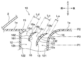
- the guide member 16 is disposed between the airflow deflecting member 13 and the front wall 122.
- the downstream end 164 of the guide member 16 is located above the intermediate position P3 of the guide wall 14 as with the airflow deflecting member 13.
- the airflow deflecting member 13 is disposed at a position where the width of the first flow path 12a in the front-rear direction is smaller than the width of the second flow path 12b in the front-rear direction.
- the guide member 16 has the same shape as the airflow deflecting member 13. That is, the guide member 16 has a rear surface 161 that is a rear surface and a front surface 162 that is a front surface.
- the rear surface 161 extends from the bottom to the top while bending backward. More specifically, the rear surface 161 includes a curved surface that extends from the bottom to the top while continuously bending to the rear side.
- the front surface 162 extends from the bottom to the top while bending backward. More specifically, the front surface 162 includes a curved surface extending from the bottom to the top while continuously bending to the rear side.
- the length of the guide member 16 is shorter than the length of the airflow deflecting member 13.
- the guide member 16 is a cantilever door similar to the airflow deflecting member 13. That is, the guide member 16 includes a door main body portion 16a and a rotation shaft 16b provided on the door main body portion 16a.
- the door body portion 16a is a plate-shaped portion.
- the door main body portion 16 a has a rear surface 161 and a front surface 162.
- the front surface 162 has a curved surface shape that extends from the bottom to the top while bending to the rear side over the entire region from the air flow downstream end 164 of the door body portion 16a to the air flow upstream end 163 of the door body portion 16a. Yes.
- the rotary shaft 16b is located at the end of the door body 16a on the downstream side of the air flow. That is, the rotary shaft 16b is located at a position closer to the downstream end 164 than the center position 165 that is equidistant from both the air flow upstream end 163 and the air flow downstream end 164 of the door body 16a. For this reason, the distance from the air flow upstream end 163 of the door main body portion 16a to the rotation shaft 16b is shorter in the rotation shaft 16b than the distance from the air flow downstream end 164 of the door main body portion 16a to the rotation shaft 16b. ing.
- the rotating shaft 16b is arranged in parallel in the left-right direction. For this reason, the guide member 16 rotates in the front-rear direction around the rotation shaft 16b.
- the guide member 16 is configured to rotate in conjunction with the airflow deflecting member 13.
- the position of the rotating shaft 16b is not limited to the position shown in FIG.
- the position of the rotary shaft 16b is more than the distance from the air flow upstream end 163 of the door main body portion 16a to the rotary shaft 16b of the door main body portion 16a than the distance from the air flow downstream end 164 of the door main body portion 16a to the rotary shaft 16b. Any position where the distance is shorter may be used.
- the guide member 16 is disposed so as to decrease in order of the interval Ld, the interval Lc, and the interval La.
- the interval La is the shortest distance between the airflow deflecting member 13 and the guide wall 14.
- the distance between the airflow deflecting member 13 and the guide wall 14 at the position of the downstream end 134 of the airflow deflecting member 13 is the shortest distance.
- the interval Lc is the shortest distance between the guide member 16 and the airflow deflecting member 13.
- the distance between the guide member 16 and the airflow deflecting member 13 at the position of the downstream end 164 of the guide member 16 is the shortest distance.
- the distance Ld is the shortest distance between the front wall 122 and the guide member 16.
- the interval La, the interval Lc, and the interval Ld are the first interval, the second interval, and the third interval, respectively.
- the airflow deflecting member 13 and the guide member 16 are at the positions shown in FIGS.
- the airflow deflecting member 13 forms a first airflow F1 and a second airflow F2.
- the guide member 16 divides the second airflow F2 into a third airflow F3 that flows on the rear surface 161 side of the guide member 16 and a fourth airflow F4 that flows on the front surface 162 side of the guide member 16.
- the effect of the first embodiment can be obtained. That is, the first air flow F ⁇ b> 1 flows along the guide wall 14 due to the Coanda effect. Due to the airflow deflecting member 13, the first airflow F1 becomes faster than the third airflow F3 and the fourth airflow F4. That is, the first airflow F1 becomes faster than the second airflow F2 by the airflow deflecting member 13. Due to the ejector effect, the third air stream F3 and the fourth air stream F4 are pulled by the high-speed first air stream F1. Due to the Coanda effect, the third airflow F3 flows along the front surface 132 of the airflow deflecting member 13.
- the following effects can be obtained. That is, the third air flow F3 becomes faster than the fourth air flow F4 by the guide member 16. For this reason, the fourth air flow F4 is pulled by the high-speed third air flow F3 by the ejector effect. The fourth airflow F4 flows along the front surface 162 of the guide member 16 due to the Coanda effect. Thereby, compared with the case where the guide member 16 is not arrange
- the air blowing device 10 of the present embodiment even if the airflow flowing inside the duct 12 is a large flow rate, the airflow flowing inside the duct 12 can be largely bent backward.
- the air blowing device 10 of this embodiment is fixed so that the guide member 16 does not move relative to the air flow path.
- the guide member 16 of this embodiment is different from the guide member 16 of the second embodiment only in that it does not have the rotation shaft 16b.
- the other structure of the air blowing apparatus of this embodiment is the same as the air blowing apparatus 10 of 2nd Embodiment.
- the guide member 16 may be fixed. This also provides the same effect as in the second embodiment.
- the air blowing device 10 of the present embodiment is fixed so that the guide member 16 does not move relative to the air flow path.
- the guide member 16 of this embodiment is different from the guide member 16 of the second embodiment only in that it does not have the rotation shaft 16b.
- the airflow deflecting member 13 is fixed so as not to move with respect to the air flow path.
- the airflow deflecting member 13 is different from the airflow deflecting member 13 of the first embodiment only in that the rotating shaft 13b is not provided.
- the other structure of the air blowing device 10 of this embodiment is the same as the air blowing device 10 of 2nd Embodiment.
- the air blowing device 10 of this embodiment performs only the blowing mode in the face mode.
- both the guide member 16 and the airflow deflecting member 13 may be fixed. This also provides the same effect as in the second embodiment.
- the guide member 16 is arranged so that the interval Ld and the interval Lc are the same, and the interval La is smaller than both the interval Ld and the interval Lc. ing.
- the other structure of the air blowing apparatus of this embodiment is the same as the air blowing apparatus 10 of 2nd Embodiment.
- the guide member 16 causes the second air flow F2 to flow on the rear surface 161 side of the guide member 16 and on the front surface 162 side of the guide member 16. It is divided into four air currents F4.
- the fourth air flow F4 flows along the front surface 162 of the guide member 16 due to the Coanda effect. Thereby, compared with the case where the guide member 16 is not arrange
- the air blowing device 10 of the present embodiment even if the airflow flowing inside the duct 12 is a large flow rate, the airflow flowing inside the duct 12 can be largely bent backward.
- the air blowing device 10 of this embodiment is obtained by adding two guide members 16 and 17 to the air blowing device 10 of the first embodiment.
- the other structure of the air blowing apparatus 10 of this embodiment is the same as the air blowing apparatus 10 of 1st Embodiment.
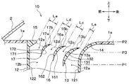
- the two guide members 16 and 17 are arranged between the airflow deflecting member 13 and the front wall 122 side by side in the front-rear direction with a space between each other.
- the downstream ends 164 and 174 of the guide members 16 and 17 are located above the intermediate position P3 of the guide wall 14 in the same manner as the airflow deflecting member 13.
- the airflow deflecting member 13 is disposed at a position where the width of the first flow path 12a in the front-rear direction is smaller than the width of the second flow path 12b in the front-rear direction.
- each of the two guide members 16 and 17 has the same shape as the airflow deflecting member 13. That is, each of the guide members 16 and 17 has rear surfaces 161 and 171 that are rear surfaces and front surfaces 162 and 172 that are front surfaces.
- the rear surfaces 161 and 171 extend from the bottom to the top while bending rearward. More specifically, the rear surfaces 161 and 171 include curved surfaces that extend from the bottom to the top while continuously bending to the rear side.
- the front surfaces 162 and 172 extend from the bottom to the top while bending backward. More specifically, the front surfaces 162 and 172 include curved surfaces that extend from the bottom to the top while continuously bending to the rear side.
- the lengths of the guide members 16 and 17 are shorter than the length of the airflow deflecting member 13. The length of the guide member 17 is shorter than the length of the guide member 16.
- the guide members 16 and 17 are cantilever doors similar to the airflow deflecting member 13. That is, the guide members 16 and 17 include door main body portions 16a and 17a and rotary shafts 16b and 17b provided on the door main body portions 16a and 17a.
- the door body portions 16a and 17a are plate-shaped portions.
- the door main body portions 16 a and 17 a have rear surfaces 161 and 171 and front surfaces 162 and 172.
- the front surfaces 162 and 172 are directed from the bottom to the top while bending rearward over the entire area from the air flow downstream ends 164 and 174 of the door main body portions 16a and 172 to the air flow upstream ends 163 and 173 of the door main body portions 16a and 17a. It has a curved shape extending.
- the rotary shafts 16b and 17b are located at the ends of the door main body portions 16a and 17a on the downstream side of the air flow. That is, the rotary shafts 16b and 17b are arranged at the downstream ends 164 from the center positions 165 and 175 that are equidistant from both the air flow upstream ends 163 and 173 and the air flow downstream ends 164 and 174 of the door main body portions 16a and 17a. 174. For this reason, the rotation shafts 16b and 17b have the air flow downstream ends 164 and 174 of the door main body portions 16a and 17a, rather than the distance from the air flow upstream ends 163 and 173 of the door main body portions 16a and 17a to the rotation shafts 16b and 17b. To the rotary shafts 16b and 17b is shorter.
- the rotary shafts 16b and 17b are arranged in parallel in the left-right direction. For this reason, the guide members 16 and 17 rotate in the front-rear direction around the rotation shafts 16b and 17b.
- the guide members 16 and 17 are configured to rotate in conjunction with the airflow deflecting member 13.
- the positions of the rotary shafts 16b and 17b are not limited to the positions shown in FIG.
- the positions of the rotary shafts 16b and 17b are the door main body portions 16a and 17a rather than the distance from the air flow upstream ends 163 and 173 of the door main body portions 16a and 17a to the rotary shafts 16b and 17b.
- the position may be any position.
- Each of the guide members 16 and 17 is arranged so as to decrease in order of the interval Le, the interval Ld, the interval Lc, and the interval La.
- the interval Le is the shortest distance between the front wall 122 and the guide member 17.
- the distance Ld is the shortest distance between the guide member 17 and the guide member 16.
- the interval Lc and the interval La are as described in the second embodiment.
- a plurality of flow paths 12e, 12d, 12c, and 12a are formed side by side in the front-rear direction between the front wall 122 and the rear wall 121 by the two guide members 16 and 17 and the airflow deflecting member 13.
- the shortest distances Le, Ld, Lc, and La between adjacent walls of the two guide members 16, 17, the airflow deflecting member 13, the front wall 122, and the rear wall 121 become smaller toward the rear side.
- the two guide members 16 and 17 are disposed (that is, Le> Ld> Lc> La).
- the airflow deflecting member 13 and the guide members 16 and 17 are at the positions shown in FIGS.
- the first air flow F ⁇ b> 1 and the second air flow F ⁇ b> 2 are formed by the air flow deflecting member 13.
- the guide member 16, 17 causes the second air flow F 2 to flow on the rear surface 161 side of the guide member 16, the fourth air flow F 4 flowing on the front surface 162 side of the guide member 16, and the front surface 172 side of the guide member 17. It is divided into the 5th air current F5 which flows through.
- the effect of the first embodiment can be obtained. That is, the first air flow F ⁇ b> 1 flows along the guide wall 14 due to the Coanda effect.
- the first airflow F1 becomes faster than the third airflow F3, the fourth airflow F4, and the fifth airflow F5 by the airflow deflecting member 13. That is, the first airflow F1 becomes faster than the second airflow F2 by the airflow deflecting member 13.
- Due to the ejector effect the third airflow F3, the fourth airflow F4, and the fifth airflow F5 are pulled by the high-speed first airflow F1. Due to the Coanda effect, the third airflow F3 flows along the front surface 132 of the airflow deflecting member 13.
- the third air flow F3 becomes faster than the fourth air flow F4 by the guide member 16.
- the fourth airflow F4 is pulled by the third airflow F3 due to the ejector effect.
- the fourth airflow F4 flows along the front surface 162 of the guide member 16 due to the Coanda effect.
- the fourth air flow F4 becomes faster than the fifth air flow F5 by the guide member 17.
- the fifth air flow F5 is pulled by the fourth air flow F4 due to the ejector effect.
- the fifth air flow F5 flows along the front surface 172 of the guide member 17 by the Coanda effect.
- the second air flow F2 flowing through the second flow path 12b can be largely bent backward. Therefore, according to the air blowing device 10 of the present embodiment, even if the airflow flowing inside the duct 12 is a large flow rate, the airflow flowing inside the duct 12 can be largely bent backward.
- the air blowing device 10 of the present embodiment is fixed so that the two guide members 16 and 17 do not move relative to the air flow path.
- the guide members 16 and 17 of this embodiment differ from the guide members 16 and 17 of the sixth embodiment only in that they do not have the rotation shafts 16b and 17b.
- Other configurations of the air blowing device of the present embodiment are the same as those of the air blowing device 10 of the sixth embodiment.
- the two guide members 16 and 17 may be fixed. This also provides the same effect as in the sixth embodiment.
- the air blowing device 10 of the present embodiment is fixed so that the two guide members 16 and 17 do not move relative to the air flow path.
- the guide members 16 and 17 of this embodiment differ from the guide members 16 and 17 of the sixth embodiment only in that they do not have the rotation shafts 16b and 17b.
- the airflow deflecting member 13 is fixed so as not to move with respect to the air flow path.
- the airflow deflecting member 13 is different from the airflow deflecting member 13 of the first embodiment only in that it does not have the rotation shaft 13b.
- the other structure of the air blowing apparatus 10 of this embodiment is the same as the air blowing apparatus 10 of 6th Embodiment.
- the air blowing device 10 of this embodiment performs only the blowing mode in the face mode.
- the air blowing device 10 of the present embodiment has the same interval Le, interval Ld, and interval Lc, so that the interval La is smaller than all of the interval Le, the interval Ld, and the interval Lc.
- Each of the two guide members 16 and 17 is disposed.
- the other structure of the air blowing apparatus 10 of this embodiment is the same as the air blowing apparatus 10 of 6th Embodiment.
- the guide members 16 and 17 cause the second air flow F2 to flow between the third air flow F3 flowing on the rear surface 161 side of the guide member 16 and the front surface 162 side of the guide member 16. It is divided into a fourth air flow F4 that flows and a fifth air flow F5 that flows on the front surface 172 side of the guide member 17.
- the fourth air flow F4 flows along the front surface 162 of the guide member 16 due to the Coanda effect.
- the fifth air flow F5 flows along the front surface 172 of the guide member 17 by the Coanda effect.
- the second air flow F2 flowing through the second flow path 12b can be largely bent backward as compared with the case where the two guide members 16 and 17 are not disposed.
- the air blowing device 10 of the present embodiment even if the airflow flowing inside the duct 12 is a large flow rate, the airflow flowing inside the duct 12 can be largely bent backward.
- the rear surface 131 of the airflow deflecting member 13 has a shape extending from the bottom to the top while bending backward, but is not limited thereto. As shown in FIG. 18, the rear surface 131 may be a flat surface that extends straight obliquely rearward from bottom to top. The same applies to the rear surfaces 161 and 171 of the guide members 16 and 17.
- the rotating shaft 13b of the airflow deflecting member 13 is located at the end of the door body 13a on the downstream side of the air flow, but is not limited thereto. As shown in FIG. 19, the rotating shaft 13b may be located at a central position 135 that is equidistant from both the upstream end 133 and the downstream end 134 of the door body 13a. Moreover, as shown in FIG. 20, you may be located in the edge part of the air flow upstream of the door main-body part 13a.
- the lower surface 152 of the projecting portion 15 is a flat surface that extends straight obliquely rearward from below to above, but is not limited thereto.
- the lower surface 152 may be a curved surface that extends while being bent obliquely backward from the bottom to the top.
- the lower surface 152 may be a flat surface extending horizontally from the front to the rear.
- each of the upper surface 151 and the lower surface 152 may be a flat surface extending obliquely downward from the front to the rear.
- the shape of the lower surface 152 is a shape that extends obliquely rearward from the bottom to the top, like the protruding portion 15 of the first embodiment and the protruding portion 15 shown in FIG. Thereby, the turbulence of the air flow generated on the upstream side of the air flow of the protrusion 15 can be suppressed.
- the protruding portion 15 is provided, but the protruding portion 15 may not be provided. Even in such a case, the effect of the shape of the front surface 132 of the airflow deflecting member 13 can be obtained.
- the front surface 132 of the airflow deflecting member 13 has a curved surface extending from the bottom to the top while continuously bending to the rear side, but is not limited thereto.
- the front surface 132 may have a shape that extends from the bottom to the top while bending to the rear side.
- the front surface 132 may have a shape in which a flat surface has a corner and is bent rearward. The same applies to the shapes of the guide walls 14 and the front surfaces 162 and 172 of the guide members 16 and 17.
- the air blowing device 10 includes the two guide members 16 and 17, but the present invention is not limited to this.
- the air blowing device 10 may include three or more guide members.
- an air blowing apparatus is provided with a blower outlet, a flow-path formation member, and an airflow deflection
- a blower outlet is provided in the upper surface part of the instrument panel of a vehicle.
- the flow path forming member forms an air flow path connected to the air flow upstream side of the air outlet.
- the flow path forming member has a front wall and a rear wall.
- the air flow path has a first flow path and a second flow path.
- the airflow deflecting member makes the first airflow that has passed through the first flow path faster than the second airflow that has passed through the second flow path.
- a part of the rear wall on the outlet side constitutes a guide wall for guiding the first airflow.
- the guide wall extends from the bottom to the top while bending toward the vehicle rear side.
- the airflow deflecting member has at least a plate-shaped portion.
- the plate-shaped portion has a front surface that is a front surface of the vehicle. The front surface of the plate-shaped portion extends from the bottom to the top while bending toward the vehicle rear side.
- the air flow downstream end of the airflow deflecting member is located above the intermediate position on the guide wall.
- the airflow becomes easier to go backwards. Therefore, according to this, compared with the case where the downstream end of the airflow deflecting member is located below the intermediate position of the guide wall, the airflow flowing inside the air flow path can be bent more greatly on the rear side. .
- the airflow deflecting member has a rotating shaft provided in the plate-shaped portion.
- the rotating shaft is provided at a position where the distance from the air flow downstream end of the plate-shaped portion to the rotating shaft is shorter than the distance from the air flow upstream end of the plate-shaped portion to the rotating shaft.
- the distance between the airflow deflecting member and the front wall can be changed while maintaining a state where the distance between the upstream end of the airflow deflecting member and the guide wall is almost constant.
- the speed of the airflow is determined by the width of the flow path. Therefore, the speed of the second airflow that has passed through the second flow path can be changed while the speed of the first airflow that has passed through the first flow path approaches a constant speed by the rotation of the airflow deflecting member. For this reason, when the airflow deflecting member rotates, it becomes easier to adjust the speed difference between the first airflow and the second airflow as compared with the case where both of the distances described above change.
- the air blowing device further includes a guide member disposed between the airflow deflecting member and the front wall.
- the guide member has at least a plate-shaped portion.
- the plate-shaped portion of the guide member has a front surface that is a front surface of the vehicle.
- the front surface of the plate-shaped portion of the guide member extends from bottom to top while bending toward the vehicle rear side.
- the second airflow is divided by the guide member into a third airflow flowing on the rear surface side of the guide member and a fourth airflow flowing on the front surface side of the guide member.
- a 4th airflow flows along the front surface of a guide member by the Coanda effect.
- the guide members are arranged so as to decrease in the order of the third interval, the second interval, and the first interval.
- the first interval is the shortest distance between the airflow deflecting member and the rear wall.
- the second interval is the shortest distance between the guide member and the airflow deflecting member.
- the third distance is the shortest distance between the guide member and the front wall.
- the third airflow is faster than the fourth airflow due to the guide member. For this reason, the fourth air stream is pulled by the high-speed third air stream by the ejector effect. Thereby, the 2nd airflow which flows through the 2nd channel can be bent greatly to the back side.
- the guide member is fixed so as not to move with respect to the air flow path.
- the guide member can thus be fixed.
- the guide member has a rotation shaft provided in the plate-shaped portion.
- the rotating shaft of the guide member is provided at a position where the distance from the downstream end of the plate-shaped portion to the rotating shaft is shorter than the distance from the upstream end of the plate-shaped portion to the rotating shaft.
- the guide member can thus be movable.
- the air blowing device further includes a plurality of guide members arranged between the airflow deflecting member and the front wall and arranged side by side in the vehicle front-rear direction.
- Each of the plurality of guide members has at least a plate-shaped portion.
- Each of the plate-shaped portions of the plurality of guide members has a front surface that is a front surface of the vehicle.
- Each of the front surfaces of the plate-shaped portions of the plurality of guide members extends from the bottom to the top while bending toward the vehicle rear side.
- the second airflow is divided into a plurality of airflows by the plurality of guide members. And in each of a plurality of guide members, the air current which flows through the front side of one guide member flows along the front of the guide member by the Coanda effect. Thereby, compared with the case where the some guide member is not arrange
- a plurality of flow paths are formed side by side in the vehicle front-rear direction between the front wall and the rear wall by the plurality of guide members and the airflow deflecting member.
- the plurality of guide members are arranged so that the minimum value of the channel widths of the plurality of channels becomes smaller toward the vehicle rear side.
- the flow path width of each of the plurality of flow paths is an interval between adjacent walls among the plurality of guide members, the airflow deflecting member, the front wall, and the rear wall.
- the airflow flowing on the rear surface side of one guide member is faster than the airflow flowing on the front surface side of the guide member. For this reason, the airflow flowing on the front side of one guide member is pulled by the airflow flowing on the rear side of the guide member due to the ejector effect. Thereby, the 2nd airflow which flows through the 2nd channel can be bent greatly to the back side.
- each of the plurality of guide members is fixed so as not to move with respect to the air flow path.
- a plurality of guide members can be fixed in this way.
- each of the plurality of guide members has a rotation shaft provided on the plate-shaped portion.
- Each of the rotation shafts of the plurality of guide members is provided at a position where the distance from the air flow downstream end of the plate-shaped portion to the rotation shaft is shorter than the distance from the air flow upstream end of the plate-shaped portion to the rotation shaft. It has been.
- a plurality of guide members can be movable in this way.
- the radius of curvature of the guide wall is larger than the radius of curvature of the front surface of the plate-shaped portion of the airflow deflecting member. According to this, compared with the case where the curvature radius of the guide wall is smaller than the curvature radius of the front surface of the plate-shaped portion of the airflow deflecting member, the airflow flowing along the guide wall due to the Coanda effect It can suppress peeling from.
- the air blowing device further includes a protruding portion protruding from the front wall toward the rear of the vehicle.
- a protrusion part is provided in the site
- the air blowing device when the air blowing device is not provided with a protrusion, the airflow in the portion close to the front wall of the second airflow flows along the front wall.
- the airflow in the portion close to the front wall in the second airflow can be bent backward by the protrusion. Thereby, the airflow which flows through the inside of an air flow path can be bent largely to the back side.
Landscapes
- Physics & Mathematics (AREA)
- Thermal Sciences (AREA)
- Engineering & Computer Science (AREA)
- Mechanical Engineering (AREA)
- Air-Conditioning For Vehicles (AREA)
Abstract
Priority Applications (2)
| Application Number | Priority Date | Filing Date | Title |
|---|---|---|---|
| DE112016005216.2T DE112016005216T5 (de) | 2015-11-12 | 2016-10-06 | Luftblasgerät |
| JP2017550029A JP6414342B2 (ja) | 2015-11-12 | 2016-10-06 | 空気吹出装置 |
Applications Claiming Priority (2)
| Application Number | Priority Date | Filing Date | Title |
|---|---|---|---|
| JP2015-222447 | 2015-11-12 | ||
| JP2015222447 | 2015-11-12 |
Publications (1)
| Publication Number | Publication Date |
|---|---|
| WO2017081965A1 true WO2017081965A1 (fr) | 2017-05-18 |
Family
ID=58696057
Family Applications (1)
| Application Number | Title | Priority Date | Filing Date |
|---|---|---|---|
| PCT/JP2016/079790 Ceased WO2017081965A1 (fr) | 2015-11-12 | 2016-10-06 | Dispositif d'évacuation d'air |
Country Status (3)
| Country | Link |
|---|---|
| JP (1) | JP6414342B2 (fr) |
| DE (1) | DE112016005216T5 (fr) |
| WO (1) | WO2017081965A1 (fr) |
Cited By (3)
| Publication number | Priority date | Publication date | Assignee | Title |
|---|---|---|---|---|
| CN114654971A (zh) * | 2020-12-23 | 2022-06-24 | 大众汽车股份公司 | 通风流出器、通风系统和机动车 |
| JP2023087318A (ja) * | 2021-12-13 | 2023-06-23 | トヨタ車体株式会社 | 車両用空調装置 |
| WO2024201956A1 (fr) * | 2023-03-30 | 2024-10-03 | 三菱自動車工業株式会社 | Dispositif de dégivrage latéral |
Citations (7)
| Publication number | Priority date | Publication date | Assignee | Title |
|---|---|---|---|---|
| JPS619313U (ja) * | 1984-06-25 | 1986-01-20 | 小島プレス工業株式会社 | 自動車用室内空調装置 |
| JPH0328911U (fr) * | 1989-08-01 | 1991-03-22 | ||
| JPH11248189A (ja) * | 1997-12-24 | 1999-09-14 | Carrier Corp | 天井に取り付けられた冷暖房装置 |
| JP2001270324A (ja) * | 2000-03-06 | 2001-10-02 | Valeo Climatisation | 少なくとも1つの霜取り用出口を有する暖房および/または空調装置 |
| JP2003276429A (ja) * | 2002-03-25 | 2003-09-30 | Nippon Plast Co Ltd | 車両用風向調整装置 |
| JP2007024345A (ja) * | 2005-07-12 | 2007-02-01 | Mitsubishi Electric Corp | 空気調和機 |
| JP2014210564A (ja) * | 2013-04-05 | 2014-11-13 | 株式会社デンソー | 空気吹出装置 |
-
2016
- 2016-10-06 WO PCT/JP2016/079790 patent/WO2017081965A1/fr not_active Ceased
- 2016-10-06 JP JP2017550029A patent/JP6414342B2/ja not_active Expired - Fee Related
- 2016-10-06 DE DE112016005216.2T patent/DE112016005216T5/de not_active Ceased
Patent Citations (7)
| Publication number | Priority date | Publication date | Assignee | Title |
|---|---|---|---|---|
| JPS619313U (ja) * | 1984-06-25 | 1986-01-20 | 小島プレス工業株式会社 | 自動車用室内空調装置 |
| JPH0328911U (fr) * | 1989-08-01 | 1991-03-22 | ||
| JPH11248189A (ja) * | 1997-12-24 | 1999-09-14 | Carrier Corp | 天井に取り付けられた冷暖房装置 |
| JP2001270324A (ja) * | 2000-03-06 | 2001-10-02 | Valeo Climatisation | 少なくとも1つの霜取り用出口を有する暖房および/または空調装置 |
| JP2003276429A (ja) * | 2002-03-25 | 2003-09-30 | Nippon Plast Co Ltd | 車両用風向調整装置 |
| JP2007024345A (ja) * | 2005-07-12 | 2007-02-01 | Mitsubishi Electric Corp | 空気調和機 |
| JP2014210564A (ja) * | 2013-04-05 | 2014-11-13 | 株式会社デンソー | 空気吹出装置 |
Cited By (5)
| Publication number | Priority date | Publication date | Assignee | Title |
|---|---|---|---|---|
| CN114654971A (zh) * | 2020-12-23 | 2022-06-24 | 大众汽车股份公司 | 通风流出器、通风系统和机动车 |
| JP2023087318A (ja) * | 2021-12-13 | 2023-06-23 | トヨタ車体株式会社 | 車両用空調装置 |
| JP7600974B2 (ja) | 2021-12-13 | 2024-12-17 | トヨタ車体株式会社 | 車両用空調装置 |
| WO2024201956A1 (fr) * | 2023-03-30 | 2024-10-03 | 三菱自動車工業株式会社 | Dispositif de dégivrage latéral |
| JPWO2024201956A1 (fr) * | 2023-03-30 | 2024-10-03 |
Also Published As
| Publication number | Publication date |
|---|---|
| JP6414342B2 (ja) | 2018-10-31 |
| DE112016005216T5 (de) | 2018-08-16 |
| JPWO2017081965A1 (ja) | 2018-04-12 |
Similar Documents
| Publication | Publication Date | Title |
|---|---|---|
| CN105564193B (zh) | 车辆的除霜构造 | |
| JP5935769B2 (ja) | 車両用空調装置 | |
| CN106132740B (zh) | 空气吹出装置 | |
| JP2014210564A5 (fr) | ||
| JP6610784B2 (ja) | 空気吹出装置 | |
| JP6477970B2 (ja) | 空気吹出装置 | |
| JP2016117473A5 (fr) | ||
| CN105564199A (zh) | 吹气装置 | |
| US11648820B2 (en) | Vehicle instrument panel structure | |
| WO2016009592A1 (fr) | Dispositif de soufflage d'air | |
| JP6414342B2 (ja) | 空気吹出装置 | |
| US12005761B2 (en) | Air discharge device | |
| WO2018030022A1 (fr) | Appareil de soufflage d'air | |
| JP6265302B2 (ja) | 空気吹出装置 | |
| CN106457974A (zh) | 送风装置 | |
| CN105564198A (zh) | 吹气装置 | |
| JP7115901B2 (ja) | デフロスタ | |
| JP2007331743A (ja) | デフロスタ用送風ダクト | |
| JP6115385B2 (ja) | デフロスターノズル構造 | |
| WO2017221570A1 (fr) | Dispositif d'évacuation d'air | |
| US11506889B2 (en) | Vehicle instrument panel structure | |
| JP7427403B2 (ja) | デフロスタダクト構造 | |
| JP4382549B2 (ja) | 車両用デフロスタ装置 | |
| JP6394796B2 (ja) | 空気吹出装置 | |
| JP6424953B2 (ja) | 空気吹出装置 |
Legal Events
| Date | Code | Title | Description |
|---|---|---|---|
| 121 | Ep: the epo has been informed by wipo that ep was designated in this application |
Ref document number: 16863929 Country of ref document: EP Kind code of ref document: A1 |
|
| ENP | Entry into the national phase |
Ref document number: 2017550029 Country of ref document: JP Kind code of ref document: A |
|
| WWE | Wipo information: entry into national phase |
Ref document number: 112016005216 Country of ref document: DE |
|
| 122 | Ep: pct application non-entry in european phase |
Ref document number: 16863929 Country of ref document: EP Kind code of ref document: A1 |