WO2017085939A1 - 匂いセンサおよび匂い測定システム - Google Patents
匂いセンサおよび匂い測定システム Download PDFInfo
- Publication number
- WO2017085939A1 WO2017085939A1 PCT/JP2016/055082 JP2016055082W WO2017085939A1 WO 2017085939 A1 WO2017085939 A1 WO 2017085939A1 JP 2016055082 W JP2016055082 W JP 2016055082W WO 2017085939 A1 WO2017085939 A1 WO 2017085939A1
- Authority
- WO
- WIPO (PCT)
- Prior art keywords
- odor
- substance
- sensor
- adsorption
- film
- Prior art date
- Legal status (The legal status is an assumption and is not a legal conclusion. Google has not performed a legal analysis and makes no representation as to the accuracy of the status listed.)
- Ceased
Links
Images








Classifications
-
- G—PHYSICS
- G01—MEASURING; TESTING
- G01N—INVESTIGATING OR ANALYSING MATERIALS BY DETERMINING THEIR CHEMICAL OR PHYSICAL PROPERTIES
- G01N27/00—Investigating or analysing materials by the use of electric, electrochemical, or magnetic means
- G01N27/02—Investigating or analysing materials by the use of electric, electrochemical, or magnetic means by investigating impedance
- G01N27/04—Investigating or analysing materials by the use of electric, electrochemical, or magnetic means by investigating impedance by investigating resistance
- G01N27/12—Investigating or analysing materials by the use of electric, electrochemical, or magnetic means by investigating impedance by investigating resistance of a solid body in dependence upon absorption of a fluid; of a solid body in dependence upon reaction with a fluid, for detecting components in the fluid
- G01N27/125—Composition of the body, e.g. the composition of its sensitive layer
- G01N27/126—Composition of the body, e.g. the composition of its sensitive layer comprising organic polymers
-
- G—PHYSICS
- G01—MEASURING; TESTING
- G01N—INVESTIGATING OR ANALYSING MATERIALS BY DETERMINING THEIR CHEMICAL OR PHYSICAL PROPERTIES
- G01N27/00—Investigating or analysing materials by the use of electric, electrochemical, or magnetic means
-
- G—PHYSICS
- G01—MEASURING; TESTING
- G01N—INVESTIGATING OR ANALYSING MATERIALS BY DETERMINING THEIR CHEMICAL OR PHYSICAL PROPERTIES
- G01N27/00—Investigating or analysing materials by the use of electric, electrochemical, or magnetic means
- G01N27/02—Investigating or analysing materials by the use of electric, electrochemical, or magnetic means by investigating impedance
- G01N27/22—Investigating or analysing materials by the use of electric, electrochemical, or magnetic means by investigating impedance by investigating capacitance
- G01N27/227—Sensors changing capacitance upon adsorption or absorption of fluid components, e.g. electrolyte-insulator-semiconductor sensors, MOS capacitors
-
- G—PHYSICS
- G01—MEASURING; TESTING
- G01N—INVESTIGATING OR ANALYSING MATERIALS BY DETERMINING THEIR CHEMICAL OR PHYSICAL PROPERTIES
- G01N27/00—Investigating or analysing materials by the use of electric, electrochemical, or magnetic means
- G01N27/26—Investigating or analysing materials by the use of electric, electrochemical, or magnetic means by investigating electrochemical variables; by using electrolysis or electrophoresis
- G01N27/403—Cells and electrode assemblies
- G01N27/414—Ion-sensitive or chemical field-effect transistors, i.e. ISFETS or CHEMFETS
- G01N27/4141—Ion-sensitive or chemical field-effect transistors, i.e. ISFETS or CHEMFETS specially adapted for gases
-
- G—PHYSICS
- G01—MEASURING; TESTING
- G01N—INVESTIGATING OR ANALYSING MATERIALS BY DETERMINING THEIR CHEMICAL OR PHYSICAL PROPERTIES
- G01N29/00—Investigating or analysing materials by the use of ultrasonic, sonic or infrasonic waves; Visualisation of the interior of objects by transmitting ultrasonic or sonic waves through the object
- G01N29/02—Analysing fluids
- G01N29/022—Fluid sensors based on microsensors, e.g. quartz crystal-microbalance [QCM], surface acoustic wave [SAW] devices, tuning forks, cantilevers, flexural plate wave [FPW] devices
-
- G—PHYSICS
- G01—MEASURING; TESTING
- G01N—INVESTIGATING OR ANALYSING MATERIALS BY DETERMINING THEIR CHEMICAL OR PHYSICAL PROPERTIES
- G01N29/00—Investigating or analysing materials by the use of ultrasonic, sonic or infrasonic waves; Visualisation of the interior of objects by transmitting ultrasonic or sonic waves through the object
- G01N29/02—Analysing fluids
- G01N29/036—Analysing fluids by measuring frequency or resonance of acoustic waves
-
- G—PHYSICS
- G01—MEASURING; TESTING
- G01N—INVESTIGATING OR ANALYSING MATERIALS BY DETERMINING THEIR CHEMICAL OR PHYSICAL PROPERTIES
- G01N33/00—Investigating or analysing materials by specific methods not covered by groups G01N1/00 - G01N31/00
- G01N33/0004—Gaseous mixtures, e.g. polluted air
- G01N33/0009—General constructional details of gas analysers, e.g. portable test equipment
- G01N33/0027—General constructional details of gas analysers, e.g. portable test equipment concerning the detector
- G01N33/0031—General constructional details of gas analysers, e.g. portable test equipment concerning the detector comprising two or more sensors, e.g. a sensor array
-
- G—PHYSICS
- G01—MEASURING; TESTING
- G01N—INVESTIGATING OR ANALYSING MATERIALS BY DETERMINING THEIR CHEMICAL OR PHYSICAL PROPERTIES
- G01N5/00—Analysing materials by weighing, e.g. weighing small particles separated from a gas or liquid
- G01N5/02—Analysing materials by weighing, e.g. weighing small particles separated from a gas or liquid by absorbing or adsorbing components of a material and determining change of weight of the adsorbent, e.g. determining moisture content
-
- G—PHYSICS
- G01—MEASURING; TESTING
- G01N—INVESTIGATING OR ANALYSING MATERIALS BY DETERMINING THEIR CHEMICAL OR PHYSICAL PROPERTIES
- G01N27/00—Investigating or analysing materials by the use of electric, electrochemical, or magnetic means
- G01N27/02—Investigating or analysing materials by the use of electric, electrochemical, or magnetic means by investigating impedance
- G01N27/22—Investigating or analysing materials by the use of electric, electrochemical, or magnetic means by investigating impedance by investigating capacitance
- G01N27/221—Investigating or analysing materials by the use of electric, electrochemical, or magnetic means by investigating impedance by investigating capacitance by investigating the dielectric properties
- G01N2027/222—Investigating or analysing materials by the use of electric, electrochemical, or magnetic means by investigating impedance by investigating capacitance by investigating the dielectric properties for analysing gases
-
- G—PHYSICS
- G01—MEASURING; TESTING
- G01N—INVESTIGATING OR ANALYSING MATERIALS BY DETERMINING THEIR CHEMICAL OR PHYSICAL PROPERTIES
- G01N2291/00—Indexing codes associated with group G01N29/00
- G01N2291/02—Indexing codes associated with the analysed material
- G01N2291/025—Change of phase or condition
- G01N2291/0255—(Bio)chemical reactions, e.g. on biosensors
-
- G—PHYSICS
- G01—MEASURING; TESTING
- G01N—INVESTIGATING OR ANALYSING MATERIALS BY DETERMINING THEIR CHEMICAL OR PHYSICAL PROPERTIES
- G01N2291/00—Indexing codes associated with group G01N29/00
- G01N2291/02—Indexing codes associated with the analysed material
- G01N2291/025—Change of phase or condition
- G01N2291/0256—Adsorption, desorption, surface mass change, e.g. on biosensors
Definitions
- the present invention relates to a substance adsorbing film and an odor sensor using the adsorbing film. Furthermore, the present invention relates to an odor measurement system using the odor sensor.
- Smell is the only human sensation that cannot be mechanically measured by sensors.
- information expected to have scent data is medical, safety, security, environment, EC (e-commerce). It is expected to be used in various fields such as IoT (Internet of Things).
- the odor sensor goes back to the example using the canary used in coal mines as a sensor, but in the 1920s, a catalytic combustion type combustible gas detector for the purpose of detecting combustible gas generated in coal mines was put into practical use. Is the first.
- semiconductor gas sensors have come to use SnO 2 , ZnO, In 2 O 3 , WO 3 , V 2 O 3, etc., as well as Pd, Pt, Au, etc.
- Studies such as adding Ag or the like, controlling the shape of the element, etc. to increase the sensitivity or imparting gas selectivity have been made and are used in various situations.
- gases to be detected have been widely used from flammable gases to halogenated gases containing ozone, fluorine and chlorine, hydrogen sulfide, and unspecified mixed gases generated from odors such as fire and bad breath.
- Non-Patent Document 1 Used five types of dopants such as p-toluenesulfonic acid, made a polypyrrole thin film formed on a gold four-terminal electrode as a gas adsorption film, and mapped the change in oxidation-reduction potential of the film by gas adsorption to smell. has been announced (Non-Patent Document 1).
- a sensor using a conductive polymer has been studied as having a possibility of being suitable as a sensor for measuring gas.
- a sensor is known that uses polypyrrole or polyaniline as the conductive polymer, controls the oxidation-reduction state thereof to a specified value in advance, and reads changes in surface potential due to adsorption of various gases (non-patent) Reference 3).
- the sensor studied here has linearity in a high concentration range, but it is difficult to say high sensitivity.
- Non-patent Document 4 Pandy et al. Were able to detect hydrogen sulfide with high sensitivity by reading the impedance change due to gas adsorption using electrodes formed on gold nanoparticles or polyaniline nanowires.
- Li et al. Have made a prototype polyaniline-coated QCM prepared by dripping water-soluble polyaniline on QCM, and examining the adsorption characteristics of triethylamine, ethanol, and ethyl acetate. It was clarified that the polyaniline-coated QCM showed a reproducible response, and the response was different depending on the polarity of the gas to be adsorbed (Non-patent Document 5).
- Nathan et al. Have an array type odor sensor made of QCM, metal oxide semiconductor, optical sensor, MEMS sensor, electrochemical sensor, etc., and formed by forming at least one kind of conductive polymer such as polypyrrole, polyaniline, polythiophene. (Patent Document 1). By such a method, it has succeeded in seeing the pattern of the sensor array arrange
- Non-Patent Document 6 there are about 380 types of human olfactory receptors (Non-Patent Document 6). From this, it is considered that at least 30 to 40 types of sensor arrays are desirable in order to perform an accurate odor pattern analysis as close to human as possible.
- Nathan et al. Have proposed to use five kinds of conductive polymers and their derivatives as adsorbing films as means for that purpose, and a myriad of various derivatives such as conductive polymers having an alkyl substituent can be used. An adsorption film can be prepared.
- the odorous substance when odorous substance enters from the nose, the odorous substance is dissolved and sensed in a special mucosa called olfactory epithelium at the top of the nasal cavity, and the olfactory cells in the olfactory epithelium generate an electrical signal, and the electrical signal is transmitted to the olfactory nerve, olfactory bulb, Olfactory sensation occurs.
- olfactory epithelium a special mucosa called olfactory epithelium at the top of the nasal cavity
- olfactory receptors odor sensors
- odor sensors odor sensors
- Several olfactory receptors react to one odor molecule to detect the odor.
- concentration of odors changes, the combination of olfactory receptors that react is changed, and it is felt as a different odor.
- the olfactory receptor can identify compounds such as molecular weight, redox potential, functional group and its binding position, etc., which have been used in chemical analysis so far, among the attributes of odor-causing substances It has been thought that it is easier to explain that it is not the direct information but the detection of indirect material properties such as molecular shape information.
- the present invention provides an odor sensor capable of detecting and distinguishing a specific odor from a complex odor collection, such as a human olfaction, a substance adsorbing film used for the odor sensor, It aims at providing the manufacturing method of a substance adsorption film. By using such a sensor, it is possible to construct an odor pattern database and use it for odor identification.
- the present inventors have studied and studied a method for manufacturing a substance adsorbing film that can greatly increase the range of characteristics of the substance adsorbing film and thereby increase the number of elements in the sensor array. went.
- the conductive polymer is used as the basic skeleton of the substance-adsorbing film, and the physical properties (polarity, It has been found that a substantially infinite type of substance adsorbing film can be constructed by greatly changing hydrophilicity / hydrophobicity, steric hindrance, etc., and the present invention can be achieved.
- the present invention provides the following means in order to solve the above problems.
- It includes two or more sensor elements each having a substance adsorbing film that adsorbs an odorous substance and a signal conversion unit that determines the adsorption state of the odorous substance on the substance adsorbing film,
- Each of the substance-adsorbing films of the two or more sensor elements includes a conductive polymer and a dopant that changes a material property of the conductive polymer, and the content ratio of the dopant to the conductive polymer Different odor sensors.
- each sensor element can measure the adsorption state of the odor substance to the substance adsorption film.
- the adsorption characteristics of the substance adsorbing film with respect to the odorous substance can be changed depending on the type of conductive polymer contained in the substance adsorbing film, the type of dopant added to the conductive polymer, and the amount added.
- a plurality of odorous substances having affinity for the adsorption characteristics can be adsorbed on the substance adsorption film having specific adsorption characteristics.
- a gas generally contains a large number of odorous substances that make up an “odor”, and the aggregate of odorous substances contained in the gas depends on its composition, and the amount adsorbed on a specific substance adsorption film Changes.
- the odor sensor includes two or more sensor elements each having a substance adsorbing film having a different dopant content, it is possible to detect two or more adsorption states for one gas.
- the odor sensor can output a detection pattern composed of an adsorption state measured by two or more sensor elements for one gas.
- odor substance means a substance that can be adsorbed on a substance adsorption film in a broad sense. Therefore, substances that are not generally considered as odor-causing substances may also be included. “Odor” often includes a plurality of causative odor substances, and there may be substances that are not recognized as odor substances or unknown odor substances.
- the present invention focuses on the amount of adsorption of an odor substance having a specific adsorption characteristic that can be adsorbed on a specific substance adsorption film, not the adsorption of the individual odor substances.
- odor substance even when the term “odor substance” is simply used, it may mean an “aggregate of odor substances” that may include a plurality of odor substances instead of individual odor substances.
- the signal conversion unit determines an adsorption state by measuring a change in physical, chemical, or electrical characteristics of the substance adsorption film caused by the odor substance adsorbing to the substance adsorption film. It is preferable that
- the signal converter measures the physical, chemical, or electrical property change of the substance adsorption film, converts the measurement result into an electrical signal, and as an electronic data that can be processed by a computer or the like, the odor substance The adsorption situation of can be expressed.
- the conductive polymer includes a ⁇ electron conjugated polymer.
- the ⁇ -electron conjugated polymer is preferably selected from the group consisting of polypyrrole and derivatives thereof, polyaniline and derivatives thereof, polythiophene and derivatives thereof, polyacetylene and derivatives thereof, and polyazulene and derivatives thereof.
- the dopant changes the adsorption characteristics of the substance adsorption film.
- the dopant is an inorganic ion.
- the inorganic ions are preferably selected from the group consisting of chlorine ions, chlorine oxide ions, bromine ions, sulfate ions, nitrate ions, and borate ions.
- the dopant is preferably an organic acid anion.
- the organic acid anion is selected from the group consisting of alkylsulfonic acid, benzenesulfonic acid, and carboxylic acid.
- the dopant is preferably a polymer acid anion.
- the polymer acid anion is preferably polyacrylic acid or polystyrenesulfonic acid.
- the dopant is preferably a salt.
- the dopant is preferably an ionic liquid.
- the ionic liquid is preferably a pyridine-based, alicyclic amine-based, or aliphatic amine-based ionic liquid.
- the adsorption characteristics of the substance adsorption film can be arbitrarily controlled.
- Two or more odor sensors including sensor elements are arranged, and the odor sensor includes a substance adsorption film that adsorbs the odor substance, and a signal conversion unit that determines an adsorption state of the odor substance on the substance adsorption film.
- the substance adsorption film includes a conductive polymer and a dopant that changes a material property of the conductive polymer, and the two or more sensor elements include:
- Each of the substance adsorbing films has an odor sensor array in which the content ratio of the dopant to the conductive polymer is different.
- the direction of movement of the odorous substance or the gas containing the odorous substance is grasped based on the difference in the amount of adsorption. Can do. That is, the moving direction of the odorous substance can be detected.
- odor sensors arranged with the same combination of substance adsorption films can be detected using odor sensors having the same configuration at different locations. Therefore, even when there are a plurality of odorous substances or gases containing the odorous substances, they can be distinguished and their moving directions can be detected.
- the arrangement of the sensor elements is preferably the same.
- the odor sensor array can be easily manufactured. In particular, in the case of a large odor sensor array, even if a defect or a defect occurs in a part of the odor sensor array, the repair becomes easy.
- Each sensor element is arranged in a planar shape and each odor sensor is arranged in a planar shape, whereby the overall shape of the odor sensor array can be made flat. If the overall shape of the odor sensor array is a flat plate, it can be easily installed in an arbitrary flat place such as a wall, ceiling, or floor.
- An analysis unit that analyzes and recognizes the pattern, and the odor sensor includes a substance adsorption film that adsorbs the odor substance, and a signal conversion unit that determines an adsorption state of the odor substance on the substance adsorption film.
- the substance adsorbing film includes a conductive polymer and a dopant that changes a material property of the conductive polymer, and the two or more sensor elements include the sensor element.
- Each of the substance adsorbing films is an odor measuring system in which a content ratio of the dopant to the conductive polymer is different.
- the sensor element and sensor of the present invention can be provided with a wide variety of substance adsorption films having physical, chemical or electrical characteristics specific to odorous substances, a general environment in which various substances are mixed It is possible to detect without limiting the substance.
- such a sensor of the present invention is different from a conventional odor sensor based on the principle of gas analysis in that the odor is not expressed as a component of a constituent substance but is output as an odor image pattern.
- FIG. 1 is a sectional view of a sensor element of an odor sensor according to the present invention.
- FIG. 2 is an example of a pi-electron conjugated polymer that can be used in the present invention.
- FIG. 3 is an example of a compound used as a dopant of the odor sensor according to the present invention.
- FIG. 4 is a schematic diagram of the odor measuring system of the present invention.
- FIG. 5 is a schematic view of the odor sensor array of the present invention and a partially enlarged view thereof.
- FIG. 6 is an explanatory diagram showing a change in the adsorption state when water is adsorbed on the substance adsorption film.
- FIG. 1 is a sectional view of a sensor element of an odor sensor according to the present invention.
- FIG. 2 is an example of a pi-electron conjugated polymer that can be used in the present invention.
- FIG. 3 is an example of a compound used as a dopant of the odor sensor according to the
- FIG. 7 is an explanatory diagram showing changes in the adsorption state when water is desorbed from the substance adsorption film.
- FIG. 8 is an explanatory diagram showing changes in the adsorption state when sake is adsorbed on the substance adsorption film.
- FIG. 9 is an explanatory view showing a change in the adsorption state when sake is desorbed from the substance adsorption film.
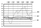
- FIG. 10 is a graph showing the results of Example 1.
- FIG. 11 is a graph showing the results of Example 2.
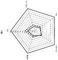
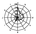
- FIG. 12 is a radar chart showing the result 1 of Example 3.
- FIG. 13 is a radar chart showing the result 2 of the third embodiment.
- FIG. 14 is a radar chart showing the result 3 of the third embodiment.
- FIG. 15 is a radar chart showing the result 4 of the third embodiment.
- FIG. 16 is a radar chart showing the result 5 of Example 3.
- FIG. 17 is a radar chart showing the result 1 of the fourth embodiment.
- FIG. 18 is a radar
- the odor sensor according to Embodiment 1 includes a substance adsorption film that adsorbs at least one odor substance contained in air, and signal conversion that measures physical, chemical, or electrical characteristics of the substance adsorption film after adsorbing the substance.
- An odor sensor including at least two sensor elements, wherein the substance adsorbing film includes a conductive polymer and a dopant that modifies a substance property of the conductive polymer, Each of the sensor elements is provided with the substance adsorption film having a different ratio of the basic skeleton and the dopant.
- the substance adsorbing film can be modified in film characteristics by the dopant, and each substance adsorbing film selectively adsorbs a certain substance selectively.
- a change in physical, chemical, or electrical characteristics due to the substance adsorbed on the surface of the substance adsorbing film can be detected, and the adsorption state of the substance can be measured based on the change.
- the term “smell” includes a specific molecule alone or a group of molecules composed of different molecules that can be acquired as olfactory information by a human or a living organism including the same.
- the signal converter measures the state of adsorption of odorous substances on the substance adsorption film, and measures changes in physical, chemical, or electrical characteristics of the substance adsorption film due to adsorption of odorous substances to the substance adsorption film.
- “adsorption state of odorous substance on substance adsorption film” includes, for example, “adsorption amount of odorant substance on substance adsorption film” as a concept.
- the physical, chemical, or electrical properties of the material adsorption film change due to the increase or decrease in the amount of adsorption of the odorous substance on the substance adsorption film. By measuring the amount of change, adsorption of the odorous substance to the substance adsorption film is performed.
- “physical, chemical, or electrical characteristics” specifically include frequency changes, optical characteristics changes (absorption wavelength changes, absorbance changes, refractive index changes, etc.), surface acoustic waves, etc. Physical characteristics such as a change in speed, electrochemical characteristics such as electrochemical impedance change and oxidation-reduction potential change, and electrical characteristics such as charge coupling, gate voltage, impedance, resonance frequency, and band gap.
- FIG. 1 is a sectional view of a sensor element 101 of the present invention.
- the sensor element 101 is provided on the surface of the sensor main body 102 and the sensor main body 102, and a substance adsorption film 103 that adsorbs an odor substance (chemical substance) is provided on the surface.
- the sensor main body 102 is provided on the substrate 110 in FIG.
- an excitation electrode (not shown) may be arranged on the opposite surface.
- the substance adsorbing film 103 is a thin film made of ⁇ -electron conjugated polymer, and the ⁇ -electron conjugated polymer thin film can contain at least one kind of inorganic acid, organic acid or ionic liquid as the dopant 105.
- the sensor main body 102 is provided so as to function as a signal conversion unit (transducer) that measures the adsorption state of a substance by measuring changes in physical, chemical, or electrical characteristics due to the substance adsorbed on the surface of the substance adsorption film. It has been.
- the physical, chemical or electrical elements include quartz crystal sensor (QCM), surface acoustic wave sensor, field effect transistor (FET) sensor, charge coupled device sensor, MOS field effect transistor sensor, metal oxide semiconductor sensor, organic A sensor such as a conductive polymer sensor or an electrochemical sensor is not particularly limited, and various sensors can be appropriately used depending on the purpose of the occasion.
- the structure of the element can take various structures depending on the detection purpose of the sensor. For example, in the case of a crystal resonator, a type in which normal electrodes are attached to both sides may be used, or a single-sided electrode having a high Q value may be used as a separation electrode.
- the ⁇ -electron conjugated polymer used as the substance adsorbing film 103 is not particularly limited, but a so-called ⁇ -electron conjugated polymer such as polypyrrole and derivatives thereof, polyaniline and derivatives thereof, polythiophene and derivatives thereof, polyacetylene and derivatives thereof, polyazulene and derivatives thereof, and the like.
- a polymer having a molecule as a skeleton is convenient.
- such a ⁇ -electron conjugated polymer is oxidized and the skeleton polymer itself becomes a cation, and exhibits conductivity by including an anion as a dopant.
- a neutral ⁇ -electron conjugated polymer having no dopant can also be selected as the substance adsorbing film.
- dopants include chlorine ions, chlorine oxide ions, bromine ions, sulfate ions, nitrate ions, borate ions and other inorganic ions, alkylsulfonic acid, benzenesulfonic acid, organic acid anions such as carboxylic acid, and polyacrylic acid. And polymer acid anions such as polystyrene sulfonic acid.
- the neutral ⁇ electron conjugated polymer contains a salt such as salt, an ionic compound containing both a cation and an anion such as an ionic liquid. It is also possible to use a method in which doping is performed in chemical equilibrium by coexisting.
- the ionic liquid that can be used here is not particularly limited, but examples thereof include pyridine-based, alicyclic amine-based, and aliphatic amine-based ionic liquids depending on the type of cation.
- Various structures can be synthesized by selecting the type of anion to be combined therewith.
- Examples of cations include ammonium-based, phosphonium-based ions and inorganic ions such as imidazolium salts and pyridinium salts.
- anions examples include halogen ions such as bromide ions and triflate, boron ions such as tetraphenylborate, and phosphorus ions such as hexafluorophosphate.
- the content of the dopant in the ⁇ -electron conjugated polymer is in the range of 0.01 to 5, preferably 0.1 when the state in which one molecule of the dopant enters two repeating units forming the high dopant is 1. It may be adjusted to a range of ⁇ 2. If the value is below the minimum value in this range, the characteristics of the film disappear, and if the dopant is contained above the maximum value, the effect of the adsorption characteristics of the polymer itself disappears. Besides being difficult, the durability of the film is greatly reduced because the dopant, which is usually a low molecular weight substance, becomes the dominant film. Therefore, if it is the above-mentioned range, it is possible to maintain suitably the detection sensitivity of the chemical substance as an odor substance.
- the thickness of the substance adsorbing film can be appropriately selected according to the characteristics of the substance to be adsorbed.
- the thickness may be in the range of 10 nm to 10 ⁇ m, and preferably 50 nm to 800 nm.
- the film thickness is less than 10 nm, sufficient sensitivity cannot be obtained.
- it since it will exceed the upper limit of the weight which a sensor element can measure if it exceeds 10 micrometers, it is unpreferable.
- ⁇ Production method of material adsorption film> As a method for producing the substance adsorbing film 103, for example, after diluting the solvent stock solution with various solvents, adjusting the film solution by dissolving the dopant component, and then dropping the solution onto the surface of the sensor element using a microdispenser or the like as appropriate.
- a film forming method can be selected to form a film.
- film liquid coating by ink jet can also be employed.
- FIG. 4 is a schematic diagram of the odor sensor 100 and an odor measurement system 1000 of the present invention described later.
- the odor sensor 100 includes the sensor element 101 described above.
- the odor sensor 100 of the present invention has a plurality of sensor elements 101, it is possible to adsorb substances having various characteristics by changing the configuration of the substance adsorption film 103 provided on the surface thereof, for example, for each element.
- the combination of the elements can be variously changed according to the purpose of detection.
- the entire substance recognition pattern can be performed, thereby showing the adsorption pattern related to a group of odorous substances.
- odor sensors usually have a single probe for detecting odor-causing substance molecules. In such a case, only qualitative or quantitative measurement of odor substance molecules can be performed.
- the odor sensor of the present invention is provided with a plurality of sensor elements.
- each sensor element can be configured to exhibit a reaction specific to the molecule to be acted on by providing substance adsorption films having different characteristics on the surface, and further to each target molecule. It is possible to adjust the degree of the action.
- all the sensor elements used can have the same element structure, that is, an array structure including only a QCM sensor in the case of a QCM detection system, and a sensor element array structure including only an FET sensor in the case of an FET detection system. is there. Or you may comprise an element array by coexisting several types among the element structures mentioned above.
- the ⁇ -electron conjugated polymer used as the substance adsorbing film 103 may have a single-film array structure, and a sensor array in which only the dopant is changed for each element may be used. Different configurations may be adopted. In the latter case, the dopant can be arbitrarily arranged in the sensor array independently of the ⁇ -electron conjugated polymer.
- an array structure in which a substance adsorbing film is not formed in one or more sensor elements may be used. Since these non-film-forming elements can be used as a reference, it is possible to ensure detection accuracy.
- the odor sensor of the present invention can be used by combining the configurations of the sensor element body and the substance adsorption film, various sensor configurations can be made according to the characteristics of the substance to be detected.
- Sensor elements coated with different substance adsorption films 103 interact differently with the odor-causing substance that is the object to be measured.
- the sensors provided with these different substance adsorbing films on the array it is possible to detect and analyze the frequency change of each sensor element and to qualitatively and quantitatively analyze the odor factor.
- odorous substance is adsorbed and detected as information in the X-axis direction and Y-axis direction as the arrangement rule of each sensor element having different substance adsorption films disposed on the substrate.
- a qualitative odor pattern consisting of at least three dimensions of the sensor array information and the frequency change (adsorption characteristics and the degree of mutual right and left) of the same element group.
- the sensor element and the excitation electrode can be formed of any conductive material.
- conductive material examples include gold, silver, platinum, chromium, titanium, aluminum, nickel, nickel alloys, inorganic materials such as silicon, carbon, carbon nanotubes, and organic materials such as conductive polymers such as polypyrrole and polyaniline. it can.
- each sensor constituting each array can have a slightly different interaction.
- each crystal resonator If the resonance frequency of each crystal resonator is the same, it is also attempted to change the thickness by changing the thickness of the odor adsorbing film.
- elements having different resonance frequencies for example, an overtone mode in which the thickness of the quartz substrate is changed.
- a silicon substrate As the type of substrate, a silicon substrate, a substrate made of quartz crystal, a printed wiring substrate, a ceramic substrate, a resin substrate, or the like can be used.
- the substrate is a multilayer wiring substrate such as an interposer substrate, and excitation electrodes for mounting the quartz substrate, mounting wiring, and electrodes for energization are arranged at arbitrary positions. In order to conduct to an electronic circuit board or the like, for example, it is connected to a bump.
- the convex shape of the crystal resonator is smaller, encapsulates energy in the resonator, prevents interference between each resonator in the substrate, and at the same time, the Q value is expected to improve. This is a more preferable shape.
- one side is a separate excitation electrode (electrode for inputting vibration voltage), and the conductive film is opposite to the excitation electrode It can be set as the structure installed in the position where a surface opposes.
- the Q value and conductance can be improved by the effect of confining vibration energy, and even if the device is downsized, the vibration energy does not decrease, and a crystal resonator that is less susceptible to external contact interference can be obtained.
- the sensitivity is improved by improving the S / N ratio.
- the QCM sensor formed here has a structure called reverse mesa type or convex type, which is suitable for miniaturization because close surface mounting is possible.
- a convex type suitable for smaller size is taken as an example, but if there is a more optimal shape, it can be selected.
- the elliptical shape can improve the sensitivity (Q value) of the QCM element, and a more optimal one can be used in consideration of the cost.
- the size of the sensor body (signal conversion unit) is preferably the same as or smaller than the range where the substance adsorption film on the surface is applied. Due to the current technical limitations, there is a limit to the reduction in the application area of the substance adsorption film, so even if it is configured to allocate multiple sensor bodies (signal converters) to the area where the substance adsorption film is applied good.
- Examples of the structure of the sensor body (signal conversion unit) include a transistor array composed of a plurality of fine MOSFETs and a charge coupled device array. From the viewpoint of ease of measurement and miniaturization, the charge coupled device An array is particularly preferred.
- the odor sensor of the present invention can detect any odor substance with almost no limitation. Further, with such a configuration, it is only necessary to provide as many sensor elements as necessary to detect as many substances as desired for detection and identification, thereby quantifying and analyzing a plurality of odor substances contained in the odor itself. Measured qualitatively, this odor can be measured as a whole.
- the sensor element 101 arranged in the odor sensor 100 can be selected according to the substance to be measured.
- the substance adsorption film 103 having characteristics specific to the odor substance to be detected and measured and the sensor element 101 by the sensor body 102 can be appropriately selected and arranged.
- Such a configuration makes it possible to measure any odorous substance present in the gas as a sample. Furthermore, in the past, it was only possible to measure the intensity of the odor unique to each molecule based on the amount of individual molecules contained in the odor substance. However, the odor substance measured from the combination of sensor detection patterns is a specific odor. In other words, it becomes possible to measure and identify the odor itself composed of a plurality of odor substances.
- the detection unit 1001 since the detection unit 1001 includes the odor sensor 100 having an array structure, the number of sensors that act specifically on specific substance molecules, the arrangement thereof, and the type of sensor are determined. It is possible to determine after designing the reaction pattern in the entire array when acting. By storing the reaction pattern in the odor information storage unit 1004 in advance, it becomes possible to collate with the reaction in the odor sensor 100 with respect to each odor substance, so that an aggregate of a plurality of odor substances can be measured, thereby It becomes possible to measure an odor itself containing a plurality of odor substances that could not be realized by a conventional odor sensor.
- the odor sensor 100 provided in the detection unit 1001 of the odor measurement system 1000 of the present invention shown in FIG. 4 is brought into contact with the odor substance to be measured.
- molecules of the odorous substance are taken in, and the substance is adsorbed on the substance adsorption film 103 of the sensor element 101.
- the odor sensor 100 has a multi-array structure in which at least two or more sensor elements 101 are arranged.
- each sensor element 101 interacts with a specific degree for each target odor substance, and interacts with various odor-causing substances contained in the odor.
- a gas containing an odorous substance taken into the array portion is brought into contact with each other, and the interaction result indicated by each sensor is acquired as data.
- This interaction data is physical information output from the transducer unit, such as a light emission response, a change in electrical resistance, or a change in vibration frequency, depending on the sensor used.
- Signal information is captured by the measurement unit 1002 as signal information including the positional information of the sensor that reacts on the sensor array and the strength of the interaction in association with the specific odor factor to be measured. I do.
- the data processing unit 1003 performs data processing for associating the measurement data pattern with the element array information.
- the measurement data pattern that has been subjected to this data processing can be visualized with respect to the odor itself, for example, by reproducing the output pattern as shown in FIG. 4 based on the difference in the light emission response or displaying it as matrix information of the matrix. Alternatively, recognition can be facilitated.
- this data processed interaction pattern information can be stored in a database by storing, for example, an odor information storage unit together with information data related to odors, and can be used when reproducing odors.
- FIG. 5 is a schematic view of the odor sensor array 205 and a partially enlarged view thereof.
- a partial enlarged view including the odor sensor 200 arranged in the upper right corner of the odor sensor array 205 and the vicinity thereof is shown in a circle.
- each of the nine sensor elements 201 has a substance adsorption film 203 different from each other.
- the odor sensor array 205 is obtained by arranging two or more odor sensors 200 including the sensor element 201.
- the odor sensor 200 can be the same as the odor sensor 100 described in the first embodiment, and the substance adsorption film 203 that adsorbs the odor substance and the adsorption state of the odor substance on the substance adsorption film 203 are determined.
- Two or more sensor elements 201 having a signal conversion unit are included.
- the substance adsorbing film 203 includes a conductive polymer and a dopant that changes the substance characteristics of the conductive polymer.
- the substance adsorption films 203 included in the two or more sensor elements have different dopant content ratios relative to the conductive polymer.
- the odor sensor array 205 is formed by arranging two or more of the odor sensors described above, the odor substance adsorption state at two or more different positions can be detected. Thereby, the positional information of the odor substance or the gas containing the odor substance can be detected.
- the odorous substance or the odorous substance is included based on the difference in the adsorption amount of the odorous substance in each odor sensor.
- the moving direction of the gas can be grasped. That is, the moving direction of the odorous substance can be detected. For example, by detecting the so-called “burn odor” that occurs in the smoldering state before ignition with the odor sensor array 205, it is possible to detect from which direction the burn odor has moved, and to identify the source of the fire It can be useful for.
- the measurement values of the odor sensors in the odor sensor array 205 can be recorded in time series. Thereby, it is possible to grasp the distance along which the odorous substance has moved over time. Naturally, the concentration distribution of the odor substance at the position corresponding to each odor sensor of the odor sensor array 205 and its transition process can also be grasped.
- the odor sensors 200 included in the odor sensor array 205 may be the same or different. However, when the movement direction of a specific odor substance is grasped, at least one kind of odor sensor 200 included in each odor sensor 200 is used. It is preferable that the odor sensors 200 have the substance adsorption film 203 in common. More preferably, the odor sensors 200 have a combination of the substance adsorption films 203 of the odor sensors 200 in common. Furthermore, it is preferable that each odor sensor 200 is the same.
- the overall shape of the odor sensor array 205 is not particularly limited, for example, as shown in FIG. 5, the sensor elements 201 of the odor sensors are arranged in a plane, and the odor sensors 200 are arranged in a plane.
- a flat odor sensor array 205 may be used. If the overall shape of the odor sensor array 205 is a flat plate, it can be easily installed in an arbitrary flat place such as a wall, ceiling, or floor.
- the overall shape of the odor sensor array 205 may be cylindrical or spherical with the surface covered with the odor sensor 200. In this way, by making the entire shape like a cylinder or a sphere, the moving direction of the odorous substance can be grasped three-dimensionally.
- the manufacturing method of the odor sensor array 205 is not particularly limited.
- a transistor sensor array such as a charge coupled device array or MOSFET is used as a sensor body (signal conversion unit)
- the transistor sensor array corresponds to the odor sensor.
- the section 207 of the range to be processed and the section 207 are further divided into the small fraction sections 208 of the range corresponding to the sensor element 201, and different substance adsorption films 203 are formed in the respective small fraction sections 208. it can.
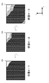
- odor sensor array 205 An application example of the odor sensor array 205 will be described with reference to FIGS. Here, the example which visualized the measurement result in each odor sensor 200 when water and sake are adsorbed or desorbed using the flat odor sensor array 205 is shown.
- FIG. 6 is an explanatory view showing a change in the adsorption state when water is adsorbed on the substance adsorption film.
- FIG. 7 is an explanatory diagram showing changes in the adsorption state when water is desorbed from the substance adsorption film.
- FIG. 8 is an explanatory diagram showing changes in the adsorption state when sake is adsorbed on the substance adsorption film.
- FIG. 9 is an explanatory view showing a change in the adsorption state when sake is desorbed from the substance adsorption film.
- odor sensor arrays 215, 225, 235, and 245 are installed on the XY plane, and water or sake as a sample is sampled at the lower left circle position of the odor sensor arrays 215 and 235 in the figure.
- positions in the containers 216,236 is shown.
- the measurement results immediately after placing water or sake are shown as “state 1-1” and “state 3-1” in FIGS. 6 and 8, respectively.
- the measurement results immediately after removing water or sake are shown as “state 2-1” and “state 4-1” in FIGS. 7 and 9, respectively.
- a change in physical, chemical, or electrical characteristics of each substance adsorbing film 203 caused by adsorption of the odor substance to each substance adsorbing film 203 is Depending on the magnitude of the change amount, for example, it can be expressed by color or by shading.
- the measurement results are shown in light and shade according to the magnitude of the change amount, and when the change amount is zero (no change) or small, it is thin, and when the change amount is medium, the measurement result is medium.
- the shading is shown in three stages for simplicity, but of course, threshold values such as a change in color tone and a shading change can be set as appropriate.
- the amount of change is zero (no change) or small, but in the state 1-2 after a lapse of a certain time, the region where the amount of change is moderate is from the lower left. Up to about 2/3, the region where the amount of change is large progresses from the lower left to about 1/3.
- the amount of change is large in most of the odor sensor array 215, and the range in which the odor substance is adsorbed on the substance adsorption film 203 of each odor sensor 200 is the odor sensor. It can be seen that it extends over most of the array 215. Further, by visualizing the change in time series as in the state 1-1 to the state 1-3, the moving direction of the odorous substance can be determined.
- each odor sensor 200 can detect an odor pattern
- the odor sensor array 215, 225, 235, 245 provided with the odor sensor 200 can also detect the movement of two or more odor substances. Further, when two or more odor substances are combined on the odor sensor array 215, 225, 235, 245, the odor sensor in the area where two or more odor substances are combined is not less than two of the combined odor sensors. The odor pattern corresponding to the odor substance can be detected. By applying this, for example, it becomes possible to qualitatively and quantitatively evaluate and visualize what kind of odor will result when a fragrance is blended.
- Example 1 ⁇ Material Adsorption Film by Combination of Conductive Polymer and Ionic Liquid> 1) Adjustment of substance adsorption film
- polyaniline was used as the conductive polymer, and the film liquid was adjusted as follows.
- the dopant component was weighed to a molar ratio of 1.0 with respect to 2 units of aniline, and the following dopant component was added. Dissolved in NMP.
- System 1 2% polyaniline only
- System 5 1% 1-ethyl 3-methylimidazolium p-toluenesulfonic acid (anionic dopant) was added to 2% polyaniline and mixed to prepare.
- Example 2 (Comparative Example) ⁇ Testing with Film Formation Using Single Ionic Liquid> A substance adsorbing film was prepared and tested with an ionic liquid alone as follows.
- Example 3 Film liquid adjustment The following ionic liquid was mixed as a dopant using 0.4% polyaniline to adjust the film liquid.
- A 1-butyl-3-methylimidazolium chloride (Wako Pure Chemical Industries, Ltd. 027-15201)
- B 1-ethyl-3-methylimidazolium p-toluenesulfonate (Wako Pure Chemical Industries 051-07311)
- C Sodium dodecylbenzenesulfonate (soft type) (mixture) (62%, water-wet product) (Tokyo Kasei (TCI) D1238)
- Membrane 1 0.4% polyaniline + A Film 2: 0.4% polyaniline + B Film 3: 0.4% polyaniline + B + 0.5% additive Film 4: 0.4% polyaniline + B + 2.0% additive Film 5: 0.4% polyaniline + C + 0.4% polyethylene dioxythiophene And performed in the same manner.
- FIGS. 12 to 16 are radar charts showing the measurement results of the sample gases of the films 1 to 5 described above. As shown in the chart, it was found that by mixing an ionic liquid as a dopant with polyaniline as a conductive polymer, the material adsorption characteristics of the film change depending on the mixing conditions.
- Example 4 the instant coffee and drip coffee odor substance aggregates are adsorbed to the substance adsorption films a to 1 using polyaniline as the conductive polymer and the following ionic liquids La to Ll as the dopant, respectively. evaluated.
- the preparation of the membrane liquid, sample preparation, and flow measurement are substantially the same as those in Example 1 except that the ionic liquid is different.
- Ionic liquid La 1-butyl-3-methylimidazolium chloride
- Ionic liquid Lb 1-ethyl-3-methylimidazolium p-toluenesulfonate
- Ionic liquid Lc Methanesulfonic acid
- Ionic liquid Ld Ammonium benzoate
- Ionic liquid Le Lauric acid Sodium ionic liquid
- Lf (+)-3-bromocamphor-8-ammonium sulfonate ionic liquid
- Lg phosphoric acid ionic liquid
- Lh 1-ethyl-3-methylimidazolium sulfate ionic liquid
- Li acetic acid ionic liquid
- Lj boro Acid
- Ionic liquid Lk Phenol Ionic liquid Ll: Benzenesulfonic acid
- Sample gas was sequentially introduced in a cycle in which sample gas was introduced into the chamber, allowed to stand for 300 seconds, and then air was introduced for 300 seconds. In addition, by introducing air for 300 seconds, the sample gas in the chamber is driven out and refreshed.
- FIG. 17 is a radar chart showing the result 1 of Example 4, and shows the result when the odorant aggregate of instant coffee is adsorbed on the substance adsorption films a to l.
- FIG. 18 is a radar chart showing the result 2 of Example 4, which shows the result when the odor substance aggregate of drip coffee is adsorbed on the substance adsorption films a to l.
- the sensor element with the substance adsorption film of the odor sensor according to the present invention is a state in which a plurality of substances are mixed in a complicated manner. Even so, it is possible to provide a so-called “second nose” that the odor itself can be detected based on the detection pattern.
- the present invention is not intended to be used as a substitute for a gas sensor frequently used in the chemical industry or the like.
- the quality control of a product having a complex odor composed of a large number of chemical species such as foods and beverages. It can be used for patterning and analysis of odors in various fields, such as sensory testing of odor products, odor design for stationery and daily necessities. Thereby, sensing based on smell is possible in various situations.
- the odor sensor and the odor measurement system of the present invention are used to record the odor by measuring the odor pattern, and based on this, an odor reproduction system in the virtual space is provided. It is also possible to display the smell as an image in online sales where the user cannot feel the smell.
Landscapes
- Chemical & Material Sciences (AREA)
- Health & Medical Sciences (AREA)
- Life Sciences & Earth Sciences (AREA)
- Physics & Mathematics (AREA)
- Immunology (AREA)
- Pathology (AREA)
- Analytical Chemistry (AREA)
- Biochemistry (AREA)
- General Health & Medical Sciences (AREA)
- General Physics & Mathematics (AREA)
- Engineering & Computer Science (AREA)
- Electrochemistry (AREA)
- Chemical Kinetics & Catalysis (AREA)
- Power Engineering (AREA)
- Medicinal Chemistry (AREA)
- Combustion & Propulsion (AREA)
- Food Science & Technology (AREA)
- Molecular Biology (AREA)
- Microelectronics & Electronic Packaging (AREA)
- Acoustics & Sound (AREA)
- Investigating Or Analyzing Materials By The Use Of Fluid Adsorption Or Reactions (AREA)
- Investigating Or Analyzing Materials By The Use Of Electric Means (AREA)
- Investigating Or Analyzing Materials By The Use Of Ultrasonic Waves (AREA)
- Investigating Or Analysing Materials By Optical Means (AREA)
Abstract
Description
まず、本発明の実施形態1に係る匂いセンサについて説明する。実施形態1に係る匂いセンサは、空気中に含まれる少なくとも一つ以上の匂い物質を吸着する物質吸着膜と、前記物質を吸着後の物質吸着膜の物理、化学又は電気特性を測定する信号変換部とを具備する少なくとも2つのセンサ素子とを含む匂いセンサであって、当該物質吸着膜は、導電性高分子と、前記導電性高分子の物質特性を変性させるドーパントとを含み、前記少なくとも2つのセンサ素子は、前記基本骨格と前記ドーパントの割合が異なる前記物質吸着膜をそれぞれ設けていることを特徴とするものである。
以下、図を用いてセンサ素子の説明を行う。
物質吸着膜103の製造方法としては、例えば、溶媒原液を種々溶媒で希釈した後、ドーパント成分を溶解することで膜液を調整した後、マイクロディスペンサなどを用いてセンサ素子表面に滴下する等適宜膜形成方法を選択して製膜することができる。物質吸着膜103の製造にはインクジェットによる膜液塗布も採用することができる。
次にセンサ全体について説明する。
次に、本システムで用いられる匂い測定方法に関して説明する。
<匂いセンサ配列体>
次に、実施形態2に係る匂いセンサ配列体205について説明する。図5は、匂いセンサ配列体205の模式図及びその部分拡大図である。図5中、匂いセンサ配列体205の最も右上に配置された匂いセンサ200及びその近傍を含む部分拡大図を円内に示す。図5では、9個のセンサ素子がY方向に3個、X方向に3個で平面状に配列された匂いセンサ200が、Y方向に5個、X方向に6個で合計30個平面状に配列されている場合を示している。各匂いセンサ200において、9個のセンサ素子201は、いずれも互いに異なる物質吸着膜203を有している。
図6~図9を参照しながら、匂いセンサ配列体205の一応用例について説明する。ここでは、平板状の匂いセンサ配列体205を用いて、水と日本酒とをそれぞれ吸着又は脱着させた場合の各匂いセンサ200における測定結果を可視化した例を示す。
1)物質吸着膜の調整
本実施例では、導電性高分子としてポリアニリンを用い、以下の通り膜液の調整を行った。
系5:2%ポリアニリンに1%の1エチル3メチルイミダゾリウムp-トルエンスルホン酸(アニオン系ドーパント)を添加、混合して調整した。
ドーパント=1%1エチル3メチルイミダゾリウムp-トルエンスルホン酸(アニオン系ドーパント)
ガス:空気、H2O、エタノール、NH3
サンプルガスの濃度はそれぞれ10ppmとした。
本実験の結果を図10に示す。縦軸はセンサが反応したときの周波数変化を示し、横軸は時間を示す。グラフに示す通り、ドーパント含有物質吸着膜を設けている系5のセンサは各サンプルに対して特異的に反応していることが示された。
以下の通りイオン性液体単体で物質吸着膜を作成、試験を行った。
系4:1-ブチル-3-メチルイミダリゾウム=クロリド0.00963gを1mLのエタノールに溶解し、更にその後エタノールで2倍に希釈した。
上記それぞれの系の原液1μLをQCMセンサ表面にマイクロピペットを用いて滴下した。次いで乾燥炉100℃、10分で乾燥し製膜した。
ガス:NH3(10%NH3及びガラスディッシュに水をいれて湿度調整を行った)、香料(ムスク1mLを40mLエタノールで溶解したもの)、空気
フロー測定:実施例1と同様の手順で行った。
本試験の結果を図11に示す。グラフの縦軸、横軸は図10と同様である。グラフに示されている通り、多少の反応はあるものの、特定の物質に特異的な反応を示すところまでではなかった。
1)膜液調整
0.4%ポリアニリンを用いて下記イオン液体をドーパントとして混合して膜液を調整した。
B:1-エチル-3-メチルイミダゾリウムp-トルエンスルホン酸塩(和光純薬工業051-07311)
C:ドデシルベンゼンスルホン酸ナトリウム(ソフト型)(混合物)(62%、水湿潤品)(東京化成(TCI)D1238)
膜2:0.4%ポリアニリン+B
膜3:0.4%ポリアニリン+B+0.5%添加剤
膜4:0.4%ポリアニリン+B+2.0%添加剤
膜5:0.4%ポリアニリン+C+0.4%ポリエチレンジオキシチオフェン
調整手順は実施例1と同様にして行った。
実施例1と同様にして行った。
サンプルガス:H2O、エタノール、NH3(15ppm)、ウイスキー、日本酒
フロー測定:これらサンプルを揮発させて実施例1と同様に空気でリフレッシュしながらガスをチャンバー内に流入させて測定を行った。
結果を図12から図16に示す。図12~図16は上記膜1~5の各サンプルガスの測定結果を示すレーダーチャートである。該チャートが示すように、導電性高分子であるポリアニリンにドーパントであるイオン液体を混合することにより、その混合条件に応じて膜の物質吸着特性が変わることが分かった。
実施例4では、導電性高分子としてポリアニリン、ドーパントとして下記イオン液体La~Llをそれぞれ用いた物質吸着膜a~lに対して、インスタントコーヒー及びドリップコーヒーの匂い物質集合体を吸着させた場合について評価した。なお、膜液の調製、及びサンプル作成やフロー測定は、イオン液体が異なること以外は、実質的に実施例1と同様である。
原料溶液としての2%ポリアニリンをNMP(N-メチル-2-ピロリドン)で10倍に希釈して、0.2%ポリアニリン溶液を調製した。下記列挙のイオン液体をそれぞれ量り取り、NMPに溶解して、各イオン液体(ドーパント)成分のアニリン2ユニットに対するモル比が1.0となるようにイオン液体La~Llを調製した。次いで、調製した0.2%ポリアニリン溶液と、イオン液体La~Llを、体積比1:1で混合し、各膜液を調製した。
イオン液体Lb:1-エチル-3-メチルイミダゾリウムp-トルエンスルホネート
イオン液体Lc:メタンスルホン酸
イオン液体Ld:アンモニウムベンゾエート
イオン液体Le:ラウリン酸ナトリウム
イオン液体Lf:(+)-3-ブロモカンファー-8-スルホン酸アンモニウム
イオン液体Lg:リン酸
イオン液体Lh:1-エチル-3-メチルイミダゾリウム硫酸塩
イオン液体Li:酢酸
イオン液体Lj:ホウ酸
イオン液体Lk:フェノール
イオン液体Ll:ベンゼンスルホン酸
調製した各膜液0.1μLを、QCMセンサの表面に滴下して塗布し、乾燥炉にて温度100℃で10分間乾燥して、物質吸着膜a~lをそれぞれ有するセンサ素子を作成した。
温度25℃、湿度55%
サンプルガス:インスタントコーヒー及びドリップコーヒーの粉末を、それぞれ密閉容器に一定時間載置し、密閉容器内の気体をサンプルガスとした。
サンプルガスを導入した場合のQCMセンサの周波数変化のピーク値をそれぞれ結果1又は結果2の測定値として、図17又は図18のレーダーチャートに示した。図17は、実施例4の結果1を示すレーダーチャートであり、インスタントコーヒーの匂い物質集合体を物質吸着膜a~lに吸着させた場合の結果を示す。図18は実施例4の結果2を示すレーダーチャートであり、ドリップコーヒーの匂い物質集合体を物質吸着膜a~lに吸着させた場合の結果を示す。
102:センサ素子本体 103,203:物質吸着膜
205,215,225,235,245:匂いセンサ配列体
207:区画 208:小分画部
216,236:サンプル容器 1000:匂い測定システム
1001:検出部 1002:データ処理部
1003:解析部
Claims (20)
- 匂い物質を吸着する物質吸着膜と、
前記匂い物質の前記物質吸着膜への吸着状況を判断する信号変換部と、
を有するセンサ素子を2つ以上含み、
前記物質吸着膜は、導電性高分子と、前記導電性高分子の物質特性を変化させるドーパントと、を含み、
2つ以上の前記センサ素子が有する各々の前記物質吸着膜は、前記導電性高分子に対する前記ドーパントの含有割合がそれぞれ異なる、匂いセンサ。 - 前記信号変換部は、前記匂い物質が前記物質吸着膜へ吸着することに起因する前記物質吸着膜の物理的、化学的、又は電気的特性の変化を測定することにより吸着状況を判断するものである、
請求項1に記載の匂いセンサ。 - 前記導電性高分子が、π電子共役高分子を含む、
請求項1又は2に記載の匂いセンサ。 - 前記π電子共役高分子が、ポリピロール及びその誘導体、ポリアニリン及びその誘導体、ポリチオフェン及びその誘導体、ポリアセチレン及びその誘導体、並びにポリアズレン及びその誘導体からなる群より選択される、
請求項3に記載の匂いセンサ。 - 前記ドーパントが、前記物質吸着膜の吸着特性を変化させる、
請求項1から請求項4のうちいずれか1項に記載の匂いセンサ。 - 前記ドーパントが、無機イオンである、
請求項1から請求項5のうちいずれか1項に記載の匂いセンサ。 - 前記無機イオンが、塩素イオン、塩素酸化物イオン、臭素イオン、硫酸イオン、硝酸イオン、及びホウ酸イオンからなる群より選択される、
請求項6に記載の匂いセンサ。 - 前記ドーパントが、有機酸アニオンである、
請求項1から請求項5のうちいずれか1項に記載の匂いセンサ。 - 前記有機酸アニオンが、アルキルスルホン酸、ベンゼンスルホン酸、及びカルボン酸からなる群より選択される、
請求項8に記載の匂いセンサ。 - 前記ドーパントが、高分子酸アニオンである、
請求項1から請求項5のうちいずれか1項に記載の匂いセンサ。 - 前記高分子酸アニオンが、ポリアクリル酸、又はポリスチレンスルホン酸である、
請求項10に記載の匂いセンサ。 - 前記ドーパントが、塩である、
請求項1から請求項5のうちいずれか1項に記載の匂いセンサ。 - 前記ドーパントが、イオン液体である、
請求項1から請求項5のうちいずれか1項に記載の匂いセンサ。 - 前記イオン液体が、ピリジン系、脂環族アミン系、又は脂肪族アミン系のイオン液体である、
請求項13に記載の匂いセンサ。 - センサ素子を含む匂いセンサが2つ以上配列され、
前記匂いセンサは、
前記匂い物質を吸着する物質吸着膜と、
前記匂い物質の前記物質吸着膜への吸着状況を判断する信号変換部と、
を有する前記センサ素子を2つ以上含み、
前記物質吸着膜は、導電性高分子と、前記導電性高分子の物質特性を変化させるドーパントと、を含み、
2つ以上の前記センサ素子が有する各々の前記物質吸着膜は、前記導電性高分子に対する前記ドーパントの含有割合がそれぞれ異なる、匂いセンサ配列体。 - 2つ以上配列された前記匂いセンサが、それぞれの前記匂いセンサにおける前記匂い物質の吸着量の違いに基づいて、前記匂い物質が接近してきた方向を検知する、
請求項15に記載の匂いセンサ配列体。 - 2つ以上の前記匂いセンサが、それぞれ同じ組み合わせの前記物質吸着膜を有する、
請求項15又は請求項16に記載の匂いセンサ配列体。 - 2つ以上の前記匂いセンサにおいて、それぞれの前記センサ素子の配列が同じである、
請求項15から請求項17のうちいずれか1項に記載の匂いセンサ配列体。 - 2つ以上の前記センサ素子が平面状に配列され、
2つ以上の前記匂いセンサが平面状に配列された、
請求項15から請求項18のうちいずれか1項に記載の匂いセンサ配列体。 - 匂い物質と相互作用する2つ以上のセンサ素子を含む匂いセンサを有する検出部と、
前記センサ素子と前記匂い物質との相互作用に基づく電気特性をパターン化して視認化するデータ処理部、
前記パターンを解析、認識する解析部と、
を含み、
前記匂いセンサは、
前記匂い物質を吸着する物質吸着膜と、
前記匂い物質の前記物質吸着膜への吸着状況を判断する信号変換部と、
を有する前記センサ素子を2つ以上含み、
前記物質吸着膜は、導電性高分子と、前記導電性高分子の物質特性を変化させるドーパントと、を含み、
2つ以上の前記センサ素子が有する各々の前記物質吸着膜は、前記導電性高分子に対する前記ドーパントの含有割合がそれぞれ異なる、匂い測定システム。
Priority Applications (6)
| Application Number | Priority Date | Filing Date | Title |
|---|---|---|---|
| JP2017551540A JP6508689B2 (ja) | 2015-11-17 | 2016-02-22 | 匂いセンサおよび匂い測定システム |
| CN201680059047.2A CN108139344B (zh) | 2015-11-17 | 2016-02-22 | 气味传感器及气味测定系统 |
| HK18115424.4A HK1256338B (en) | 2015-11-17 | 2016-02-22 | Odor sensor and odor measurement system |
| EP16865943.1A EP3379240A4 (en) | 2015-11-17 | 2016-02-22 | ODOR SENSOR AND ODOR MEASUREMENT SYSTEM |
| US15/982,699 US11073491B2 (en) | 2015-11-17 | 2018-05-17 | Odor sensor and odor measurement system |
| US17/343,861 US11796497B2 (en) | 2015-11-17 | 2021-06-10 | Odor sensor and odor measurement system |
Applications Claiming Priority (2)
| Application Number | Priority Date | Filing Date | Title |
|---|---|---|---|
| PCT/JP2015/082326 WO2017085796A1 (ja) | 2015-11-17 | 2015-11-17 | 匂いセンサおよび匂い測定システム |
| JPPCT/JP2015/082326 | 2015-11-17 |
Related Child Applications (1)
| Application Number | Title | Priority Date | Filing Date |
|---|---|---|---|
| US15/982,699 Continuation US11073491B2 (en) | 2015-11-17 | 2018-05-17 | Odor sensor and odor measurement system |
Publications (1)
| Publication Number | Publication Date |
|---|---|
| WO2017085939A1 true WO2017085939A1 (ja) | 2017-05-26 |
Family
ID=58718666
Family Applications (2)
| Application Number | Title | Priority Date | Filing Date |
|---|---|---|---|
| PCT/JP2015/082326 Ceased WO2017085796A1 (ja) | 2015-11-17 | 2015-11-17 | 匂いセンサおよび匂い測定システム |
| PCT/JP2016/055082 Ceased WO2017085939A1 (ja) | 2015-11-17 | 2016-02-22 | 匂いセンサおよび匂い測定システム |
Family Applications Before (1)
| Application Number | Title | Priority Date | Filing Date |
|---|---|---|---|
| PCT/JP2015/082326 Ceased WO2017085796A1 (ja) | 2015-11-17 | 2015-11-17 | 匂いセンサおよび匂い測定システム |
Country Status (5)
| Country | Link |
|---|---|
| US (2) | US11073491B2 (ja) |
| EP (1) | EP3379240A4 (ja) |
| JP (2) | JP6508689B2 (ja) |
| CN (2) | CN108139344B (ja) |
| WO (2) | WO2017085796A1 (ja) |
Cited By (9)
| Publication number | Priority date | Publication date | Assignee | Title |
|---|---|---|---|---|
| JP2019052993A (ja) * | 2017-09-19 | 2019-04-04 | 株式会社東芝 | 分子検出装置及び分子検出方法 |
| JP2020041810A (ja) * | 2018-09-06 | 2020-03-19 | 日本精工株式会社 | ガスセンサ |
| JP2020046260A (ja) * | 2018-09-18 | 2020-03-26 | 株式会社東芝 | ケミカルセンサ用液膜材料及びケミカルセンサ |
| JP2020165971A (ja) * | 2019-03-29 | 2020-10-08 | 味の素株式会社 | 高分子組成物、キット、及び、物質吸着膜の形成方法 |
| JP2022516523A (ja) * | 2018-12-31 | 2022-02-28 | アリベール | 標的化合物の特性化方法(method for characterising target compounds) |
| JP2022045689A (ja) * | 2020-09-09 | 2022-03-22 | 環境電子株式会社 | 油類及びカビ臭の自動検出装置及び臭いセンサ付き魚類による毒物自動監視装置 |
| WO2023027120A1 (ja) * | 2021-08-27 | 2023-03-02 | パナソニックIpマネジメント株式会社 | 感応膜及びガスセンサ |
| WO2023067930A1 (ja) * | 2021-10-19 | 2023-04-27 | 株式会社レボーン | 検出装置、情報処理装置及びプログラム |
| US20230213429A1 (en) * | 2022-01-03 | 2023-07-06 | Opteev Technologies, Inc. | Systems and methods for detecting aerosolized viral particles |
Families Citing this family (44)
| Publication number | Priority date | Publication date | Assignee | Title |
|---|---|---|---|---|
| WO2017150214A1 (ja) * | 2016-02-29 | 2017-09-08 | 京セラ株式会社 | 検査装置及び検査システム |
| ES2983914T3 (es) * | 2016-05-27 | 2024-10-28 | Carrier Corp | Dispositivo de detección de gas y método de fabricación del mismo |
| JP2018155576A (ja) * | 2017-03-17 | 2018-10-04 | 太陽誘電株式会社 | 検出素子及び検出装置 |
| JP6976530B2 (ja) * | 2017-06-19 | 2021-12-08 | 株式会社アロマビット | 複合データ生成方法及び複合データ生成装置 |
| JP7212966B2 (ja) * | 2017-06-19 | 2023-01-26 | 株式会社アロマビット | 複合データ生成方法及び複合データ生成装置 |
| JP6943400B2 (ja) * | 2017-09-08 | 2021-09-29 | 株式会社アロマビット | 導電性高分子膜の作製方法 |
| FR3071061B1 (fr) * | 2017-09-14 | 2019-09-13 | Aryballe Technologies | Systeme de detection perfectionne pour nez electronique et nez electronique comprenant un tel systeme |
| JP7042067B2 (ja) * | 2017-12-04 | 2022-03-25 | 東芝ライフスタイル株式会社 | 衣類乾燥機 |
| JP7075826B2 (ja) * | 2018-06-15 | 2022-05-26 | 東芝ライフスタイル株式会社 | 冷蔵庫 |
| CN109115839B (zh) * | 2018-07-03 | 2020-11-20 | 华东师范大学 | 一种管内生长掺杂态或填充介孔聚苯胺气体传感器及制备方法 |
| JP7269559B2 (ja) * | 2018-07-12 | 2023-05-09 | 浜松ホトニクス株式会社 | 匂いセンサ及び匂いセンサの製造方法 |
| WO2020036171A1 (ja) * | 2018-08-17 | 2020-02-20 | 富士フイルム株式会社 | センサ |
| WO2020102880A1 (en) * | 2018-11-20 | 2020-05-28 | National Research Council Of Canada | Sensor platform |
| JP7391540B2 (ja) * | 2019-05-31 | 2023-12-05 | 浜松ホトニクス株式会社 | 匂いセンサ及び匂い検出方法 |
| EP3978899B1 (en) | 2019-06-03 | 2023-11-22 | I-PEX Inc. | Substance detection system and substance detection method |
| CN110320268B (zh) * | 2019-08-15 | 2021-10-29 | 杭州市中医院 | 通过味觉检测系统表征溶液中的味物质的方法 |
| CN110320269B (zh) * | 2019-08-15 | 2021-11-02 | 杭州市中医院 | 通过味觉检测系统检测溶液中的味物质的方法 |
| US12313579B2 (en) * | 2019-12-27 | 2025-05-27 | Aroma Bit, Inc. | Odor sensor, odor measurement system, and method for producing odor sensor |
| EP4089609A4 (en) | 2020-02-28 | 2023-06-28 | I-PEX Inc. | Information management system, information management method, and program |
| US11898988B2 (en) | 2020-03-17 | 2024-02-13 | Kabushiki Kaisha Toshiba | Molecular sensor, molecular detection device, and molecular detection method |
| CN115349089B (zh) * | 2020-03-23 | 2026-04-14 | 国立研究开发法人物质材料研究机构 | 基本气味选定方法、通过基本气味的组合来表现、提示或合成气味的方法及装置 |
| MX2022015810A (es) * | 2020-06-11 | 2023-04-11 | Nanobio Detection Systems Llc | Sistemas y metodos para la deteccion de compuestos organicos volatiles. |
| US12269315B2 (en) | 2020-08-20 | 2025-04-08 | Denso International America, Inc. | Systems and methods for measuring and managing odor brought into rental vehicles |
| US11932080B2 (en) | 2020-08-20 | 2024-03-19 | Denso International America, Inc. | Diagnostic and recirculation control systems and methods |
| US12251991B2 (en) | 2020-08-20 | 2025-03-18 | Denso International America, Inc. | Humidity control for olfaction sensors |
| US11813926B2 (en) | 2020-08-20 | 2023-11-14 | Denso International America, Inc. | Binding agent and olfaction sensor |
| US12017506B2 (en) | 2020-08-20 | 2024-06-25 | Denso International America, Inc. | Passenger cabin air control systems and methods |
| US12377711B2 (en) | 2020-08-20 | 2025-08-05 | Denso International America, Inc. | Vehicle feature control systems and methods based on smoking |
| US11636870B2 (en) | 2020-08-20 | 2023-04-25 | Denso International America, Inc. | Smoking cessation systems and methods |
| US11760170B2 (en) | 2020-08-20 | 2023-09-19 | Denso International America, Inc. | Olfaction sensor preservation systems and methods |
| US11828210B2 (en) | 2020-08-20 | 2023-11-28 | Denso International America, Inc. | Diagnostic systems and methods of vehicles using olfaction |
| US11881093B2 (en) | 2020-08-20 | 2024-01-23 | Denso International America, Inc. | Systems and methods for identifying smoking in vehicles |
| US11760169B2 (en) | 2020-08-20 | 2023-09-19 | Denso International America, Inc. | Particulate control systems and methods for olfaction sensors |
| DE102020210931A1 (de) | 2020-08-31 | 2022-03-03 | Zf Friedrichshafen Ag | System und Verfahren zur Identifikation von krankheitsspezifischen Gerüchen in einem Personenbeförderungsmittel und Personenbeförderungsmittel |
| WO2022181819A1 (ja) * | 2021-02-26 | 2022-09-01 | 株式会社香味醗酵 | 変換装置、予測モデル作製装置、変換情報作製方法、予測モデル作製方法、及びプログラム |
| KR102629642B1 (ko) * | 2021-06-28 | 2024-01-29 | 재단법인대구경북과학기술원 | 다중물질 표면 탄성파 계측장치 |
| US20240310798A1 (en) | 2021-07-12 | 2024-09-19 | Sony Group Corporation | Information processing apparatus, control method, program, and presentation apparatus |
| DE102021213970A1 (de) | 2021-12-08 | 2023-06-15 | Zf Friedrichshafen Ag | Computer-implementiertes Verfahren und Vorrichtung zum Zuordnen einer Geruchssubtanz eines zu untersuchenden Gases zu einem elektrischen Geruchssignal |
| US12222307B2 (en) | 2022-02-02 | 2025-02-11 | Tdk Corporation | Polymer material, sensor element, and gas measurement device |
| US12461051B2 (en) | 2022-03-08 | 2025-11-04 | Ut-Battelle, Llc | Gas sensor and method of manufacture |
| CN114577864B (zh) * | 2022-05-09 | 2022-07-12 | 成都晟铎传感技术有限公司 | 一种改善金属盐中毒效应的mems硫化氢传感器及制备方法 |
| JP7767252B2 (ja) * | 2022-09-16 | 2025-11-11 | 株式会社東芝 | 分子センサおよび分子検出装置 |
| JP2024043137A (ja) | 2022-09-16 | 2024-03-29 | 株式会社東芝 | 分子センサ、分子検出装置及び分子検出方法 |
| US20240264106A1 (en) * | 2023-02-03 | 2024-08-08 | Honeywell International Inc. | Systems, apparatuses, and methods for detecting a vapor |
Citations (5)
| Publication number | Priority date | Publication date | Assignee | Title |
|---|---|---|---|---|
| JPH11503231A (ja) * | 1995-03-27 | 1999-03-23 | カリフォルニア・インスティチュート・オブ・テクノロジー | 流体中のアナライトを検出するためのセンサアレイ |
| JPH11264808A (ja) * | 1998-03-17 | 1999-09-28 | Shimadzu Corp | ガスセンサユニット |
| JP2006053059A (ja) * | 2004-08-12 | 2006-02-23 | Nippon Telegr & Teleph Corp <Ntt> | ガス分子選択材料とそれを用いたガス分子検知素子ならびにガスセンサアレイおよびガス分析方法 |
| JP2006306957A (ja) * | 2005-04-27 | 2006-11-09 | Fujikura Ltd | 導電材料および導電膜ならびにそれらの製造方法 |
| JP2013543013A (ja) * | 2010-08-20 | 2013-11-28 | ロディア オペレーションズ | 導電性ポリマー含有フィルム |
Family Cites Families (32)
| Publication number | Priority date | Publication date | Assignee | Title |
|---|---|---|---|---|
| US4886625A (en) * | 1987-10-29 | 1989-12-12 | Miles Inc. | Functionalized conducting polymers and their use in diagnostic devices |
| JPH07159304A (ja) * | 1993-12-06 | 1995-06-23 | Kaoru Santo | 匂いセンサ |
| US5756879A (en) * | 1996-07-25 | 1998-05-26 | Hughes Electronics | Volatile organic compound sensors |
| JPH10142134A (ja) * | 1996-11-06 | 1998-05-29 | Yokogawa Electric Corp | 匂い測定装置 |
| JP3755247B2 (ja) * | 1997-07-08 | 2006-03-15 | 株式会社島津製作所 | においセンサ |
| JP3724143B2 (ja) * | 1997-08-28 | 2005-12-07 | 株式会社島津製作所 | ガスセンサ |
| JPH11132978A (ja) * | 1997-10-27 | 1999-05-21 | Shimadzu Corp | ガスセンサ |
| JP4482228B2 (ja) * | 1998-04-09 | 2010-06-16 | カリフォルニア・インスティテュート・オブ・テクノロジー | アナライト検出のための電子技術 |
| WO2000020852A1 (en) | 1998-10-02 | 2000-04-13 | California Institute Of Technology | Conductive organic sensors, arrays and methods of use |
| US6631333B1 (en) | 1999-05-10 | 2003-10-07 | California Institute Of Technology | Methods for remote characterization of an odor |
| US7097973B1 (en) * | 1999-06-14 | 2006-08-29 | Alpha Mos | Method for monitoring molecular species within a medium |
| JP3292866B2 (ja) * | 1999-09-27 | 2002-06-17 | 東京工業大学長 | におい・ガス流可視化装置およびにおい・ガス流計測装置 |
| CN1325907C (zh) * | 2001-02-21 | 2007-07-11 | 巴西农业研究公司 | 通过总体选择性分析混合物的传感器及其在传感器系统中的应用 |
| JP2003004616A (ja) * | 2001-06-20 | 2003-01-08 | Horiba Ltd | 土壌汚染ガス分析装置 |
| KR20040054801A (ko) * | 2001-11-26 | 2004-06-25 | 소니 인터내셔널(유로파) 게엠베하 | 실온에 근접한 온도에서 조작 및 제조되는, 1d 반도체재료의 화학 감지 재료로서의 용도 |
| JP2003307481A (ja) * | 2002-04-17 | 2003-10-31 | Canon Inc | マルチチャネルバイオセンサ |
| US6994777B2 (en) * | 2002-09-04 | 2006-02-07 | Lynntech, Inc. | Chemical sensors utilizing conducting polymer compositions |
| JP2011252932A (ja) * | 2005-09-15 | 2011-12-15 | Nippon Dempa Kogyo Co Ltd | 水晶発振器及び感知装置 |
| US8375768B2 (en) * | 2006-03-30 | 2013-02-19 | Oakland University | Ionic liquid thin layer sensor for electrochemical and/or piezoelectric measurements |
| CN100507539C (zh) * | 2007-03-29 | 2009-07-01 | 浙江大学 | 一种含有导电聚合物的味觉传感器的制备方法 |
| JP2009097905A (ja) * | 2007-10-15 | 2009-05-07 | Shinshu Univ | センサおよびその製造方法 |
| JP5422938B2 (ja) * | 2008-08-19 | 2014-02-19 | 凸版印刷株式会社 | 流体測定装置 |
| EP2370808B2 (en) * | 2008-12-01 | 2020-07-22 | MSA Europe GmbH | Electrochemical gas sensors with ionic liquid electrolyte systems |
| JP2011179838A (ja) * | 2010-02-26 | 2011-09-15 | Sumitomo Electric Ind Ltd | 水晶発振子センサ及びこれを用いたqcm装置 |
| RU2442158C2 (ru) * | 2010-04-23 | 2012-02-10 | Государственное образовательное учреждение высшего профессионального образования Воронежская государственная технологическая академия (ГОУ ВПО ВГТА) | Способ формирования матрицы сенсоров "статического электронного носа" для идентификации мускатного аромата винограда, виноградного сырья и сока |
| JP2012124601A (ja) * | 2010-12-06 | 2012-06-28 | Olympus Imaging Corp | 撮像装置および撮像プログラム |
| JP2012220454A (ja) * | 2011-04-13 | 2012-11-12 | Olympus Corp | 検出センサ、物質検出システム |
| US8910508B2 (en) * | 2012-04-16 | 2014-12-16 | International Business Machines Corporation | Early detection of overheating devices |
| US9207390B2 (en) * | 2012-06-14 | 2015-12-08 | Empire Technology Development Llc | Light guide structures and display devices |
| CN103149111A (zh) * | 2013-02-26 | 2013-06-12 | 浙江大学 | 一种基于嗅觉受体传感器检测气味物质丁二酮的方法 |
| CN103234962A (zh) * | 2013-05-09 | 2013-08-07 | 董建国 | 一种阴道微生态环境传感器及其制作方法 |
| CN103439397B (zh) * | 2013-09-16 | 2016-02-03 | 华东理工大学 | 面向嗅觉模拟仪器的气敏传感器选择、更换与校正方法 |
-
2015
- 2015-11-17 WO PCT/JP2015/082326 patent/WO2017085796A1/ja not_active Ceased
-
2016
- 2016-02-22 EP EP16865943.1A patent/EP3379240A4/en not_active Ceased
- 2016-02-22 CN CN201680059047.2A patent/CN108139344B/zh active Active
- 2016-02-22 JP JP2017551540A patent/JP6508689B2/ja active Active
- 2016-02-22 CN CN202111098029.4A patent/CN113655092A/zh active Pending
- 2016-02-22 WO PCT/JP2016/055082 patent/WO2017085939A1/ja not_active Ceased
-
2018
- 2018-05-17 US US15/982,699 patent/US11073491B2/en active Active
-
2019
- 2019-03-27 JP JP2019059775A patent/JP6883306B2/ja active Active
-
2021
- 2021-06-10 US US17/343,861 patent/US11796497B2/en active Active
Patent Citations (5)
| Publication number | Priority date | Publication date | Assignee | Title |
|---|---|---|---|---|
| JPH11503231A (ja) * | 1995-03-27 | 1999-03-23 | カリフォルニア・インスティチュート・オブ・テクノロジー | 流体中のアナライトを検出するためのセンサアレイ |
| JPH11264808A (ja) * | 1998-03-17 | 1999-09-28 | Shimadzu Corp | ガスセンサユニット |
| JP2006053059A (ja) * | 2004-08-12 | 2006-02-23 | Nippon Telegr & Teleph Corp <Ntt> | ガス分子選択材料とそれを用いたガス分子検知素子ならびにガスセンサアレイおよびガス分析方法 |
| JP2006306957A (ja) * | 2005-04-27 | 2006-11-09 | Fujikura Ltd | 導電材料および導電膜ならびにそれらの製造方法 |
| JP2013543013A (ja) * | 2010-08-20 | 2013-11-28 | ロディア オペレーションズ | 導電性ポリマー含有フィルム |
Non-Patent Citations (3)
| Title |
|---|
| FREUND,S.M. ET AL.: "A chemically diverse conducting polymer-based ''electronic nose", PROC. NATL. ACAD. SCI. USA, vol. 92, 1995, pages 2652 - 2656, XP 002926321 * |
| MASASHI KIKUCHI ET AL.: "Ammonia Gas Sensors with Conducting Polymers", IEICE TECHNICAL REPORT. OME, ORGANIC MATERIAL ELECTRONICS, vol. 101, no. 253, 15 August 2001 (2001-08-15), pages 55 - 59, XP 009510738 * |
| TAKAFUMI TOKUHIRO ET AL.: "Study of gas/odor flow visualization system using array of miniaturized QCM gas sensors", IEICE TECHNICAL REPORT, May 1999 (1999-05-01), pages 53 - 58, XP009510737 * |
Cited By (14)
| Publication number | Priority date | Publication date | Assignee | Title |
|---|---|---|---|---|
| JP7043205B2 (ja) | 2017-09-19 | 2022-03-29 | 株式会社東芝 | 分子検出装置及び分子検出方法 |
| JP2019052993A (ja) * | 2017-09-19 | 2019-04-04 | 株式会社東芝 | 分子検出装置及び分子検出方法 |
| JP2020041810A (ja) * | 2018-09-06 | 2020-03-19 | 日本精工株式会社 | ガスセンサ |
| JP7124579B2 (ja) | 2018-09-06 | 2022-08-24 | 日本精工株式会社 | ガスセンサ |
| JP2020046260A (ja) * | 2018-09-18 | 2020-03-26 | 株式会社東芝 | ケミカルセンサ用液膜材料及びケミカルセンサ |
| JP2022516523A (ja) * | 2018-12-31 | 2022-02-28 | アリベール | 標的化合物の特性化方法(method for characterising target compounds) |
| JP2020165971A (ja) * | 2019-03-29 | 2020-10-08 | 味の素株式会社 | 高分子組成物、キット、及び、物質吸着膜の形成方法 |
| JP7354895B2 (ja) | 2019-03-29 | 2023-10-03 | 味の素株式会社 | 高分子組成物、キット、及び、物質吸着膜の形成方法 |
| JP2022045689A (ja) * | 2020-09-09 | 2022-03-22 | 環境電子株式会社 | 油類及びカビ臭の自動検出装置及び臭いセンサ付き魚類による毒物自動監視装置 |
| WO2023027120A1 (ja) * | 2021-08-27 | 2023-03-02 | パナソニックIpマネジメント株式会社 | 感応膜及びガスセンサ |
| WO2023067930A1 (ja) * | 2021-10-19 | 2023-04-27 | 株式会社レボーン | 検出装置、情報処理装置及びプログラム |
| JP2023061282A (ja) * | 2021-10-19 | 2023-05-01 | 株式会社レボーン | 検出装置、情報処理装置及びプログラム |
| JP7833162B2 (ja) | 2021-10-19 | 2026-03-19 | 株式会社レボーン | 検出装置、情報処理装置及びプログラム |
| US20230213429A1 (en) * | 2022-01-03 | 2023-07-06 | Opteev Technologies, Inc. | Systems and methods for detecting aerosolized viral particles |
Also Published As
| Publication number | Publication date |
|---|---|
| CN113655092A (zh) | 2021-11-16 |
| CN108139344A (zh) | 2018-06-08 |
| WO2017085796A1 (ja) | 2017-05-26 |
| US20210302347A1 (en) | 2021-09-30 |
| US20180266977A1 (en) | 2018-09-20 |
| JP6883306B2 (ja) | 2021-06-09 |
| US11073491B2 (en) | 2021-07-27 |
| JPWO2017085939A1 (ja) | 2018-08-30 |
| EP3379240A1 (en) | 2018-09-26 |
| JP6508689B2 (ja) | 2019-05-08 |
| CN108139344B (zh) | 2021-10-15 |
| HK1256338A1 (zh) | 2019-09-20 |
| US11796497B2 (en) | 2023-10-24 |
| JP2019124700A (ja) | 2019-07-25 |
| EP3379240A4 (en) | 2019-05-01 |
Similar Documents
| Publication | Publication Date | Title |
|---|---|---|
| JP6883306B2 (ja) | 匂いセンサ | |
| Wang et al. | Humidity-independent artificial olfactory array enabled by hydrophobic core–shell dye/MOFs@ COFs composites for plant disease diagnosis | |
| Rehman et al. | Methods and approaches of utilizing ionic liquids as gas sensing materials | |
| Kanan et al. | Semiconducting metal oxide based sensors for selective gas pollutant detection | |
| Lakkis et al. | Review of recent trends in gas sensing technologies and their miniaturization potential | |
| Moon et al. | Chemiresistive electronic nose toward detection of biomarkers in exhaled breath | |
| Yu et al. | Laser-induced carbon-based smart flexible sensor array for multiflavors detection | |
| Zhu et al. | Chemiresistive ionogel sensor array for the detection and discrimination of volatile organic vapor | |
| Xiong et al. | Gold nanoparticle functionalized nanopipette sensors for electrochemical paraquat detection | |
| Kim et al. | Molecularly imprinted chemiresistive sensor for specific recognition of furaneol as a biomarker of strawberry flavor conditions | |
| Speller et al. | Assessment of QCM array schemes for mixture identification: Citrus scented odors | |
| Alzate-Carvajal et al. | Arrays of functionalized graphene chemiresistors for selective sensing of volatile organic compounds | |
| Kamel et al. | Screen‐printed electrochemical sensors for label‐free potentiometric and impedimetric detection of human serum albumin | |
| Ghatak et al. | Dysprosium particles decorated Ambroxol imprinted polymer sensor to detect carbide-treated mango | |
| Liu et al. | A kind of new type photoresponsive molecularly imprinted electrochemical sensor based on 5-[(4-(methacryloyloxy) phenyl) diazenyla] isophthalic acid for the detection of carbaryl | |
| HK1256338B (en) | Odor sensor and odor measurement system | |
| Shakoor et al. | Electrochemical sensor based on molecularly imprinted polymer for the detection of moxifloxacin | |
| Mecheri et al. | New modified selective platinum electrode based on poly (ethylene glycol) for Iron (III) detection in real water | |
| Ming-Zhu et al. | High-sensitivity sensor array base on molecular design and machine learning for amine differentiation in exhaled vapor | |
| US12546738B2 (en) | Device and methods for detecting pathogens | |
| Patel | Sensor Used in E-nose | |
| Khoshaman | Application of electrospun thin films for supra-molecule based gas sensing | |
| Srivastava et al. | Electronic Metal–Organic Framework Sensors | |
| Wu et al. | Dual-signal-ratiometric conductive covalent organic frameworks enabling ultrasensitive electrochemical sesame allergen Ses i 2 biosensing | |
| Wilson et al. | Chemical and biological sensors for environmental monitoring |
Legal Events
| Date | Code | Title | Description |
|---|---|---|---|
| 121 | Ep: the epo has been informed by wipo that ep was designated in this application |
Ref document number: 16865943 Country of ref document: EP Kind code of ref document: A1 |
|
| ENP | Entry into the national phase |
Ref document number: 2017551540 Country of ref document: JP Kind code of ref document: A |
|
| NENP | Non-entry into the national phase |
Ref country code: DE |
|
| WWE | Wipo information: entry into national phase |
Ref document number: 2016865943 Country of ref document: EP |
|
| WWW | Wipo information: withdrawn in national office |
Ref document number: 2016865943 Country of ref document: EP |