WO2017086005A1 - 照明装置および表示装置 - Google Patents
照明装置および表示装置 Download PDFInfo
- Publication number
- WO2017086005A1 WO2017086005A1 PCT/JP2016/077090 JP2016077090W WO2017086005A1 WO 2017086005 A1 WO2017086005 A1 WO 2017086005A1 JP 2016077090 W JP2016077090 W JP 2016077090W WO 2017086005 A1 WO2017086005 A1 WO 2017086005A1
- Authority
- WO
- WIPO (PCT)
- Prior art keywords
- convex portions
- light
- face
- guide plate
- light source
- Prior art date
- Legal status (The legal status is an assumption and is not a legal conclusion. Google has not performed a legal analysis and makes no representation as to the accuracy of the status listed.)
- Ceased
Links
Images







Classifications
-
- G—PHYSICS
- G02—OPTICS
- G02F—OPTICAL DEVICES OR ARRANGEMENTS FOR THE CONTROL OF LIGHT BY MODIFICATION OF THE OPTICAL PROPERTIES OF THE MEDIA OF THE ELEMENTS INVOLVED THEREIN; NON-LINEAR OPTICS; FREQUENCY-CHANGING OF LIGHT; OPTICAL LOGIC ELEMENTS; OPTICAL ANALOGUE/DIGITAL CONVERTERS
- G02F1/00—Devices or arrangements for the control of the intensity, colour, phase, polarisation or direction of light arriving from an independent light source, e.g. switching, gating or modulating; Non-linear optics
- G02F1/01—Devices or arrangements for the control of the intensity, colour, phase, polarisation or direction of light arriving from an independent light source, e.g. switching, gating or modulating; Non-linear optics for the control of the intensity, phase, polarisation or colour
- G02F1/13—Devices or arrangements for the control of the intensity, colour, phase, polarisation or direction of light arriving from an independent light source, e.g. switching, gating or modulating; Non-linear optics for the control of the intensity, phase, polarisation or colour based on liquid crystals, e.g. single liquid crystal display cells
- G02F1/133—Constructional arrangements; Operation of liquid crystal cells; Circuit arrangements
- G02F1/1333—Constructional arrangements; Manufacturing methods
- G02F1/1335—Structural association of cells with optical devices, e.g. polarisers or reflectors
- G02F1/1336—Illuminating devices
- G02F1/133602—Direct backlight
-
- G—PHYSICS
- G02—OPTICS
- G02B—OPTICAL ELEMENTS, SYSTEMS OR APPARATUS
- G02B6/00—Light guides; Structural details of arrangements comprising light guides and other optical elements, e.g. couplings
- G02B6/0001—Light guides; Structural details of arrangements comprising light guides and other optical elements, e.g. couplings specially adapted for lighting devices or systems
- G02B6/0011—Light guides; Structural details of arrangements comprising light guides and other optical elements, e.g. couplings specially adapted for lighting devices or systems the light guides being planar or of plate-like form
- G02B6/0033—Means for improving the coupling-out of light from the light guide
- G02B6/0035—Means for improving the coupling-out of light from the light guide provided on the surface of the light guide or in the bulk of it
-
- F—MECHANICAL ENGINEERING; LIGHTING; HEATING; WEAPONS; BLASTING
- F21—LIGHTING
- F21S—NON-PORTABLE LIGHTING DEVICES; SYSTEMS THEREOF; VEHICLE LIGHTING DEVICES SPECIALLY ADAPTED FOR VEHICLE EXTERIORS
- F21S2/00—Systems of lighting devices, not provided for in main groups F21S4/00 - F21S10/00 or F21S19/00, e.g. of modular construction
-
- G—PHYSICS
- G02—OPTICS
- G02B—OPTICAL ELEMENTS, SYSTEMS OR APPARATUS
- G02B6/00—Light guides; Structural details of arrangements comprising light guides and other optical elements, e.g. couplings
- G02B6/0001—Light guides; Structural details of arrangements comprising light guides and other optical elements, e.g. couplings specially adapted for lighting devices or systems
- G02B6/0011—Light guides; Structural details of arrangements comprising light guides and other optical elements, e.g. couplings specially adapted for lighting devices or systems the light guides being planar or of plate-like form
- G02B6/0013—Means for improving the coupling-in of light from the light source into the light guide
-
- G—PHYSICS
- G02—OPTICS
- G02B—OPTICAL ELEMENTS, SYSTEMS OR APPARATUS
- G02B6/00—Light guides; Structural details of arrangements comprising light guides and other optical elements, e.g. couplings
- G02B6/0001—Light guides; Structural details of arrangements comprising light guides and other optical elements, e.g. couplings specially adapted for lighting devices or systems
- G02B6/0011—Light guides; Structural details of arrangements comprising light guides and other optical elements, e.g. couplings specially adapted for lighting devices or systems the light guides being planar or of plate-like form
- G02B6/0033—Means for improving the coupling-out of light from the light guide
- G02B6/005—Means for improving the coupling-out of light from the light guide provided by one optical element, or plurality thereof, placed on the light output side of the light guide
- G02B6/0055—Reflecting element, sheet or layer
-
- G—PHYSICS
- G09—EDUCATION; CRYPTOGRAPHY; DISPLAY; ADVERTISING; SEALS
- G09G—ARRANGEMENTS OR CIRCUITS FOR CONTROL OF INDICATING DEVICES USING STATIC MEANS TO PRESENT VARIABLE INFORMATION
- G09G3/00—Control arrangements or circuits, of interest only in connection with visual indicators other than cathode-ray tubes
- G09G3/20—Control arrangements or circuits, of interest only in connection with visual indicators other than cathode-ray tubes for presentation of an assembly of a number of characters, e.g. a page, by composing the assembly by combination of individual elements arranged in a matrix no fixed position being assigned to or needed to be assigned to the individual characters or partial characters
- G09G3/34—Control arrangements or circuits, of interest only in connection with visual indicators other than cathode-ray tubes for presentation of an assembly of a number of characters, e.g. a page, by composing the assembly by combination of individual elements arranged in a matrix no fixed position being assigned to or needed to be assigned to the individual characters or partial characters by control of light from an independent source
- G09G3/36—Control arrangements or circuits, of interest only in connection with visual indicators other than cathode-ray tubes for presentation of an assembly of a number of characters, e.g. a page, by composing the assembly by combination of individual elements arranged in a matrix no fixed position being assigned to or needed to be assigned to the individual characters or partial characters by control of light from an independent source using liquid crystals
-
- G—PHYSICS
- G02—OPTICS
- G02B—OPTICAL ELEMENTS, SYSTEMS OR APPARATUS
- G02B6/00—Light guides; Structural details of arrangements comprising light guides and other optical elements, e.g. couplings
- G02B6/0001—Light guides; Structural details of arrangements comprising light guides and other optical elements, e.g. couplings specially adapted for lighting devices or systems
- G02B6/0011—Light guides; Structural details of arrangements comprising light guides and other optical elements, e.g. couplings specially adapted for lighting devices or systems the light guides being planar or of plate-like form
- G02B6/0033—Means for improving the coupling-out of light from the light guide
- G02B6/0058—Means for improving the coupling-out of light from the light guide varying in density, size, shape or depth along the light guide
-
- G—PHYSICS
- G02—OPTICS
- G02B—OPTICAL ELEMENTS, SYSTEMS OR APPARATUS
- G02B6/00—Light guides; Structural details of arrangements comprising light guides and other optical elements, e.g. couplings
- G02B6/0001—Light guides; Structural details of arrangements comprising light guides and other optical elements, e.g. couplings specially adapted for lighting devices or systems
- G02B6/0011—Light guides; Structural details of arrangements comprising light guides and other optical elements, e.g. couplings specially adapted for lighting devices or systems the light guides being planar or of plate-like form
- G02B6/0033—Means for improving the coupling-out of light from the light guide
- G02B6/0058—Means for improving the coupling-out of light from the light guide varying in density, size, shape or depth along the light guide
- G02B6/0061—Means for improving the coupling-out of light from the light guide varying in density, size, shape or depth along the light guide to provide homogeneous light output intensity
-
- G—PHYSICS
- G02—OPTICS
- G02B—OPTICAL ELEMENTS, SYSTEMS OR APPARATUS
- G02B6/00—Light guides; Structural details of arrangements comprising light guides and other optical elements, e.g. couplings
- G02B6/0001—Light guides; Structural details of arrangements comprising light guides and other optical elements, e.g. couplings specially adapted for lighting devices or systems
- G02B6/0011—Light guides; Structural details of arrangements comprising light guides and other optical elements, e.g. couplings specially adapted for lighting devices or systems the light guides being planar or of plate-like form
- G02B6/0065—Manufacturing aspects; Material aspects
-
- G—PHYSICS
- G02—OPTICS
- G02F—OPTICAL DEVICES OR ARRANGEMENTS FOR THE CONTROL OF LIGHT BY MODIFICATION OF THE OPTICAL PROPERTIES OF THE MEDIA OF THE ELEMENTS INVOLVED THEREIN; NON-LINEAR OPTICS; FREQUENCY-CHANGING OF LIGHT; OPTICAL LOGIC ELEMENTS; OPTICAL ANALOGUE/DIGITAL CONVERTERS
- G02F1/00—Devices or arrangements for the control of the intensity, colour, phase, polarisation or direction of light arriving from an independent light source, e.g. switching, gating or modulating; Non-linear optics
- G02F1/01—Devices or arrangements for the control of the intensity, colour, phase, polarisation or direction of light arriving from an independent light source, e.g. switching, gating or modulating; Non-linear optics for the control of the intensity, phase, polarisation or colour
- G02F1/13—Devices or arrangements for the control of the intensity, colour, phase, polarisation or direction of light arriving from an independent light source, e.g. switching, gating or modulating; Non-linear optics for the control of the intensity, phase, polarisation or colour based on liquid crystals, e.g. single liquid crystal display cells
- G02F1/133—Constructional arrangements; Operation of liquid crystal cells; Circuit arrangements
- G02F1/1333—Constructional arrangements; Manufacturing methods
- G02F1/1335—Structural association of cells with optical devices, e.g. polarisers or reflectors
- G02F1/1336—Illuminating devices
- G02F1/133615—Edge-illuminating devices, i.e. illuminating from the side
Definitions
- the present disclosure relates to a lighting device and a display device using the lighting device.
- each optical member for example, an optical sheet, a light guide plate, and a light source constituting a display panel or a backlight is reduced in thickness. Yes.
- this thinning makes it difficult to maintain the rigidity of the entire apparatus.
- the rigidity tends to be insufficient with an increase in the size of the display panel. For this reason, for example, when the optical members of the backlight are laminated, it is desirable that they are bonded to each other (the entire surface is bonded).
- a first illumination device includes a plurality of light sources, an end surface disposed to face the plurality of light sources, a first surface that emits light based on incident light from the end surfaces, A light guide plate having a second surface that faces one surface and includes a plurality of convex portions, and an optical sheet that is bonded to the second surface side of the light guide plate via the plurality of convex portions. is there.
- the plurality of convex portions are arranged in at least a part of the plurality of first convex portions arranged in the first region in the second surface and the second region around the first region in the second surface. Or it has a plurality of 2nd convex parts.
- a first display device includes a display panel and the first illumination device according to the embodiment of the present disclosure that illuminates the display panel.
- an optical sheet is bonded to the second surface side of the light guide plate via a plurality of convex portions.
- the light which propagates the inside of a light-guide plate is reflected by the 1st convex part arrange
- the linear expansion coefficient is generally different between the light guide plate and the optical sheet, and due to the difference in the linear expansion coefficient, stress is easily applied to the first convex portion interposed between the light guide plate and the optical sheet. .
- a second lighting device includes a plurality of light sources, an end surface disposed to face the plurality of light sources, a first surface that emits light based on incident light from the end surfaces, A light guide plate having a second surface that faces one surface and includes a plurality of convex portions, and an optical sheet that is bonded to the second surface side of the light guide plate via the plurality of convex portions. is there.
- the plurality of convex portions has a plurality of third and fourth convex portions each having a different diffusivity, and the diffusivity of the third convex portion is larger than the diffusivity of the fourth convex portion,
- the surface shape size or arrangement density on the second surface of the three convex portions increases as the distance from the light source increases, and the surface shape size or arrangement density on the second surface of the plurality of fourth convex portions increases from the light source. It is getting smaller according to.
- a second display device includes a display panel and the second illumination device according to the embodiment of the present disclosure that illuminates the display panel.
- the optical sheet is bonded to the second surface side of the light guide plate via a plurality of convex portions.
- the light propagating through the light guide plate is reflected by the plurality of convex portions and emitted from the first surface.
- Each of the plurality of convex portions includes a plurality of third and fourth convex portions having different diffusivities, and the diffusivity of the third convex portion is larger than the diffusivity of the fourth convex portion.
- the surface shape size or arrangement density of the plurality of third protrusions increases as the distance from the light source increases, and the surface shape size or arrangement density of the plurality of fourth protrusions decreases as the distance from the light source increases. Thereby, the adhesion area by a convex part is ensured, maintaining the luminance distribution of the emitted light from a 1st surface.
- the second surface of the light guide plate is provided with a plurality of convex portions, and the light guide plate, the optical sheet, and the like are interposed through the plurality of convex portions. Is glued. Moreover, the 1st convex part is arrange
- the second convex portion is disposed on at least a part of the second region around the first region on the second surface of the light guide plate, the adhesion area is increased and the stress applied to the first convex portion. Can be reduced. Therefore, peeling between the light guide plate and the optical sheet can be suppressed. Therefore, it is possible to maintain the optical characteristics by suppressing the separation between the optical members.
- the second surface of the light guide plate is provided with a plurality of convex portions, and the light guide plate and the optical sheet are provided via the plurality of convex portions. And are adhered.
- the plurality of convex portions have a plurality of third and fourth convex portions each having a different diffusivity, and the diffusivity of the third convex portion is larger than the diffusivity of the fourth convex portion.
- the surface shape or arrangement density increases as the distance from the light source increases, and in the plurality of fourth convex portions, the surface shape or arrangement density decreases as the distance from the light source decreases, thereby obtaining a luminance distribution. It is possible to secure the adhesion area while maintaining the above. Therefore, it is possible to maintain the optical characteristics by suppressing the separation between the optical members.
- FIG. 3 is a cross-sectional view illustrating a configuration of a display device according to a first embodiment of the present disclosure.
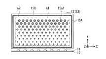
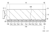
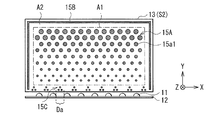
- FIG. It is a plane schematic diagram showing the structure of the light source shown in FIG. 1, and a light-guide plate (2nd surface). It is a cross-sectional schematic diagram showing the structure of the light source, the light-guide plate, and reflection sheet which were shown in FIG. It is a schematic diagram showing the other example of the surface shape of the 2nd convex part shown in FIG. It is a schematic diagram showing the other example of the surface shape of the 2nd convex part shown in FIG. It is a schematic diagram showing the other example of the surface shape of the 2nd convex part shown in FIG. It is a schematic diagram showing the other example of the surface shape of the 2nd convex part shown in FIG.
- FIG. 11 is a schematic plan view illustrating another configuration of the light guide plate illustrated in FIG. 10.
- FIG. 11 is a schematic plan view illustrating another configuration of the light guide plate illustrated in FIG. 10.
- It is a plane schematic diagram showing the structure of the light-guide plate (2nd surface) which concerns on the modification 2 with a light source.
- It is a plane schematic diagram showing the other structure of the light-guide plate shown to FIG. 13A.
- 12 is a schematic diagram illustrating a configuration example of a second convex portion according to Modification 3.
- FIG. It is a schematic diagram showing the other structural example of the 2nd convex part shown to FIG. 14A.
- FIG. 2nd surface It is a plane schematic diagram showing the structure of the light-guide plate (2nd surface) which concerns on the modification 4 with a light source. It is a cross-sectional schematic diagram for demonstrating the effect
- FIG. It is a cross-sectional schematic diagram for demonstrating the effect
- FIG. 5 It is a schematic diagram for demonstrating the arrangement configuration of the convex part of the 2nd convex part group shown in FIG. It is a figure showing the external appearance of the illuminating device which concerns on the modification 5. It is a figure showing the external appearance of the other example of the illuminating device shown in FIG. It is a figure showing the external appearance of the other example of the illuminating device shown in FIG. It is a cross-sectional schematic diagram showing the structure of the light-guide plate and reflection sheet which concern on another modification. It is a cross-sectional schematic diagram showing the structure of the light-guide plate and reflection sheet which concern on another modification. It is a cross-sectional schematic diagram showing the structure of the light-guide plate and reflection sheet which concern on another modification. It is a cross-sectional schematic diagram showing the structure of the light-guide plate and reflection sheet which concern on another modification.
- First embodiment an example of a display device including an illumination device in which a linear convex portion is provided in a peripheral region of an effective region in the second surface
- Modification 1 example in which a convex portion is provided in a selective area in an area close to the light source in the peripheral area
- Modification 2 an example in which the linear protrusions in the peripheral area are arranged to increase in width as they approach the light source
- Modification 3 example in which the circular convex portions are arranged so that the diameter or arrangement density increases in the peripheral area as they approach the light source 5.
- Modification 4 (example in which convex portions having the same material and the same diameter are arranged in the effective display area and the peripheral area) 6.
- Second Embodiment (Example in which two types of convex portions having different diffusivities are arranged in the effective display area according to the distance from the light source) 7).
- Modification 5 (another example of a lighting device) 8).
- Other modified examples (other structural examples of convex portions)
- FIG. 1 illustrates a schematic configuration of a display device (display device 1) according to an embodiment of the present disclosure.
- the display device 1 is a liquid crystal display device used as a television device, for example.
- the display device 1 includes an illumination unit (backlight) 10, an optical sheet 20, and a display panel 30.
- the display panel 30, the optical sheet 20, and the illumination unit 10 are disposed, for example, in a housing (outer housing) (not shown).
- an image is displayed in the effective display area A1, and a peripheral area (frame area) A2 of the effective display area A1 is shielded by a housing or a light shielding member (not shown).
- the effective display area A1 of the present embodiment corresponds to a specific example of “first area” of the present disclosure
- the peripheral area A2 corresponds to a specific example of “second area” of the present disclosure.
- the display panel 30 is for displaying an image such as a moving image or a still image, and includes a plurality of pixels in the effective display area A1.
- a liquid crystal layer (not shown) is sealed between a TFT (Thin Film Transistor) substrate 31 and a color filter (CF) substrate 32.
- CF color filter
- a polarizing plate 33 a is bonded to the light incident side of the TFT substrate 31, and a polarizing plate 33 b is bonded to the light output side of the CF substrate 32.
- the TFT substrate 31 includes, for example, a plurality of TFT elements and wirings such as gate lines and source lines connected to these TFT elements on a glass substrate, and a pixel electrically connected to each TFT element. An electrode is formed. One end of the TFT substrate 31 is electrically connected to, for example, a drive substrate (not shown) attached to the back side of the display device 1 via a printed board or the like.
- the CF substrate 32 has, for example, a red (R), green (G), and blue (B) color filter and a counter electrode on a glass substrate.
- the liquid crystal layer includes, for example, liquid crystal that is driven in a VA (Virtical Alignment) mode, an IPS (In Plane Switching) mode, a TN (Twisted Nematic) mode, or the like.
- the optical sheet 20 is formed by laminating, for example, a diffusion sheet (diffusion plate), a brightness enhancement film (prism sheet), a reflective polarizing film, or the like over one or more layers.
- the optical sheet 20 is disposed between the display panel 30 and the illumination unit 10.
- the illumination unit 10 is, for example, a so-called edge light type backlight.
- the illumination unit 10 includes, for example, a plurality of light sources 11, an end surface S3 facing the light sources 11, a light guide plate 13 having a light emission surface (second surface S2), and a reflection sheet 14.
- FIG. 2 schematically illustrates a planar configuration example of the light guide plate 13 and the light source 11.
- FIG. 3 is a cross-sectional view illustrating a detailed configuration of the illumination unit 10.
- the illumination unit 10 corresponds to a specific example of “illumination device” of the present disclosure.
- the reflective sheet 14 corresponds to a specific example of an “optical sheet” of the present disclosure.
- the light source 11 includes, for example, a light emitting diode (LED) that emits white light.
- the light source 11 may include, for example, an LED that emits red, green, blue, or the like.
- the light source 11 is disposed to face the end face (end face S3) of the light guide plate 13.
- a plurality of light sources 11 are arranged along one long side of the light guide plate 13 having a rectangular shape (facing the end surface S3 corresponding to one long side).
- the arrangement location of the light source 11 is not limited to this.
- a plurality may be arranged along each of the two long sides (opposite each end surface S3 corresponding to the two long sides).
- a plurality may be arranged along one or two short sides.
- a plurality may be arranged along each of the four sides.
- the plurality of light sources 11 arranged to face one end surface S3 are arranged at regular intervals, for example.
- the number and arrangement pitch of the plurality of light sources 11 are appropriately set according to the luminance of each light source 11, the thickness, size, and constituent material of the light guide plate 13.
- the light source substrate 12 holds a plurality of light sources 11 arranged along the end surface S3.
- the light source substrate 12 is electrically connected to a light source driving circuit that drives turning on and off of each light source 11.
- the light source drive circuit is formed on, for example, a drive substrate attached to the back side of the display device 1.
- the light guide plate 13 causes the light incident from the end surface S3 to propagate through the interior by reflection and then exits from the first surface S1 (emits light based on the incident light from the end surface S3 from the first surface S1). .
- the surface shape (XY planar shape) of the light guide plate 13 is, for example, a rectangular shape and has four end surfaces S3. Here, as an example, it has one end surface S3 that faces the light source 11 and three end surfaces S3 that do not face the light source 11.
- the light guide plate 13 includes a transparent resin such as an acrylic resin, a polycarbonate (PC) resin, and a cycloolefin polymer (COP) resin.
- the acrylic resin examples include PMMA (polymethyl methacrylate), a mixture of PMMA and polystyrene, or polymethacrylstyrene.
- the light guide plate 13 may be made of glass.
- a plurality of convex portions are formed by printing or processing.
- a reflection sheet 14 is bonded to the second surface S2 side of the light guide plate 13 via the plurality of convex portions.
- the reflection sheet 14 prevents light incident from the light source 11 from coming off to the second surface S2 side of the light guide plate 13 and reflects light propagating through the light guide plate 13 efficiently.
- a plurality of first protrusions 15a1 are provided in the effective display area A1 in the second surface S2 of the light guide plate 13 of the illumination unit 10, and the peripheral area A2 is provided in the peripheral area A2.
- the 2nd convex part 15B is arrange
- the plurality of first protrusions 15a1 have light diffusibility.
- the light is scattered by the first convex portion 15a1 (total reflection conditions are broken) and emitted from the first surface S1.
- the surface shape (XY planar shape) on the second surface S2 of each first protrusion 15a1 is, for example, a circular shape or a polygonal shape (here, a circular shape).
- the size (diameter) or arrangement density of the surface shapes of the plurality of first protrusions 15a1 is set so that the in-plane luminance distribution of the light emitted from the second surface S2 is uniform. It changes according to the distance from the.
- the diameters of the plurality of first convex portions 15 a 1 are configured to increase as the distance from the light source 11 increases.
- the convex part has light diffusibility
- the convex part does not necessarily have light diffusibility.
- the convex portion does not have to have light diffusibility.
- Each first convex portion 15a1 is patterned on the second surface S2 of the light guide plate 13 by a printing method such as screen printing.
- the first convex portion 15a1 is formed, for example, by dispersing particles such as silica and titanium in an adhesive resin or the like.
- the light absorptivity in the emission wavelength region of the light source 11 is low, it has a sufficient adhesive force to the light guide plate 13 and the reflective sheet 14, and has a low Young's modulus ( It is desirable to select one having a high elongation property. Since the first convex portion 15A1 has adhesiveness, the second surface S2 of the light guide plate 13 and the reflective sheet 14 are bonded via the first convex portion 15a1.
- a space (air layer 150) is formed between the first convex portions 15a1.
- the second convex portion 15B has, for example, a linear shape on the second surface S2, and is arranged so as to surround the effective display region A1 (all around the effective display region A1), for example.
- the linear width of the second convex portion 15B is constant over the entire circumference.
- the width of the second convex portion 15B may be set according to the width of the frame of the display device 1 and is not particularly limited. However, it is desirable that the second convex portion 15B is as large as possible because stress applied to the first convex portion 15a1 can be reduced. On the other hand, if the width of the second convex portion 15B becomes too large, the optical characteristics may be lowered.
- the second convex portion 15B is continuously formed over the entire circumference, but may be separated at a selective portion (a portion may have a gap). For example, if the second convex portion 15B is formed over the entire circumference, it is difficult for air to escape at a high temperature or a low temperature. Therefore, it is desirable that at least one or more gaps exist.
- the surface shape of the second convex portion 15B is not limited to the shape shown in FIG.
- the second convex portion 15B may have a plurality of linear convex portions 15b1 and 15b2 arranged in parallel.
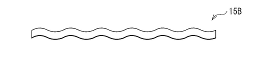
- FIG. 4A the second convex portion 15B may have a plurality of linear convex portions 15b1 and 15b2 arranged in parallel. Moreover, as shown in FIG.
- the second convex portion 15B may have a broken line shape (a plurality of convex portions 15b3 may be arranged with a gap). Or as shown to FIG. 4C, the 2nd convex part 15B may have a waveform.
- the second convex portion 15B is patterned by a printing method such as screen printing, for example, like the first convex portion 15a1.
- the 2nd convex part 15B is comprised, for example from the material which has adhesiveness.
- the constituent material of the second convex portion 15B may be the same material as the first convex portion 15a1, or may be a material different from the first convex portion 15a1. However, it is desirable for production that the second convex portion 15B is made of the same material as the first convex portion 15a1.
- the second convex portion 15B has adhesiveness, so that the second surface S2 of the light guide plate 13 and the reflective sheet 14 are bonded via the second convex portion 15B.
- the light guide plate 13 and the reflection sheet 14 are not bonded to each other over the entire surface, but at a plurality of discrete locations corresponding to the locations where the first convex portions 15a1 and the second convex portions 15B are formed. Are bonded together.
- the light emitted from the light source 11 enters the light guide plate 13 from the end surface S3.
- incident light from the end surface S3 propagates while being repeatedly reflected between the first surface S1 and the second surface S2.
- the light propagating in the light guide plate 13 enters the first convex portions 15a1 of the dot pattern 15A provided on the second surface S2, thereby being scattered (total reflection conditions are broken), and the first surface S1. It is emitted from.
- each optical member for example, an optical sheet, a light guide plate, and a light source constituting a backlight is reduced in thickness.
- the rigidity of the entire apparatus tends to be insufficient.
- the rigidity tends to be insufficient with an increase in the size of the display panel.
- each optical member of the backlight is desirably bonded to the surface (bonded to the entire surface).
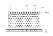
- FIG. 5 shows a planar configuration of a light guide plate and a light source according to Comparative Example 1 of the present embodiment.
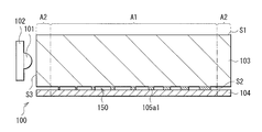
- FIG. 6 it shows about the cross-sectional structure of the illumination part 100 using this light-guide plate.
- the light source 101 held on the light source substrate 102 is disposed to face the end surface S3 corresponding to one rectangular side of the light guide plate 103.
- a plurality of convex portions 105a1 are arranged on the second surface S2 facing the first surface S1 of the light guide plate 103.
- the light guide plate 103 and the reflection sheet 104 are bonded via the plurality of convex portions 105a1.
- the convex portion 105a1 is disposed only in the effective display area A1 in the second surface S2 of the light guide plate 103.
- the plurality of convex portions 105a1 are arranged in the effective display area A1, with the surface shape size or arrangement density changing in accordance with the distance from the light source 101.
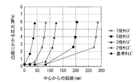
- FIG. 7 shows the relationship between the distance from the center of the light guide plate 103 and the stress applied to the convex portion.
- characteristics in each case where the size is changed to 2 times, 3 times, 5 times, and 7 times the reference size of the light guide plate 103 are also shown.
- the breaking stress mainly in the shear direction concentrates on the convex portion 105a1 which is an adhesive portion.
- the stress applied to the convex portion 105a1 increases as it approaches the outer periphery of the light guide plate 103, and the stress tends to concentrate on the outer peripheral portion.
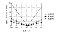
- this stress changes according to temperature.
- the second embodiment when the linear second convex portion 15B is formed over the entire circumference as shown in FIG. 2, the second embodiment has a broken line shape as shown in FIG. 4B. Each characteristic when the 2nd convex part 15B is formed is shown.
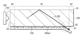
- the convex portion 105 a 1 is easily deformed or peeled off, and thus the reflective sheet 104 is peeled off (in the drawing) x1).
- the convex portion 105a1 is often formed to have a smaller diameter as it is closer to the light source 101, for example.
- the adhesion area in the vicinity of the light source 101 that is a heat source is smaller than in other regions. This also tends to cause the light guide plate 103 and the reflection sheet 104 to peel off, leading to a decrease in optical characteristics.
- the reflective sheet 14 is adhere
- a plurality of first convex portions 15a1 having light diffusibility are arranged, whereby the light propagating in the light guide plate 13 is diffused and the first surface is diffused. It is emitted from S1.
- the light guide plate 13 and the reflection sheet 14 are partially bonded to each other at the first convex portion 15a1 (the air layer 150 is interposed). Is less likely to occur, and the deterioration of optical properties is suppressed.
- the first convex portion 15a1 between the light guide plate 13 and the reflection sheet 14 is likely to be subjected to stress due to the difference in linear expansion coefficient between the light guide plate 13 and the reflection sheet 14.
- the second convex portion 15B By arranging the second convex portion 15B in at least a part of the peripheral area A2 of the second surface S2 of the light guide plate 13, the adhesion area is increased and the stress applied to the first convex portion 15a1 is reduced. Therefore, peeling between the light guide plate 13 and the reflection sheet 14 is suppressed. Thereby, the fall of the optical characteristic of the emitted light from 1st surface S1 is suppressed.
- the second convex portion 15B is disposed in at least a part of the peripheral area A2 of the effective display area A1 of the second surface S2 of the light guide plate 13, so that the light guide plate 13 and the reflective surface are reflected. Separation from the sheet 14 can be suppressed. Therefore, it becomes possible to maintain optical characteristics by suppressing separation between optical members (for example, separation between the light guide plate 13 and the reflection sheet 14).
- FIG. 10 illustrates a planar configuration of the light guide plate 13 (second surface S2) and the light source 11 according to the first modification.
- FIG. 11 is an enlarged view of a region close to the light source 11 shown in FIG.
- the configuration in which the second protrusion 15B is formed over the entire circumference of the effective display area A1 in the peripheral area A2 is illustrated.
- the second protrusion is The area close to the light source 11 in the peripheral area A2 may have a different shape and layout from other areas (areas away from the light source).
- the linear 2nd convex part 15B is arrange
- the area close to the light source 11 in the peripheral area A2 area corresponding to one side facing the light source 11 in the second surface S2
- the second convex portion 15C is disposed in the region.
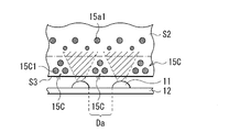
- the second convex portion 15C is disposed in a region Da between the light sources 11 in the peripheral region A2.
- the hatched portion in FIG. 11 schematically represents incident light from the light source 11.
- the second convex portion 15C includes one or a plurality of (here, three) convex portions 15c1.
- the layout of the protrusions 15c1 in the second protrusions 15C is not particularly limited, but here, the three protrusions 15c1 having a circular surface shape are arranged so as to form a triangle as a whole.
- the convex portion 15c1 is patterned by a printing method such as screen printing, for example, like the second convex portion 15B, and is made of a material having light diffusibility and adhesiveness, for example.
- the constituent material of the convex portion 15c1 may be the same material as the first convex portion 15a1 described above, or may be a material different from the first convex portion 15a1.
- it is desirable that the convex portion 15c1 is made of the same material as the first convex portion 15a1 and the second convex portion 15B. This is because the first convex portion 15a1 and the second convex portions 15B and 15C can be collectively formed by the same process, and the number of processes can be reduced as compared with the case where they are formed by separate processes.
- the second protrusions 15B and 15C are arranged in the peripheral area A2, thereby reducing the stress applied to the first protrusion 15a1 arranged in the effective display area A1 and increasing the bonding area. be able to. For this reason, peeling between the light guide plate 13 and the reflection sheet 14 (not shown in FIGS. 10 and 11) can be suppressed. Therefore, an effect equivalent to that of the first embodiment can be obtained.
- the second convex portion 15C is arranged in the selective region (for example, the region Da between the light sources 11), thereby suppressing unevenness in luminance while ensuring a bonding area. it can. As compared with the first embodiment, it is possible to further improve the optical characteristics of the light emitted from the light guide plate 13.
- region close to the light source 11 is not limited to said example.
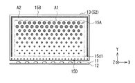
- a dot pattern 15D in which a plurality of circular second convex portions 15d1 are arranged at equal intervals may be formed.
- the second convex portion 15B is disposed only in a region away from the light source 11. Good.
- FIG. 13A illustrates a planar configuration of the light guide plate 13 (second surface S2) and the light source 11 according to Modification 2.
- the second convex portion 15B has a constant width over the entire circumference in the peripheral region A2.
- the width of the second convex portion 15B depends on the distance from the light source 11. May be different.
- the width of the linear second convex portion 15B in the peripheral region A2 increases as the distance from the light source 11 approaches (as the distance from the light source 11 decreases).
- the second convex portion 15B extends from the opposite end e2 on the light source 11 side to the end e1 on the light source 11 side in an area corresponding to the two short sides of the surface shape of the second surface S2. And has a portion (convex portion 15b4) whose width gradually increases.
- This convex part 15b4 may be arrange
- the second surface S2 is arranged continuously over a region corresponding to the three sides of the surface shape (a region excluding a region close to the light source 11).
- the 2nd convex part does not need to be arrange
- the second projecting portion 15B including the projecting portion 15b4 is disposed in the peripheral region A2, thereby reducing the stress applied to the first projecting portion 15a1 disposed in the effective display region A1, and the bonding area. Can be increased. For this reason, peeling with the light-guide plate 13 and the reflection sheet 14 (not shown in FIG. 13A) can be suppressed. Therefore, an effect equivalent to that of the first embodiment can be obtained.
- the dot pattern 15A is formed in which the diameter or arrangement density of the first protrusions 15a1 increases as the distance from the light source 11 increases.
- the adhesion area becomes small, and the reflection sheet 14 is easily peeled off.
- the convex portion 15b4 that increases in width as it approaches the light source 11 is disposed, so that it is easy to ensure a bonding area in the vicinity of the light source 11. Therefore, peeling is easier to suppress than in the first embodiment, which leads to an improvement in optical characteristics and rigidity.
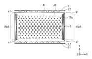
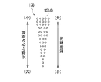
- the convex part 15b5 is arrange
- the convex portion 15b5 has a surface shape whose width increases from the central portion c toward both ends (two end portions e1) on the light source 11 side. As described above, even when the light source 11 is arranged along two sides, in the effective display area A1, the adhesion area tends to be small in the vicinity of the light source 11 as in the case where the light source 11 is arranged along the one side. . In this configuration, by arranging the convex portion 15 b 5, it becomes easy to secure a bonding area in the vicinity of the light source 11.
- the surface shape of the 2nd convex part 15B is restricted to linear form. Instead, it may have a broken line shape as shown in FIG. 4B or a wavy shape as shown in FIG. 4C.
- FIG. 14A illustrates a planar configuration of the second convex portion according to Modification 3.
- a plurality of convex portions 15b6 each having a circular shape (or polygonal shape) may be arranged as the second convex portion 15B.
- the plurality of convex portions 15b6 are arranged so that the diameter increases as the distance from the light source 11 approaches (as the distance from the light source 11 decreases).
- the plurality of convex portions 15 b 6 are arranged so that the arrangement density increases as the light source 11 is approached.
- the bonding area can be changed according to the distance from the light source 11 by changing the size or arrangement density of the surface shape of the circular convex portions 15b6 constituting the second convex portion 15B. It is possible to obtain the same effect as the second modification.
- FIG. 15 illustrates a planar configuration of the light guide plate 13 (second surface S2) and the light source 11 according to Modification 4.
- the configuration in which the size (diameter) of the surface shape of the first convex portion 15a1 is changed according to the distance from the light source 11 is illustrated.
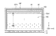
- the dot pattern 15E the diameters of the plurality of first protrusions 15e1 may be the same and the arrangement density may be different.
- the dot pattern 15E in the effective display area A1 is configured such that the arrangement density of the plurality of first protrusions 15e1 decreases as the distance from the light source 11 decreases and increases as the distance from the light source 11 increases.
- the first convex portion 15e1 is configured to include a material having light diffusibility and adhesiveness, like the first convex portion 15a1 of the first embodiment.
- the second convex portion 15F provided in the peripheral region A2 may have a surface shape such as a line as described above, but desirably, a plurality of convex portions 15f1 as in the present modification. It is comprised including.
- Each of the plurality of convex portions 15f1 is preferably made of the same material as the first convex portion 15e1 and has the same size (diameter).
- the plurality of convex portions 15f1 are arranged, for example, in at least a part of the peripheral region A2 over one or a plurality of rows (here, two rows) according to the size of the diameter. In the example shown in FIG.
- a plurality of convex portions 15f1 are densely arranged along a region corresponding to three sides of the surface shape of the second surface S2.
- the second convex portion may not be disposed, or may be disposed. In the latter case, as shown in FIG. 10, it is desirable that the second convex portion 15C be arranged in a selective region.
- the second convex portion 15F in the peripheral region A2, it is possible to increase the adhesion area while reducing the stress applied to the first convex portion 15e1 disposed in the effective display region A1. it can. For this reason, peeling with the light-guide plate 13 and the reflection sheet 14 (not shown in FIG. 13A) can be suppressed. Therefore, an effect equivalent to that of the first embodiment can be obtained.
- each convex portion 15f1 is made of the same material as the first convex portion 15e1 disposed in the effective display area A1, and has the same size. There is.
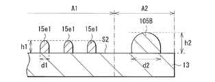
- a plurality of protrusions 15f1 are formed in the effective display area A1, and a second protrusion 105B having a different material or a different size from the first protrusion 15e1 is formed in the peripheral area A2.
- the height h1 of the first protrusion 15e1 may be different from the height h2 of the second protrusion 105B.
- the second convex portion 105B is made of the same material as the first convex portion 15e1, if the size (diameter or width d1, d2) is different (d1 ⁇ d2), the second convex portion 105B Is higher than the height h1 of the first convex portion 15e1 (h1 ⁇ h2). As a result, the adhesion between the light guide plate 13 and the reflection sheet 14 is locally reduced, and the optical characteristics are impaired.
- the convex portion 15f1 arranged in the peripheral area A2 is made of the same material and has the same size as the first convex portion 15e1 arranged in the effective display area A1.
- the height of the convex portion 15f1 is equal to the height h1 of the first convex portion 15e1. For this reason, the adhesiveness of the light-guide plate 13 and the reflective sheet 14 improves, and the fall of an optical characteristic can be suppressed.
- FIG. 18 illustrates a planar configuration (configuration of the second surface S2) and a configuration of the light source 11 of the light guide plate (light guide plate 13A) according to the second embodiment of the present disclosure.
- the light guide plate 13A according to the present embodiment constitutes the illumination unit 10 in a state of being bonded (integrated) with the reflection sheet 14 in the same manner as the light guide plate 13 according to the first embodiment, and the display device. 1 is used. Further, the light source 11 is disposed to face the end surface S3 of the light guide plate 13A.
- the light guide plate 13A has a rectangular surface shape on the second surface S2, and the same material as the light guide plate 13 of the first embodiment can be used as a constituent material.
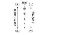
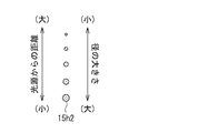
- a plurality of types of convex portions (here, two types of convex portions 15h1 and 15h2) having different diffusivities are arranged in the effective display area A1 of the second surface S2.
- the convex portion 15h1 (third convex portion) is made of a material having a higher diffusivity
- the convex portion 15h2 (fourth convex portion) is made of a material having a smaller diffusivity.
- the diffusivity of the convex part 15h1 is larger than the diffusivity of the convex part 15h2.
- the same materials as those described as the constituent material of the first convex portion 15a1 of the first embodiment can be used.
- a plurality of convex portions 15h1 are provided in the effective display area A1.
- the surface shape size or arrangement density of the convex portions 15h1 increases as the distance from the light source 11 increases (as the distance from the light source 11 increases).
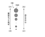
- the surface shape of the convex portion 15 h 1 is a circular shape, and its diameter increases as the distance from the light source 11 increases.
- a plurality of convex portions 15h2 are provided in the effective display area A1.
- the size or arrangement density of the surface shape of the convex portions 15h2 decreases as the distance from the light source 11 increases (as the distance from the light source 11 increases).
- the surface shape of the convex portion 15 h 2 is circular, and the diameter thereof becomes smaller as the distance from the light source 11 increases.
- the diffusivity of these convex portions 15h1, 15h2 can be adjusted, for example, by changing the size and concentration of particles of silica and titanium contained in the convex portions 15h1, 15h2.
- the reflective sheet 14 (not shown in FIG. 18) is bonded to the second surface S2 side of the light guide plate 13A via the plurality of convex portions 15h1 and 15h2 having light diffusibility.
- the light propagating through the light guide plate 13A is diffused by the plurality of convex portions 15h1 and 15h2, and emitted from the first surface S1 (not shown in FIG. 18) of the light guide plate 13A.
- the diffusivity of the convex part 15h1 is larger than the diffusivity of the convex part 15h2.
- the size or arrangement density of the surface shape decreases as the distance from the light source 11 increases.
- the size of the surface shape or the arrangement density increases as the distance from the light source 11 increases.
- the adhesion area can be increased while maintaining the tendency to increase the diffusibility as the distance from the light source 11 increases. Therefore, an adhesion area can be secured while maintaining the luminance distribution of the emitted light from the first surface S1 of the light guide plate 13A. Therefore, an effect equivalent to that of the first embodiment can be obtained.
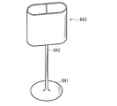
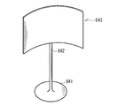
- ⁇ Modification 5> 20 and 21 show the appearance of a tabletop lighting device to which the lighting unit 10 of the first embodiment or the like is applied.
- the illuminating unit 10 can be applied to an illuminating device such as this modified example in addition to the display device 1 described above.
- the illumination device is a column in which a lighting unit 843 is attached to a support column 842 provided on a base 841.
- the lighting unit 843 includes the lighting unit 10 according to the first embodiment. Yes.
- the illumination unit 843 can have an arbitrary shape such as a cylindrical shape shown in FIG. 20 or a curved shape shown in FIG. 21 by making the light guide plate 13 and the reflection sheet 14 into a curved shape.
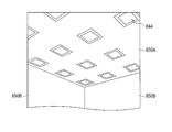
- FIG. 22 shows the appearance of an indoor lighting device to which the lighting unit 10 according to the first embodiment or the like is applied.
- the illuminating unit 10 can be applied to an illuminating device such as this modified example in addition to the display device 1 described above.
- This illuminating device has the illumination part 844 comprised by the illumination part 10 which concerns on the said 1st Embodiment, for example.
- the illumination units 844 are arranged at an appropriate number and interval on the ceiling 850A of the building. Note that the lighting unit 844 can be installed not only in the ceiling 850A but also in an arbitrary place such as a wall 850B or a floor (not shown) depending on the application.
- the present disclosure is not limited to the above-described embodiments and the like, and various modifications are possible.
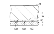
- the configuration in which the light guide plate 13 and the reflection sheet 14 are bonded via the adhesive convex portions is exemplified.
- the convex part does not necessarily have adhesiveness.
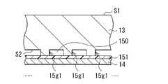
- a plurality of convex portions 15g1 may be formed by processing the second surface S2 side of the light guide plate 13 with, for example, a laser. That is, the convex portion 15g1 may be a part of the light guide plate 13.
- a thin adhesive layer 151 is formed on the surface of the reflective sheet 14 on the light guide plate 13 side, and the light guide plate 13 and the reflective sheet 14 are adhered by the adhesive layer 151, but the region between the convex portions 15g1 is The air layer 150 is formed, and a decrease in optical characteristics can be suppressed as in the above embodiment.
- the shape on the second surface S2 side of the light guide plate 13 can take various shapes by processing.
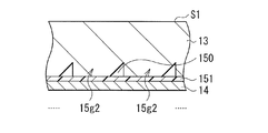
- a convex portion 15g2 having a trapezoidal cross section may be formed.
- the region between the convex portions 15g2 (the concave portion having a triangular cross section) becomes the air layer 150.
- liquid crystal display device was illustrated as the display apparatus 1, you may apply to a plasma display apparatus and an organic electroluminescent display apparatus.
- each member described in the above embodiment is an example, and it is not necessary to provide all the members, and other members may be further provided.
- the present disclosure can take the following configurations.
- a light guide plate having, An optical sheet bonded to the second surface side of the light guide plate via the plurality of convex portions;
- the plurality of convex portions are A plurality of first protrusions disposed in a first region in the second surface;
- An illumination device comprising: one or a plurality of second convex portions arranged in at least a part of a second region around the first region in the second surface.
- the lighting device according to (1) wherein the size or arrangement density of the surface shape of the one or more second protrusions on the second surface is different depending on the distance from the light source.
- the surface shape of the one or more second convex portions has a linear shape, a broken line shape, or a wave shape in at least a part of the second region of the light guide plate, The width
- a plurality of the second convex portions are provided, Each surface shape on the second surface of the plurality of second convex portions has a circular shape or a polygonal shape,
- the illuminating device according to (2) wherein a diameter or an arrangement density in each surface shape of the plurality of second convex portions increases as the light source approaches.
- a plurality of the second convex portions are provided, Of the plurality of second convex portions, the second convex portion disposed in a region away from the light source is disposed so as to surround the first region, Of the plurality of second convex portions, the second convex portion disposed in a region close to the light source is disposed in a selective region corresponding to the position of the light source.
- the lighting device according to any one of 5).
- a plurality of the second convex portions are provided, Each surface shape on the second surface of the first and second convex portions has a circular shape or a polygonal shape,
- the plurality of first protrusions have a plurality of third and fourth protrusions having different diffusivities, respectively.
- the diffusivity of the third convex part is larger than the diffusivity of the fourth convex part,
- the size or arrangement density of the surface shape on the second surface of the plurality of third protrusions increases as the distance from the light source increases.
- the illumination device according to any one of (1) to (8), wherein a size or arrangement density of a surface shape of the plurality of fourth convex portions on the second surface decreases with distance from the light source. . (10) Each surface shape in the said 2nd surface of a said 3rd and 4th convex part has circular shape or polygonal shape.
- the illuminating device as described in said (9).
- the lighting device according to any one of (1) to (10), wherein the first and second protrusions include an adhesive material that bonds the light guide plate and the optical sheet.
- an adhesive layer is provided between the first and second convex portions and the optical sheet.
- An end face disposed to face the plurality of light sources, a first face that emits light based on incident light from the end face, and a second face that faces the first face and includes a plurality of convex portions.
- a light guide plate having, An optical sheet bonded to the second surface side of the light guide plate via the plurality of convex portions;
- the plurality of convex portions have a plurality of third and fourth convex portions each having a different diffusivity,
- the diffusivity of the third convex part is larger than the diffusivity of the fourth convex part,
- the size or arrangement density of the surface shape on the second surface of the plurality of third protrusions increases as the distance from the light source increases.
- the illuminating device in which the size or arrangement density of the surface shape of the plurality of fourth convex portions on the second surface decreases as the distance from the light source increases.
- the lighting device includes: Multiple light sources; An end face disposed to face the plurality of light sources, a first face that emits light based on incident light from the end face, and a second face that faces the first face and includes a plurality of convex portions.
- a light guide plate having, An optical sheet bonded to the second surface side of the light guide plate via the plurality of convex portions;
- the plurality of convex portions are A plurality of first protrusions disposed in a first region in the second surface;
- a display device comprising: one or a plurality of second convex portions arranged in at least a part of a second region which is a peripheral region of the first region in the second surface.
- the lighting device includes: Multiple light sources; An end face disposed to face the plurality of light sources, a first face that emits light based on incident light from the end face, and a second face that faces the first face and includes a plurality of convex portions.
- a light guide plate having, An optical sheet bonded to the second surface side of the light guide plate via the plurality of convex portions;
- the plurality of convex portions have a plurality of third and fourth convex portions each having a different diffusivity,
- the diffusivity of the third convex part is larger than the diffusivity of the fourth convex part,
- the size or arrangement density of the surface shape on the second surface of the plurality of third protrusions increases as the distance from the light source increases.
- a display device in which the size or arrangement density of a plurality of the fourth convex portions on the second surface decreases as the distance from the light source increases.
Landscapes
- Physics & Mathematics (AREA)
- General Physics & Mathematics (AREA)
- Optics & Photonics (AREA)
- Engineering & Computer Science (AREA)
- Crystallography & Structural Chemistry (AREA)
- Chemical & Material Sciences (AREA)
- Nonlinear Science (AREA)
- General Engineering & Computer Science (AREA)
- Computer Hardware Design (AREA)
- Theoretical Computer Science (AREA)
- Mathematical Physics (AREA)
- Planar Illumination Modules (AREA)
- Liquid Crystal (AREA)
Abstract
この照明装置は、複数の光源と、複数の光源に対向して配置された端面と、端面からの入射光に基づく光を出射する第1面と、第1面に対向すると共に複数の凸部を含む第2面とを有する導光板と、導光板の第2面の側に、複数の凸部を介して接着された光学シートとを備える。複数の凸部は、第2面内の第1領域に配置された複数の第1の凸部と、第2面内の第1領域の周辺の第2領域の少なくとも一部に配置された1または複数の第2の凸部とを有する。
Description
本開示は、照明装置と、この照明装置を用いた表示装置に関する。
液晶表示装置などの表示装置では、装置全体の薄型化を実現するために、表示パネルあるいはバックライトを構成する光学部材(例えば光学シート、導光板および光源など)のそれぞれにおいて薄型化が図られている。ところが、この薄型化によって、装置全体の剛性を維持することが困難となる。特に、表示パネルの大型化に伴って剛性が不十分となり易い。このことから、例えばバックライトの各光学部材が積層される際に、これらを互いに面接着させる(面全体を接着させる)ことが望ましい。
一方で、面接着させた場合には、輝度(発光輝度または表示輝度)などの光学特性を維持しにくい。光学特性を十分に発揮させるために、各光学部材間に低屈折層(空気層など)を介在させることが望まれる。そこで、各光学部材が、点状あるいは線状の部分的な領域において接着された面光源装置が提案されている(例えば特許文献1)。
しかしながら、上記特許文献1の手法では、各光学部材同士が剥離し易く、光学特性を維持することが困難である。
光学部材同士の剥離を抑制して光学特性を維持することが可能な照明装置および表示装置を提供することが望ましい。
本開示の一実施の形態の第1の照明装置は、複数の光源と、複数の光源に対向して配置された端面と、端面からの入射光に基づく光を出射する第1面と、第1面に対向すると共に複数の凸部を含む第2面とを有する導光板と、導光板の第2面の側に、複数の凸部を介して接着された光学シートとを備えたものである。複数の凸部は、第2面内の第1領域に配置された複数の第1の凸部と、第2面内の第1領域の周辺の第2領域の少なくとも一部に配置された1または複数の第2の凸部とを有する。
本開示の一実施の形態の第1の表示装置は、表示パネルと、表示パネルを照明する上記本開示の一実施の形態の第1の照明装置とを備えたものである。
本開示の一実施の形態の第1の照明装置および表示装置では、導光板の第2面の側に、複数の凸部を介して光学シートが接着されている。また、複数の凸部として、第2面の第1領域に配置された第1の凸部により、導光板内を伝播する光が反射されて第1面から出射される。ここで、導光板と光学シートとは一般に線膨張係数が異なり、この線膨張係数の差に起因して、導光板と光学シートとの間に介在する第1の凸部には応力がかかり易い。導光板の第2面の第1領域の周辺の第2領域の少なくとも一部に第2の凸部が配置されることで、接着面積が増大すると共に、第1の凸部にかかる応力が低減される。
本開示の一実施の形態の第2の照明装置は、複数の光源と、複数の光源に対向して配置された端面と、端面からの入射光に基づく光を出射する第1面と、第1面に対向すると共に複数の凸部を含む第2面とを有する導光板と、導光板の第2面の側に、複数の凸部を介して接着された光学シートとを備えたものである。複数の凸部は、互いに異なる拡散度を有する第3および第4の凸部をそれぞれ複数有し、第3の凸部の拡散度は第4の凸部の拡散度よりも大きく、複数の第3の凸部の前記第2面における面形状の大きさまたは配置密度が光源から離れるに従って大きくなり、複数の第4の凸部の第2面における面形状の大きさまたは配置密度が光源から離れるに従って小さくなっている。
本開示の一実施の形態の第2の表示装置は、表示パネルと、表示パネルを照明する上記本開示の一実施の形態の第2の照明装置とを備えたものである。
本開示の一実施の形態の第2の照明装置および表示装置では、導光板の第2面の側に、複数の凸部を介して光学シートが接着されている。複数の凸部により、導光板内を伝播する光が反射されて第1面から出射される。これら複数の凸部は、互いに異なる拡散度を有する第3および第4の凸部をそれぞれ複数有し、第3の凸部の拡散度が、第4の凸部の拡散度よりも大きい。複数の第3の凸部の面形状の大きさまたは配置密度が光源から離れるに従って大きくなり、複数の第4の凸部の面形状の大きさまたは配置密度が光源から離れるに従って小さくなる。これにより、第1面からの出射光の輝度分布を維持しつつ、凸部による接着面積が確保される。
本開示の一実施の形態の第1の照明装置および表示装置によれば、導光板の第2面に複数の凸部が設けられ、これらの複数の凸部を介して導光板と光学シートとが接着されている。また、複数の凸部として、第1領域には第1の凸部が配置されている。これにより、第1面からの出射光の光学特性の低下を抑制することができる。また、導光板の第2面において、第1領域の周辺の第2領域の少なくとも一部に第2の凸部が配置されることで、接着面積を増大すると共に第1の凸部にかかる応力を低減することができる。従って、導光板と光学シートとの剥離を抑制することができる。よって、光学部材同士の剥離を抑制して光学特性を維持することが可能となる。
本開示の一実施の形態の第2の照明装置および表示装置によれば、導光板の第2面に、複数の凸部が設けられ、これらの複数の凸部を介して導光板と光学シートとが接着されている。また、複数の凸部が、互いに異なる拡散度を有する第3および第4の凸部をそれぞれ複数有し、第3の凸部の拡散度が、第4の凸部の拡散度よりも大きい。複数の第3の凸部では、その面形状または配置密度が光源から離れるに従って大きくなり、複数の第4の凸部では、その面形状または配置密度が光源から離れるに従って小さくなることにより、輝度分布を維持しつつ、接着面積を確保することができる。よって、光学部材同士の剥離を抑制して光学特性を維持することが可能となる。
尚、上記内容は本開示の一例である。本開示の効果は、上述したものに限らず、他の異なる効果であってもよいし、更に他の効果を含んでいてもよい。
本開示の実施の形態について図面を参照して以下の順に詳細に説明する。
1.第1の実施の形態(第2面内の有効領域の周辺領域に線状の凸部を設けた照明装置を備えた表示装置の例)
2.変形例1(周辺領域のうち光源に近接する領域では選択的な領域に凸部を設けた例)
3.変形例2(周辺領域において線状の凸部が光源に近づくに従って幅が大きくなるように配置された例)
4.変形例3(周辺領域において円形状の凸部が光源に近づくに従って径または配置密度が大きくなるように配置された例)
5.変形例4(有効表示領域と周辺領域とで同一材料および同一径の凸部を配置した例)6.第2の実施の形態(有効表示領域において拡散度の異なる2種類の凸部を光源からの距離に応じて配置した例)
7.変形例5(照明装置の他の例)
8.他の変形例(凸部の他の構成例)
1.第1の実施の形態(第2面内の有効領域の周辺領域に線状の凸部を設けた照明装置を備えた表示装置の例)
2.変形例1(周辺領域のうち光源に近接する領域では選択的な領域に凸部を設けた例)
3.変形例2(周辺領域において線状の凸部が光源に近づくに従って幅が大きくなるように配置された例)
4.変形例3(周辺領域において円形状の凸部が光源に近づくに従って径または配置密度が大きくなるように配置された例)
5.変形例4(有効表示領域と周辺領域とで同一材料および同一径の凸部を配置した例)6.第2の実施の形態(有効表示領域において拡散度の異なる2種類の凸部を光源からの距離に応じて配置した例)
7.変形例5(照明装置の他の例)
8.他の変形例(凸部の他の構成例)
<第1の実施の形態>
[構成]
図1は、本開示の一実施の形態に係る表示装置(表示装置1)の概略構成を表したものである。この表示装置1は例えばテレビジョン装置として用いられる液晶表示装置である。
[構成]
図1は、本開示の一実施の形態に係る表示装置(表示装置1)の概略構成を表したものである。この表示装置1は例えばテレビジョン装置として用いられる液晶表示装置である。
表示装置1は、照明部(バックライト)10と、光学シート20と、表示パネル30とを備える。これらの表示パネル30、光学シート20および照明部10は、例えば図示しない筐体(外筐)内に配置されている。
この表示装置1では、有効表示領域A1において画像が表示されると共に、この有効表示領域A1の周辺領域(額縁領域)A2は、図示しない筐体や遮光部材によって遮光されている。尚、本実施の形態の有効表示領域A1が本開示の「第1領域」の一具体例、周辺領域A2が、本開示の「第2領域」の一具体例にそれぞれ相当する。
表示パネル30は、動画像または静止画像等の画像を表示するためのものであり、有効表示領域A1内に複数の画素を含んでいる。この表示パネル30は、例えば、TFT(Thin Film Transistor)基板31とカラーフィルタ(CF)基板32との間に液晶層(図示せず)が封止されたものである。表示パネル30は、TFT基板31の光入射側には偏光板33aが、CF基板32の光出射側には偏光板33bが、それぞれ貼り合わせられている。
TFT基板31は、例えばガラス基板上に、複数のTFT素子と、これらのTFT素子に接続されるゲート線およびソース線等の配線とが設けられると共に、各TFT素子に電気的に接続された画素電極が形成されたものである。このTFT基板31の一端は、例えば表示装置1の背面側に取り付けられた駆動基板(図示せず)に、プリント基板等を介して電気的に接続されている。CF基板32は、例えばガラス基板上に、赤(R),緑(G),青(B)のカラーフィルタと対向電極とを有するものである。液晶層は、例えばVA(Virtical Alignment)モード、IPS(In Plane Switching)モードまたはTN(Twisted Nematic)モード等により駆動される液晶を含んでいる。
光学シート20は、例えば拡散シート(拡散板)、輝度上昇フィルム(プリズムシート)および反射型偏光フィルム等を1または複数層にわたって積層したものである。光学シート20は、ここでは、表示パネル30と照明部10との間に配置されている。
照明部10は、例えばいわゆるエッジライト方式のバックライトである。この照明部10は、例えば、複数の光源11と、この光源11に対向する端面S3と、光出射面(第2面S2)を有する導光板13と、反射シート14とを備える。図2は、導光板13と光源11との平面構成例を模式的に表したものである。図3は、照明部10の詳細構成を表す断面図である。この照明部10が、本開示の「照明装置」の一具体例に相当する。また、反射シート14が、本開示の「光学シート」の一具体例に相当する。
光源11は、例えば白色光を発するLED(Light Emitting Diode;発光ダイオード)を含んで構成されている。あるいは、光源11は、例えば赤色,緑色または青色等を発するLEDを含んでいてもよい。光源11は、例えば、導光板13の端面(端面S3)に対向して配置されている。ここでは、光源11は、矩形状の導光板13の1つの長辺に沿って(1つの長辺に対応する端面S3に対向して)複数配置されている。但し、光源11の配置箇所はこれに限定されるものではない。例えば、2つの各長辺に沿って(2つの長辺に対応する各端面S3に対向して)複数配置されていてもよい。また、1または2つの各短辺に沿って複数配置されていてもよい。あるいは、4つの辺のそれぞれに沿って複数配置されていてもよい。
1つの端面S3に対向配置される複数の光源11は、例えば等間隔で配置されている。これらの複数の光源11の個数および配列ピッチは、個々の光源11の輝度、導光板13の厚み、サイズおよび構成材料等に応じて適宜設定される。
光源基板12は、端面S3に沿って配列する複数の光源11を保持するものである。この光源基板12は、各光源11の点灯および消灯を駆動する光源駆動回路に電気的に接続されている。光源駆動回路は、例えば表示装置1の背面側に取り付けられた駆動基板上に形成されている。
導光板13は、端面S3から入射した光を、反射により内部を伝播させた後に第1面S1から出射させる(端面S3からの入射光に基づく光を第1面S1から出射させる)ものである。この導光板13の面形状(XY平面形状)は例えば矩形状であり、4つの端面S3を有している。ここでは、一例として、光源11に対向する1つの端面S3と、光源11に非対向の3つの端面S3とを有している。この導光板13は、例えばアクリル樹脂、ポリカーボネート(PC)樹脂およびシクロオレフィンポリマー(COP)樹脂などの透明樹脂を含んで構成されている。アクリル樹脂としては、例えばPMMA(ポリメチルメタクリレート)、PMMAとポリスチレンとの混合物またはポリメタクリルスチレン等が挙げられる。あるいは、導光板13は、ガラスにより構成されていてもよい。導光板13の第1面S1に対向する面(第2面S2)には、複数の凸部(後述の第1凸部15a1,第2凸部15B)が印刷または加工により形成されている。この導光板13の第2面S2の側には、これらの複数の凸部を介して反射シート14が接着されている。
反射シート14は、光源11から入射された光の導光板13の第2面S2側への抜けを防ぐと共に、導光板13の内部を伝播する光を効率よく、反射させるものである。
本実施の形態では、図2に示したように、この照明部10の導光板13の第2面S2内の有効表示領域A1には複数の第1凸部15a1が、周辺領域A2には、第2凸部15Bが、それぞれ配置されている。
複数の第1凸部15a1(ドットパターン15A)は、光拡散性を有している。導光板13内を反射により伝播する光が、第1凸部15a1へ入射すると、この第1凸部15a1において散乱され(全反射条件を崩され)、第1面S1から出射されるようになっている。各第1凸部15a1の第2面S2における面形状(XY平面形状)は、例えば円形状または多角形状(ここでは円形状)である。ドットパターン15Aでは、第2面S2からの出射光の面内輝度分布が均一となるように、例えば、複数の第1凸部15a1の面形状の大きさ(径)または配置密度が、光源11からの距離に応じて変化している。図2の例では、複数の第1凸部15a1の径が光源11から離れるに従って大きくなるように構成されている。尚、ここでは、凸部が光拡散性を有するが、凸部は必ずしも光拡散性を有する必要はない。例えば、反射シート14が拡散性を有する場合には、凸部は光拡散性を有していなくともよい。
各第1凸部15a1は、導光板13の第2面S2に、例えばスクリーン印刷などの印刷法によりパターン形成されている。第1凸部15a1は、例えば接着性を有する樹脂などに例えばシリカおよびチタン等の粒子を分散させて形成されたものである。接着性を有する材料としては、光学特性の観点から、光源11の発光波長域における吸収率が低く、導光板13および反射シート14に対して十分な接着力を持ち、かつ低ヤング率を有する(伸び性が高い)ものが選択されることが望ましい。第1凸部15A1が接着性を有することで、この第1凸部15a1を介して、導光板13の第2面S2と反射シート14とが接着されている。各第1凸部15a1同士の間は空隙(空気層150)となっている。
第2凸部15Bは、第2面S2における面形状が例えば線状を有し、例えば有効表示領域A1を囲むように(有効表示領域A1の全周に)配置されている。第2凸部15Bの線状の幅は、ここでは全周にわたって一定となっている。第2凸部15Bの幅は、表示装置1の額縁の幅に応じて設定されればよく、特に限定されないが、できるだけ大きい方が第1凸部15a1へかかる応力をより低減できるため望ましい。一方で、第2凸部15Bの幅が大きくなり過ぎると、光学特性が低下することがあるので、それらの応力低減の効果と光学特性との兼ね合いから適切な幅が設定されるとよい。第2凸部15Bは、ここでは、全周にわたって連続して形成されているが、選択的な一部において離間していてもよい(一部に間隙を有していてもよい)。例えば、全周にわたって第2凸部15Bが形成されると高温時または低温時において空気が抜けにくくなるがあるため、少なくとも1箇所以上は、間隙が存在することが望ましい。また、第2凸部15Bの面形状としては、図2に示した形状に限定されない。例えば、図4Aに示したように、第2凸部15Bが、並行して配置された複数本の線状の凸部15b1,15b2を有していてもよい。また、図4Bに示したように、第2凸部15Bが破線状を有していてもよい(複数の凸部15b3が間隙を介して配置されていてもよい)。あるいは、図4Cに示したように、第2凸部15Bが波状を有していてもよい。
この第2凸部15Bは、第1凸部15a1と同様、例えばスクリーン印刷などの印刷法によりパターン形成されている。第2凸部15Bは、例えば接着性を有する材料から構成されている。第2凸部15Bの構成材料は、第1凸部15a1と同一の材料であってもよいし、第1凸部15a1と異なる材料であってもよい。但し、第2凸部15Bは、第1凸部15a1と同一の材料により構成されていることが、生産上、望ましい。
第1凸部15a1と同様、第2凸部15Bが接着性を有することで、この第2凸部15Bを介して、導光板13の第2面S2と反射シート14とが接着されている。このように、導光板13と反射シート14とは面全体で接着されるのではなく、第1凸部15a1および第2凸部15Bの形成箇所に対応する、離散的な複数の箇所において、部分的に接着されている。
[作用、効果]
表示装置1では、TFT基板31およびCF基板32との間に駆動電圧が印加されることで、表示パネル30における液晶の光学特性が画素毎に変化する。照明部10から出射された光が、光学シート20を介して表示パネル30を透過することにより、表示パネル30上に映像が表示される。
表示装置1では、TFT基板31およびCF基板32との間に駆動電圧が印加されることで、表示パネル30における液晶の光学特性が画素毎に変化する。照明部10から出射された光が、光学シート20を介して表示パネル30を透過することにより、表示パネル30上に映像が表示される。
このとき、照明部10では、光源11が駆動されると、この光源11から発せられた光は、端面S3から導光板13内へ入射する。導光板13の内部では、端面S3からの入射光が、第1面S1と第2面S2との間で反射を繰り返しながら伝播する。この導光板13内を伝播する光が、第2面S2に設けられたドットパターン15Aの各第1凸部15a1に入射することで、散乱され(全反射条件が崩され)、第1面S1から出射される。
ここで、一般的な表示装置では、薄型化を実現するために、例えばバックライトを構成する各光学部材(例えば光学シート、導光板および光源など)の薄型化が図られている。ところが、この薄型化された各光学部材を積層する、あるいは外周部だけを接着する、という手法では、装置全体の剛性が不十分となり易い。特に、表示パネルの大型化に伴って剛性が不十分となり易い。このため、剛性を維持するためには、例えばバックライトの各光学部材が、面接着される(面全体で接着される)ことが望ましい。
ところが、面接着させた場合には、輝度(発光輝度または表示輝度)などの光学特性を維持しにくい。光学特性を十分に発揮させるために、各光学部材間に低屈折層(空気層など)を設けることが望まれる。
例えば、図5に、本実施の形態の比較例1に係る導光板と光源との平面構成について示す。図6には、この導光板を用いた照明部100の断面構成について示す。この比較例1では、上記実施の形態と同様、光源基板102に保持された光源101が、導光板103の矩形状の1辺に対応する端面S3に対向して配置されている。また、導光板103の第1面S1に対向する第2面S2に、複数の凸部105a1が配置されている。更に、これらの複数の凸部105a1を介して、導光板103と反射シート104とが接着されている。即ち、凸部105a1の配置箇所に対応して部分接着されている。これにより、導光板103と反射シート104との間に空気層150が形成され、上記の面接着の場合よりも光学特性を維持し易くなる。但し、比較例では、導光板103の第2面S2内の有効表示領域A1にのみ、凸部105a1が配置されている。これらの複数の凸部105a1は、有効表示領域A1において、光源101からの距離に応じて、面形状の大きさまたは配置密度が変化して配置されている。
ここで、図7に、導光板103における中心からの距離と凸部に係る応力との関係について示す。また、導光板103の基準サイズに対して、2倍、3倍、5倍、7倍とサイズが変化した各場合の特性についても示す。高温時または低温時には、導光板103と反射シート104との材質の線膨張係数差に起因して、せん断方向を主とする破壊応力が接着部である凸部105a1に集中する。この凸部105a1にかかる応力は、導光板103の外周に近づくほど大きくなり、外周部に応力が集中する傾向にある。また、図8に示したように、この応力は、温度に応じて変化する。尚、図8に示した実施例1は、図2に示したような全周にわたって線状の第2凸部15Bを形成した場合、実施例2は、図4Bに示したような破線状の第2凸部15Bを形成した場合のそれぞれの特性を示している。
この結果、図9に模式的に示したように、例えば導光板103の外周部では、凸部105a1が変形したり、剥がれたりし易く、これにより反射シート104が剥離してしまう(図中のx1)。導光板103内を伝播してきた光L100が、この剥離部分に入射すると、例えば第2面S2から光抜け等が生じ、光学特性が低下する。加えて、凸部105a1は、例えば光源101に近いほど径が小さく形成されていることが多い。この場合、熱源である光源101の付近での接着面積が他の領域に比べて小さくなる。このことによっても導光板103と反射シート104との剥離が生じ易く、光学特性の低下につながる。
これに対し、本実施の形態では、導光板13の第2面S2の側に、複数の凸部(第1凸部15a1,第2凸部15B)を介して反射シート14が接着されている。具体的には、第2面S2の有効表示領域A1には光拡散性を有する複数の第1凸部15a1が配置され、これにより、導光板13内を伝播する光が拡散されて第1面S1から出射される。このように、導光板13と反射シートと14が、第1凸部15a1において部分的に接着される(空気層150が介在する)ことから、面接着される場合に比べ、界面での光損失が生じにくくなり、光学特性の低下が抑制される。
ここで、上述したように導光板13と反射シート14との間の第1凸部15a1には、導光板13と反射シート14との線膨張係数差に起因する応力がかかり易い。導光板13の第2面S2の周辺領域A2の少なくとも一部に、第2凸部15Bが配置されることで、接着面積が増大すると共に、第1凸部15a1にかかる応力が低減される。従って、導光板13と反射シート14との剥離が抑制される。これにより、第1面S1からの出射光の光学特性の低下が抑制される。
以上のように本実施の形態では、導光板13の第2面S2の有効表示領域A1の周辺領域A2の少なくとも一部に、第2凸部15Bが配置されることで、導光板13と反射シート14との剥離を抑制することができる。よって、光学部材同士の剥離(例えば、導光板13と反射シート14との剥離)を抑制して光学特性を維持することが可能となる。
次に、上記第1の実施の形態の変形例および他の実施の形態について説明する。以下では、上記第1の実施の形態と同様の構成要素については同一の符号を付し、適宜その説明を省略する。
<変形例1>
図10は、変形例1に係る導光板13(第2面S2)と光源11との平面構成を表したものである。図11は、図10に示した光源11に近接する領域を拡大したものである。上記第1の実施の形態では、周辺領域A2において、第2凸部15Bが有効表示領域A1の全周にわたって形成された構成を例示したが、本変形例のように、第2凸部は、周辺領域A2のうち光源11に近接する領域では、他の領域(光源から離れた領域)と異なる形状、レイアウトを有していてもよい。
図10は、変形例1に係る導光板13(第2面S2)と光源11との平面構成を表したものである。図11は、図10に示した光源11に近接する領域を拡大したものである。上記第1の実施の形態では、周辺領域A2において、第2凸部15Bが有効表示領域A1の全周にわたって形成された構成を例示したが、本変形例のように、第2凸部は、周辺領域A2のうち光源11に近接する領域では、他の領域(光源から離れた領域)と異なる形状、レイアウトを有していてもよい。
例えば、周辺領域A2のうちの光源11から離れた領域(第2面S2のうちの光源11に非対向となる3つの辺に対応する領域)では、上記第1の実施の形態と同様に、線状の第2凸部15Bが有効表示領域A1を囲むように配置されている。一方、周辺領域A2のうちの光源11に近接する領域(第2面S2のうちの光源11に対向する1つの辺に対応する領域)では、上記第1の実施の形態と異なり、選択的な領域に第2凸部15Cが配置されている。
第2凸部15Cは、周辺領域A2のうちの光源11同士の間の領域Daに配置されていることが望ましい。尚、図11の斜線部分は、光源11からの入射光を模式的に表している。この第2凸部15Cは、1または複数(ここでは3つ)の凸部15c1を含んで構成されている。第2凸部15Cにおける凸部15c1のレイアウトは特に限定されるものではないが、ここでは、円形状の面形状を有する3つの凸部15c1が全体として三角形を成すように配置されている。
この凸部15c1は、第2凸部15Bと同様、例えばスクリーン印刷などの印刷法によりパターン形成され、例えば光拡散性および接着性を有する材料から構成されている。凸部15c1の構成材料は、上述した第1凸部15a1と同一の材料であってもよいし、第1凸部15a1と異なる材料であってもよい。但し、凸部15c1は、第1凸部15a1および第2凸部15Bと同一の材料により構成されていることが望ましい。第1凸部15a1および第2凸部15B,15Cを同一の工程により一括して形成することができ、別々の工程で形成する場合に比べ工程数を削減できるためである。
本変形例では、周辺領域A2に、第2凸部15B,15Cが配置されることで、有効表示領域A1に配置された第1凸部15a1へかかる応力を低減しつつ、接着面積を増大させることができる。このため、導光板13と反射シート14(図10および図11には図示せず)との剥離を抑制することができる。従って、上記第1の実施の形態と同等の効果を得ることができる。
また、周辺領域A2のうちの光源11に近接する領域では、光源11の輝度および配列ピッチ等に起因して輝度むらが生じ易い。本変形例のように、その選択的な領域(例えば光源11同士の間の領域Da)に第2凸部15Cが配置されることで、接着面積を確保しつつ、輝度むらを抑制することができる。上記第1の実施の形態よりも、導光板13からの出射光における光学特性をより高めることが可能となる。
尚、光源11に近接する領域に配置される第2凸部は上記の例に限定されるものではない。また、光源11に近接する領域には、例えば図12Aに示したように、円形状の第2凸部15d1が等間隔をおいて複数配置されたドットパターン15Dが形成されていてもよい。あるいは、図12Bに示したように、光源11に近接する領域は第2凸部が配置されていない(光源11から離れた領域にのみ第2凸部15Bが配置された)構成であってもよい。
<変形例2>
図13Aは、変形例2に係る導光板13(第2面S2)と光源11との平面構成を表したものである。上記第1の実施の形態では、周辺領域A2において第2凸部15Bが、全周にわたって一定の幅を有するものであったが、第2凸部15Bの幅は、光源11からの距離に応じて異なっていても構わない。
図13Aは、変形例2に係る導光板13(第2面S2)と光源11との平面構成を表したものである。上記第1の実施の形態では、周辺領域A2において第2凸部15Bが、全周にわたって一定の幅を有するものであったが、第2凸部15Bの幅は、光源11からの距離に応じて異なっていても構わない。
例えば、本変形例のように、周辺領域A2において線状の第2凸部15Bの幅が、光源11に近づくに従って(光源11からの距離が小さくなるに従って)、大きくなっている。具体的には、第2凸部15Bは、第2面S2の面形状の2つの短辺に対応する領域に、光源11側の反対側の端部e2から光源11側の端部e1に向かって徐々に幅が大きくなる部分(凸部15b4)を有している。この凸部15b4は、第2凸部15Bにおいて、他の部分と連なって配置されていてもよいし、他の部分とは分離して配置されていてもよい。ここでは、一例として、第2面S2の面形状の3辺に対応する領域(光源11に近接する領域を除く領域)にわたって連なって配置されている。尚、光源11に近接する領域では、特に図示はしていないが、第2凸部が配置されていなくともよいし、配置されていてもよい。後者の場合には、図10に示したように、選択的な領域に第2凸部15Cが配置されることが望ましい。
本変形例では、周辺領域A2に、凸部15b4を含む第2凸部15Bが配置されることで、有効表示領域A1に配置された第1凸部15a1へかかる応力を低減しつつ、接着面積を増大させることができる。このため、導光板13と反射シート14(図13Aには図示せず)との剥離を抑制することができる。従って、上記第1の実施の形態と同等の効果を得ることができる。
また、有効表示領域A1では、上述したように、第1凸部15a1の径または配置密度が光源11から離れるに従って大きくなるドットパターン15Aが形成されている。このような構成では、熱源となる光源11の近傍において、接着面積が小さくなり、反射シート14が剥離し易い。本変形例のように、光源11に近づくに従って幅が大きくなる凸部15b4が配置されることで、光源11の近傍において接着面積を確保し易くなる。よって、上記第1の実施の形態よりも剥離を抑制し易く、光学特性および剛性の向上につながる。
尚、図13Bに示したように、例えば光源11が第2面S2の面形状の2つの長辺に対向して配置されている場合には、第2面S2の面形状の2つの短辺に対応する領域に、第2凸部として、凸部15b5が配置されている。凸部15b5は、中心部cから光源11側の両端(2つの端部e1)に向かって幅が大きくなる面形状を有している。このように光源11が2辺に沿って配置されている場合にも、上記1辺に配置された場合と同様に、有効表示領域A1では、光源11の近傍において接着面積が小さくなる傾向がある。この構成において、凸部15b5が配置されることで、光源11の近傍において接着面積を確保し易くなる。
また、上記変形例2では、線状の第2凸部15Bの幅が、光源11からの距離に応じて変化した構成を例示したが、第2凸部15Bの面形状は、線状に限らず、図4Bに示したような破線状、または図4Cに示したような波状であってもよい。
<変形例3>
図14Aは、変形例3に係る第2凸部の平面構成を表したものである。上記変形例2では、線状(または破線状、波状)の第2凸部において幅が変化する構成例について説明したが、第2凸部15Bの構成はこれに限定されない。例えば、本変形例のように、第2凸部15Bとして、各面形状が円形状(または多角形状)の複数の凸部15b6が配置されていてもよい。
図14Aは、変形例3に係る第2凸部の平面構成を表したものである。上記変形例2では、線状(または破線状、波状)の第2凸部において幅が変化する構成例について説明したが、第2凸部15Bの構成はこれに限定されない。例えば、本変形例のように、第2凸部15Bとして、各面形状が円形状(または多角形状)の複数の凸部15b6が配置されていてもよい。
具体的には、複数の凸部15b6は、光源11に近づくに従って(光源11からの距離が小さくなるに従って)、径が大きくなるように配置されている。あるいは、図14Bに示したように、複数の凸部15b6は、光源11に近づくに従って、配置密度が大きくなるように配置されている。
本変形例においても、第2凸部15Bを構成する円形状の凸部15b6の面形状の大きさまたは配置密度を変化させることで、光源11からの距離に応じて接着面積を変化させることができ、上記変形例2と同等の効果を得ることができる。
<変形例4>
図15は、変形例4に係る導光板13(第2面S2)と光源11との平面構成を表したものである。上記第1の実施の形態では、有効表示領域A1では、第1凸部15a1の面形状の大きさ(径)が光源11からの距離に応じて変化した構成を例示したが、本変形例のように、ドットパターン15Eにおいて、複数の第1凸部15e1の径は同一で、配置密度が異なっていてもよい。具体的には、有効表示領域A1のドットパターン15Eでは、複数の第1凸部15e1の配置密度が、光源11に近づくに従って小さくなり、光源11から離れるに従って大きくなるように構成されている。この第1凸部15e1は、上記第1の実施の形態の第1凸部15a1と同様、光拡散性および接着性を有する材料を含んで構成されている。
図15は、変形例4に係る導光板13(第2面S2)と光源11との平面構成を表したものである。上記第1の実施の形態では、有効表示領域A1では、第1凸部15a1の面形状の大きさ(径)が光源11からの距離に応じて変化した構成を例示したが、本変形例のように、ドットパターン15Eにおいて、複数の第1凸部15e1の径は同一で、配置密度が異なっていてもよい。具体的には、有効表示領域A1のドットパターン15Eでは、複数の第1凸部15e1の配置密度が、光源11に近づくに従って小さくなり、光源11から離れるに従って大きくなるように構成されている。この第1凸部15e1は、上記第1の実施の形態の第1凸部15a1と同様、光拡散性および接着性を有する材料を含んで構成されている。
この構成において、周辺領域A2に設けられる第2凸部15Fは、上述したような線状等の面形状を有していてもよいが、望ましくは、本変形例のように複数の凸部15f1を含んで構成されている。複数の凸部15f1はそれぞれ、第1凸部15e1と同一の材料から構成されると共に、同一の大きさ(径)を有することが望ましい。第2凸部15Fにおいて、複数の凸部15f1は、その径の大きさに応じて1または複数列(ここでは2列)にわたって、例えば周辺領域A2の少なくとも一部に配置されている。図15に示した例では、第2面S2の面形状の3辺に対応する領域に沿って複数の凸部15f1が密に配置されている。他の1辺に対応する領域(光源11に近接する領域)には、特に図示していないが、第2凸部が配置されていなくともよいし、配置されていてもよい。後者の場合には、図10に示したように、選択的な領域に第2凸部15Cが配置されることが望ましい。
本変形例では、周辺領域A2に、第2凸部15Fが配置されることで、有効表示領域A1に配置された第1凸部15e1へかかる応力を低減しつつ、接着面積を増大させることができる。このため、導光板13と反射シート14(図13Aには図示せず)との剥離を抑制することができる。従って、上記第1の実施の形態と同等の効果を得ることができる。
また、第2凸部15Fにおいて各凸部15f1が、有効表示領域A1に配置された第1凸部15e1と同一材料から構成されると共に、同一の大きさを有することにより、次のような効果がある。
即ち、例えば図16に示したように、有効表示領域A1に複数の凸部15f1が、周辺領域A2には、第1凸部15e1と異なる材料または異なる大きさを有する第2凸部105Bが、それぞれ印刷等によって形成された場合、第1凸部15e1の高さh1と、第2凸部105Bの高さh2とが異なることがある。例えば、第2凸部105Bが第1凸部15e1と同一の材料から構成されていても、大きさ(径または幅d1,d2)が異なる場合(d1<d2)には、第2凸部105Bの高さh2は、第1凸部15e1の高さh1よりも大きくなる(h1<h2)。この結果、導光板13と反射シート14との密着性が局所的に低下して、光学特性が損なわれる。これに対し、本変形例では、周辺領域A2に配置された凸部15f1が、有効表示領域A1に配置された第1凸部15e1と同一材料から構成されると共に、同一の大きさを有することで、図17に示したように、凸部15f1の高さが第1凸部15e1の高さh1に等しくなる。このため、導光板13と反射シート14との密着性が高まり、光学特性の低下を抑制できる。
<第2の実施の形態>
図18は、本開示の第2の実施の形態に係る導光板(導光板13A)の平面構成(第2面S2の構成)と光源11との構成とを表したものである。本実施の形態の導光板13Aは、上記第1の実施の形態の導光板13と同様、反射シート14と接着された(一体化された)状態で、照明部10を構成すると共に、表示装置1に用いられるものである。また、導光板13Aの端面S3に対向して光源11が配置されている。導光板13Aは、その第2面S2における面形状が矩形状であり、構成材料としては上記第1の実施の形態の導光板13と同様のものを用いることができる。
図18は、本開示の第2の実施の形態に係る導光板(導光板13A)の平面構成(第2面S2の構成)と光源11との構成とを表したものである。本実施の形態の導光板13Aは、上記第1の実施の形態の導光板13と同様、反射シート14と接着された(一体化された)状態で、照明部10を構成すると共に、表示装置1に用いられるものである。また、導光板13Aの端面S3に対向して光源11が配置されている。導光板13Aは、その第2面S2における面形状が矩形状であり、構成材料としては上記第1の実施の形態の導光板13と同様のものを用いることができる。
但し、本実施の形態の導光板13Aでは、第2面S2の有効表示領域A1内に、拡散度の異なる複数種類の凸部(ここでは、2種類の凸部15h1,15h2)が配置されている。具体的には、凸部15h1(第3の凸部)は、拡散度がより大きい材料から構成され、凸部15h2(第4の凸部)は拡散度がより小さな材料から構成されている。凸部15h1の拡散度は、凸部15h2の拡散度よりも大きいものである。凸部15h1,15h2は、上記第1の実施の形態の第1凸部15a1の構成材料として説明したものと同様のものを用いることができる。但し、凸部15h1としては、光拡散性および接着性を有する材料が用いられることが望ましく、凸部15h2としては、接着性を有する材料であれば光拡散性は有していなくともよい。
凸部15h1は、有効表示領域A1内に複数設けられている。これらの複数の凸部15h1では、図19Aに示したように、凸部15h1の面形状の大きさまたは配置密度が光源11から離れるに従って(光源11からの距離が大きくなるに従って)大きくなっている。ここでは、凸部15h1の面形状が円形状であり、その径が光源11から離れるに従って大きくなっている。
凸部15h2は、有効表示領域A1内に複数設けられている。これらの複数の凸部15h2では、図19Bに示したように、凸部15h2の面形状の大きさまたは配置密度が光源11から離れるに従って(光源11からの距離が大きくなるに従って)小さくなっている。ここでは、凸部15h2の面形状が円形状であり、その径が光源11から離れるに従って小さくなっている。
これらの凸部15h1,15h2の拡散度は、例えば、各凸部15h1,15h2に含まれるシリカおよびチタン等の粒子の大きさおよび濃度等を変化させることで調整することができる。
このように本実施の形態では、導光板13Aの第2面S2の側に、光拡散性を有する複数の凸部15h1,15h2を介して反射シート14(図18には図示せず)が接着されている。これらの複数の凸部15h1,15h2により、導光板13A内を伝播する光が拡散されて導光板13Aの第1面S1(図18には図示せず)から出射される。これらのうち凸部15h1の拡散度は凸部15h2の拡散度よりも大きい。複数の凸部15h1では、その面形状の大きさまたは配置密度が光源11から離れるに従って小さくなる。複数の凸部15h2では、その面形状の大きさまたは配置密度が光源11から離れるに従って大きくなっている。
これにより、凸部15h1,15h2を含む有効表示領域A1全体では、光源11から離れるに従って拡散性を強める傾向を保ちつつ、接着面積を増大させることができる。したがって、導光板13Aの第1面S1からの出射光の輝度分布を維持しつつ、接着面積を確保することができる。よって、上記第1の実施の形態と同等の効果を得ることができる。
<変形例5>
図20および図21は、上記第1の実施の形態等の照明部10が適用される卓上用の照明装置の外観を表したものである。照明部10は、上述した表示装置1の他にも、本変形例のような照明装置に適用することが可能である。この照明装置は、例えば、基台841に設けられた支柱842に、照明部843を取り付けたものであり、この照明部843は、上記第1の実施の形態に係る照明部10により構成されている。照明部843は、導光板13や反射シート14などを湾曲形状とすることにより、図20に示した筒状、または図21に示した曲面状など、任意の形状とすることが可能である。
図20および図21は、上記第1の実施の形態等の照明部10が適用される卓上用の照明装置の外観を表したものである。照明部10は、上述した表示装置1の他にも、本変形例のような照明装置に適用することが可能である。この照明装置は、例えば、基台841に設けられた支柱842に、照明部843を取り付けたものであり、この照明部843は、上記第1の実施の形態に係る照明部10により構成されている。照明部843は、導光板13や反射シート14などを湾曲形状とすることにより、図20に示した筒状、または図21に示した曲面状など、任意の形状とすることが可能である。
図22は、上記第1の実施の形態等の照明部10が適用される室内用の照明装置の外観を表したものである。照明部10は、上述した表示装置1の他にも、本変形例のような照明装置に適用することが可能である。この照明装置は、例えば、上記第1の実施の形態に係る照明部10により構成された照明部844を有している。照明部844は、建造物の天井850Aに適宜の個数および間隔で配置されている。なお、照明部844は、用途に応じて、天井850Aに限らず、壁850Bまたは床(図示せず)など任意の場所に設置することが可能である。
以上、実施の形態を挙げて説明したが、本開示は上記実施の形態等に限定されるものではなく、種々の変形が可能である。例えば、上記実施の形態等では、導光板13と反射シート14とが、接着性を有する凸部(第1凸部,第2凸部)を介して接着された構成を例示したが、これらの凸部は必ずしも接着性を有していなくともよい。
例えば、図23Aに示したように、導光板13の第2面S2側が、例えばレーザー等により加工されることにより、凸部15g1が複数形成されていてもよい。即ち、凸部15g1が導光板13の一部であってもよい。この場合、反射シート14の導光板13側の面に薄い接着層151が形成され、この接着層151により導光板13と反射シート14とが接着されるが、凸部15g1同士の間の領域は空気層150となり、上記実施の形態と同様、光学特性の低下を抑制できる。
また、導光板13の第2面S2側の形状は、加工により様々な形状を取り得る。例えば図23Bに示したように、断面台形状の凸部15g2が形成されていてもよい。この場合、凸部15g2同士の間の領域(断面三角形状の凹部分)が空気層150となる。
更に、上記実施の形態等では、第1凸部および第2凸部が接着性を有する材料を含む場合を例示したが、これらの第1凸部および第2凸部は、接着性を有していなくともよい。この場合、例えば図24に示したように、第1凸部および第2凸部(ここでは第1凸部15a1のみを図示している)と反射シート14との間に接着層151が形成される。
更に、上記実施の形態等では、表示装置1として液晶表示装置を例示したが、プラズマ表示装置や有機電界発光表示装置に適用してもよい。
加えて、上記実施の形態において説明した各部材は一例であり、全ての部材を備える必要はなく、また、他の部材を更に備えていてもよい。
尚、本明細書中に記載された効果はあくまで例示であって限定されるものではなく、また、他の効果があってもよい。
また、本開示は以下のような構成を取ることも可能である。
(1)
複数の光源と、
前記複数の光源に対向して配置された端面と、前記端面からの入射光に基づく光を出射する第1面と、前記第1面に対向すると共に複数の凸部を含む第2面とを有する導光板と、
前記導光板の前記第2面の側に、前記複数の凸部を介して接着された光学シートと
を備え、
前記複数の凸部は、
前記第2面内の第1領域に配置された複数の第1の凸部と、
前記第2面内の前記第1領域の周辺の第2領域の少なくとも一部に配置された1または複数の第2の凸部と
を有する
照明装置。
(2)
前記1または複数の第2の凸部の前記第2面における面形状の大きさまたは配置密度が、前記光源からの距離に応じて異なっている
上記(1)に記載の照明装置。
(3)
前記1または複数の第2の凸部の前記面形状は、前記導光板の前記第2領域の少なくとも一部において、線状、破線状または波状を有し、
前記面形状における幅が、前記光源に近づくに従って大きくなっている
上記(2)に記載の照明装置。
(4)
前記第2の凸部は複数設けられ、
前記複数の第2の凸部の前記第2面における各面形状は、円形状または多角形状を有し、
前記複数の第2の凸部の各面形状における径または配置密度が、前記光源に近づくに従って大きくなっている
上記(2)に記載の照明装置。
(5)
前記1または複数の第2の凸部は、前記第2領域において、前記第1領域を囲むように配置されている
上記(1)~(4)のうちのいずれか1つに記載の照明装置。
(6)
前記第2の凸部は複数設けられ、
前記複数の第2の凸部のうちの前記光源から離れた領域に配置された第2の凸部は、前記第1領域を囲むように配置され、
前記複数の第2の凸部のうちの前記光源に近接する領域に配置された第2の凸部は、前記光源の位置に応じた選択的な領域に配置されている
上記(1)~(5)のうちのいずれか1つに記載の照明装置。
(7)
前記第1の凸部と前記第2の凸部とは、互いに同一の材料から構成されている
上記(1)~(6)のうちのいずれか1つに記載の照明装置。
(8)
前記第2の凸部は複数設けられ、
前記第1および第2の凸部の前記第2面における各面形状は、円形状または多角形状を有し、
前記第1の凸部の前記面形状の径と、前記第2の凸部の前記面形状の径とが互いに同一である
上記(7)に記載の照明装置。
(9)
前記複数の第1の凸部は、互いに異なる拡散度を有する第3および第4の凸部をそれぞれ複数有し、
前記第3の凸部の拡散度は、前記第4の凸部の拡散度よりも大きく、
複数の前記第3の凸部の前記第2面における面形状の大きさまたは配置密度が前記光源から離れるに従って大きくなり、
複数の前記第4の凸部の前記第2面における面形状の大きさまたは配置密度が前記光源から離れるに従って小さくなる
上記(1)~(8)のうちのいずれか1つに記載の照明装置。
(10)
前記第3および第4の凸部の前記第2面における各面形状は、円形状または多角形状を有する
上記(9)に記載の照明装置。
(11)
前記第1および第2の凸部は、前記導光板と前記光学シートとを接着する接着材料を含む
上記(1)~(10)のうちのいずれか1つに記載の照明装置。
(12)
前記第1および第2の凸部と、前記光学シートとの間に接着層を有する
上記(1)~(11)のうちのいずれか1つに記載の照明装置。
(13)
複数の光源と、
前記複数の光源に対向して配置された端面と、前記端面からの入射光に基づく光を出射する第1面と、前記第1面に対向すると共に複数の凸部を含む第2面とを有する導光板と、
前記導光板の前記第2面の側に、前記複数の凸部を介して接着された光学シートと
を備え、
前記複数の凸部は、互いに異なる拡散度を有する第3および第4の凸部をそれぞれ複数有し、
前記第3の凸部の拡散度は、前記第4の凸部の拡散度よりも大きく、
複数の前記第3の凸部の前記第2面における面形状の大きさまたは配置密度が前記光源から離れるに従って大きくなり、
複数の前記第4の凸部の前記第2面における面形状の大きさまたは配置密度が前記光源から離れるに従って小さくなる
照明装置。
(14)
表示パネルと、前記表示パネルを照明する照明装置とを備え、
前記照明装置は、
複数の光源と、
前記複数の光源に対向して配置された端面と、前記端面からの入射光に基づく光を出射する第1面と、前記第1面に対向すると共に複数の凸部を含む第2面とを有する導光板と、
前記導光板の前記第2面の側に、前記複数の凸部を介して接着された光学シートと
を備え、
前記複数の凸部は、
前記第2面内の第1領域に配置された複数の第1の凸部と、
前記第2面内の前記第1領域の周辺領域である第2領域の少なくとも一部に配置された1または複数の第2の凸部と
を有する
表示装置。
(15)
表示パネルと、前記表示パネルを照明する照明装置とを備え、
前記照明装置は、
複数の光源と、
前記複数の光源に対向して配置された端面と、前記端面からの入射光に基づく光を出射する第1面と、前記第1面に対向すると共に複数の凸部を含む第2面とを有する導光板と、
前記導光板の前記第2面の側に、前記複数の凸部を介して接着された光学シートと
を備え、
前記複数の凸部は、互いに異なる拡散度を有する第3および第4の凸部をそれぞれ複数有し、
前記第3の凸部の拡散度は、前記第4の凸部の拡散度よりも大きく、
複数の前記第3の凸部の前記第2面における面形状の大きさまたは配置密度が前記光源から離れるに従って大きくなり、
複数の前記第4の凸部の前記第2面における面形状の大きさまたは配置密度が前記光源から離れるに従って小さくなる
表示装置。
(1)
複数の光源と、
前記複数の光源に対向して配置された端面と、前記端面からの入射光に基づく光を出射する第1面と、前記第1面に対向すると共に複数の凸部を含む第2面とを有する導光板と、
前記導光板の前記第2面の側に、前記複数の凸部を介して接着された光学シートと
を備え、
前記複数の凸部は、
前記第2面内の第1領域に配置された複数の第1の凸部と、
前記第2面内の前記第1領域の周辺の第2領域の少なくとも一部に配置された1または複数の第2の凸部と
を有する
照明装置。
(2)
前記1または複数の第2の凸部の前記第2面における面形状の大きさまたは配置密度が、前記光源からの距離に応じて異なっている
上記(1)に記載の照明装置。
(3)
前記1または複数の第2の凸部の前記面形状は、前記導光板の前記第2領域の少なくとも一部において、線状、破線状または波状を有し、
前記面形状における幅が、前記光源に近づくに従って大きくなっている
上記(2)に記載の照明装置。
(4)
前記第2の凸部は複数設けられ、
前記複数の第2の凸部の前記第2面における各面形状は、円形状または多角形状を有し、
前記複数の第2の凸部の各面形状における径または配置密度が、前記光源に近づくに従って大きくなっている
上記(2)に記載の照明装置。
(5)
前記1または複数の第2の凸部は、前記第2領域において、前記第1領域を囲むように配置されている
上記(1)~(4)のうちのいずれか1つに記載の照明装置。
(6)
前記第2の凸部は複数設けられ、
前記複数の第2の凸部のうちの前記光源から離れた領域に配置された第2の凸部は、前記第1領域を囲むように配置され、
前記複数の第2の凸部のうちの前記光源に近接する領域に配置された第2の凸部は、前記光源の位置に応じた選択的な領域に配置されている
上記(1)~(5)のうちのいずれか1つに記載の照明装置。
(7)
前記第1の凸部と前記第2の凸部とは、互いに同一の材料から構成されている
上記(1)~(6)のうちのいずれか1つに記載の照明装置。
(8)
前記第2の凸部は複数設けられ、
前記第1および第2の凸部の前記第2面における各面形状は、円形状または多角形状を有し、
前記第1の凸部の前記面形状の径と、前記第2の凸部の前記面形状の径とが互いに同一である
上記(7)に記載の照明装置。
(9)
前記複数の第1の凸部は、互いに異なる拡散度を有する第3および第4の凸部をそれぞれ複数有し、
前記第3の凸部の拡散度は、前記第4の凸部の拡散度よりも大きく、
複数の前記第3の凸部の前記第2面における面形状の大きさまたは配置密度が前記光源から離れるに従って大きくなり、
複数の前記第4の凸部の前記第2面における面形状の大きさまたは配置密度が前記光源から離れるに従って小さくなる
上記(1)~(8)のうちのいずれか1つに記載の照明装置。
(10)
前記第3および第4の凸部の前記第2面における各面形状は、円形状または多角形状を有する
上記(9)に記載の照明装置。
(11)
前記第1および第2の凸部は、前記導光板と前記光学シートとを接着する接着材料を含む
上記(1)~(10)のうちのいずれか1つに記載の照明装置。
(12)
前記第1および第2の凸部と、前記光学シートとの間に接着層を有する
上記(1)~(11)のうちのいずれか1つに記載の照明装置。
(13)
複数の光源と、
前記複数の光源に対向して配置された端面と、前記端面からの入射光に基づく光を出射する第1面と、前記第1面に対向すると共に複数の凸部を含む第2面とを有する導光板と、
前記導光板の前記第2面の側に、前記複数の凸部を介して接着された光学シートと
を備え、
前記複数の凸部は、互いに異なる拡散度を有する第3および第4の凸部をそれぞれ複数有し、
前記第3の凸部の拡散度は、前記第4の凸部の拡散度よりも大きく、
複数の前記第3の凸部の前記第2面における面形状の大きさまたは配置密度が前記光源から離れるに従って大きくなり、
複数の前記第4の凸部の前記第2面における面形状の大きさまたは配置密度が前記光源から離れるに従って小さくなる
照明装置。
(14)
表示パネルと、前記表示パネルを照明する照明装置とを備え、
前記照明装置は、
複数の光源と、
前記複数の光源に対向して配置された端面と、前記端面からの入射光に基づく光を出射する第1面と、前記第1面に対向すると共に複数の凸部を含む第2面とを有する導光板と、
前記導光板の前記第2面の側に、前記複数の凸部を介して接着された光学シートと
を備え、
前記複数の凸部は、
前記第2面内の第1領域に配置された複数の第1の凸部と、
前記第2面内の前記第1領域の周辺領域である第2領域の少なくとも一部に配置された1または複数の第2の凸部と
を有する
表示装置。
(15)
表示パネルと、前記表示パネルを照明する照明装置とを備え、
前記照明装置は、
複数の光源と、
前記複数の光源に対向して配置された端面と、前記端面からの入射光に基づく光を出射する第1面と、前記第1面に対向すると共に複数の凸部を含む第2面とを有する導光板と、
前記導光板の前記第2面の側に、前記複数の凸部を介して接着された光学シートと
を備え、
前記複数の凸部は、互いに異なる拡散度を有する第3および第4の凸部をそれぞれ複数有し、
前記第3の凸部の拡散度は、前記第4の凸部の拡散度よりも大きく、
複数の前記第3の凸部の前記第2面における面形状の大きさまたは配置密度が前記光源から離れるに従って大きくなり、
複数の前記第4の凸部の前記第2面における面形状の大きさまたは配置密度が前記光源から離れるに従って小さくなる
表示装置。
本出願は、日本国特許庁において2015年11月19日に出願された日本特許出願番号第2015-226428号を基礎として優先権を主張するものであり、この出願のすべての内容を参照によって本出願に援用する。
当業者であれば、設計上の要件や他の要因に応じて、種々の修正、コンビネーション、サブコンビネーション、および変更を想到し得るが、それらは添付の請求の範囲やその均等物の範囲に含まれるものであることが理解される。
Claims (15)
- 複数の光源と、
前記複数の光源に対向して配置された端面と、前記端面からの入射光に基づく光を出射する第1面と、前記第1面に対向すると共に複数の凸部を含む第2面とを有する導光板と、
前記導光板の前記第2面の側に、前記複数の凸部を介して接着された光学シートと
を備え、
前記複数の凸部は、
前記第2面内の第1領域に配置された複数の第1の凸部と、
前記第2面内の前記第1領域の周辺の第2領域の少なくとも一部に配置された1または複数の第2の凸部と
を有する
照明装置。 - 前記1または複数の第2の凸部の前記第2面における面形状の大きさまたは配置密度が、前記光源からの距離に応じて異なっている
請求項1に記載の照明装置。 - 前記1または複数の第2の凸部の前記面形状は、前記導光板の前記第2領域の少なくとも一部において、線状、破線状または波状を有し、
前記面形状における幅が、前記光源に近づくに従って大きくなっている
請求項2に記載の照明装置。 - 前記第2の凸部は複数設けられ、
前記複数の第2の凸部の前記第2面における各面形状は、円形状または多角形状を有し、
前記複数の第2の凸部の各面形状における径または配置密度が、前記光源に近づくに従って大きくなっている
請求項2に記載の照明装置。 - 前記1または複数の第2の凸部は、前記第2領域において、前記第1領域を囲むように配置されている
請求項1に記載の照明装置。 - 前記第2の凸部は複数設けられ、
前記複数の第2の凸部のうちの前記光源から離れた領域に配置された第2の凸部は、前記第1領域を囲むように配置され、
前記複数の第2の凸部のうちの前記光源に近接する領域に配置された第2の凸部は、前記光源の位置に応じた選択的な領域に配置されている
請求項1に記載の照明装置。 - 前記第1の凸部と前記第2の凸部とは、互いに同一の材料から構成されている
請求項1に記載の照明装置。 - 前記第2の凸部は複数設けられ、
前記第1および第2の凸部の前記第2面における各面形状は、円形状または多角形状を有し、
前記第1の凸部の前記面形状の径と、前記第2の凸部の前記面形状の径とが互いに同一である
請求項7に記載の照明装置。 - 前記複数の第1の凸部は、互いに異なる拡散度を有する第3および第4の凸部をそれぞれ複数有し、
前記第3の凸部の拡散度は、前記第4の凸部の拡散度よりも大きく、
複数の前記第3の凸部の前記第2面における面形状の大きさまたは配置密度が前記光源から離れるに従って大きくなり、
複数の前記第4の凸部の前記第2面における面形状の大きさまたは配置密度が前記光源から離れるに従って小さくなる
請求項1に記載の照明装置。 - 前記第3および第4の凸部の前記第2面における各面形状は、円形状または多角形状を有する
請求項9に記載の照明装置。 - 前記第1および第2の凸部は、前記導光板と前記光学シートとを接着する接着材料を含む
請求項1に記載の照明装置。 - 前記第1および第2の凸部と、前記光学シートとの間に接着層を有する
請求項1に記載の照明装置。 - 複数の光源と、
前記複数の光源に対向して配置された端面と、前記端面からの入射光に基づく光を出射する第1面と、前記第1面に対向すると共に複数の凸部を含む第2面とを有する導光板と、
前記導光板の前記第2面の側に、前記複数の凸部を介して接着された光学シートと
を備え、
前記複数の凸部は、互いに異なる拡散度を有する第3および第4の凸部をそれぞれ複数有し、
前記第3の凸部の拡散度は、前記第4の凸部の拡散度よりも大きく、
複数の前記第3の凸部の前記第2面における面形状の大きさまたは配置密度が前記光源から離れるに従って大きくなり、
複数の前記第4の凸部の前記第2面における面形状の大きさまたは配置密度が前記光源から離れるに従って小さくなる
照明装置。 - 表示パネルと、前記表示パネルを照明する照明装置とを備え、
前記照明装置は、
複数の光源と、
前記複数の光源に対向して配置された端面と、前記端面からの入射光に基づく光を出射する第1面と、前記第1面に対向すると共に複数の凸部を含む第2面とを有する導光板と、
前記導光板の前記第2面の側に、前記複数の凸部を介して接着された光学シートと
を備え、
前記複数の凸部は、
前記第2面内の第1領域に配置された複数の第1の凸部と、
前記第2面内の前記第1領域の周辺領域である第2領域の少なくとも一部に配置された1または複数の第2の凸部と
を有する
表示装置。 - 表示パネルと、前記表示パネルを照明する照明装置とを備え、
前記照明装置は、
複数の光源と、
前記複数の光源に対向して配置された端面と、前記端面からの入射光に基づく光を出射する第1面と、前記第1面に対向すると共に複数の凸部を含む第2面とを有する導光板と、
前記導光板の前記第2面の側に、前記複数の凸部を介して接着された光学シートと
を備え、
前記複数の凸部は、互いに異なる拡散度を有する第3および第4の凸部をそれぞれ複数有し、
前記第3の凸部の拡散度は、前記第4の凸部の拡散度よりも大きく、
複数の前記第3の凸部の前記第2面における面形状の大きさまたは配置密度が前記光源から離れるに従って大きくなり、
複数の前記第4の凸部の前記第2面における面形状の大きさまたは配置密度が前記光源から離れるに従って小さくなる
表示装置。
Priority Applications (8)
| Application Number | Priority Date | Filing Date | Title |
|---|---|---|---|
| EP16866008.2A EP3379133B1 (en) | 2015-11-19 | 2016-09-14 | Lighting system and display apparatus |
| US15/771,534 US20180321555A1 (en) | 2015-11-19 | 2016-09-14 | Illuminating unit and display apparatus |
| JP2017551745A JP6786516B2 (ja) | 2015-11-19 | 2016-09-14 | 照明装置および表示装置 |
| CN201680066304.5A CN108292061B (zh) | 2015-11-19 | 2016-09-14 | 照明装置和显示装置 |
| US17/502,738 US11428983B2 (en) | 2015-11-19 | 2021-10-15 | Illuminating unit and display apparatus |
| US17/872,053 US11604381B2 (en) | 2015-11-19 | 2022-07-25 | Illuminating unit and display apparatus |
| US18/105,286 US20230251523A1 (en) | 2015-11-19 | 2023-02-03 | Illuminating unit and display apparatus |
| US19/319,893 US20260063946A1 (en) | 2015-11-19 | 2025-09-05 | Illuminating unit and display apparatus |
Applications Claiming Priority (2)
| Application Number | Priority Date | Filing Date | Title |
|---|---|---|---|
| JP2015226428 | 2015-11-19 | ||
| JP2015-226428 | 2015-11-19 |
Related Child Applications (3)
| Application Number | Title | Priority Date | Filing Date |
|---|---|---|---|
| US15/771,534 A-371-Of-International US20180321555A1 (en) | 2015-11-19 | 2016-09-14 | Illuminating unit and display apparatus |
| US17/502,738 Division US11428983B2 (en) | 2015-11-19 | 2021-10-15 | Illuminating unit and display apparatus |
| US17/502,738 Continuation US11428983B2 (en) | 2015-11-19 | 2021-10-15 | Illuminating unit and display apparatus |
Publications (1)
| Publication Number | Publication Date |
|---|---|
| WO2017086005A1 true WO2017086005A1 (ja) | 2017-05-26 |
Family
ID=58718593
Family Applications (1)
| Application Number | Title | Priority Date | Filing Date |
|---|---|---|---|
| PCT/JP2016/077090 Ceased WO2017086005A1 (ja) | 2015-11-19 | 2016-09-14 | 照明装置および表示装置 |
Country Status (5)
| Country | Link |
|---|---|
| US (5) | US20180321555A1 (ja) |
| EP (1) | EP3379133B1 (ja) |
| JP (1) | JP6786516B2 (ja) |
| CN (1) | CN108292061B (ja) |
| WO (1) | WO2017086005A1 (ja) |
Cited By (3)
| Publication number | Priority date | Publication date | Assignee | Title |
|---|---|---|---|---|
| JP2020004692A (ja) * | 2018-06-21 | 2020-01-09 | ミネベアミツミ株式会社 | 面状照明装置 |
| WO2020116045A1 (ja) * | 2018-12-06 | 2020-06-11 | 日東電工株式会社 | 光学積層体 |
| WO2022064782A1 (ja) * | 2020-09-24 | 2022-03-31 | 日東電工株式会社 | 光学積層体 |
Families Citing this family (7)
| Publication number | Priority date | Publication date | Assignee | Title |
|---|---|---|---|---|
| US10302840B2 (en) * | 2016-03-23 | 2019-05-28 | Citizen Watch Co., Ltd | Backlight |
| US10429569B2 (en) * | 2017-03-30 | 2019-10-01 | Innolux Corporation | Display device |
| CN108663857A (zh) * | 2017-03-30 | 2018-10-16 | 群创光电股份有限公司 | 显示设备 |
| GB201717331D0 (en) * | 2017-10-21 | 2017-12-06 | Optrical Ltd | Light guides |
| TWI845953B (zh) * | 2022-05-30 | 2024-06-21 | 達運精密工業股份有限公司 | 導光板與背光模組 |
| CN221705274U (zh) * | 2024-01-08 | 2024-09-13 | 毛国栋 | 一种灯片 |
| CN121187034A (zh) | 2024-06-20 | 2025-12-23 | 宸美(厦门)光电有限公司 | 前光模块及显示装置 |
Citations (3)
| Publication number | Priority date | Publication date | Assignee | Title |
|---|---|---|---|---|
| JPH11224519A (ja) | 1998-02-09 | 1999-08-17 | Omron Corp | 面光源装置 |
| JP2013016398A (ja) * | 2011-07-05 | 2013-01-24 | Sumitomo Chemical Co Ltd | 光学シートの製造方法 |
| JP2014175057A (ja) * | 2013-03-06 | 2014-09-22 | Toppan Printing Co Ltd | 導光板及びこれを用いたバックライトユニット並びに表示装置 |
Family Cites Families (29)
| Publication number | Priority date | Publication date | Assignee | Title |
|---|---|---|---|---|
| JP2920785B2 (ja) * | 1990-09-20 | 1999-07-19 | イルミネーション リサーチ グループ(プロパティーズ)プロプリアタリー リミテッド | 表示システム |
| JPH0981049A (ja) * | 1995-09-12 | 1997-03-28 | Enplas Corp | サイドライト型面光源装置 |
| JPH10144122A (ja) * | 1996-11-06 | 1998-05-29 | Enplas Corp | サイドライト型面光源装置 |
| JP3654410B2 (ja) * | 1997-08-11 | 2005-06-02 | 株式会社エンプラス | サイドライト型面光源装置、液晶表示装置及び導光板 |
| JPH11219611A (ja) * | 1998-01-30 | 1999-08-10 | Sony Corp | 照明装置 |
| US6447135B1 (en) * | 1999-10-08 | 2002-09-10 | 3M Innovative Properties Company | Lightguide having a directly secured reflector and method of making the same |
| KR20010037757A (ko) * | 1999-10-19 | 2001-05-15 | 김명 | 도광판(발광판) 구조 및 인쇄 방법과 인쇄 재료 |
| JP3742570B2 (ja) * | 2000-08-11 | 2006-02-08 | 株式会社エンプラス | 導光板、面光源装置及び表示装置 |
| US6740040B1 (en) | 2001-01-30 | 2004-05-25 | Advanced Cardiovascular Systems, Inc. | Ultrasound energy driven intraventricular catheter to treat ischemia |
| JP2004193051A (ja) * | 2002-12-13 | 2004-07-08 | Sanyo Electric Co Ltd | 面光源装置 |
| US7478942B2 (en) * | 2003-01-23 | 2009-01-20 | Samsung Electronics Co., Ltd. | Light guide plate with light reflection pattern |
| US20080285308A1 (en) | 2004-03-23 | 2008-11-20 | Donald Burris Clary | Light Guide and Apparatus For Using Light Guide |
| EP1867916A1 (en) * | 2005-04-01 | 2007-12-19 | Sony Corporation | Backlight device, liquid crystal display unit and optical polarization sheet |
| US7404659B2 (en) * | 2006-11-21 | 2008-07-29 | Chien-Chin MAI | Backlight module |
| JP4878335B2 (ja) * | 2007-06-14 | 2012-02-15 | シチズン電子株式会社 | 導光板の製造方法、導光板及びバックライトユニット並びに表示装置 |
| JP2010146784A (ja) * | 2008-12-17 | 2010-07-01 | Sony Corp | 平面発光装置 |
| KR101338996B1 (ko) * | 2008-12-26 | 2013-12-09 | 엘지디스플레이 주식회사 | 액정표시장치 |
| JP5179651B2 (ja) * | 2009-04-03 | 2013-04-10 | シャープ株式会社 | 照明装置、表示装置、及びテレビ受信装置 |
| TWI437291B (zh) * | 2009-10-27 | 2014-05-11 | Au Optronics Corp | 導光板及使用其之背光模組 |
| JP4713697B1 (ja) * | 2010-01-13 | 2011-06-29 | 富士フイルム株式会社 | 導光板、面状照明装置、および液晶表示装置 |
| JP5679308B2 (ja) * | 2010-04-07 | 2015-03-04 | ソニー株式会社 | 照明装置および表示装置 |
| TWI431346B (zh) * | 2010-12-08 | 2014-03-21 | Young Lighting Technology Corp | 導光模組、背光模組與導光模組的製作方法 |
| CN104516136B (zh) * | 2013-09-27 | 2018-09-07 | 鸿富锦精密工业(深圳)有限公司 | 显示装置、拼接式显示器及背光模组 |
| CN104776397B (zh) * | 2014-01-10 | 2018-04-10 | 扬升照明股份有限公司 | 导光板与光源模块 |
| CN103913798B (zh) * | 2014-03-28 | 2015-11-25 | 京东方科技集团股份有限公司 | 导光板、背光模组、显示装置及导光板制造方法 |
| CN204187534U (zh) * | 2014-09-30 | 2015-03-04 | 深圳市德仓科技有限公司 | 一种背光模组的导光板、背光模组及液晶模组 |
| TWI544256B (zh) * | 2014-11-07 | 2016-08-01 | 佳世達科技股份有限公司 | 顯示裝置 |
| CN104460109B (zh) * | 2014-11-28 | 2017-07-28 | 苏州佳世达电通有限公司 | 显示装置 |
| CN104459871B (zh) * | 2014-12-10 | 2017-12-01 | 深圳市华星光电技术有限公司 | 导光板、背光模组及显示装置 |
-
2016
- 2016-09-14 US US15/771,534 patent/US20180321555A1/en not_active Abandoned
- 2016-09-14 CN CN201680066304.5A patent/CN108292061B/zh active Active
- 2016-09-14 JP JP2017551745A patent/JP6786516B2/ja active Active
- 2016-09-14 WO PCT/JP2016/077090 patent/WO2017086005A1/ja not_active Ceased
- 2016-09-14 EP EP16866008.2A patent/EP3379133B1/en active Active
-
2021
- 2021-10-15 US US17/502,738 patent/US11428983B2/en active Active
-
2022
- 2022-07-25 US US17/872,053 patent/US11604381B2/en active Active
-
2023
- 2023-02-03 US US18/105,286 patent/US20230251523A1/en active Pending
-
2025
- 2025-09-05 US US19/319,893 patent/US20260063946A1/en active Pending
Patent Citations (3)
| Publication number | Priority date | Publication date | Assignee | Title |
|---|---|---|---|---|
| JPH11224519A (ja) | 1998-02-09 | 1999-08-17 | Omron Corp | 面光源装置 |
| JP2013016398A (ja) * | 2011-07-05 | 2013-01-24 | Sumitomo Chemical Co Ltd | 光学シートの製造方法 |
| JP2014175057A (ja) * | 2013-03-06 | 2014-09-22 | Toppan Printing Co Ltd | 導光板及びこれを用いたバックライトユニット並びに表示装置 |
Non-Patent Citations (1)
| Title |
|---|
| See also references of EP3379133A4 |
Cited By (5)
| Publication number | Priority date | Publication date | Assignee | Title |
|---|---|---|---|---|
| JP2020004692A (ja) * | 2018-06-21 | 2020-01-09 | ミネベアミツミ株式会社 | 面状照明装置 |
| WO2020116045A1 (ja) * | 2018-12-06 | 2020-06-11 | 日東電工株式会社 | 光学積層体 |
| JPWO2020116045A1 (ja) * | 2018-12-06 | 2021-10-14 | 日東電工株式会社 | 光学積層体 |
| JP7450552B2 (ja) | 2018-12-06 | 2024-03-15 | 日東電工株式会社 | 光学積層体 |
| WO2022064782A1 (ja) * | 2020-09-24 | 2022-03-31 | 日東電工株式会社 | 光学積層体 |
Also Published As
| Publication number | Publication date |
|---|---|
| US11428983B2 (en) | 2022-08-30 |
| US20230251523A1 (en) | 2023-08-10 |
| CN108292061B (zh) | 2021-09-21 |
| US20260063946A1 (en) | 2026-03-05 |
| JP6786516B2 (ja) | 2020-11-18 |
| EP3379133A4 (en) | 2018-12-05 |
| CN108292061A (zh) | 2018-07-17 |
| JPWO2017086005A1 (ja) | 2018-09-06 |
| US20220179262A1 (en) | 2022-06-09 |
| US20180321555A1 (en) | 2018-11-08 |
| US20220357617A1 (en) | 2022-11-10 |
| US11604381B2 (en) | 2023-03-14 |
| EP3379133A1 (en) | 2018-09-26 |
| EP3379133B1 (en) | 2021-08-11 |
Similar Documents
| Publication | Publication Date | Title |
|---|---|---|
| JP6786516B2 (ja) | 照明装置および表示装置 | |
| CN105425334B (zh) | 显示设备 | |
| US10502891B2 (en) | Display device and illumination device | |
| CN1811552B (zh) | 反射板和具有所述反射板的液晶显示器 | |
| JP4236204B2 (ja) | バックライトユニット | |
| JP3833639B2 (ja) | 液晶表示装置のバックライトモジュール | |
| CN101324725B (zh) | 液晶显示设备与背光装置 | |
| KR20050089884A (ko) | 광학 필름 구조, 조명 장치 및 액정 디스플레이 장치 | |
| US8908124B2 (en) | Light guide plate and liquid crystal display device including the same | |
| WO2013146783A1 (ja) | 配列型表示装置 | |
| KR20110136645A (ko) | 백라이트 유닛 및 이를 구비한 액정표시장치 | |
| CN206671719U (zh) | 显示装置 | |
| JP2014026173A (ja) | 液晶表示装置 | |
| JP5604342B2 (ja) | 額縁被覆部材 | |
| KR20090128693A (ko) | 액정표시장치 | |
| JP2012150366A (ja) | 導光部材およびそれを備えるマルチディスプレイ装置 | |
| WO2016134562A1 (zh) | 液晶显示器及背光模组 | |
| JP2019184754A (ja) | 液晶表示装置 | |
| KR101988007B1 (ko) | 백라이트 유닛과 이를 포함한 액정표시장치 | |
| KR102773208B1 (ko) | Led용 광학 렌즈와, 이를 포함하는 백라이트 유닛 및 액정표시장치 | |
| JP2008083300A (ja) | 液晶表示装置 | |
| KR20110062074A (ko) | 반투과형 액정 표시 장치 | |
| KR102554719B1 (ko) | 발광다이오드 어셈블리와 이를 포함하는 백라이트 유닛 및 이를 포함하는 액정표시장치 | |
| KR20170049797A (ko) | 백라이트유니트 및 표시장치 | |
| WO2012043406A1 (ja) | 導光板モジュール、照明装置および表示装置 |
Legal Events
| Date | Code | Title | Description |
|---|---|---|---|
| 121 | Ep: the epo has been informed by wipo that ep was designated in this application |
Ref document number: 16866008 Country of ref document: EP Kind code of ref document: A1 |
|
| ENP | Entry into the national phase |
Ref document number: 2017551745 Country of ref document: JP Kind code of ref document: A |
|
| WWE | Wipo information: entry into national phase |
Ref document number: 15771534 Country of ref document: US |
|
| NENP | Non-entry into the national phase |
Ref country code: DE |