WO2017086131A1 - 移動体 - Google Patents
移動体 Download PDFInfo
- Publication number
- WO2017086131A1 WO2017086131A1 PCT/JP2016/082136 JP2016082136W WO2017086131A1 WO 2017086131 A1 WO2017086131 A1 WO 2017086131A1 JP 2016082136 W JP2016082136 W JP 2016082136W WO 2017086131 A1 WO2017086131 A1 WO 2017086131A1
- Authority
- WO
- WIPO (PCT)
- Prior art keywords
- area
- unit
- feature amount
- cloud data
- search
- Prior art date
- Legal status (The legal status is an assumption and is not a legal conclusion. Google has not performed a legal analysis and makes no representation as to the accuracy of the status listed.)
- Ceased
Links
Images







Classifications
-
- B—PERFORMING OPERATIONS; TRANSPORTING
- B60—VEHICLES IN GENERAL
- B60L—PROPULSION OF ELECTRICALLY-PROPELLED VEHICLES; SUPPLYING ELECTRIC POWER FOR AUXILIARY EQUIPMENT OF ELECTRICALLY-PROPELLED VEHICLES; ELECTRODYNAMIC BRAKE SYSTEMS FOR VEHICLES IN GENERAL; MAGNETIC SUSPENSION OR LEVITATION FOR VEHICLES; MONITORING OPERATING VARIABLES OF ELECTRICALLY-PROPELLED VEHICLES; ELECTRIC SAFETY DEVICES FOR ELECTRICALLY-PROPELLED VEHICLES
- B60L3/00—Electric devices on electrically-propelled vehicles for safety purposes; Monitoring operating variables, e.g. speed, deceleration or energy consumption
-
- B—PERFORMING OPERATIONS; TRANSPORTING
- B60—VEHICLES IN GENERAL
- B60L—PROPULSION OF ELECTRICALLY-PROPELLED VEHICLES; SUPPLYING ELECTRIC POWER FOR AUXILIARY EQUIPMENT OF ELECTRICALLY-PROPELLED VEHICLES; ELECTRODYNAMIC BRAKE SYSTEMS FOR VEHICLES IN GENERAL; MAGNETIC SUSPENSION OR LEVITATION FOR VEHICLES; MONITORING OPERATING VARIABLES OF ELECTRICALLY-PROPELLED VEHICLES; ELECTRIC SAFETY DEVICES FOR ELECTRICALLY-PROPELLED VEHICLES
- B60L1/00—Supplying electric power to auxiliary equipment of vehicles
-
- B—PERFORMING OPERATIONS; TRANSPORTING
- B60—VEHICLES IN GENERAL
- B60L—PROPULSION OF ELECTRICALLY-PROPELLED VEHICLES; SUPPLYING ELECTRIC POWER FOR AUXILIARY EQUIPMENT OF ELECTRICALLY-PROPELLED VEHICLES; ELECTRODYNAMIC BRAKE SYSTEMS FOR VEHICLES IN GENERAL; MAGNETIC SUSPENSION OR LEVITATION FOR VEHICLES; MONITORING OPERATING VARIABLES OF ELECTRICALLY-PROPELLED VEHICLES; ELECTRIC SAFETY DEVICES FOR ELECTRICALLY-PROPELLED VEHICLES
- B60L15/00—Methods, circuits, or devices for controlling the traction-motor speed of electrically-propelled vehicles
- B60L15/20—Methods, circuits, or devices for controlling the traction-motor speed of electrically-propelled vehicles for control of the vehicle or its driving motor to achieve a desired performance, e.g. speed, torque, programmed variation of speed
-
- B—PERFORMING OPERATIONS; TRANSPORTING
- B60—VEHICLES IN GENERAL
- B60L—PROPULSION OF ELECTRICALLY-PROPELLED VEHICLES; SUPPLYING ELECTRIC POWER FOR AUXILIARY EQUIPMENT OF ELECTRICALLY-PROPELLED VEHICLES; ELECTRODYNAMIC BRAKE SYSTEMS FOR VEHICLES IN GENERAL; MAGNETIC SUSPENSION OR LEVITATION FOR VEHICLES; MONITORING OPERATING VARIABLES OF ELECTRICALLY-PROPELLED VEHICLES; ELECTRIC SAFETY DEVICES FOR ELECTRICALLY-PROPELLED VEHICLES
- B60L3/00—Electric devices on electrically-propelled vehicles for safety purposes; Monitoring operating variables, e.g. speed, deceleration or energy consumption
- B60L3/0007—Measures or means for preventing or attenuating collisions
-
- G—PHYSICS
- G05—CONTROLLING; REGULATING
- G05D—SYSTEMS FOR CONTROLLING OR REGULATING NON-ELECTRIC VARIABLES
- G05D1/00—Control of position, course, altitude or attitude of land, water, air or space vehicles, e.g. using automatic pilots
- G05D1/02—Control of position or course in two dimensions
-
- B—PERFORMING OPERATIONS; TRANSPORTING
- B60—VEHICLES IN GENERAL
- B60L—PROPULSION OF ELECTRICALLY-PROPELLED VEHICLES; SUPPLYING ELECTRIC POWER FOR AUXILIARY EQUIPMENT OF ELECTRICALLY-PROPELLED VEHICLES; ELECTRODYNAMIC BRAKE SYSTEMS FOR VEHICLES IN GENERAL; MAGNETIC SUSPENSION OR LEVITATION FOR VEHICLES; MONITORING OPERATING VARIABLES OF ELECTRICALLY-PROPELLED VEHICLES; ELECTRIC SAFETY DEVICES FOR ELECTRICALLY-PROPELLED VEHICLES
- B60L2200/00—Type of vehicles
- B60L2200/34—Wheel chairs
-
- B—PERFORMING OPERATIONS; TRANSPORTING
- B60—VEHICLES IN GENERAL
- B60L—PROPULSION OF ELECTRICALLY-PROPELLED VEHICLES; SUPPLYING ELECTRIC POWER FOR AUXILIARY EQUIPMENT OF ELECTRICALLY-PROPELLED VEHICLES; ELECTRODYNAMIC BRAKE SYSTEMS FOR VEHICLES IN GENERAL; MAGNETIC SUSPENSION OR LEVITATION FOR VEHICLES; MONITORING OPERATING VARIABLES OF ELECTRICALLY-PROPELLED VEHICLES; ELECTRIC SAFETY DEVICES FOR ELECTRICALLY-PROPELLED VEHICLES
- B60L2240/00—Control parameters of input or output; Target parameters
- B60L2240/60—Navigation input
- B60L2240/64—Road conditions
- B60L2240/642—Slope of road
-
- B—PERFORMING OPERATIONS; TRANSPORTING
- B60—VEHICLES IN GENERAL
- B60L—PROPULSION OF ELECTRICALLY-PROPELLED VEHICLES; SUPPLYING ELECTRIC POWER FOR AUXILIARY EQUIPMENT OF ELECTRICALLY-PROPELLED VEHICLES; ELECTRODYNAMIC BRAKE SYSTEMS FOR VEHICLES IN GENERAL; MAGNETIC SUSPENSION OR LEVITATION FOR VEHICLES; MONITORING OPERATING VARIABLES OF ELECTRICALLY-PROPELLED VEHICLES; ELECTRIC SAFETY DEVICES FOR ELECTRICALLY-PROPELLED VEHICLES
- B60L2240/00—Control parameters of input or output; Target parameters
- B60L2240/60—Navigation input
- B60L2240/64—Road conditions
- B60L2240/647—Surface situation of road, e.g. type of paving
-
- Y—GENERAL TAGGING OF NEW TECHNOLOGICAL DEVELOPMENTS; GENERAL TAGGING OF CROSS-SECTIONAL TECHNOLOGIES SPANNING OVER SEVERAL SECTIONS OF THE IPC; TECHNICAL SUBJECTS COVERED BY FORMER USPC CROSS-REFERENCE ART COLLECTIONS [XRACs] AND DIGESTS
- Y02—TECHNOLOGIES OR APPLICATIONS FOR MITIGATION OR ADAPTATION AGAINST CLIMATE CHANGE
- Y02T—CLIMATE CHANGE MITIGATION TECHNOLOGIES RELATED TO TRANSPORTATION
- Y02T10/00—Road transport of goods or passengers
- Y02T10/60—Other road transportation technologies with climate change mitigation effect
- Y02T10/72—Electric energy management in electromobility
-
- Y—GENERAL TAGGING OF NEW TECHNOLOGICAL DEVELOPMENTS; GENERAL TAGGING OF CROSS-SECTIONAL TECHNOLOGIES SPANNING OVER SEVERAL SECTIONS OF THE IPC; TECHNICAL SUBJECTS COVERED BY FORMER USPC CROSS-REFERENCE ART COLLECTIONS [XRACs] AND DIGESTS
- Y02—TECHNOLOGIES OR APPLICATIONS FOR MITIGATION OR ADAPTATION AGAINST CLIMATE CHANGE
- Y02T—CLIMATE CHANGE MITIGATION TECHNOLOGIES RELATED TO TRANSPORTATION
- Y02T90/00—Enabling technologies or technologies with a potential or indirect contribution to GHG emissions mitigation
- Y02T90/10—Technologies relating to charging of electric vehicles
- Y02T90/16—Information or communication technologies improving the operation of electric vehicles
Definitions
- the present invention relates to a moving object.
- Patent Document 1 As one type of mobile body, one shown in Patent Document 1 is known. As shown in FIG. 1 of Patent Document 1, the moving body obtains road surface data including at least height data by the road surface data obtaining means of the moving body, and rearranges the obtained road surface data in the order of height. A step, a step of extracting change points of the rearranged road surface data, and a step of recognizing a failure at the change point. As a result, the failure can be recognized with high accuracy.
- Patent Document 2 As another type of mobile object, one disclosed in Patent Document 2 is known. As shown in FIG. 1 of Patent Document 2, the moving body is provided with a distance sensor 4 for measuring the distance between the front floor surface of the moving carriage 1 and the moving body, and a movement amount measuring means 9 for the moving carriage 1. When the deviation between the measurement distance between the front floor surface 6 and the moving carriage 1 and the set value continues to exceed the reference amount, the movement distance measurement means 9 measures the movement distance after exceeding the reference amount. When the movement distance exceeds the reference movement amount, it is determined that traveling is impossible and the moving carriage 1 is stopped.
- Patent Document 1 it is required to recognize the step and inclination of the road surface (traveling road surface) on which the mobile body travels more accurately.
- Patent Document 2 since it is possible to detect a step or inclination of the traveling road surface on the assumption that the moving body is traveling, the road surface on which the moving body is traveling (the moving body is currently traveling). If the road surface on which the moving body is traveling is not flat (for example, an ascending point), the level difference or inclination of the traveling road surface (the road surface in the traveling direction of the moving body) can be detected. (Slopes, downhills, and uneven surfaces) have a problem that steps and slopes on the road surface cannot be accurately detected.
- An object of the present invention is to provide a movable body.
- the moving object according to claim 1 is a moving object that travels by driving by a driving device, and acquires information around the moving object as point cloud data represented in three dimensions.
- a division unit that divides the point cloud data acquired by the acquisition unit into a plurality of areas that divide a predetermined plane into predetermined regions, and point group data that belongs to each area divided by the division unit.
- a feature amount calculation unit that calculates a feature amount related to the feature of each area from the divided point cloud data, and a traveling that allows the mobile body to travel from a plurality of areas based on the feature amount calculated by the feature amount calculation unit
- the search origin Includes a determining section similar areas, the having the closeness of the characteristic quantities of the symptoms.
- FIG. 1 shows the structure of one Embodiment of the moving body by this invention. It is a schematic diagram which shows the operation information input into the operating device of FIG. 1,
- shaft represents the front-back direction of the moving body, and the horizontal axis represents the left-right direction of the moving body.
- FIG. 1 An example of the electric wheelchair 1 shown in FIG. 1 will be described as a moving body in the present embodiment.
- the upper side and the lower side in FIG. 1 are the upper and lower sides of the electric wheelchair 1, respectively, and the lower left side and the upper right side are the front and rear sides of the electric wheelchair 1, respectively.
- the lower right side will be described as the right side and the left side of the electric wheelchair 1, respectively.
- FIG. 1 shows arrows indicating the respective directions.
- the electric wheelchair 1 includes a wheelchair body 10, a drive device 20, an operation device 30, a detection device 40, and a control device 50.
- the electric wheelchair 1 is a moving body on which an occupant rides and travels by a drive device 20 that is driven in accordance with an input to the operation device 30 by the occupant.
- the drive device 20, the operation device 30, the detection device 40, and the control device 50 are attached to the wheelchair body 10.
- the moving body is not limited to a vehicle on which an occupant is boarded and operated by the occupant, and there is an autonomous type in which the occupant does not board.
- the wheelchair body 10 includes a frame 11, a seat 12 on which an occupant is seated, and wheels 13.
- the seat 12 and the wheel 13 are attached to the frame 11.
- the wheel 13 is configured to be rotatable around a rotation axis.
- the wheels 13 are disposed on the left and right sides of the wheelchair body 10 and are driven by the driving device 20.
- the driving device 20 drives the electric wheelchair 1 by driving the driving wheels 13a and 13b to rotate.
- the drive device 20 is configured, for example, by combining an electric motor (not shown) and a speed reducer (not shown).
- One drive device 20 is provided for each drive wheel 13a, 13b (two in total).
- the operating device 30 is operated by the occupant to instruct the straight traveling speed v and the turning speed w of the electric wheelchair 1.
- the straight traveling speed v is the speed of the electric wheelchair 1 in the forward direction (front direction) of the electric wheelchair 1.
- the turning speed w is an angular speed at which the electric wheelchair 1 turns around the center of gravity of the electric wheelchair 1 at the place where the electric wheelchair 1 is located.
- the operating device 30 is a joystick.
- the operating device 30 is positioned in a vertically standing state at a position where it is not operated (hereinafter referred to as a neutral position).
- the operating device 30 is operated by being tilted by the occupant from the neutral position.
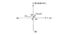
- the state in which the operating device 30 is operated can be represented by the coordinates of the tip of the operating device 30 when the operating device 30 is projected onto the XY plane parallel to the horizontal plane, as shown in FIG.
- the positive and negative directions of the X axis are the same as the front-rear direction of the electric wheelchair 1.
- the positive / negative direction of the Y axis is the same as the left / right direction of the electric wheelchair 1.
- the value of the X coordinate is a desired straight traveling speed xjs that is a straight traveling speed of the electric wheelchair 1 desired by the passenger.
- the value of the Y coordinate is a desired turning speed yjs that is a turning speed of the electric wheelchair 1 desired by the occupant.
- the desired straight traveling speed xjs and the desired turning speed yjs are output to the control device 50 every first predetermined time as operation information that is information input to the operation device 30.
- the first predetermined time is 1/25 seconds, for example.
- the detection device 40 detects an object to be detected around the electric wheelchair 1.
- the detected objects are a road surface (traveling road surface), a person, an object, etc., on which the electric wheelchair 1 will travel.
- the detection device 40 is a three-dimensional range sensor (laser range scanner (3D scanner)).
- the detection device 40 emits a laser from the detection unit 41 in the horizontal direction and the vertical direction (three-dimensionally), and the reflected wave from the detection target is received by the detection unit 41.
- the detection apparatus 40 is relative to the linear distance from the detection unit 41 to the object to be detected, the horizontal angle (with respect to the reference (for example, the straight traveling direction of the electric wheelchair 1)), and the vertical angle (for example, the horizontal direction of the electric wheelchair 1).
- the three-dimensional coordinates of the detected object can be acquired as the point cloud data D.
- Peripheral information (detected object information) is shown as point cloud data D that is three-dimensional coordinates.
- the point cloud data D represents the position / shape of the surface of the detected object.
- the detection device 40 emits a laser beam radially around the electric wheelchair 1 (in the present embodiment, forward).
- the angle range in which the laser can be emitted corresponds to an angle range in which the detection device 40 can detect the object to be detected.
- the detection device 40 acquires peripheral information every first predetermined time.
- the peripheral information acquired by the detection device 40 is output to the control device 50.
- the control device 50 controls the driving amount of the driving device 20 based on the operation information to run the electric wheelchair 1. As shown in FIG. 3, the control device 50 is connected to the drive device 20, the operation device 30, and the detection device 40.
- the control device 50 further includes an operation information acquisition unit 51, a drive control unit 52, a peripheral information acquisition unit 53, a division unit 54, a feature amount calculation unit 55, a search start point setting unit 56, and a determination unit 57.
- the operation information acquisition unit 51 acquires operation information from the operation device 30.
- the drive control unit 52 controls the driving device 20 based on the operation information acquired by the operation information acquisition unit 51 to control the traveling of the electric wheelchair 1.
- the control device 50 starts the traveling control from the time when the operation device 30 is operated and the control device 50 acquires the operation information from the operation device 30.
- the control device 50 converts the operation information (the desired straight traveling speed xjs and the desired turning speed yjs) from the operating device 30 into the straight traveling speed v and the turning speed w.
- the control device 50 calculates the straight traveling speed v from the acquired desired straight traveling speed xjs based on the first map M1 shown in FIG. 4A.
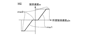
- the first map M1 shows the relationship between the desired straight traveling speed xjs and the straight traveling speed v. Moreover, the control apparatus 50 calculates the turning speed w from the acquired desired turning speed yjs based on the second map M2 shown in FIG. 4B.
- the second map M2 shows the relationship between the desired turning speed yjs and the turning speed w.
- the first map M1 has a proportional portion mv1 in which the desired straight speed xjs and the straight speed v are proportional, and the straight speed v is a constant value regardless of the magnitude of the desired straight speed xjs.
- the insensitive part mv2 is provided.
- the second map M2 has a proportional portion mw1 in which the desired turning speed yjs and the turning speed w are proportional, and the turning speed w is a constant value regardless of the magnitude of the desired turning speed yjs.
- a certain insensitive part mw2 is provided. When the turning speed w is positive, the electric wheelchair 1 turns right. On the other hand, when the turning speed w is negative, the electric wheelchair 1 turns left.
- the control device 50 controls the drive amount (rotation speed) of the drive device 20 based on the converted straight traveling speed v and turning speed w. Specifically, the converted straight traveling speed v and turning speed w are further converted into the rotational speed of the left drive wheel 13a and the rotational speed of the right drive wheel 13b.
- the magnitude of the straight traveling speed v is proportional to the magnitude of the rotational speed of each drive wheel 13a, 13b.
- the magnitude of the turning speed w is proportional to the difference in rotational speed between the left driving wheel 13a and the right driving wheel 13b.
- the relationship between the straight traveling speed v and the turning speed w and the rotational speed of each of the drive wheels 13a and 13b is derived by being measured in advance through experiments or the like. Since the drive device 20 is PWM-controlled, the control command value for the drive device 20 is calculated by the duty ratio.
- control device 50 When the control device 50 performs the traveling control, if the occupant sets the position of the operation device 30 to the neutral position, the straight wheel speed v and the turning speed w become zero, and the electric wheelchair 1 stops. In this case, the travel control of the control device 50 ends.
- the peripheral information acquisition unit 53 is an acquisition unit that acquires information about the periphery of the electric wheelchair 1 as point cloud data D shown in three dimensions from the detection device 40.
- the dividing unit 54 divides the point cloud data D acquired by the peripheral information acquiring unit 53 into a plurality of sections G that divide a predetermined plane into predetermined areas.
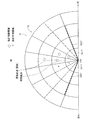
- the predetermined area is partitioned based on circular coordinates C (plane polar coordinates) as shown in FIG.
- the circular coordinates C are polar coordinates that are arranged on a predetermined plane, the position of the detection unit 41 of the detection device 40 is the origin C0, and the upper side of FIG.
- the circular coordinates C have a plurality of sections G that are partitioned at predetermined intervals in the radial direction and the circumferential direction (for example, 50 cm intervals in the radial direction and 20 ° intervals in the radial direction).
- the predetermined plane is a plane parallel to the horizontal plane when the electric wheelchair 1 is traveling on the horizontal plane, and is a reference plane including the detection unit 41.
- the origin C0 of the circular coordinates C may be, for example, the center of gravity of the electric wheelchair 1 instead of the position of the detection unit 41 of the detection device 40.
- a column close to the detection unit 41 in the radial direction is a first row
- a column on the left side in the circumferential direction is a first column.
- n indicates a row number
- m indicates a column number.
- the area G11 is an area in the first row and the first column
- the area G17 is an area in the first row and the seventh column.
- the area G21 is an area in the second row and the first column
- the area G27 is an area in the second row and the seventh column.
- the dividing unit 54 divides the point cloud data D acquired by the peripheral information acquiring unit 53 into the plurality of sections G described above. Specifically, the dividing unit 54 divides the point group data D into a plurality of sections G by projecting the point group data D onto the circular coordinates C.
- the reference position of the point cloud data D is the detection unit 41, and the dividing unit 54 can project the point cloud data D onto the circular coordinates C by matching the reference position with the origin C0 of the circular coordinates C.
- the dividing unit 54 may divide using plane orthogonal coordinates (that is, by a grid) instead of the circular coordinates C.
- the feature amount calculating unit 55 calculates, for each section Gnm divided by the dividing unit 54, a feature amount related to the feature of the section Gnm from the divided point group data Dnm that is the point group data D belonging to the section Gnm.
- the feature amount calculating unit 55 includes a merging unit 55a, an estimated surface setting unit 55b, an identifying unit 55c, a normal vector calculating unit 55d, an inclination calculating unit 55e, and a height calculating unit 55f.
- the merging unit 55a merges the area Gnm having a relatively small division point group data Dnm with the neighboring area that is the area Gnm in the vicinity of each other to form a merged area that is a new area.
- the area G37 having a relatively small division point group data D37 is merged with a neighboring area that is a neighboring area G36 to be a new merged area.
- This merged area is a target area for subsequent processing. Thereby, the number of empty areas with relatively little point cloud data can be reduced.
- the estimated surface setting unit 55b sets the estimated surface Pl from the division point group data Dnm related to the area Gnm for each area Gnm (see FIG. 6).
- the estimated plane Pl is a plane.
- the estimated plane Pl can be set by performing RANSAC or Moving Last Squares on the division point group data Dab.
- the identifying unit 55c identifies the divided point cloud data Dnm as valid point cloud data D and outliers based on the estimated surface Pl set by the estimated surface setting unit 55b. Specifically, the identification unit 55c is effective data (indicated by black circles in FIG. 6) that the shortest distance from the estimated plane Pl is smaller than the distance threshold, and the shortest distance from the estimated plane Pl is larger than the distance threshold. The point is identified as an outlier (indicated by a white circle in FIG. 6). In FIG. 6, division point group data Dnm is a certain division point group data Dab.
- the normal vector calculation unit 55d calculates a normal vector of the area Gnm from the valid point cloud data D identified by the identification unit 55c. Specifically, the normal vector calculation unit 55d calculates a centroid point (or median value) for the identified effective point cloud data D (indicated by a black circle in FIG. 7), and calculates the calculated centroid. A covariance matrix with effective point cloud data D is calculated for points (indicated by white circles in FIG. 7), and principal component analysis is performed. The normal vector calculation unit 55d sets the minimum principal component as the normal vector of the estimation plane Pl. Note that it is preferable to calculate the covariance matrix after weighting the covariance between the centroid point and each point group according to the distance between the centroid point and the point group. As a result, the normal vector can be calculated with higher accuracy while suppressing the influence of noise as much as possible.
- the inclination calculation unit 55e calculates an inclination (an angle with respect to the horizontal plane) that is one of the feature quantities of the section Gnm from the normal vector calculated by the normal vector calculation unit 55d. Since the direction of the normal vector and the plane of the zone Gnm are orthogonal to each other, the slope of the zone Gnm can be calculated from the direction of the normal vector. Specifically, for example, the inclination calculating unit 55e calculates the inclination of the section Gnm based on the inner product of the vertically upward vector and the normal vector. The inclination is a positive value when tilted forward in the traveling direction with respect to the horizontal plane (in the case of ascending slope), and negative when tilted backward in the traveling direction with respect to the horizontal plane (in the case of descending tilt). Value.
- the height calculation unit 55f calculates the height which is one of the feature quantities of the section Gnm from the effective point cloud data D identified by the identification unit 55c. Specifically, for example, the height calculation unit 55f calculates the average value or median value of the identified effective point cloud data D as the height of the area Gnm.
- the height is a positive value when it is higher than the reference plane, and a negative value when it is lower than the reference plane.
- the reference plane is, for example, a horizontal plane, and is a plane on which the wheel of the electric wheelchair 1 is installed in a state where the electric wheelchair 1 is parallel (horizontal).
- the search starting point setting unit 56 becomes a starting point for searching whether the electric wheelchair 1 is a travelable area where the electric wheelchair 1 can travel from a plurality of areas.
- An area that is within the determination range and has an inclination that belongs to the feature amount calculated by the feature amount calculation unit 55 is within the inclination determination range is set as a search starting point.
- the height determination range is set to be equal to or higher than the first height threshold and equal to or lower than the second height threshold larger than the first height threshold.
- the first height threshold is a value corresponding to, for example, a depth (concave step) that the electric wheelchair 1 can travel, and is a negative value.
- the second height threshold is a value corresponding to, for example, a height (convex step) at which the electric wheelchair 1 can travel, and is a positive value.
- the inclination determination range is set to be equal to or greater than the first inclination threshold and equal to or less than the second inclination threshold greater than the first inclination threshold.
- the first inclination threshold is a value corresponding to, for example, a downhill angle at which the electric wheelchair 1 can travel, and is a negative value.
- the second inclination threshold is, for example, a value corresponding to an uphill angle at which the electric wheelchair 1 can travel, and is a positive value.
- the search starting point setting unit 56 is within a predetermined distance from the current position of the electric wheelchair 1 among the plurality of sections G, and the height belonging to the feature amount calculated by the feature amount calculating unit 55 is the second height threshold value.
- An area that is less than (and is greater than or equal to 0) and that has an inclination belonging to the feature amount calculated by the feature amount calculation unit 55 is less than or equal to the second inclination threshold (and greater than or equal to 0) is set as a search starting point. Is preferred.
- ⁇ is a coefficient for converting the angle of the road surface into height (height threshold value Hth), and is a constant specific to the electric wheelchair 1.
- Hoffset is an offset term, and is set to an upper limit value of a step that can be overcome by the electric wheelchair 1 (a value that determines how far the vehicle can travel when the road angle is vertically upward). .
- the height threshold for detecting the search starting point can be changed according to the inclination (angle) of the area (road surface).
- the slope is capable of traveling, it can be set as a search starting point capable of traveling even when the height is greater than the step capable of traveling.
- it is possible to correctly detect (determine) a region where the vehicle can travel.
- the determination unit 57 has a similar feature amount that is close to the feature amount related to the feature of the search start point from the peripheral regions that are the neighborhood (for example, adjacent regions) around the search start point set by the search start point setting unit 56. Determine the area. That is, the determination unit 57 determines whether or not the electric wheelchair 1 is an area where the electric wheelchair 1 can travel with respect to all the areas Gnm.
- the determination unit 57 determines whether or not the area around the search starting point is a similar area by determining whether or not the difference (difference) in the feature amount between the search starting point and the surrounding area is continuous. It is determined whether or not there is, and thus whether or not the vehicle can travel. When the difference between the feature amounts of the search starting point and the surrounding area is continuous, the determination unit 57 determines that the search starting point and the surrounding area are similar areas and can be run. On the other hand, when the difference between the feature amounts of the search starting point and the surrounding area is discontinuous, the determination unit 57 determines that the search starting point and the surrounding area are dissimilar areas and cannot travel. As shown in FIG.
- a cross indicates a non-travelable area
- a circle indicates a travelable area.
- the surrounding area is an area adjacent in the vertical and horizontal directions, and does not include an area adjacent in the diagonal direction. In addition, you may make it include the area which adjoins diagonally.
- the specific method for determining whether or not they are similar is as follows. For height, which is one of the feature quantities, if the difference between the height of the search origin and the surrounding area is less than the first threshold, the difference in height between the search origin and the surrounding area is continuous. The search origin and the surrounding area are similar. On the other hand, if the difference between the height of the search origin and the surrounding area is greater than the first threshold, the difference in height between the search origin and the surrounding area is discontinuous, and the search origin and the surrounding area are non- It is similar.
- the difference between the slope of the search origin and the slope of the surrounding area is smaller than the second threshold, the difference in slope between the search origin and the surrounding area is continuous.
- the search origin and the surrounding area are similar.
- the difference between the slope of the search origin and the slope of the surrounding area is greater than the second threshold, the difference between the slope of the search origin and the surrounding area is discontinuous, and the search origin and the surrounding area are dissimilar It is.
- the search starting point and the surrounding area are similar. Otherwise, the search origin and the surrounding area are dissimilar.
- the determination unit 57 sets (updates) the most similar search origin from among the similar areas as a new search origin, and determines a new similar area from the updated search origin.
- the determination unit 57 repeatedly executes the determination of the similar area and the update of the search starting point.
- the determination unit 57 sets another new search starting point in the same manner as the search starting point setting unit 56 described above.
- the determination part 57 (control apparatus 50) memorize
- the drive control unit 52 controls the travel of the electric wheelchair 1 based on the determination result received from the determination unit 57, that is, whether the area to be traveled is a travelable area or a travel impossible area.
- control device 50 executes a program according to the flowchart.
- step S102 the control device 50 acquires information about the periphery of the electric wheelchair 1 as the point cloud data D from the detection device 40 in the same manner as the peripheral information acquisition unit 53 described above.
- step S104 the control device 50 divides all the point cloud data D acquired by the peripheral information acquisition unit 53 into a plurality of sections G that divide a predetermined plane into predetermined areas in the same manner as the division unit 54 described above. To do.
- step S106 the control device 50, for each area Gnm divided by the dividing unit 54, from the divided point group data Dnm, which is the point group data D belonging to the area Gnm, to the area Gnm in the same manner as the feature amount calculating unit 55 described above.
- the feature amount related to the feature is calculated.
- the control device 50 executes the flowchart shown in FIG. 11 as a subroutine.
- the control device 50 determines whether or not all the sections G have been processed in step S202. The control device 50 once ends this subroutine when the entire area G is processed, and advances the program to step S204 when the processing of the entire area G is not completed. In step S204, the control device 50 determines whether or not the area G is an effective area by determining whether or not the number of point groups to which it belongs is greater than the determination threshold.
- step S206 similarly to the merging unit 55a described above, the control device 50 merges the area Gnm with relatively small division point group data Dnm with the neighboring area that is the area Gnm in the vicinity of each other, and is a new area. It will be an annexed area.
- step S208 the control device 50 determines whether or not the merged area is an effective area, as in step S204.
- the control device 50 calculates the feature amount (specifically, height and slope) of the area in step S210 and subsequent steps. On the other hand, if it is determined that the area (merged area) is not an effective area, the control device 50 labels the area as an empty area in step S218 and stores that the area is an empty area.
- step S210 the control device 50 sets the estimated surface Pl from the divided point group data Dnm related to the zone Gnm for each zone Gnm, similarly to the estimated surface setting unit 55b described above.
- step S212 the control device 50 identifies the divided point group data Dnm as valid point group data D and outliers based on the estimated plane Pl set in step S210, in the same manner as the identification unit 55c described above.
- step S214 the control device 50 calculates the normal vector of the section Gnm from the valid point cloud data D identified in step S212, as with the normal vector calculation unit 55d described above.
- step S216 the control device 50 calculates an inclination, which is one of the feature quantities of the section Gnm, from the normal vector calculated in step S214, as well as the inclination calculation unit 55e described above, and height calculation unit 55f. Similarly, the height which is one of the feature quantities of the section Gnm is calculated from the effective point cloud data D identified in step S212.
- step S108 the control device 50 determines whether or not the evaluation (determination / search) of whether or not it is a travelable area for all the areas G has been completed.
- the control device 50 advances the program to step S110, and when the evaluation of all the areas G is not completed, the control apparatus 50 advances the program to step S112 and the subsequent steps.
- step S110 the control device 50 labels the area that has not been labeled, that is, the area that has not been searched (evaluated), and stores that the area is an unsearched area.
- the unsearched area is an area that is neither a travelable area nor a non-travelable area (step area, inclined area).
- step S112 the control device 50 is a travelable area where the electric wheelchair 1 can travel from among a plurality of areas, based on the feature amount calculated in step S106, in the same manner as the search start point setting unit 56 described above.
- a search starting point is set as a starting point for searching for the existence.
- the control device 50 executes the flowchart shown in FIG. 12 as a subroutine.
- step S302 the control device 50 determines whether or not the area is an empty area. If the area is an empty area, the control device 50 once ends the subroutine. If the area is not an empty area, the control device 50 advances the program to step S304. In step S304, the control device 50 determines whether or not the area is within a predetermined distance from the current position of the electric wheelchair 1. The control device 50 once ends this subroutine when the area is separated from the predetermined distance. When the area is within the predetermined distance, the control device 50 advances the program to step S306.
- step S306 the control device 50 determines whether or not the area has not been searched. If the area has already been searched, the control device 50 ends this subroutine once. If the area has not been searched, the control device 50 advances the program to step S308. In step S308, the control device 50 calculates a height threshold (or height determination range) based on the inclination.
- step S310 the control device 50 determines whether or not the area can be a search starting point. Specifically, the control device 50 determines that the height of the area is within the height determination range (for example, smaller than the second height threshold), and the inclination of the area is within the inclination determination range (for example, the first It is determined that the area can be the search starting point (if it is smaller than the two slope threshold), otherwise it is determined that the area cannot be the search starting point. If the area cannot be the search starting point, the control device 50 once ends this subroutine. If the area becomes the search starting point, the control device 50 advances the program to step S312 and sets the area as the search starting point.
- the control device 50 advances the program to step S312 and sets the area as the search starting point.
- step S114 the control device 50 determines whether or not there is a search starting point. If there is no search start point (when no search start point is set), control device 50 returns the program to step S108, and if there is a search start point (when the search start point is set), the program is moved to step S116 and thereafter. Proceed.
- step S116 and subsequent steps the control device 50, similar to the determination unit 57 described above, has a feature close to the feature amount related to the feature of the search start point from the peripheral regions that are the vicinity of the search start point set in step S112. Determine similar areas with quantities. That is, the control device 50 determines whether or not the electric wheelchair 1 is an area where the electric wheelchair 1 can travel with respect to all the areas Gnm.
- step S116 the control device 50 determines whether or not the determination (search) of the surrounding area is completed. If the determination (search) of the surrounding area is not completed, the control device 50 advances the program to step S118 and the subsequent steps. On the other hand, if the determination (search) of the surrounding area is completed, the control device 50 executes the program after step S128. Proceed to
- step S118 to 126 the control device 50 determines whether or not the area where the search has not been completed is similar to the search starting point.
- the control device 50 determines that the difference between the height of the search starting point and the height of the area is smaller than the first threshold (NO in step S118), and the difference between the inclination of the search starting point and the inclination of the area is smaller than the second threshold.
- the difference between the search starting point and the area is continuous and similar, and it is determined that the area is a travelable area (step S126).
- the control device 50 When the difference between the height of the search starting point and the height of the area is larger than the first threshold (YES in step S118), the control device 50 does not have a difference in feature amount (height) between the search starting point and the area. It is continuous and dissimilar, and it is determined that the area is a travel impossible region (large step region) with a large step (step S122). The control device 50 determines that the difference between the height of the search origin and the height of the area is smaller than the first threshold (NO in step S118), and the difference between the inclination of the search origin and the slope of the area is greater than the second threshold.
- step S120 the difference between the feature amount (inclination) is discontinuous between the search starting point and the area, and the area is a non-travelable area (steep slope area) with a large inclination. Is determined (step S124).
- step S1208 the control device 50 determines whether there is a travelable area (similar area). If there is no travelable area, control device 50 returns the program to step S108, and if there is a travelable area, the program proceeds to step S130.
- step S130 control device 50 selects the one that is most similar to the search starting point from among a plurality of similar areas, and in step S132, sets (updates) the selected area as a new search starting point. Thereafter, the control device 50 returns the program to step S116, and determines a new similar area from the updated search starting point.
- the electric wheelchair 1 (moving body) according to the present embodiment is a moving body that travels by being driven by the driving device 20.
- the electric wheelchair 1 has a peripheral information acquisition unit 53 (acquisition unit) that acquires information around the electric wheelchair 1 as three-dimensional point cloud data, and the point cloud data acquired by the peripheral information acquisition unit 53 is predetermined.
- a dividing unit 54 that divides a plane into a plurality of sections G divided into predetermined areas, and features of the section G from the divided point group data that is point group data belonging to the section G for each section G divided by the dividing section 54
- the feature amount calculation unit 55 that calculates the feature amount according to the feature amount, and the travelable area where the electric wheelchair 1 can travel from among the plurality of areas G based on the feature amount calculated by the feature amount calculation unit 55.
- a search starting point setting unit 56 that sets a starting point for searching for the search point, and a feature of the search starting point from among the surrounding areas that are the surrounding area G of the search starting point set by the search starting point setting unit 56
- a determination unit 57 a similar region having a close feature quantity to the feature quantity relating comprises a.
- the similar area can be determined based on the feature amount calculated for each area G from the area G around the search start point set in advance, with the search start point as a reference. That is, the travelable area of the electric wheelchair 1 can be determined based on the search starting point. As a result, it is possible to provide the electric wheelchair 1 that can suppress the influence of the shape of the road surface on which the electric wheelchair 1 is traveling and can recognize the step and inclination of the road surface of the electric wheelchair 1 with higher accuracy.
- the posture of the electric wheelchair 1 or the detection device 40 is used to determine whether or not the area around the search start point is similar to the search start point using the area (search start point) determined to be a road surface that can be traveled as a comparison source. Even if there is a change, the interrelationship between the areas does not change. Therefore, the influence of the disturbance of the posture change of the electric wheelchair 1 or the detection device 40 due to the road surface gradient or unevenness can be suppressed. As a result, the electric wheelchair 1 can recognize the step or inclination of the traveling road surface of the electric wheelchair 1 with higher accuracy.
- the feature amount calculation unit 55 performs the division based on the estimation plane set by the estimation plane setting unit 55b and the estimation plane setting unit 55b that sets the estimation plane from the division point cloud data related to the section G for each section G.
- An identification unit 55c that distinguishes point cloud data into valid point cloud data and outliers, and a normal vector calculation unit 55d that computes a normal vector of the zone G from the valid point cloud data identified by the identification unit 55c;
- the slope calculation unit 55e that calculates a slope, which is one of the feature quantities of the zone G, from the normal vector calculated by the normal vector calculation unit 55d, and the zone G from the effective point cloud data identified by the identification unit 55c.
- a height calculation unit 55f that calculates a height that is one of the feature amounts of According to this, for each zone G, the feature amount (height and slope) related to the zone G can be calculated with high accuracy. As a result, the step or slope (steep slope) of the traveling road surface of the electric wheelchair 1 can be recognized with higher accuracy. In addition, even if the road surface is uneven or the road surface is noisy, the normal vector of the area can be calculated with high accuracy, so that the travelable area can be recognized correctly and the travelable area can be expanded. it can.
- the feature amount calculation unit 55 further includes a merging unit 55a that merges the area G having relatively little division point cloud data with the neighboring area that is the neighboring area G to form a merged area that is a new area G. And calculating the slope and height of the merged area merged by the merged portion 55a. According to this, even for the area G having relatively small division point group data, the number of measurement points can be increased by merging with the adjacent area G, and the feature amount related to the area G can be calculated with high accuracy. . As a result, the step and inclination of the traveling road surface of the electric wheelchair 1 can be recognized more accurately.
- the search starting point setting unit 56 is within a predetermined distance from the current position of the electric wheelchair 1 among the plurality of sections G, and the height belonging to the feature amount calculated by the feature amount calculation unit 55 is within the height determination range. And the area G in which the slope belonging to the feature quantity calculated by the feature quantity calculation unit 55 is within the slope determination range is set as the search starting point. According to this, the search starting point can be set accurately. As a result, the step and inclination of the traveling road surface of the electric wheelchair 1 can be recognized more accurately.
- the size of the height determination range (each height threshold described above) is set according to the inclination calculated by the feature amount calculation unit 55. According to this, the search starting point can be set more accurately. As a result, the step and inclination of the traveling road surface of the electric wheelchair 1 can be recognized more accurately. That is, it is possible to accurately recognize a gentle slope that can be traveled, to enlarge a travelable region, and to improve convenience.
- feature quantities for example, height information and inclination information
- the search starting point setting unit calculates (corrects) the feature amount (for example, height information and inclination information) using information from another sensor (for example, acceleration sensor), and calculates (corrects) in this way.
- the search starting point may be set based on the feature amount. In this case, the accuracy of the calculated feature amount is improved, and the search starting point can be set more appropriately.
- SYMBOLS 1 Electric wheelchair (mobile body) 10 ... Wheelchair main body, 20 ... Drive apparatus, 30 ... Operation apparatus, 40 ... Detection apparatus, 41 ... Detection part, 50 ... Control apparatus, 51 ... Operation information acquisition part, 52 ... Drive control , 53 ... Peripheral information acquisition part, 54 ... Dividing part, 55 ... Feature quantity calculation part, 55a ... Merger part, 55b ... Estimated surface setting part, 55c ... Identification part, 55d ... Normal vector calculation part, 55e ... Inclination calculation Part 55f ... height calculation part 56 ... search starting point setting part 57 ... determination part D ... point cloud data G ... area (grid).
Landscapes
- Engineering & Computer Science (AREA)
- Power Engineering (AREA)
- Transportation (AREA)
- Mechanical Engineering (AREA)
- Life Sciences & Earth Sciences (AREA)
- Sustainable Development (AREA)
- Sustainable Energy (AREA)
- Radar, Positioning & Navigation (AREA)
- Aviation & Aerospace Engineering (AREA)
- Remote Sensing (AREA)
- Physics & Mathematics (AREA)
- General Physics & Mathematics (AREA)
- Automation & Control Theory (AREA)
- Control Of Position, Course, Altitude, Or Attitude Of Moving Bodies (AREA)
- Electric Propulsion And Braking For Vehicles (AREA)
- Traffic Control Systems (AREA)
Abstract
移動体が走行している路面形状の影響を抑え、移動体の走行路面の段差や傾斜をより精度よく認識することができる移動体を提供する。 電動車椅子は、取得された点群データが分割部によって分割された区域毎に、区域に属する点群データである分割点群データから区域の特徴に係る特徴量をそれぞれ算出する特徴量算出部と、特徴量算出部によって算出された特徴量に基づいて、複数の区域のなかから電動車椅子が走行可能である走行可能区域であるかを探索するために起点となる探索起点を設定する探索起点設定部と、探索起点設定部によって設定された探索起点の周辺の区域である周辺区域のなかから、探索起点の特徴に係る特徴量に近い特徴量を有する類似区域を判定する判定部と、を備えている。
Description
本発明は、移動体に関する。
移動体の一形式として、特許文献1に示されているものが知られている。特許文献1の図1に示されているように、移動体は、移動体の路面データ取得手段で少なくとも高さデータを含む路面データを取得するステップと、取得した路面データを高さ順に並べ替えるステップと、並べ替えた路面データの変化点を抽出するステップと、変化点を境に障害を認識するステップと、を備えている。これにより、精度良く障害を認識することができるようになっている。
また、移動体の他の一形式として、特許文献2に示されているものが知られている。特許文献2の図1に示されているように、移動体は、移動台車1の前方床面と移動本体との距離を測定する距離センサ4と、移動台車1に移動量測定手段9を設け、前方床面6及び移動台車1間の測定距離と設定値との偏差が継続して基準量を超えた場合に、移動量測定手段9によって同基準量を超えた後の移動距離を測定し、当該移動距離が基準移動量を超えた時に走行不能と判定して移動台車1を停止させるように構成されている。これにより、走行経路の前方に段差や傾斜を検知した場合に、段差の高さや幅又は傾斜の程度を認識することで必要以上の停止をすることがなく、低い段差や狭い幅の溝を走行可能と判断して走行を継続することができるようになっている。
上述した特許文献1においては、移動体が走行する路面(走行路面)の段差や傾斜をより精度よく認識することが要請されている。また、上述した特許文献2においては、移動体が走行中であることを前提に走行路面の段差や傾斜を検知することができるため、移動体が走行している路面(移動体が現在走行している地点)が平面である場合には、走行路面(移動体の進行方向の路面)の段差や傾斜を検知することができるものの、移動体が走行している路面が平面でない場合(例えば上り坂、下り坂、凸凹面)には、走行路面の段差や傾斜を精度よく検知することができないという問題があった。
そこで、本発明は、上述した課題を解消するためになされたもので、移動体が走行している路面形状の影響を抑え、移動体の走行路面の段差や傾斜をより精度よく認識することができる移動体を提供することを目的とする。
上記の課題を解決するため、請求項1に係る移動体は、駆動装置による駆動によって走行する移動体であって、移動体の周辺の情報を三次元で示される点群データとして取得する取得部と、取得部によって取得された点群データを、所定平面を所定の領域に区画した複数の区域に分割する分割部と、分割部によって分割された区域毎に、区域に属する点群データである分割点群データから区域の特徴に係る特徴量をそれぞれ算出する特徴量算出部と、特徴量算出部によって算出された特徴量に基づいて、複数の区域のなかから移動体が走行可能である走行可能区域であるかを探索するために起点となる探索起点を設定する探索起点設定部と、探索起点設定部によって設定された探索起点の周辺の区域である周辺区域のなかから、探索起点の特徴に係る特徴量に近い特徴量を有する類似区域を判定する判定部と、を備えている。
これによれば、先に設定された探索起点の周辺の区域のなかから、探索起点を基準に、区域毎に算出された特徴量に基づいて、類似区域を判定することができる。すなわち、探索起点を基準に移動体の走行可能区域を判定することができる。その結果、移動体が走行している路面形状の影響を抑え、移動体の走行路面の段差や傾斜をより精度よく認識することができる移動体を提供することができる。
以下、本発明による移動体の一実施形態について図面を参照して説明する。本実施形態における移動体として、図1に示す電動車椅子1を例に挙げて説明する。なお、本明細書においては説明の便宜上、図1における上側および下側をそれぞれ電動車椅子1の上方および下方とし、同じく左下側および右上側をそれぞれ電動車椅子1の前方および後方とし、同じく左上側および右下側を、それぞれ電動車椅子1の右方および左方として説明する。また、図1には、各方向を示す矢印を示している。
電動車椅子1は、車椅子本体10、駆動装置20、操作装置30、検知装置40および制御装置50を備えている。電動車椅子1は、乗員が搭乗するものであり、乗員による操作装置30への入力に従って駆動される駆動装置20によって走行する移動体である。駆動装置20、操作装置30、検知装置40および制御装置50は、車椅子本体10に取り付けられている。なお、移動体は、乗員が搭乗しその乗員によって操作されるものに限られず、乗員が搭乗しない自律型のものもある。
車椅子本体10は、フレーム11、乗員が着座する座席12および車輪13を備えている。座席12および車輪13は、フレーム11に取り付けられている。車輪13は、回転軸回りに回転可能に構成されている。車輪13は、車椅子本体10の左右両側に配設され、駆動装置20によって駆動される左駆動輪13aおよび右駆動輪13b、並びに、電動車椅子1の走行を補助する左補助輪13cおよび右補助輪13dを備えている。
駆動装置20は、各駆動輪13a,13bをそれぞれ回転駆動させて、電動車椅子1を走行させるものである。駆動装置20は、例えば、電動モータ(図示なし)と減速機(図示なし)とを組み合わせることにより構成されている。駆動装置20は、各駆動輪13a,13bにそれぞれ1つずつ(合計2つ)設けられている。
操作装置30は、電動車椅子1の直進速度vおよび旋回速度wを指示するために乗員によって操作されるものである。直進速度vは、電動車椅子1の前方向(正面方向)における電動車椅子1の速度である。旋回速度wは、電動車椅子1の位置する場所において、電動車椅子1が電動車椅子1の重心を中心に旋回する角速度である。本実施形態において、操作装置30は、ジョイスティックである。操作装置30は、操作されていない位置(以下、ニュートラル位置とする)において、鉛直方向に起立した状態で位置決めされている。操作装置30は、ニュートラル位置から乗員に傾けられることにより操作される。操作装置30が操作された状態は、図2に示すように、操作装置30を水平面と平行なXY平面に投影したときにおける操作装置30の先端の座標によって表すことができる。X軸の正負方向は、電動車椅子1の前後方向と同じである。Y軸の正負方向は、電動車椅子1の左右方向と同じである。X座標の値は、乗員が所望する電動車椅子1の直進速度である所望直進速度xjsである。Y座標の値は、乗員が所望する電動車椅子1の旋回速度である所望旋回速度yjsである。所望直進速度xjsおよび所望旋回速度yjsは、操作装置30に入力された情報である操作情報として、制御装置50に第一所定時間毎に出力される。第一所定時間は、例えば、1/25秒である。
検知装置40は、電動車椅子1の周囲にある被検知物を検知するものである。被検知物は、電動車椅子1がこれから走行する路面(走行路面)、人、物などである。
検知装置40は、3次元測域センサ(レーザーレンジスキャナー(3Dスキャナー))である。検知装置40は、検知部41からレーザーを水平方向および上下方向に(三次元的に)発射して、被検知物からの反射波を検知部41にて受信する。これにより、検知装置40は、検知部41から被検知物までの直線距離、水平角度(基準(例えば電動車椅子1の直進方向)に対する)、垂直角度(基準(例えば電動車椅子1の水平方向)に対する)を取得することができ、ひいては被検知物に係る三次元座標を点群データDとして取得することができる。周辺情報(被検知物情報)が三次元座標である点群データDとして示されている。点群データDは、被検知物の表面の位置・形状を表している。検知装置40は、レーザーを電動車椅子1の周囲(本実施形態では前方)に放射状に発射する。レーザーの発射可能な角度範囲は、検知装置40が被検知物を検知可能な角度範囲に相当する。検知装置40は、例えば、第一所定時間毎に周辺情報を取得する。検知装置40が取得した周辺情報は、制御装置50に出力される。
検知装置40は、3次元測域センサ(レーザーレンジスキャナー(3Dスキャナー))である。検知装置40は、検知部41からレーザーを水平方向および上下方向に(三次元的に)発射して、被検知物からの反射波を検知部41にて受信する。これにより、検知装置40は、検知部41から被検知物までの直線距離、水平角度(基準(例えば電動車椅子1の直進方向)に対する)、垂直角度(基準(例えば電動車椅子1の水平方向)に対する)を取得することができ、ひいては被検知物に係る三次元座標を点群データDとして取得することができる。周辺情報(被検知物情報)が三次元座標である点群データDとして示されている。点群データDは、被検知物の表面の位置・形状を表している。検知装置40は、レーザーを電動車椅子1の周囲(本実施形態では前方)に放射状に発射する。レーザーの発射可能な角度範囲は、検知装置40が被検知物を検知可能な角度範囲に相当する。検知装置40は、例えば、第一所定時間毎に周辺情報を取得する。検知装置40が取得した周辺情報は、制御装置50に出力される。
制御装置50は、操作情報に基づいて、駆動装置20の駆動量を制御して電動車椅子1を走行させるものである。制御装置50は、図3に示すように、駆動装置20、操作装置30および検知装置40が接続されている。さらに、制御装置50は、操作情報取得部51、駆動制御部52、周辺情報取得部53、分割部54、特徴量算出部55、探索起点設定部56、および判定部57を備えている。
操作情報取得部51は、操作装置30からの操作情報を取得する。駆動制御部52は、操作情報取得部51によって取得された操作情報に基づいて駆動装置20を制御して電動車椅子1の走行を制御する。
具体的には、操作装置30が操作され、操作装置30からの操作情報を制御装置50が取得した時点から、制御装置50は、走行制御を開始する。制御装置50は、操作装置30からの操作情報(所望直進速度xjsおよび所望旋回速度yjs)を、直進速度vおよび旋回速度wに変換する。制御装置50は、取得した所望直進速度xjsから、図4Aに示す第一マップM1に基づいて、直進速度vを算出する。第一マップM1は、所望直進速度xjsと直進速度vとの関係を示したものである。また、制御装置50は、取得した所望旋回速度yjsから、図4Bに示す第二マップM2に基づいて、旋回速度wを算出する。第二マップM2は、所望旋回速度yjsと旋回速度wとの関係を示したものである。
具体的には、操作装置30が操作され、操作装置30からの操作情報を制御装置50が取得した時点から、制御装置50は、走行制御を開始する。制御装置50は、操作装置30からの操作情報(所望直進速度xjsおよび所望旋回速度yjs)を、直進速度vおよび旋回速度wに変換する。制御装置50は、取得した所望直進速度xjsから、図4Aに示す第一マップM1に基づいて、直進速度vを算出する。第一マップM1は、所望直進速度xjsと直進速度vとの関係を示したものである。また、制御装置50は、取得した所望旋回速度yjsから、図4Bに示す第二マップM2に基づいて、旋回速度wを算出する。第二マップM2は、所望旋回速度yjsと旋回速度wとの関係を示したものである。
第一マップM1は、図4Aに示すように、所望直進速度xjsと直進速度vとが、比例する比例部mv1と、所望直進速度xjsの大きさにかかわらず直進速度vが一定の値である不感部mv2備えている。直進速度vが正である場合、電動車椅子1が前進する。一方、直進速度vが負である場合、電動車椅子1が後退する。また、第二マップM2は、図4Bに示すように、所望旋回速度yjsと旋回速度wとが比例する比例部mw1と、所望旋回速度yjsの大きさにかかわらず旋回速度wが一定の値である不感部mw2を備えている。旋回速度wが正である場合、電動車椅子1が右旋回する。一方、旋回速度wが負である場合、電動車椅子1が左旋回する。
制御装置50は、変換された直進速度vおよび旋回速度wに基づいて、駆動装置20の駆動量(回転数)を制御する。具体的には、変換された直進速度vおよび旋回速度wが、左駆動輪13aの回転速度および右駆動輪13bの回転速度にさらに変換される。直進速度vの大きさは、各駆動輪13a,13bの回転速度の大きさに比例する。また、旋回速度wの大きさは、左駆動輪13aと右駆動輪13bとの回転速度の差の大きさに比例する。直進速度vおよび旋回速度wと各駆動輪13a,13bの回転速度との関係は、予め実験等により実測されて導出されている。なお、駆動装置20がPWM制御されているため、駆動装置20の制御指令値は、デューティ比にて算出される。
制御装置50が走行制御を行っている際に、乗員が操作装置30の位置をニュートラル位置にした場合、直進速度vおよび旋回速度wがゼロとなることで、電動車椅子1が停止する。この場合、制御装置50の走行制御が終了する。
周辺情報取得部53は、検知装置40から、電動車椅子1の周辺の情報を三次元で示される点群データDとして取得する取得部である。
分割部54は、周辺情報取得部53によって取得された点群データDを、所定平面を所定の領域に区画した複数の区域Gに分割する。本実施形態では、所定の領域は、図5に示すように、円座標C(平面極座標)に基づいて区画されている。円座標Cは、所定平面に配設され、検知装置40の検知部41の位置を原点C0とするとともに、図5の上側を電動車椅子1の前方とした極座標である。円座標Cは、径方向および周方向に所定間隔(例えば、径方向に50cm間隔および径方向に20°間隔)に区画された複数の区域Gを有している。所定平面は、電動車椅子1が水平面を走行している場合、水平面と平行になる平面であり、検知部41を含む基準平面である。
分割部54は、周辺情報取得部53によって取得された点群データDを、所定平面を所定の領域に区画した複数の区域Gに分割する。本実施形態では、所定の領域は、図5に示すように、円座標C(平面極座標)に基づいて区画されている。円座標Cは、所定平面に配設され、検知装置40の検知部41の位置を原点C0とするとともに、図5の上側を電動車椅子1の前方とした極座標である。円座標Cは、径方向および周方向に所定間隔(例えば、径方向に50cm間隔および径方向に20°間隔)に区画された複数の区域Gを有している。所定平面は、電動車椅子1が水平面を走行している場合、水平面と平行になる平面であり、検知部41を含む基準平面である。
なお、円座標Cの原点C0は、検知装置40の検知部41の位置とする代わりに、例えば電動車椅子1の重心としても良い。
また、分割された区域Gnmは、径方向に検知部41に近い列を第一行とし、周方向の左側の列を第一列とする。nは行番号を示し、mは列番号を示す。区域G11は、第一行、第一列の区域であり、区域G17は、第一行、第七列の区域である。区域G21は、第二行、第一列の区域であり、区域G27は、第二行、第七列の区域である。
また、分割された区域Gnmは、径方向に検知部41に近い列を第一行とし、周方向の左側の列を第一列とする。nは行番号を示し、mは列番号を示す。区域G11は、第一行、第一列の区域であり、区域G17は、第一行、第七列の区域である。区域G21は、第二行、第一列の区域であり、区域G27は、第二行、第七列の区域である。
分割部54は、周辺情報取得部53によって取得された点群データDを、上述した複数の区域Gに分割する。具体的には、分割部54は、点群データDを円座標Cに投影することにより、複数の区域Gに分割する。点群データDの基準位置は検知部41であり、分割部54は、この基準位置を円座標Cの原点C0に合わすことにより、点群データDを円座標Cに投影することができる。
なお、分割部54は、円座標Cに代えて、平面直交座標を使用して(すなわち格子(グリッド)によって)分割するようにしてもよい。
なお、分割部54は、円座標Cに代えて、平面直交座標を使用して(すなわち格子(グリッド)によって)分割するようにしてもよい。
特徴量算出部55は、分割部54によって分割された区域Gnm毎に、区域Gnmに属する点群データDである分割点群データDnmから区域Gnmの特徴に係る特徴量をそれぞれ算出する。具体的には、特徴量算出部55は、併合部55a、推定面設定部55b、識別部55c、法線ベクトル算出部55d、傾斜算出部55e、および高さ算出部55fを備えている。
併合部55aは、分割点群データDnmが比較的少ない区域Gnmを、互いに近傍にある区域Gnmである近傍区域と併合(マージ)して新たな区域である併合区域とする。例えば、分割点群データD37が比較的少ない区域G37は、近傍にある区域G36である近傍区域と併合して新たな区域である併合区域とする。この併合区域が、以降の処理の対象区域である。これにより、点群データの比較的少ない空区域の数を減少させることができる。
推定面設定部55bは、区域Gnm毎に区域Gnmに係る分割点群データDnmから推定面Plを設定する(図6参照)。推定面Plは平面である。推定面Plは、分割点群データDabに対してRANSACやMoving Least Squaersを行うことにより設定することができる。
識別部55cは、推定面設定部55bによって設定された推定面Plに基づいて、分割点群データDnmを有効な点群データDと外れ値とに識別する。具体的には、識別部55cは、推定面Plからの最短距離が距離閾値より小さい点が有効データ(図6にて黒丸で示す)であり、推定面Plからの最短距離が距離閾値より大きい点が外れ値(図6にて白丸で示す)であると識別する。なお、図6において、分割点群データDnmはある分割点群データDabである。
法線ベクトル算出部55dは、識別部55cによって識別された有効な点群データDから区域Gnmの法線ベクトルを算出する。具体的には、法線ベクトル算出部55dは、識別された有効な点群データD(図7にて黒丸で示す)に対して、重心点(または中央値)を算出し、この算出した重心点(図7にて白丸で示す)に対して有効な点群データDとの共分散行列を算出し、主成分分析を行う。法線ベクトル算出部55dは、最小主成分を推定面Plの法線ベクトルとして設定する。なお、重心点と各点群との共分散に対して、重心点と点群との距離に応じた重み付けを行った上で共分散行列を算出するのが好ましい。これにより、ノイズの影響をできるだけ抑制して、法線ベクトルをさらに精度よく算出することができる。
傾斜算出部55eは、法線ベクトル算出部55dによって算出された法線ベクトルから区域Gnmの特徴量の一つである傾斜(水平面に対する角度)を算出する。法線ベクトルの方向と区域Gnmの平面とは直交する関係があるため、区域Gnmの傾斜は、法線ベクトルの方向から算出することができる。具体的には、例えば傾斜算出部55eは、鉛直上向きベクトルと法線ベクトルとの内積により区域Gnmの傾斜を算出する。傾斜は、水平面に対して進行方向手前側に傾斜する場合(上り傾斜の場合)には正の値となり、水平面に対して進行方向奥側に傾斜する場合(下り傾斜の場合)には負の値となる。
高さ算出部55fは、識別部55cによって識別された有効な点群データDから区域Gnmの特徴量の一つである高さを算出する。具体的には、例えば高さ算出部55fは、識別された有効な点群データDの平均値または中央値をその区域Gnmの高さとして算出する。高さは、基準面より高い場合には正の値となり、基準面より低い場合には負の値となる。なお、基準面は、例えば水平面であり、電動車椅子1が平行(水平)状態で電動車椅子1の車輪が設置する面である。
探索起点設定部56は、特徴量算出部55によって算出された特徴量に基づいて、複数の区域のなかから電動車椅子1が走行可能である走行可能区域であるかを探索するために起点となる探索起点を設定する。具体的には、探索起点設定部56は、複数の区域Gのうち、電動車椅子1の現在位置から所定距離内であり、特徴量算出部55によって算出された特徴量に属する高さが高さ判定範囲内であり、かつ、特徴量算出部55によって算出された特徴量に属する傾斜が傾斜判定範囲内である区域を、探索起点に設定する。
なお、高さ判定範囲は、第一高さ閾値以上であり、かつ第一高さ閾値より大きい第二高さ閾値以下に設定されている。第一高さ閾値は、例えば電動車椅子1が走行可能な深さ(凹状段差)に相当する値であり、負の値である。第二高さ閾値は、例えば電動車椅子1が走行可能な高さ(凸状段差)に相当する値であり、正の値である。
また、傾斜判定範囲は、第一傾斜閾値以上であり、かつ第一傾斜閾値より大きい第二傾斜閾値以下に設定されている。第一傾斜閾値は、例えば電動車椅子1が走行可能な下り坂の角度に相当する値であり、負の値である。第二傾斜閾値は、例えば電動車椅子1が走行可能な上り坂の角度に相当する値であり、正の値である。
例えば、探索起点設定部56は、複数の区域Gのうち、電動車椅子1の現在位置から所定距離内であり、特徴量算出部55によって算出された特徴量に属する高さが第二高さ閾値以下であり(かつ0以上である)、かつ、特徴量算出部55によって算出された特徴量に属する傾斜が第二傾斜閾値以下である(かつ0以上である)区域を、探索起点に設定するのが好ましい。
なお、高さ判定範囲は、第一高さ閾値以上であり、かつ第一高さ閾値より大きい第二高さ閾値以下に設定されている。第一高さ閾値は、例えば電動車椅子1が走行可能な深さ(凹状段差)に相当する値であり、負の値である。第二高さ閾値は、例えば電動車椅子1が走行可能な高さ(凸状段差)に相当する値であり、正の値である。
また、傾斜判定範囲は、第一傾斜閾値以上であり、かつ第一傾斜閾値より大きい第二傾斜閾値以下に設定されている。第一傾斜閾値は、例えば電動車椅子1が走行可能な下り坂の角度に相当する値であり、負の値である。第二傾斜閾値は、例えば電動車椅子1が走行可能な上り坂の角度に相当する値であり、正の値である。
例えば、探索起点設定部56は、複数の区域Gのうち、電動車椅子1の現在位置から所定距離内であり、特徴量算出部55によって算出された特徴量に属する高さが第二高さ閾値以下であり(かつ0以上である)、かつ、特徴量算出部55によって算出された特徴量に属する傾斜が第二傾斜閾値以下である(かつ0以上である)区域を、探索起点に設定するのが好ましい。
なお、上述した各高さ閾値は、特徴量算出部55によって算出された傾斜に応じて設定されている。具体的には、高さ閾値Hthは、図8に示すマップまたは下記数1から、区域Gの傾斜An1(路面の角度)に対応した値として算出される。
(数1)
Hth=α×An1+Hoffset
ここで、αは、路面の角度を高さ(高さ閾値Hth)に変換するための係数であり、電動車椅子1固有の定数である。また、Hoffsetは、オフセット項であり、電動車椅子1が乗り越え可能な段差の上限値に設定されている(路面の角度が垂直上向きのときに、どこまで走行可能と設定するかを決める値である)。
(数1)
Hth=α×An1+Hoffset
ここで、αは、路面の角度を高さ(高さ閾値Hth)に変換するための係数であり、電動車椅子1固有の定数である。また、Hoffsetは、オフセット項であり、電動車椅子1が乗り越え可能な段差の上限値に設定されている(路面の角度が垂直上向きのときに、どこまで走行可能と設定するかを決める値である)。
これによれば、探索起点を検出するための高さ閾値を、その区域(路面)の傾斜(角度)に応じて変化させることができる。その結果、走行可能な傾斜であれば、高さが走行可能な段差より大きい場合であっても、走行可能な探索起点として設定できる。ひいては、走行可能な領域を正しく検出(判定)することができる。
判定部57は、探索起点設定部56によって設定された探索起点の周辺の区域(例えば、隣り合う区域)である周辺区域のなかから、探索起点の特徴に係る特徴量に近い特徴量を有する類似区域を判定する。すなわち、判定部57は、全ての区域Gnmに対して電動車椅子1が走行可能な領域であるか否かを判定する。
具体的には、判定部57は、探索起点の周辺の区域が、探索起点と周辺の区域の両方の特徴量の違い(差分)が連続であるか否かを判定することにより、類似区域であるか否か、ひいては走行可能であるか否かを判定する。探索起点と周辺の区域の特徴量の違いが連続である場合、判定部57は、探索起点と周辺の区域は類似区域であり、走行可能であると判定する。一方、探索起点と周辺の区域の特徴量の違いが不連続である場合、判定部57は、探索起点と周辺の区域は非類似区域であり、走行不可であると判定する。図9に示すように、×印が走行不可な区域を示し、○印が走行可能な区域を示す。周辺の区域は、縦横方向に隣接する区域であり、斜め方向に隣接する区域は含まない。なお、斜め方向に隣接する区域を含むようにしてもよい。
類似であるか否かの具体的な判定方法は、次のとおりである。特徴量の一つである高さについては、探索起点の高さと周辺の区域の高さとの差分が第一閾値より小さい場合には、探索起点と周辺の区域の高さの違いが連続であり、探索起点と周辺の区域は類似である。一方、探索起点の高さと周辺の区域の高さとの差分が第一閾値より大きい場合には、探索起点と周辺の区域の高さの違いが不連続であり、探索起点と周辺の区域は非類似である。
さらに、特徴量の一つである傾斜については、探索起点の傾斜と周辺の区域の傾斜との差分が第二閾値より小さい場合には、探索起点と周辺の区域の傾斜の違いが連続であり、探索起点と周辺の区域は類似である。一方、探索起点の傾斜と周辺の区域の傾斜との差分が第二閾値より大きい場合には、探索起点と周辺の区域の傾斜の違いが不連続であり、探索起点と周辺の区域は非類似である。
このように、特徴量である高さおよび傾斜の両方が連続である場合、探索起点と周辺の区域は類似である。それ以外の場合、探索起点と周辺の区域は非類似である。
このように、特徴量である高さおよび傾斜の両方が連続である場合、探索起点と周辺の区域は類似である。それ以外の場合、探索起点と周辺の区域は非類似である。
さらに、判定部57は、類似区域のなかから最も探索起点に類似するものを新たな探索起点に設定(更新)し、更新した探索起点を起点に新たな類似区域を判定する。判定部57は、以上の類似区域の判定、探索起点の更新を繰り返し実行する。なお、類似区域が発見できない場合(すなわち探索起点の更新ができない場合)、判定部57は、上述した探索起点設定部56と同様に、新たに別の探索起点を設定する。また、判定部57(制御装置50)は、判定部57によって類似区域と判定された区域を記憶部に記憶する。
また、判定部57は、その判定結果を駆動制御部52に送信する。駆動制御部52は、判定部57から受けた判定結果すなわち走行しようとする区域が走行可能区域であるか走行不可領域であるかに基づいて、電動車椅子1の走行を制御する。
また、判定部57は、その判定結果を駆動制御部52に送信する。駆動制御部52は、判定部57から受けた判定結果すなわち走行しようとする区域が走行可能区域であるか走行不可領域であるかに基づいて、電動車椅子1の走行を制御する。
さらに、上述した移動体に係る作動特に走行可能な領域を判定する制御について図10に示すフローチャートに沿って説明する。制御装置50は、そのフローチャートに沿ったプログラムを実行する。
制御装置50は、ステップS102において、上述した周辺情報取得部53と同様に、検知装置40から電動車椅子1の周辺の情報を点群データDとして取得する。
制御装置50は、ステップS104において、上述した分割部54と同様に、周辺情報取得部53によって取得された全ての点群データDを、所定平面を所定の領域に区画した複数の区域Gに分割する。
制御装置50は、ステップS104において、上述した分割部54と同様に、周辺情報取得部53によって取得された全ての点群データDを、所定平面を所定の領域に区画した複数の区域Gに分割する。
制御装置50は、ステップS106において、上述した特徴量算出部55と同様に、分割部54によって分割された区域Gnm毎に、区域Gnmに属する点群データDである分割点群データDnmから区域Gnmの特徴に係る特徴量をそれぞれ算出する。具体的には、制御装置50は、図11に示すフローチャートをサブルーチンとして実行する。
制御装置50は、ステップS202において、全区域Gを処理したか否かを判定する。制御装置50は、全区域Gを処理した場合、本サブルーチンを一旦終了し、全区域Gの処理が完了していない場合、プログラムをステップS204に進める。制御装置50は、ステップS204において、属する点群数が判定閾値より多いか否かを判定することにより、区域Gが有効区域であるか否かを判定する。
制御装置50は、ステップS206において、上述した併合部55aと同様に、分割点群データDnmが比較的少ない区域Gnmを、互いに近傍にある区域Gnmである近傍区域と併合して新たな区域である併合区域とする。制御装置50は、ステップS208において、ステップS204と同様に、併合区域が有効区域であるか否かを判定する。
区域(併合区域)が有効区域であると判定された場合、制御装置50は、ステップS210以降において区域の特徴量(具体的には高さおよび傾斜)を算出する。一方、区域(併合区域)が有効区域でないと判定された場合、制御装置50は、ステップS218において、当該区域に空区域のラベルを貼り当該区域が空区域である旨を記憶する。
制御装置50は、ステップS210において、上述した推定面設定部55bと同様に、区域Gnm毎に区域Gnmに係る分割点群データDnmから推定面Plを設定する。制御装置50は、ステップS212において、上述した識別部55cと同様に、ステップS210によって設定された推定面Plに基づいて、分割点群データDnmを有効な点群データDと外れ値とに識別する。制御装置50は、ステップS214において、上述した法線ベクトル算出部55dと同様に、ステップS212によって識別された有効な点群データDから区域Gnmの法線ベクトルを算出する。制御装置50は、ステップS216において、上述した傾斜算出部55eと同様に、ステップS214によって算出された法線ベクトルから区域Gnmの特徴量の一つである傾斜を算出するとともに、高さ算出部55fと同様に、ステップS212によって識別された有効な点群データDから区域Gnmの特徴量の一つである高さを算出する。
制御装置50は、ステップS108において、全区域Gに対して走行可能な区域であるか否かの評価(判定・探索)が終了したか否かを判定する。制御装置50は、全区域Gの評価を完了した場合、プログラムをステップS110に進め、全区域Gの評価が完了していない場合、プログラムをステップS112以降に進める。制御装置50は、ステップS110において、ラベリングがされていない区域すなわち探索(評価)が行われていない区域に未探索区域である旨のラベルを貼り当該区域が未探索区域である旨を記憶する。未探索区域は、走行可能区域、走行不能区域(段差区域、傾斜区域)のいずれでもない区域である。
制御装置50は、ステップS112において、上述した探索起点設定部56と同様に、ステップS106によって算出された特徴量に基づいて、複数の区域のなかから電動車椅子1が走行可能である走行可能区域であるかを探索するために起点となる探索起点を設定する。具体的には、制御装置50は、図12に示すフローチャートをサブルーチンとして実行する。
制御装置50は、ステップS302において、当該区域が空区域であるか否かを判定する。制御装置50は、当該区域が空区域である場合、本サブルーチンを一旦終了し、当該区域が空区域でない場合、プログラムをステップS304に進める。
制御装置50は、ステップS304において、当該区域が電動車椅子1の現在位置から所定距離内であるか否かを判定する。制御装置50は、当該区域が所定距離より離れている場合、本サブルーチンを一旦終了し、当該区域が所定距離内である場合、プログラムをステップS306に進める。
制御装置50は、ステップS304において、当該区域が電動車椅子1の現在位置から所定距離内であるか否かを判定する。制御装置50は、当該区域が所定距離より離れている場合、本サブルーチンを一旦終了し、当該区域が所定距離内である場合、プログラムをステップS306に進める。
制御装置50は、ステップS306において、当該区域が未探索であるか否かを判定する。制御装置50は、当該区域が探索済みである場合、本サブルーチンを一旦終了し、当該区域が未探索である場合、プログラムをステップS308に進める。制御装置50は、ステップS308において、高さ閾値(または高さ判定範囲)を傾斜に基づいて演算する。
制御装置50は、ステップS310において、当該区域が探索起点となり得るか否かを判定する。具体的には、制御装置50は、当該区域の高さが高さ判定範囲内にあり(例えば第二高さ閾値より小さく)、かつ、当該区域の傾斜が傾斜判定範囲内にある(例えば第二傾斜閾値より小さい)場合、当該区域が探索起点となり得ると判定し、それ以外の場合は、当該区域が探索起点となり得ないと判定する。制御装置50は、当該区域が探索起点となり得ない場合、本サブルーチンを一旦終了し、当該区域が探索起点となる場合、プログラムをステップS312に進め、当該区域を探索起点に設定する。
制御装置50は、ステップS114において、探索起点があるか否かを判定する。制御装置50は、探索起点がない場合(探索起点が設定されていない場合)、プログラムをステップS108に戻し、探索起点がある場合(探索起点が設定されている場合)、プログラムをステップS116以降に進める。
制御装置50は、ステップS116以降において、上述した判定部57と同様に、ステップS112によって設定された探索起点の周辺の区域である周辺区域のなかから、探索起点の特徴に係る特徴量に近い特徴量を有する類似区域を判定する。すなわち、制御装置50は、全ての区域Gnmに対して電動車椅子1が走行可能な領域であるか否かを判定する。
制御装置50は、ステップS116において、周辺の区域の判定(探索)が完了したか否かを判定する。制御装置50は、周辺の区域の判定(探索)が完了していない場合、プログラムをステップS118以降に進め、一方、周辺の区域の判定(探索)が完了している場合、プログラムをステップS128以降に進める。
制御装置50は、ステップS118~126において、探索が完了していない区域が探索起点と類似しているか否かを判定する。制御装置50は、探索起点の高さと当該区域の高さとの差分が第一閾値より小さく(ステップS118でNO)、かつ、探索起点の傾斜と当該区域の傾斜との差分が第二閾値より小さい(ステップS120でNO)場合は、探索起点と当該区域とは、特徴量の違いが連続であり、類似であり、当該区域は走行可能領域であると判定する(ステップS126)。制御装置50は、探索起点の高さと当該区域の高さとの差分が第一閾値より大きい(ステップS118でYES)場合は、探索起点と当該区域とは、特徴量(高さ)の違いが不連続であり、非類似であり、当該区域は段差の大きい走行不可領域(大段差領域)であると判定する(ステップS122)。制御装置50は、探索起点の高さと当該区域の高さとの差分が第一閾値より小さく(ステップS118でNO)、かつ、探索起点の傾斜と当該区域の傾斜との差分が第二閾値より大きい(ステップS120でYES)場合は、探索起点と当該区域とは、特徴量(傾斜)の違いが不連続であり、非類似であり、当該区域は傾斜の大きい走行不可領域(急斜面領域)であると判定する(ステップS124)。
制御装置50は、ステップS128において、走行可能な区域(類似区域)があるか否かを判定する。制御装置50は、走行可能な区域がない場合、プログラムをステップS108に戻し、走行可能な区域がある場合、プログラムをステップS130に進める。制御装置50は、ステップS130において、複数の類似区域のなかから最も探索起点に類似するものを選択し、ステップS132において、その選択した区域を新たな探索起点に設定(更新)する。その後、制御装置50はプログラムをステップS116に戻し、更新した探索起点を起点に新たな類似区域を判定する。
上述した説明から明らかなように、本実施形態に係る電動車椅子1(移動体)は、駆動装置20による駆動によって走行する移動体である。電動車椅子1は、電動車椅子1の周辺の情報を三次元で示される点群データとして取得する周辺情報取得部53(取得部)と、周辺情報取得部53によって取得された点群データを、所定平面を所定の領域に区画した複数の区域Gに分割する分割部54と、分割部54によって分割された区域G毎に、区域Gに属する点群データである分割点群データから区域Gの特徴に係る特徴量をそれぞれ算出する特徴量算出部55と、特徴量算出部55によって算出された特徴量に基づいて、複数の区域Gのなかから電動車椅子1が走行可能である走行可能区域であるかを探索するために起点となる探索起点を設定する探索起点設定部56と、探索起点設定部56によって設定された探索起点の周辺の区域Gである周辺区域のなかから、探索起点の特徴に係る特徴量に近い特徴量を有する類似区域を判定する判定部57と、を備えている。
これによれば、先に設定された探索起点の周辺の区域Gのなかから、探索起点を基準に、区域G毎に算出された特徴量に基づいて、類似区域を判定することができる。すなわち、探索起点を基準に電動車椅子1の走行可能区域を判定することができる。その結果、電動車椅子1が走行している路面形状の影響を抑え、電動車椅子1の走行路面の段差や傾斜をより精度よく認識することができる電動車椅子1を提供することができる。
また、走行可能な路面であると判定した区域(探索起点)を比較元として、探索起点の周辺区域が探索起点と類似であるか否かを判定するため、電動車椅子1や検知装置40の姿勢変化があったとしても、区域同士の相互関係は変化しない。よって、路面の勾配や凸凹による電動車椅子1や検知装置40の姿勢変化の外乱の影響を抑制することができる。その結果、電動車椅子1は、電動車椅子1の走行路面の段差や傾斜をより精度よく認識することができる。
また、特徴量算出部55は、区域G毎に区域Gに係る分割点群データから推定面を設定する推定面設定部55bと、推定面設定部55bによって設定された推定面に基づいて、分割点群データを有効な点群データと外れ値とに識別する識別部55cと、識別部55cによって識別された有効な点群データから区域Gの法線ベクトルを算出する法線ベクトル算出部55dと、法線ベクトル算出部55dによって算出された法線ベクトルから区域Gの特徴量の一つである傾斜を算出する傾斜算出部55eと、識別部55cによって識別された有効な点群データから区域Gの特徴量の一つである高さを算出する高さ算出部55fと、を備えている。
これによれば、区域G毎に、区域Gに係る特徴量(高さおよび傾斜)を精度よく算出することができる。その結果、電動車椅子1の走行路面の段差や傾斜(急斜面)をより精度よく認識することができる。
また、凸凹な走行路面や、ノイズの大きな走行路面であっても、区域の法線ベクトルが精度よく算出できるため、走行可能な領域を正しく認識することができ、走行できる領域を拡大することができる。
これによれば、区域G毎に、区域Gに係る特徴量(高さおよび傾斜)を精度よく算出することができる。その結果、電動車椅子1の走行路面の段差や傾斜(急斜面)をより精度よく認識することができる。
また、凸凹な走行路面や、ノイズの大きな走行路面であっても、区域の法線ベクトルが精度よく算出できるため、走行可能な領域を正しく認識することができ、走行できる領域を拡大することができる。
また、特徴量算出部55は、分割点群データが比較的少ない区域Gを、互いに近傍にある区域Gである近傍区域と併合して新たな区域Gである併合区域とする併合部55aをさらに備え、併合部55aによって併合された併合区域の傾斜および高さを算出する。
これによれば、分割点群データが比較的少ない区域Gについても、近傍の区域Gと併合することで、測定点の数を増やして、区域Gに係る特徴量を精度よく算出することができる。その結果、電動車椅子1の走行路面の段差や傾斜をより精度よく認識することができる。
これによれば、分割点群データが比較的少ない区域Gについても、近傍の区域Gと併合することで、測定点の数を増やして、区域Gに係る特徴量を精度よく算出することができる。その結果、電動車椅子1の走行路面の段差や傾斜をより精度よく認識することができる。
また、探索起点設定部56は、複数の区域Gのうち、電動車椅子1の現在位置から所定距離内であり、特徴量算出部55によって算出された特徴量に属する高さが高さ判定範囲内であり、かつ、特徴量算出部55によって算出された特徴量に属する傾斜が傾斜判定範囲内である区域Gを、探索起点に設定する。
これによれば、探索起点を的確に設定することができる。その結果、電動車椅子1の走行路面の段差や傾斜をより精度よく認識することができる。
これによれば、探索起点を的確に設定することができる。その結果、電動車椅子1の走行路面の段差や傾斜をより精度よく認識することができる。
また、高さ判定範囲の大きさ(上述した各高さ閾値)は、特徴量算出部55によって算出された傾斜に応じて設定されている。
これによれば、探索起点をより的確に設定することができる。その結果、電動車椅子1の走行路面の段差や傾斜をより精度よく認識することができる。すなわち、走行可能な緩傾斜を精度よく認識することができ、走行できる領域を拡大することができ、利便性を向上させることができる。
これによれば、探索起点をより的確に設定することができる。その結果、電動車椅子1の走行路面の段差や傾斜をより精度よく認識することができる。すなわち、走行可能な緩傾斜を精度よく認識することができ、走行できる領域を拡大することができ、利便性を向上させることができる。
上記の実施形態では、探索起点を設定する際に、点群データから得られる分割点群データから区域ごとに特徴量(例えば、高さ情報、傾斜情報)を算出して、これら特徴量に基づいて探索起点を設定しているが、本発明では、以下のような構成も考えられる。
(付記項1)
探索起点設定部では、特徴量(例えば、高さ情報、傾斜情報)を、別のセンサ(例えば、加速度センさ)からの情報も用いて算出(補正)し、このように算出(補正)された特徴量に基づき探索起点を設定しても良い。この場合、算出される特徴量の精度が向上し、より適切に探索起点を設定することができる。
(付記項1)
探索起点設定部では、特徴量(例えば、高さ情報、傾斜情報)を、別のセンサ(例えば、加速度センさ)からの情報も用いて算出(補正)し、このように算出(補正)された特徴量に基づき探索起点を設定しても良い。この場合、算出される特徴量の精度が向上し、より適切に探索起点を設定することができる。
1…電動車椅子(移動体)、10…車椅子本体、20…駆動装置、30…操作装置、40…検知装置、41…検知部、50…制御装置、51…操作情報取得部、52…駆動制御部、53…周辺情報取得部、54…分割部、55…特徴量算出部、55a…併合部、55b…推定面設定部、55c…識別部、55d…法線ベクトル算出部、55e…傾斜算出部、55f…高さ算出部、56…探索起点設定部、57…判定部、D…点群データ、G…区域(グリッド)。
Claims (5)
- 駆動装置による駆動によって走行する移動体であって、
前記移動体の周辺の情報を三次元で示される点群データとして取得する取得部と、
前記取得部によって取得された前記点群データを、所定平面を所定の領域に区画した複数の区域に分割する分割部と、
前記分割部によって分割された前記区域毎に、前記区域に属する前記点群データである分割点群データから前記区域の特徴に係る特徴量をそれぞれ算出する特徴量算出部と、
前記特徴量算出部によって算出された特徴量に基づいて、前記複数の区域のなかから前記移動体が走行可能である走行可能区域であるかを探索するために起点となる探索起点を設定する探索起点設定部と、
前記探索起点設定部によって設定された前記探索起点の周辺の区域である周辺区域のなかから、前記探索起点の特徴に係る特徴量に近い特徴量を有する類似区域を判定する判定部と、を備えている移動体。 - 前記特徴量算出部は、
前記区域毎に前記区域に係る前記分割点群データから推定面を設定する推定面設定部と、
前記推定面設定部によって設定された前記推定面に基づいて、前記分割点群データを有効な点群データと外れ値とに識別する識別部と、
前記識別部によって識別された前記有効な点群データから前記区域の法線ベクトルを算出する法線ベクトル算出部と、
前記法線ベクトル算出部によって算出された前記法線ベクトルから前記区域の特徴量の一つである傾斜を算出する傾斜算出部と、
前記識別部によって識別された前記有効な点群データから前記区域の特徴量の一つである高さを算出する高さ算出部と、を備えている請求項1記載の移動体。 - 前記特徴量算出部は、
前記分割点群データが比較的少ない前記区域を、互いに近傍にある前記区域である近傍区域と併合して新たな区域である併合区域とする併合部をさらに備え、
前記併合部によって併合された前記併合区域の傾斜および高さを算出する請求項2記載の移動体。 - 前記探索起点設定部は、前記複数の区域のうち、前記移動体の現在位置から所定距離内であり、前記特徴量算出部によって算出された前記特徴量に属する高さが高さ判定範囲内であり、かつ、前記特徴量算出部によって算出された前記特徴量に属する傾斜が傾斜判定範囲内である前記区域を、前記探索起点に設定する請求項1乃至請求項3の何れか一項記載の移動体。
- 前記高さ判定範囲の大きさは、前記特徴量算出部によって算出された前記傾斜に応じて設定されている請求項4記載の移動体。
Priority Applications (2)
| Application Number | Priority Date | Filing Date | Title |
|---|---|---|---|
| CN201680061287.6A CN108136934B (zh) | 2015-11-19 | 2016-10-28 | 移动体 |
| EP16866133.8A EP3378695B1 (en) | 2015-11-19 | 2016-10-28 | Moving body |
Applications Claiming Priority (2)
| Application Number | Priority Date | Filing Date | Title |
|---|---|---|---|
| JP2015-226382 | 2015-11-19 | ||
| JP2015226382A JP6649054B2 (ja) | 2015-11-19 | 2015-11-19 | 移動体 |
Publications (1)
| Publication Number | Publication Date |
|---|---|
| WO2017086131A1 true WO2017086131A1 (ja) | 2017-05-26 |
Family
ID=58718853
Family Applications (1)
| Application Number | Title | Priority Date | Filing Date |
|---|---|---|---|
| PCT/JP2016/082136 Ceased WO2017086131A1 (ja) | 2015-11-19 | 2016-10-28 | 移動体 |
Country Status (4)
| Country | Link |
|---|---|
| EP (1) | EP3378695B1 (ja) |
| JP (1) | JP6649054B2 (ja) |
| CN (1) | CN108136934B (ja) |
| WO (1) | WO2017086131A1 (ja) |
Cited By (1)
| Publication number | Priority date | Publication date | Assignee | Title |
|---|---|---|---|---|
| JP2021077003A (ja) * | 2019-11-07 | 2021-05-20 | 本田技研工業株式会社 | 走破可否判定装置及び移動体の制御装置 |
Families Citing this family (3)
| Publication number | Priority date | Publication date | Assignee | Title |
|---|---|---|---|---|
| JP6559201B2 (ja) | 2017-09-29 | 2019-08-14 | 株式会社トプコン | 解析システム、解析方法、及び解析プログラム |
| JP2019091148A (ja) * | 2017-11-13 | 2019-06-13 | 株式会社豊田自動織機 | 無人搬送車およびその制御方法 |
| JP7181026B2 (ja) * | 2018-08-28 | 2022-11-30 | ヤンマーパワーテクノロジー株式会社 | 障害物検知システム |
Citations (4)
| Publication number | Priority date | Publication date | Assignee | Title |
|---|---|---|---|---|
| JPH0764634A (ja) * | 1993-08-27 | 1995-03-10 | Nissan Motor Co Ltd | 無人移動探査機の経路決定方法 |
| JP2006146376A (ja) | 2004-11-17 | 2006-06-08 | Mitsubishi Heavy Ind Ltd | 自立移動ロボット及び移動不能領域検出方法 |
| JP2012220227A (ja) | 2011-04-05 | 2012-11-12 | Toyota Motor Corp | 移動体の障害認識方法及び障害認識システム |
| JP2014119349A (ja) * | 2012-12-17 | 2014-06-30 | Ihi Aerospace Co Ltd | 移動ロボットの走行領域判別装置及び走行領域判別方法 |
Family Cites Families (8)
| Publication number | Priority date | Publication date | Assignee | Title |
|---|---|---|---|---|
| US4222449A (en) * | 1978-06-08 | 1980-09-16 | Feliz Jack M | Step-climbing wheel chair |
| JP3807583B2 (ja) * | 1999-04-19 | 2006-08-09 | 本田技研工業株式会社 | 道路領域判定装置 |
| CN101336856B (zh) * | 2008-08-08 | 2010-06-02 | 西安电子科技大学 | 辅助视觉系统的信息获取与传递方法 |
| US8867790B2 (en) * | 2010-08-03 | 2014-10-21 | Panasonic Corporation | Object detection device, object detection method, and program |
| JP5645769B2 (ja) * | 2011-08-01 | 2014-12-24 | 株式会社日立製作所 | 画像処理装置 |
| WO2013111289A1 (ja) * | 2012-01-25 | 2013-08-01 | パイオニア株式会社 | 画像処理装置、画像処理管理装置、端末、画像処理方法およびデータ構造 |
| JP6030405B2 (ja) * | 2012-10-25 | 2016-11-24 | シャープ株式会社 | 平面検出装置およびそれを備えた自律移動装置 |
| WO2014064990A1 (ja) * | 2012-10-25 | 2014-05-01 | シャープ株式会社 | 平面検出装置、平面検出装置を備えた自律移動装置、路面段差検出方法、路面段差検出装置、および路面段差検出装置を備えた車両 |
-
2015
- 2015-11-19 JP JP2015226382A patent/JP6649054B2/ja active Active
-
2016
- 2016-10-28 CN CN201680061287.6A patent/CN108136934B/zh active Active
- 2016-10-28 WO PCT/JP2016/082136 patent/WO2017086131A1/ja not_active Ceased
- 2016-10-28 EP EP16866133.8A patent/EP3378695B1/en active Active
Patent Citations (4)
| Publication number | Priority date | Publication date | Assignee | Title |
|---|---|---|---|---|
| JPH0764634A (ja) * | 1993-08-27 | 1995-03-10 | Nissan Motor Co Ltd | 無人移動探査機の経路決定方法 |
| JP2006146376A (ja) | 2004-11-17 | 2006-06-08 | Mitsubishi Heavy Ind Ltd | 自立移動ロボット及び移動不能領域検出方法 |
| JP2012220227A (ja) | 2011-04-05 | 2012-11-12 | Toyota Motor Corp | 移動体の障害認識方法及び障害認識システム |
| JP2014119349A (ja) * | 2012-12-17 | 2014-06-30 | Ihi Aerospace Co Ltd | 移動ロボットの走行領域判別装置及び走行領域判別方法 |
Non-Patent Citations (1)
| Title |
|---|
| See also references of EP3378695A4 |
Cited By (2)
| Publication number | Priority date | Publication date | Assignee | Title |
|---|---|---|---|---|
| JP2021077003A (ja) * | 2019-11-07 | 2021-05-20 | 本田技研工業株式会社 | 走破可否判定装置及び移動体の制御装置 |
| JP7353139B2 (ja) | 2019-11-07 | 2023-09-29 | 本田技研工業株式会社 | 走破可否判定装置及び移動体の制御装置 |
Also Published As
| Publication number | Publication date |
|---|---|
| CN108136934A (zh) | 2018-06-08 |
| JP6649054B2 (ja) | 2020-02-19 |
| EP3378695A1 (en) | 2018-09-26 |
| JP2017099068A (ja) | 2017-06-01 |
| EP3378695A4 (en) | 2018-09-26 |
| CN108136934B (zh) | 2021-01-05 |
| EP3378695B1 (en) | 2025-08-27 |
Similar Documents
| Publication | Publication Date | Title |
|---|---|---|
| JP6528857B2 (ja) | 駐車支援方法および装置 | |
| JP7059888B2 (ja) | 支援制御システム | |
| US11077847B2 (en) | Moving body | |
| JP5598119B2 (ja) | 動力車 | |
| JP4462196B2 (ja) | 移動車両 | |
| WO2017104164A1 (ja) | 駐車支援方法および装置 | |
| JP5065206B2 (ja) | 移動体、倒立型移動体、及びその制御方法 | |
| JP6649054B2 (ja) | 移動体 | |
| JP4978622B2 (ja) | 倒立型移動体及びその異常判断方法 | |
| JP2014056506A (ja) | 障害物検出装置及びそれを備えた移動体 | |
| US20200081443A1 (en) | Autonomous mobile apparatus | |
| US12116253B2 (en) | Method of controlling movable body, movable body and program | |
| JP2020197770A (ja) | 路面検出システム、パーソナルモビリティ及び障害物検出方法 | |
| JP2022124817A (ja) | 移動体の制御方法、移動体及びプログラム | |
| JP2005128722A (ja) | 障害物回避機能付き車両 | |
| JP5851715B2 (ja) | 自律走行装置及び自律走行方法並びにそのプログラム | |
| JP2017154516A (ja) | 衝突判定装置、衝突判定方法、およびプログラム | |
| JP6781535B2 (ja) | 障害物判定装置及び障害物判定方法 | |
| JP5811576B2 (ja) | 衝突防止機能付き車両 | |
| JP7114867B2 (ja) | 自律走行システム、これを備えた車両及び自律走行方法 | |
| JP7306311B2 (ja) | 認識装置 | |
| JP5895682B2 (ja) | 障害物検出装置及びそれを備えた移動体 | |
| JP7347194B2 (ja) | 走行制御装置 | |
| EP3396650B1 (en) | Mobile body | |
| JP7618378B2 (ja) | 自律移動体 |
Legal Events
| Date | Code | Title | Description |
|---|---|---|---|
| 121 | Ep: the epo has been informed by wipo that ep was designated in this application |
Ref document number: 16866133 Country of ref document: EP Kind code of ref document: A1 |
|
| NENP | Non-entry into the national phase |
Ref country code: DE |
|
| WWG | Wipo information: grant in national office |
Ref document number: 2016866133 Country of ref document: EP |