WO2017086165A1 - 充放電制御装置、充放電制御システムおよび充放電制御方法 - Google Patents
充放電制御装置、充放電制御システムおよび充放電制御方法 Download PDFInfo
- Publication number
- WO2017086165A1 WO2017086165A1 PCT/JP2016/082597 JP2016082597W WO2017086165A1 WO 2017086165 A1 WO2017086165 A1 WO 2017086165A1 JP 2016082597 W JP2016082597 W JP 2016082597W WO 2017086165 A1 WO2017086165 A1 WO 2017086165A1
- Authority
- WO
- WIPO (PCT)
- Prior art keywords
- remaining capacity
- battery
- unit
- power
- charge
- Prior art date
- Legal status (The legal status is an assumption and is not a legal conclusion. Google has not performed a legal analysis and makes no representation as to the accuracy of the status listed.)
- Ceased
Links
Images



Classifications
-
- B—PERFORMING OPERATIONS; TRANSPORTING
- B60—VEHICLES IN GENERAL
- B60L—PROPULSION OF ELECTRICALLY-PROPELLED VEHICLES; SUPPLYING ELECTRIC POWER FOR AUXILIARY EQUIPMENT OF ELECTRICALLY-PROPELLED VEHICLES; ELECTRODYNAMIC BRAKE SYSTEMS FOR VEHICLES IN GENERAL; MAGNETIC SUSPENSION OR LEVITATION FOR VEHICLES; MONITORING OPERATING VARIABLES OF ELECTRICALLY-PROPELLED VEHICLES; ELECTRIC SAFETY DEVICES FOR ELECTRICALLY-PROPELLED VEHICLES
- B60L50/00—Electric propulsion with power supplied within the vehicle
- B60L50/50—Electric propulsion with power supplied within the vehicle using propulsion power supplied by batteries or fuel cells
- B60L50/60—Electric propulsion with power supplied within the vehicle using propulsion power supplied by batteries or fuel cells using power supplied by batteries
-
- B—PERFORMING OPERATIONS; TRANSPORTING
- B60—VEHICLES IN GENERAL
- B60L—PROPULSION OF ELECTRICALLY-PROPELLED VEHICLES; SUPPLYING ELECTRIC POWER FOR AUXILIARY EQUIPMENT OF ELECTRICALLY-PROPELLED VEHICLES; ELECTRODYNAMIC BRAKE SYSTEMS FOR VEHICLES IN GENERAL; MAGNETIC SUSPENSION OR LEVITATION FOR VEHICLES; MONITORING OPERATING VARIABLES OF ELECTRICALLY-PROPELLED VEHICLES; ELECTRIC SAFETY DEVICES FOR ELECTRICALLY-PROPELLED VEHICLES
- B60L53/00—Methods of charging batteries, specially adapted for electric vehicles; Charging stations or on-board charging equipment therefor; Exchange of energy storage elements in electric vehicles
- B60L53/80—Exchanging energy storage elements, e.g. removable batteries
-
- B—PERFORMING OPERATIONS; TRANSPORTING
- B60—VEHICLES IN GENERAL
- B60L—PROPULSION OF ELECTRICALLY-PROPELLED VEHICLES; SUPPLYING ELECTRIC POWER FOR AUXILIARY EQUIPMENT OF ELECTRICALLY-PROPELLED VEHICLES; ELECTRODYNAMIC BRAKE SYSTEMS FOR VEHICLES IN GENERAL; MAGNETIC SUSPENSION OR LEVITATION FOR VEHICLES; MONITORING OPERATING VARIABLES OF ELECTRICALLY-PROPELLED VEHICLES; ELECTRIC SAFETY DEVICES FOR ELECTRICALLY-PROPELLED VEHICLES
- B60L58/00—Methods or circuit arrangements for monitoring or controlling batteries or fuel cells, specially adapted for electric vehicles
- B60L58/10—Methods or circuit arrangements for monitoring or controlling batteries or fuel cells, specially adapted for electric vehicles for monitoring or controlling batteries
- B60L58/12—Methods or circuit arrangements for monitoring or controlling batteries or fuel cells, specially adapted for electric vehicles for monitoring or controlling batteries responding to state of charge [SoC]
-
- B—PERFORMING OPERATIONS; TRANSPORTING
- B60—VEHICLES IN GENERAL
- B60L—PROPULSION OF ELECTRICALLY-PROPELLED VEHICLES; SUPPLYING ELECTRIC POWER FOR AUXILIARY EQUIPMENT OF ELECTRICALLY-PROPELLED VEHICLES; ELECTRODYNAMIC BRAKE SYSTEMS FOR VEHICLES IN GENERAL; MAGNETIC SUSPENSION OR LEVITATION FOR VEHICLES; MONITORING OPERATING VARIABLES OF ELECTRICALLY-PROPELLED VEHICLES; ELECTRIC SAFETY DEVICES FOR ELECTRICALLY-PROPELLED VEHICLES
- B60L58/00—Methods or circuit arrangements for monitoring or controlling batteries or fuel cells, specially adapted for electric vehicles
- B60L58/10—Methods or circuit arrangements for monitoring or controlling batteries or fuel cells, specially adapted for electric vehicles for monitoring or controlling batteries
- B60L58/12—Methods or circuit arrangements for monitoring or controlling batteries or fuel cells, specially adapted for electric vehicles for monitoring or controlling batteries responding to state of charge [SoC]
- B60L58/14—Preventing excessive discharging
-
- B—PERFORMING OPERATIONS; TRANSPORTING
- B60—VEHICLES IN GENERAL
- B60L—PROPULSION OF ELECTRICALLY-PROPELLED VEHICLES; SUPPLYING ELECTRIC POWER FOR AUXILIARY EQUIPMENT OF ELECTRICALLY-PROPELLED VEHICLES; ELECTRODYNAMIC BRAKE SYSTEMS FOR VEHICLES IN GENERAL; MAGNETIC SUSPENSION OR LEVITATION FOR VEHICLES; MONITORING OPERATING VARIABLES OF ELECTRICALLY-PROPELLED VEHICLES; ELECTRIC SAFETY DEVICES FOR ELECTRICALLY-PROPELLED VEHICLES
- B60L58/00—Methods or circuit arrangements for monitoring or controlling batteries or fuel cells, specially adapted for electric vehicles
- B60L58/10—Methods or circuit arrangements for monitoring or controlling batteries or fuel cells, specially adapted for electric vehicles for monitoring or controlling batteries
- B60L58/18—Methods or circuit arrangements for monitoring or controlling batteries or fuel cells, specially adapted for electric vehicles for monitoring or controlling batteries of two or more battery modules
- B60L58/22—Balancing the charge of battery modules
-
- B—PERFORMING OPERATIONS; TRANSPORTING
- B62—LAND VEHICLES FOR TRAVELLING OTHERWISE THAN ON RAILS
- B62M—RIDER PROPULSION OF WHEELED VEHICLES OR SLEDGES; POWERED PROPULSION OF SLEDGES OR SINGLE-TRACK CYCLES; TRANSMISSIONS SPECIALLY ADAPTED FOR SUCH VEHICLES
- B62M6/00—Rider propulsion of wheeled vehicles with additional source of power, e.g. combustion engine or electric motor
- B62M6/80—Accessories, e.g. power sources; Arrangements thereof
- B62M6/90—Batteries
-
- H—ELECTRICITY
- H02—GENERATION; CONVERSION OR DISTRIBUTION OF ELECTRIC POWER
- H02J—ELECTRIC POWER NETWORKS; CIRCUIT ARRANGEMENTS OR SYSTEMS FOR SUPPLYING OR DISTRIBUTING ELECTRIC POWER; SYSTEMS FOR STORING ELECTRIC ENERGY
- H02J7/00—Circuit arrangements for charging or discharging batteries or for supplying loads from batteries
-
- B—PERFORMING OPERATIONS; TRANSPORTING
- B60—VEHICLES IN GENERAL
- B60L—PROPULSION OF ELECTRICALLY-PROPELLED VEHICLES; SUPPLYING ELECTRIC POWER FOR AUXILIARY EQUIPMENT OF ELECTRICALLY-PROPELLED VEHICLES; ELECTRODYNAMIC BRAKE SYSTEMS FOR VEHICLES IN GENERAL; MAGNETIC SUSPENSION OR LEVITATION FOR VEHICLES; MONITORING OPERATING VARIABLES OF ELECTRICALLY-PROPELLED VEHICLES; ELECTRIC SAFETY DEVICES FOR ELECTRICALLY-PROPELLED VEHICLES
- B60L2200/00—Type of vehicles
- B60L2200/12—Bikes
-
- B—PERFORMING OPERATIONS; TRANSPORTING
- B60—VEHICLES IN GENERAL
- B60L—PROPULSION OF ELECTRICALLY-PROPELLED VEHICLES; SUPPLYING ELECTRIC POWER FOR AUXILIARY EQUIPMENT OF ELECTRICALLY-PROPELLED VEHICLES; ELECTRODYNAMIC BRAKE SYSTEMS FOR VEHICLES IN GENERAL; MAGNETIC SUSPENSION OR LEVITATION FOR VEHICLES; MONITORING OPERATING VARIABLES OF ELECTRICALLY-PROPELLED VEHICLES; ELECTRIC SAFETY DEVICES FOR ELECTRICALLY-PROPELLED VEHICLES
- B60L2260/00—Operating Modes
- B60L2260/40—Control modes
- B60L2260/50—Control modes by future state prediction
- B60L2260/54—Energy consumption estimation
-
- H—ELECTRICITY
- H02—GENERATION; CONVERSION OR DISTRIBUTION OF ELECTRIC POWER
- H02J—ELECTRIC POWER NETWORKS; CIRCUIT ARRANGEMENTS OR SYSTEMS FOR SUPPLYING OR DISTRIBUTING ELECTRIC POWER; SYSTEMS FOR STORING ELECTRIC ENERGY
- H02J7/00—Circuit arrangements for charging or discharging batteries or for supplying loads from batteries
- H02J7/34—Parallel operation in networks using both storage and other DC sources, e.g. providing buffering
- H02J7/345—Parallel operation in networks using both storage and other DC sources, e.g. providing buffering using capacitors as storage or buffering devices
-
- Y—GENERAL TAGGING OF NEW TECHNOLOGICAL DEVELOPMENTS; GENERAL TAGGING OF CROSS-SECTIONAL TECHNOLOGIES SPANNING OVER SEVERAL SECTIONS OF THE IPC; TECHNICAL SUBJECTS COVERED BY FORMER USPC CROSS-REFERENCE ART COLLECTIONS [XRACs] AND DIGESTS
- Y02—TECHNOLOGIES OR APPLICATIONS FOR MITIGATION OR ADAPTATION AGAINST CLIMATE CHANGE
- Y02T—CLIMATE CHANGE MITIGATION TECHNOLOGIES RELATED TO TRANSPORTATION
- Y02T10/00—Road transport of goods or passengers
- Y02T10/60—Other road transportation technologies with climate change mitigation effect
- Y02T10/70—Energy storage systems for electromobility, e.g. batteries
Definitions
- the present invention relates to a charge / discharge control device, a charge / discharge control system, and a charge / discharge control method for controlling charge / discharge of a battery.
- Patent Document 1 a vehicle including a plurality of batteries that can be connected in parallel has been proposed (see, for example, Patent Document 1).
- the vehicle shown in Patent Document 1 is configured such that a plurality of batteries can be arranged at intervals in the width direction of the vehicle. Then, the battery is removed or added by the user according to the travel distance.
- An object of the present invention is to adjust a remaining capacity of a battery so as to reduce time and effort for battery replacement, and to be able to meet a user's power demand, a charge / discharge control device, a charge / discharge control system, and a charge / discharge control It is to provide a method.
- a charge / discharge control apparatus is a charge / discharge control apparatus that controls charge / discharge of a plurality of batteries that can be attached to and detached from a power consumer and that can be connected in parallel, and includes a required power input unit and a remaining capacity acquisition unit. And a priority setting unit.
- the required power input unit receives a request for power to be supplied to the drive source of the power consumer.
- the remaining capacity acquisition unit acquires the remaining capacity of each battery.
- the priority determination unit sets the priority of use of the plurality of batteries when supplying the power input to the required power input unit based on the remaining capacity acquired by the remaining capacity acquisition unit.
- the number of batteries used among multiple batteries will differ, but by preferentially using a given battery, the remaining capacity of the multiple batteries will be biased without reducing it evenly. Can do. That is, the remaining capacity of the battery used preferentially can be reduced, and the remaining capacity of other batteries can be increased. For this reason, it is possible to efficiently increase the total remaining capacity of the battery held by the power consumer by exchanging a battery with a small remaining capacity without replacing all the batteries. Thus, since the total remaining capacity of the battery held by the power consumer can be increased with a small number of replacements, the labor for battery replacement can be reduced.
- the remaining capacity of the battery used preferentially decreases, it is possible to prevent the remaining capacity of the battery from reaching zero or the discharge lower limit value by preferentially using another battery. For this reason, even when the maximum output based on the number of batteries is requested, the rated output can be performed from all the batteries, so that it is possible to meet the user's power demand.
- the power consumer examples include mobility such as an electric motorcycle, an electric bicycle, an electric assist bicycle, an electric unicycle, an electric vehicle (EV), and a PHV (Plug-in Hybrid Vehicle).
- electric tools such as an electric drill, are also contained as an electric power consumer.
- the charge / discharge control device is the charge / discharge control device according to the first invention, and further comprises a used battery determination unit and a connection relationship determination unit.
- the used battery determining unit determines one or a plurality of batteries to be used among the plurality of batteries based on the power input to the required power input unit and the priority set by the priority setting unit.
- the connection relationship determination unit determines an electrical connection relationship between the plurality of batteries and the drive source of the power consumer so that power is supplied from the battery determined to be used by the use battery determination unit to the drive source. Thus, by setting the electrical connection relationship, a predetermined battery can be preferentially used even if the required power is changed.
- a charge / discharge control device is the charge / discharge control device according to the first aspect of the present invention, wherein the priority setting unit sets priorities of a plurality of batteries in the order set by the user. Thereby, a battery can be used in the order set by the user.
- a charge / discharge control apparatus is the charge / discharge control apparatus according to the first aspect of the present invention, wherein the priority setting unit sets priorities of a plurality of batteries based on the number of times of use.
- the batteries can be used in the order of decreasing use frequency or in descending order of use frequency.
- a charge / discharge control device is the charge / discharge control device according to the first invention, wherein the priority setting unit has a high priority based on the remaining capacity acquired by the remaining capacity acquisition unit.
- the priority of the other battery is set higher by lowering the priority of the battery.
- the remaining capacity of the battery used preferentially reaches the first threshold the remaining capacity of the battery can be kept at the first threshold by preferentially using another battery. For this reason, even if it is a case where the maximum output based on the number of batteries is requested
- a charge / discharge control device is the charge / discharge control device according to the fifth aspect of the present invention, wherein the priority setting unit is a second threshold value having a remaining capacity smaller than the first threshold value among the plurality of batteries. The following batteries are disabled. Thereby, use of the battery whose remaining capacity is the second threshold value or less can be prevented.
- a charge / discharge control device is the charge / discharge control device according to the fifth aspect of the present invention, wherein the priority setting unit sets the priority so that the plurality of batteries sequentially reach the first threshold value one by one. Set.
- a charge / discharge control device is the charge / discharge control device according to any of the fifth to seventh inventions, wherein the first threshold is a remaining capacity capable of supplying the rated power of the battery. Thereby, the rated power can be output from the battery whose remaining capacity has reached the first threshold value.
- a charge / discharge control device is the charge / discharge control device according to the second invention, wherein the priority setting unit has a high priority based on the remaining capacity acquired by the remaining capacity acquisition unit.
- the priority of the other battery is set higher by lowering the priority of the battery.
- the connection relationship determining unit changes the battery from the other battery having the remaining capacity value that is greater than the first threshold value to the battery whose remaining capacity has reached the second threshold value. The electrical connection relationship is determined so as to supply power.
- the battery when the remaining capacity of the battery reaches the second threshold value, the battery is supplemented with electric power from another battery.
- the rated output from each battery can be secured by setting the second threshold value to a lower limit value that can ensure the rated output.
- deterioration of each battery can be prevented by setting the second threshold value to, for example, a discharge lower limit value.
- a charge / discharge control device is the charge / discharge control device according to the ninth invention, wherein the connection relationship determining unit sets the remaining capacity of the battery whose remaining capacity has reached the second threshold to the first threshold. Until it reaches, the electrical connection relationship is determined so that power is supplied from another battery. As described above, when the remaining capacity of the battery reaches the second threshold value, power is replenished from another battery until the remaining capacity of the battery reaches the first threshold value. Thereby, it is possible to respond to the user's request output for as long as possible.
- a charge / discharge control device is the charge / discharge control device according to the second aspect of the invention, further comprising a display control unit.
- the priority setting unit decreases the priority of the battery. Set a higher priority for other batteries.
- the priority setting unit disables a battery having a remaining capacity that is less than or equal to a second threshold value that is less than the first threshold value among a plurality of batteries.
- the display control unit notifies the power consumption body of a notification that the required power cannot be supplied if the required power cannot be supplied unless an unusable battery is used. Is displayed on the display.
- a charge / discharge control device is the charge / discharge control device according to any of the sixth, ninth, tenth and eleventh aspects of the present invention, wherein the second threshold supplies the discharge lower limit value or the rated power of the battery. Remaining capacity that cannot be achieved.
- the second threshold value By setting the second threshold value to the remaining capacity at which the rated power of the battery cannot be supplied, it is possible to perform control so that the rated power can be output as long as possible for all of the plurality of batteries. Moreover, deterioration of the battery can be suppressed by setting the second threshold value to the discharge lower limit value.
- a charge / discharge control device is the charge / discharge control device according to the first invention, wherein the power consumer is an electric motorcycle, an electric assist bicycle, an electric bicycle, or an electric tool.
- the power consumer is an electric motorcycle, an electric assist bicycle, an electric bicycle, or an electric tool.
- mobility including an electric motorcycle and an electric bicycle is used as a power consumer.
- a battery with a small remaining capacity can be efficiently replaced with a charged battery in the station.
- the power consumer also includes an electric tool such as an electric drill.
- a charge / discharge control system includes a remaining capacity estimation unit, a necessary power input unit, and a priority setting unit.
- the remaining capacity estimation unit estimates the remaining capacity of a plurality of batteries that can be attached to and detached from the power consumer and connected in parallel.
- the required power input unit receives a request for power to be supplied to the drive source of the power consumer.
- the priority setting unit sets the priority of use of the plurality of batteries when supplying the power input to the required power input unit based on the remaining capacity estimated by the remaining capacity estimation unit.
- the charge / discharge control apparatus can acquire the remaining capacity of each of the plurality of batteries and control the remaining capacity. For this reason, it is possible to adjust the remaining capacity of the battery so as to reduce the labor for battery replacement in the station, and to meet the user's power demand.
- a charge / discharge control method is a charge / discharge control method for controlling charge / discharge of a plurality of batteries that can be attached to and detached from a power consumer and connected in parallel, and a required power input step and a remaining capacity acquisition step. And a priority setting step.
- a request for power to be supplied to the drive source of the power consumer is input.
- the remaining capacity acquisition step the remaining capacity of each battery is acquired.
- the priority setting step sets the priority of use of the plurality of batteries when supplying the power input in the necessary power input step based on the remaining capacity acquired in the remaining capacity acquisition step.
- the number of batteries used among multiple batteries will differ, but by preferentially using a given battery, the remaining capacity of the multiple batteries will be biased without reducing it evenly. Can do. That is, the remaining capacity of the battery used preferentially can be reduced, and the remaining capacity of other batteries can be increased. For this reason, it is possible to efficiently increase the total remaining capacity of the battery held by the power consumer by exchanging a battery with a small remaining capacity without replacing all the batteries. Thus, since the total remaining capacity of the battery held by the power consumer can be increased with a small number of replacements, the labor for battery replacement can be reduced.
- the remaining capacity of the battery used preferentially decreases, it is possible to prevent the remaining capacity of the battery from reaching zero or the discharge lower limit value by preferentially using another battery. For this reason, even when power that requires a maximum output based on the number of batteries is required, rated output can be performed from all the batteries, so that it is possible to meet the user's power demand. As described above, it is possible to adjust the remaining capacity of the battery so as to reduce the labor for battery replacement at the station, and to meet the user's power demand.
- the remaining capacity of the battery can be adjusted so as to reduce the labor for battery replacement, and the power demand of the user can be met.
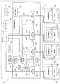
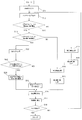
- the block diagram which shows the structure of the battery system of FIG. The flowchart which shows the charging / discharging control method in embodiment concerning this invention.
- the battery system 1 of the present embodiment is a system that supplies power to the mobility 20 and includes a battery pack 10 and a mobility 20 as shown in FIG.
- the mobility 20 is allowed to travel when electric power is supplied from the four battery packs 10 mounted in the space below the seat 20a and the rear wheels (drive wheels) 22 are rotationally driven.
- the mobility 20 is used while replacing the battery pack 10 whose remaining capacity (also referred to as remaining capacity) has decreased due to traveling, spontaneous discharge, or the like with a charged battery pack 10 at a predetermined station 100.
- Battery swap is available.
- the station 100 has an insertion portion 100a into which a plurality of battery packs 10 are inserted.
- the battery pack 10 is disposed in these insertion portions 100a.
- the station 100 is arranged at a plurality of places like a gas station.
- Each of the four battery packs 10 includes a power storage unit 11 and a remaining capacity estimation unit 12 as shown in FIG.
- the four power storage units 11 and the remaining capacity estimation unit 12 will also be described with the reference numerals of the power storage units 11A, 11B, 11C, and 11D and the remaining capacity estimation units 12A, 12B, 12C, and 12D. That is, battery pack 10A includes power storage unit 11A and remaining capacity estimation unit 12A, battery pack 10B includes power storage unit 11B and remaining capacity estimation unit 12B, and battery pack 10C includes power storage unit 11C and remaining capacity estimation unit 12B.
- the battery pack 10D includes a power storage unit 11D and a remaining capacity estimation unit 12D.
- the power storage units 11A, 11B, 11C, and 11D store or discharge power.
- the four power storage units 11A, 11B, 11C, and 11D are electrically connected to the mobility 20 in parallel. Therefore, even when only one of the four battery packs 10 is attached to the mobility 20, it is possible to supply electric power to the motor 21, and the mobility 20 it can.
- the remaining capacity estimation unit 12 estimates the remaining capacity of the power storage unit 11 by measuring current or voltage. That is, the remaining capacity estimation unit 12A estimates the remaining capacity of the power storage unit 11A, the remaining capacity estimation unit 12B estimates the remaining capacity of the power storage unit 11B, the remaining capacity estimation unit 12C estimates the remaining capacity of the power storage unit 11C, The remaining capacity estimation unit 12D estimates the remaining capacity of the power storage unit 11D. The remaining capacity estimation units 12A, 12B, 12C, and 12D transmit the estimated remaining capacities of the power storage units 11A, 11B, 11C, and 11D to the mobility 20.
- the mobility 20 is an electric motorcycle that travels by being supplied with electric power from the four battery packs 10 mounted under the seat 20a. As shown in FIG. 2, the motor 20 and a rear wheel (drive wheel) are provided. 22, a front wheel 23 (see FIG. 1), a throttle 24, a required power calculation unit 25, a display unit 26, and a charge / discharge control device 30.
- the throttle 24 is provided on one side of the handle 20b, and the speed can be adjusted by rotating.
- the required power calculation unit 25 has a sensor that detects the amount of rotation of the throttle, and calculates a required power value from the measured value.
- the charge / discharge control device 30 supplies the power from the battery pack 10 to the motor 21 based on the required power calculated by the required power calculation unit 25.
- the motor 21 receives power supply from the battery pack 10 and transmits a rotational driving force to the axle of the rear wheel 22 serving as a driving wheel.
- the front wheels 23 are steering wheels provided between the front part of the mobility 20 and the road surface, and the direction of travel can be switched by changing the direction in conjunction with the direction of the handle 20b.
- the rear wheel 22 is a drive wheel provided between the rear portion of the mobility 20 on which the battery pack 10 is mounted and the road surface, and is driven to rotate by the motor 21.
- the display unit 26 displays output information of the power storage unit 11.
- the display unit 26 may also serve as a display unit such as the speed of the mobility 20, may be displayed in car navigation, or may be provided alone.
- the charge / discharge control device 30 controls charge / discharge of the four power storage units 11.
- the charge / discharge control device 30 includes a required power input unit 31, a reception unit 32, a connection relationship determination unit 33, connection switching units 34A, 34B, 34C, 34D, a display control unit 38, and a priority setting unit 39. And a used battery determination unit 40.
- the required power input unit 31 receives the required power calculated with the rotation of the throttle 24.
- the receiving unit 32 receives and acquires information on the remaining capacity of the battery packs 10A, 10B, 10C, and 10D.
- the receiving unit 34 acquires the remaining capacities of the respective power storage units 11A, 11B, 11C, and 11D from the remaining capacity estimating units 12A, 12B, 12C, and 12D of the battery packs 10A, 10B, 10C, and 10D. To do.
- the communication between the remaining capacity estimating units 12A, 12B, 12C, 12D and the receiving unit 32 may be wired or wireless.
- connection switching unit 34A switches on / off of the electrical connection between the motor 21 and the power storage unit 11A.
- the connection switching unit 34B switches on / off of the electrical connection between the motor 21 and the power storage unit 11B.
- the connection switching unit 34C switches on / off of the electrical connection between the motor 21 and the power storage unit 11C.
- the connection switching unit 34D switches on / off of the electrical connection between the motor 21 and the power storage unit 11D.
- connection switching units 34A, 34B, 34C, and 34D also perform switching of connection relationships among the power storage units 11A, 11B, 11C, and 11D.
- the motor 21 and the connection switching unit 34A are connected by a motor connection line 35A
- the power storage unit 11A and the connection switching unit 34A are connected by a battery connection line 36A.
- the motor 21 and the connection switching unit 34B are connected by a motor connection line 35B
- the power storage unit 11B and the connection switching unit 34B are connected by a battery connection line 36B.
- the motor 21 and the connection switching unit 34C are connected by a motor connection line 35C
- the power storage unit 11C and the connection switching unit 34C are connected by a battery connection line 36C.
- the motor 21 and the connection switching unit 34D are connected by a motor connection line 35D
- the power storage unit 11D and the connection switching unit 34D are connected by a battery connection line 36D.
- connection switching unit 34A and the connection switching unit 34B are connected by an inter-battery connection line 37A
- connection switching unit 34B and the connection switching unit 34C are connected by an inter-battery connection line 37B
- connection switching unit 34C is connected by an inter-battery connection line 37B
- connection switching unit 34D is connected by an inter-battery connection line 37C.
- the connection switching unit 34A can arbitrarily connect the motor connection line 35A, the battery connection line 36A, and the inter-battery connection line 37A.
- connection switching unit 34B can arbitrarily connect the motor connection line 35B, the battery connection line 36B, the inter-battery connection line 37A, and the inter-battery connection line 37B.
- the connection switching unit 34C can arbitrarily connect the motor connection line 35C, the battery connection line 36C, the inter-battery connection line 37B, and the inter-battery connection line 37C.
- the connection switching unit 34D can arbitrarily connect the motor connection line 35D, the battery connection line 36D, and the inter-battery connection line 37C.
- connection switching unit 34A when charging / discharging between the power storage unit 11A and the power storage unit 11D, the connection switching unit 34A connects the battery connection line 36A and the inter-battery connection line 37A, and the connection switching unit 34B is connected to the inter-battery connection line 37A.
- the inter-battery connection line 37B is connected
- the connection switching unit 34C connects the inter-battery connection line 37B and the inter-battery connection line 37C
- the connection switching unit 34D connects the battery connection line 36D and the inter-battery connection line 37C.
- the connection switching unit 34B can connect the motor connection line 35B and the battery connection line 36B
- connection switching unit 34C can connect the motor connection line 35C and the battery connection line 36C.
- the priority setting unit 39 uses the storage units 11A, 11B, 11C, and 11C when supplying power to the motor 21 based on the remaining capacities of the storage units 11A, 11B, 11C, and 11D acquired by the reception unit 32.
- the priority also referred to as priority
- the used battery determination unit 40 determines the power storage unit 11 to be used when supplying power to the motor 21. To do. For example, when the power storage units 11A, 11B, 11C, and 11D have the highest priority, when the power supply from the two power storage units 11 is necessary to supply the necessary power, the used battery determination unit 40 The power storage unit 11 used by 11A and 11B is determined.
- the connection relation determination unit 33 stores the power storage units 11A, 11B, and 11C according to the required power input to the required power input unit 31 and the remaining capacities of the power storage units 11A, 11B, 11C, and 11D received by the reception unit 32.
- the connection relationship with the 11D motor 21 is determined, and the connection switching units 34A, 34B, 34C, and 34D are controlled. The determination of the connection relationship will be described in detail later.
- the inter-battery connection switching unit 35 switches the connection relationship between the power storage units 11A, 11B, 11C, and 11D.
- the display control unit 38 causes the display unit 26 to display information related to the output from the battery pack 10 based on the remaining capacities of the power storage units 11A, 11B, 11C, and 11D acquired via the reception unit 32.
- the charge / discharge control device 30 and the remaining capacity estimation units 12A, 12B, 12C, and 12D of the present embodiment correspond to an example of the charge / discharge control system, and are illustrated as the charge / discharge control system 50 in FIG. .
- Step S11 corresponds to an example of a necessary power input process.
- Step S12 corresponds to an example of a remaining capacity acquisition process.
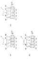
- FIG. 4A is a diagram illustrating the connection of the power storage units 11A, 11B, 11C, and 11D with the motor 21.
- the full charge capacity of each power storage unit 11 is 1.0 kwh, and the rated output is set to 0.5 kw.
- the charge upper limit of the electrical storage part 11 is set to 80% of full charge capacity, for example, and is set to 0.8 kwh.
- the discharge lower limit value of the power storage unit 11 is set to, for example, 20% of the full charge capacity, and is set to 0.2 kwh.
- the charge upper limit value is a value at which the battery is likely to deteriorate when charged
- the discharge lower limit value is a value at which the battery is likely to deteriorate when discharged.
- the remaining capacity of each power storage unit 11 is 0.8 kwh.
- step S13 it is determined whether there are power storage units 11A, 11B, 11C, and 11D whose remaining capacity has reached the first threshold value.
- the first threshold value is larger than a second threshold value, which will be described later, and is set to 0.3 kwh as an example.
- the priority setting unit 39 sets the priority of the power storage unit 11 that is used when supplying necessary power to the motor 21.
- the priority setting unit 39 sets the priority of the power storage unit 11 that is used when supplying necessary power to the motor 21.
- the power storage units 11 that have reached the first threshold do not exist and have the same value, and thus the power storage units 11A, 11B, 11C, which are stored in advance in a memory (not illustrated),
- the priority order is determined in the order of power storage units 11A, 11B, 11C, and 11D. For example, it is assumed that the priorities are determined as No. 1, No. 2, No. 3, No. 4, and No. 4 in the order of the power storage units 11A, 11B, 11C, and 11D.
- step S15 the used battery determination unit 40 determines the power storage unit 11 to be used.
- the connection relationship determination unit 33 performs electrical connection between the power storage units 11 ⁇ / b> A, 11 ⁇ / b> B, 11 ⁇ / b> C, 11 ⁇ / b> D and the motor 21 based on the power storage unit 11 determined to be used in step S ⁇ b> 15. Determine the relationship.
- Step S16 corresponds to an example of a connection relationship determination step.
- connection switching units 34A, 34B, 34C, and 34D are determined so that the unit 11D is not connected to the motor 21. Further, for example, when the required power input to the required power input unit 31 is 0.5 kw or less, the connection switching is performed so that only the power storage unit 11A is connected to the motor 21 as illustrated in FIG. Switching states of the units 34A, 34B, 34C, and 34D are determined.
- Step S17 corresponds to an example of a connection switching process. Electric power is supplied until the request for electric power is stopped by returning the throttle 24, or until the required electric power is changed by changing the opening of the throttle 24 (step S18).
- step S13 When there is a battery whose remaining capacity is less than or equal to the first threshold and greater than or equal to the second threshold)
- step S19 When the remaining capacity of the power storage unit 11 selected in step S13 is not more than the second threshold value is not less than the second threshold value (step S19), the control moves to step S20.
- the priority setting part 39 sets the priority of the four electrical storage parts 11 so that the priority of the electrical storage part 11 whose remaining capacity is below a 1st threshold value and more than a 2nd threshold value may be made low.
- step S ⁇ b> 21 the used battery determination unit 40 determines the power storage unit 11 to be used to supply the requested power based on the changed priority order.
- step S ⁇ b> 16 based on the power storage unit 11 determined to be used, the connection relationship determination unit 33 determines the electrical connection relationship between the power storage units 11 ⁇ / b> A, 11 ⁇ / b> B, 11 ⁇ / b> C, 11 ⁇ / b> D and the motor 21. decide.
- step S20 priority setting unit 39 changes the priority of power storage units 11A, 11B, 11C, and 11D.
- the priority setting unit 39 sets the priority to No. 1, No. 2, No. 3, No. 4, and No. 4 in the order of the power storage units 11B, 11C, 11D, and 11A.
- the electrical storage part 11 with the high priority of the last time it is preferable to make it a high priority also in the case of a change. That is, it is preferable to increase the priority in ascending order of the remaining capacity except for the power storage unit 11 that has reached the first threshold. This is because using the power storage unit 11 in order to reach the first threshold can increase the total remaining capacity more efficiently with a small number of replacements when the battery pack is replaced in the station 100.
- the used battery determination part 40 determines the electrical storage part 11 used in order to supply the requested
- the power storage unit 11B When the required power is 0.5 kw or less, the power storage unit 11B is used to supply power to the motor 21. When the required power is greater than 1.0 kW, the power storage units 11B, 11C, and 11D are used to supply power to the motor 21. Further, when the required power is larger than 1.5 kw, the power storage units 11A, 11B, 11C, and 11D are used to supply power to the motor 21. As described above, when the control is performed so that the remaining capacity of the first threshold value remains in the power storage unit 11 as much as possible, the opening degree of the throttle 24 is changed and all the power storage units 11 must be used. Moreover, since all the electrical storage parts 11 can output rated electric power, it can respond to a user's electric power request
- step S19 when it is estimated that the remaining capacity of the power storage unit 11 has reached the second threshold value (discharge lower limit, 0.2 kwh), in step S22, the priority setting unit 39
- the power storage unit 11 that has reached the threshold is disabled and the priority of the power storage unit 11 is set.
- the power storage unit 11A when the remaining capacity of the power storage unit 11A has reached the second threshold, the power storage unit 11A is made unusable and priority is set for the other power storage units 11B, 11C, and 11D. .
- the power storage units 11B, 11C, 11D, and 11A are set in the order of No. 1, No. 2, No. 3, and No. 4, when the power storage unit 11A reaches the second threshold,
- the priority is set as No. 1, No. 2, No. 3 in the order of 11C and 11D.
- the used battery determination unit 40 determines the power storage unit 11 to be used for supplying the requested power based on the priority, but uses the power storage unit 11 equal to or lower than the second threshold in step S23. Otherwise, it is determined whether or not the required power cannot be supplied. For example, in the case illustrated in FIG. 6A, if 1.0 kW of power is requested when the remaining capacity of the power storage unit 11A reaches the second threshold, the power storage unit 11A may not be connected to the motor 21. As shown in FIG. 6A, the required output can be satisfied by connecting the other power storage units 11 ⁇ / b> B and 11 ⁇ / b> C to the motor 21.
- the connection relationship determination unit 33 determines whether or not the power storage unit 11 that has reached the second threshold can be charged from the other power storage unit 11 (step S24).
- the connection relationship determination unit 33 determines whether or not the power storage unit 11 that has reached the second threshold can be charged from the other power storage unit 11 (step S24).
- the power storage units 11 ⁇ / b> B and 11 ⁇ / b> C supply power to the motor 21, but the power storage unit 11 ⁇ / b> D does not supply power to the motor 21.
- the remaining capacity of the power storage unit 11D is 0.8 kwh, even if 0.1 kwh is supplied to the power storage unit 11A, it does not reach the first threshold (0.3 kwh).
- connection relationship determination unit 33 determines that the power storage unit 11 that has reached the second threshold can be charged from the other power storage unit 11.
- the connection relationship determination unit 33 considers charging / discharging between the power storage units 11 and power supply to the motor 21, and performs electrical connection between the power storage units 11 ⁇ / b> A, 11 ⁇ / b> B, 11 ⁇ / b> C, 11 ⁇ / b> D and the motor 21.
- the appropriate connection relationship is between the battery connection line 36A and the inter-battery connection line 37A, or between the battery connection line 37A and the battery.
- connection lines 37B Between connection lines 37B, between battery connection line 37B and battery connection line 37C, between battery connection line 37C and battery connection line 36D, and between battery connection line 36B and motor connection line 35B
- the battery connection line 36C and the motor connection line 35C are determined to be connected.
- the connection if there is a power storage unit 11 that is equal to or less than the first threshold and has a larger remaining capacity than the second threshold, the priority of the power storage unit 11 is lowered.
- the display control unit 38 displays a notification that the required power cannot be supplied on the display unit 26 (Ste S25). For example, this is a case where 2.0 kW of power is required when the remaining capacity of the power storage unit 11A reaches the second threshold. In this case, the required output cannot be satisfied unless the power storage unit 11A is used. For this reason, a notification that the required power cannot be supplied is displayed on the display unit 26. In addition, this notification may be notified to be displayed on the liquid crystal screen, or may be notified to the user by turning on an LED lamp, for example.
- the charging / discharging control device 30 of the present embodiment is a charging / discharging control device that controls charging / discharging of a plurality of power storage units 11 that can be attached to and detached from the mobility 20 and can be connected in parallel, and includes a necessary power input unit 31 and a receiving unit. 32 and a priority setting unit 39.
- the required power input unit 31 receives a request for power to be supplied to the motor 21 of the mobility 20.
- the receiving unit 32 acquires the remaining capacity of each power storage unit 11.
- the priority setting unit 39 uses the plurality of power storage units 11A, 11B, 11C, and 11D when supplying the power input to the required power input unit 31 based on the remaining capacity acquired by the reception unit 32. Set the priority.
- the remaining capacity of the plurality of power storage units 11 can be obtained by using a predetermined power storage unit 11 with priority. Can be biased evenly. That is, the remaining capacity of the power storage unit 11 (for example, the power storage units 11A and 11B in FIG. 5B) used preferentially can be reduced, and the power storage units 11C and 11D in the other power storage units 11 (FIG. 5B). ) Can be increased. For this reason, it is possible to efficiently replace the power storage unit 11 held by the mobility 20 by exchanging the power storage units 11 (power storage units 11A and 11B in FIG. 5B) having a small remaining capacity without replacing all the power storage units 11.
- the total remaining capacity can be increased.
- the battery pack 10A of the power storage unit 11A and the battery pack 10B of the power storage unit 11B are replaced with a charged battery pack 10 (0.8 kwh), thereby reducing the total remaining capacity to 2. It can be increased from 1 kwh to 3.0 kwh.
- the total remaining capacity of the battery pack 10 held by the power consumer can be increased with a small number of replacements, it is possible to reduce the trouble of replacing the battery pack 10.
- the remaining capacity of the power storage unit 11 used preferentially decreases (for example, 0.3 kwh)
- the remaining capacity of the power storage unit 11 becomes the discharge lower limit value by using other power storage units 11 with priority. Can be prevented.
- the rated output can be performed from all the power storage units 11, so that the user's power request can be met. it can.
- it is possible to adjust the remaining capacity of the battery so as to reduce the labor for battery replacement in the station 100 and to respond to the user's power demand.
- the charge / discharge control device 30 further includes a used battery determination unit 40 and a connection relationship determination unit 33.
- the used battery determination unit 40 uses one or more power storage units 11 to be used among the plurality of power storage units 11. (In FIGS. 4B and 4C, the power storage unit 11A) is determined.
- the connection relationship determining unit 33 is an electrical connection relationship between the plurality of power storage units 11 and the motor 21 of the mobility 20 so as to supply power to the motor 21 from the power storage unit 11 whose use has been determined by the used battery determination unit 40. To decide. Thus, by setting the electrical connection relationship, the predetermined power storage unit 11 can be preferentially used even if the required power is changed.
- the priority setting unit 39 is based on the remaining capacity acquired by the receiving unit 32, and the power storage unit 11 (power storage unit 11A in FIG.
- the priority of the power storage unit 11 is lowered and the other power storage units 11 (in FIG. 5, the power storage units 11B, 11C, 11D) is set to a high priority.
- the remaining capacity of the power storage unit 11 that is used preferentially reaches a first threshold value (for example, 0.3 kwh)
- the remaining power storage unit 11 is preferentially used, so that the remaining power of the power storage unit 11 is preferentially used.
- the capacity can be kept at the first threshold as much as possible. For this reason, even when the maximum output power based on the number of power storage units 11 is requested, the rated output can be performed from all the power storage units 11, so that the user's power request can be met. it can.
- the priority setting unit 39 includes, among the plurality of power storage units 11, the power storage unit 11 having a remaining capacity that is less than or equal to the second threshold value (see FIG. 6A). Then, the power storage unit 11A) is disabled. Thereby, use of the electrical storage part 11 whose remaining capacity is below a 2nd threshold value can be prevented.
- the priority setting unit 39 is configured such that the plurality of power storage units 11 are sequentially set to the first threshold value (in FIG. 5), as shown in FIGS. For example, the priority is set to reach 0.3 kwh). In this way, by controlling the plurality of power storage units 11 to sequentially reach the first threshold one by one, the power storage unit 11 (the power storage unit 11A in FIG. 5B) whose remaining capacity has reached the first threshold or By exchanging the power storage unit 11 (the power storage unit 11B in FIG. 5B) with a remaining capacity close to the first threshold at the station 100, the total remaining capacity of the power storage unit 11 held by the mobility 20 can be increased efficiently.
- the first threshold value is a remaining capacity capable of supplying the rated power (for example, 0.5 kW) of the power storage unit 11. Thereby, the rated power can be output from the power storage unit 11 whose remaining capacity has reached the first threshold value.
- the connection relationship determining unit 33 is configured such that the remaining capacity of the power storage unit 11 is less than a first threshold value (for example, 0.3 kwh) (in FIG. 6, 0.2 kwh). ), The power storage unit 11 (FIG. 6B) whose remaining capacity has reached the second threshold value from another power storage unit 11 (power storage unit 11D in FIG.
- the electrical connection relationship is determined so as to supply power to the power storage unit 11A).
- the power storage unit 11 is supplemented with electric power from the other power storage unit 11.
- the deterioration of each power storage unit 11 can be prevented by setting the second threshold value to, for example, the discharge lower limit value.
- the connection relationship determining unit 33 determines that the remaining capacity of the power storage unit 11 whose remaining capacity has reached the second threshold (0.2 kwh in FIG. 6) is the first threshold (for example, The electrical connection relationship is determined so that electric power is supplied from the other power storage unit 11 until 0.3 kwh) is reached.
- the remaining capacity of the power storage unit 11 reaches the second threshold value
- power is supplemented from the other power storage units 11 until the remaining capacity of the power storage unit 11 reaches the first threshold value.
- the charge / discharge control device 30 further includes a display control unit 38.
- the priority setting unit 39 disables the power storage unit 11 (the power storage unit 11 ⁇ / b> A in FIG. 6A) having a remaining capacity less than or equal to the second threshold value among the plurality of power storage units 11.
- the display control unit 38 determines the power storage unit 11 to be used by the used battery determination unit 40 and cannot use the unusable power storage unit 11 to supply the required power, the display control unit 38 cannot supply the required power.
- the mobility 20 is an electric motorcycle or an electric bicycle.
- the mobility 20 mobility including an electric motorcycle and an electric bicycle is used.
- the battery pack 10 of the power storage unit 11 with a small remaining capacity can be efficiently replaced with the charged battery pack 10.
- the charge / discharge control system 50 of this embodiment includes a remaining capacity estimation unit 12, a required power input unit 31, and a priority setting unit 39.
- the remaining capacity estimation unit 12 estimates the remaining capacity of the power storage unit 11 that can be attached to and detached from the mobility 20 and can be connected in parallel.
- the required power input unit 31 receives a request for power to be supplied to the motor 21 of the mobility 20.
- the priority setting unit 39 uses a plurality of power storage units 11A, 11B, 11C, and 11D when supplying power input to the required power input unit 31 based on the remaining capacity acquired by the remaining capacity estimation unit 12. Set usage priority.
- the charge / discharge control system can acquire the remaining capacity of each of the plurality of power storage units 11 and control the remaining capacity. For this reason, while adjusting the remaining capacity of the electrical storage part 11 so that the effort of replacement
- the charge / discharge control method is a charge / discharge control method for controlling charge / discharge of a plurality of power storage units 11 that can be attached to and detached from the mobility 20 and can be connected in parallel.
- Step S11 an example of a necessary power input process
- Step S12 an example of a remaining capacity acquisition process
- Step S14 an example of a priority setting process
- step S11 a request for power to be supplied to the motor 21 of the mobility 20 is input.
- step S12 the remaining capacity of each power storage unit 11 is acquired.
- Step S14 sets the priority of use of the plurality of power storage units 11 when supplying the electric power input in step S11 based on the remaining capacity estimated in step S12.
- the remaining capacity of the plurality of power storage units 11 can be obtained by using a predetermined power storage unit 11 with priority. Can be biased evenly. That is, the remaining capacity of the power storage unit 11 used preferentially can be reduced, and the remaining capacity of other power storage units 11 can be increased. For this reason, it is possible to efficiently increase the total remaining capacity of the power storage units 11 held by the power consumer by exchanging the power storage units 11 with a small remaining capacity without replacing all the power storage units 11. Thus, since the total remaining capacity of the power storage unit 11 possessed by the mobility 20 can be increased with a small number of replacements, the labor for replacing the battery pack 10 can be reduced.
- the remaining capacity of the power storage unit 11 used preferentially decreases the remaining capacity of the power storage unit 11 can be prevented from reaching the discharge lower limit value by using another power storage unit 11 with priority. . For this reason, even when the maximum output based on the number of the power storage units 11 is requested, the rated output can be performed from all the power storage units 11, so that the user's power request can be met.
- the second threshold value is set to the discharge lower limit value, but is not limited to the discharge lower limit value.
- the rated output from each power storage unit 11 is secured by setting the second threshold value to the lower limit value that can ensure the rated output. it can. Thereby, it can control so that all the some electrical storage parts 11 can output rated power as long as possible.
- the power storage unit 11 that has reached the second threshold value is controlled to be charged from another power storage unit 11 if possible. Control may be performed so that the power storage unit 11 having reached the two thresholds is not simply used.
- control is performed so that the remaining capacity of the power storage unit 11 is between the discharge lower limit value and the charge upper limit value, but the lower limit value is set to 0 (zero) and the upper limit value is 100 ( Full charge capacity) may be set, and control may be performed during that time.
- the remaining capacity of all the power storage units 11 is connected by connecting all the power storage units 11 to the motor 21. May be reduced evenly.
- the remaining capacity estimation unit 12 is provided in the battery pack 10, and the charge / discharge control device 30 acquires the remaining capacity of the power storage unit 11 via the receiving unit 32 as an example of the remaining capacity acquisition unit.
- the remaining capacity estimation unit 12 may be provided in the charge / discharge control device 30 instead of the battery pack 10.
- the remaining capacity estimation unit 12 provided in the charge / discharge control device 30 estimates each remaining capacity of the power storage units 11 of the plurality of battery packs 10.
- this remaining capacity estimation part 12 respond
- the priority setting unit 39 determines the priorities of the power storage units 11A, 11B, 11C, and 11D based on the priority order of the power storage units 11 set in advance in the memory. It is not limited to. (F-1) In the priority setting unit 39, the priorities of the plurality of power storage units 11 may be determined in the order set by the user. For example, the user can preferentially use the battery pack 10 that has not been replaced for a long period of time.
- the priority setting unit 39 may determine the priorities of the power storage units 11A, 11B, 11C, and 11D based on the remaining capacities of the power storage units 11A, 11B, 11C, and 11D acquired by the reception unit 32. For example, it may be preferentially used in the order of the remaining capacity. Further, for example, the remaining capacity may be preferentially used in the order from the smallest remaining capacity, and the remaining capacity may be preferentially used from the central power storage unit 11. In any case, control may be performed so that the remaining capacity reaches the first threshold in order from the power storage unit 11 having the highest priority.
- the priority setting part 39 may determine the priority of electrical storage part 11A, 11B, 11C, 11D based on the frequency
- the description has been given using, for example, an electric motorcycle as an electric power consumer.
- the power consumer may be a power tool such as a drill.
- the charging / discharging control device, charging / discharging control system, and charging / discharging control method of the present invention have the effect of adjusting the remaining capacity of the battery so as to reduce the labor of battery replacement and responding to the user's power demand. And is widely applicable to mobility driven by replaceable batteries.
Landscapes
- Engineering & Computer Science (AREA)
- Power Engineering (AREA)
- Transportation (AREA)
- Mechanical Engineering (AREA)
- Life Sciences & Earth Sciences (AREA)
- Sustainable Development (AREA)
- Sustainable Energy (AREA)
- Chemical & Material Sciences (AREA)
- Combustion & Propulsion (AREA)
- Charge And Discharge Circuits For Batteries Or The Like (AREA)
- Electric Propulsion And Braking For Vehicles (AREA)
- Secondary Cells (AREA)
Abstract
充放電制御装置(30)は、モビリティ(20)に着脱可能且つ並列接続可能な複数の蓄電部(11)の充放電を制御する充放電制御装置であって、必要電力入力部(31)と、受信部(32)と、優先度設定部(39)と、を備えている。必要電力入力部(31)は、モビリティ(20)のモータ(21)に供給する電力の要求が入力される。受信部(32)は、各々の蓄電部(11)の残容量を取得する。優先度設定部(39)は、受信部(32)によって取得された残容量に基づいて、必要電力入力部(31)に入力された電力を供給する際の、複数の蓄電部(11A、11B、11C、11D)の使用の優先度を設定する。
Description
本発明は、バッテリの充放電の制御を行う充放電制御装置、充放電制御システムおよび充放電制御方法に関する。
従来、並列接続可能な複数のバッテリを備えた車両が提案されている(例えば、特許文献1参照。)。
特許文献1に示す車両は、車両の幅方向に間隔を隔てて複数のバッテリが配置可能に構成されている。そして、走行距離に応じて使用者によってバッテリの取り外し又は追加が行われる。
特許文献1に示す車両は、車両の幅方向に間隔を隔てて複数のバッテリが配置可能に構成されている。そして、走行距離に応じて使用者によってバッテリの取り外し又は追加が行われる。
一方、近年、電動自動二輪車や電動自転車等のモビリティに搭載されたバッテリを、充電済みのバッテリを保有するステーションにおいて交換しながら利用するシステムが構築されている。
しかしながら、特許文献1に示すような並列接続可能な複数のバッテリを用いた場合、以下のような問題点が発生することが考えられる。
すなわち、図7(a)に示すように負荷1001(例えば、モータ)に対して並列接続された複数のバッテリ1000を備えたモビリティでは、走行に従って通常は均等に容量が減少する(図7(a)では、残容量は0.4kwhである)。このため、ステーションにおいて全てのバッテリを交換する必要があり、手間がかかることが考えられる。
すなわち、図7(a)に示すように負荷1001(例えば、モータ)に対して並列接続された複数のバッテリ1000を備えたモビリティでは、走行に従って通常は均等に容量が減少する(図7(a)では、残容量は0.4kwhである)。このため、ステーションにおいて全てのバッテリを交換する必要があり、手間がかかることが考えられる。
一方、ステーションにおけるバッテリの交換本数を減らすために、図7(b)に示すようにバッテリ1000を1つずつ順に負荷1001に対して接続可能な構成も考えられる。このような構成では、例えば各バッテリ1000の定格出力を0.5kwとした場合、1つずつしかバッテリ1000を負荷1001に接続できないため、急加速の際等に0.5kwよりも大きい電力の要求があったとしても、その要求に応えることができない。
本発明の課題は、バッテリ交換の手間を軽減するようにバッテリの残容量の調整を行うとともに、ユーザの電力要求に対応することが可能な充放電制御装置、充放電制御システム、および充放電制御方法を提供することにある。
第1の発明に係る充放電制御装置は、電力消費体に着脱可能且つ並列接続可能な複数のバッテリの充放電を制御する充放電制御装置であって、必要電力入力部と、残容量取得部と、優先度設定部と、を備えている。必要電力入力部は、電力消費体の駆動源に供給する電力の要求が入力される。残容量取得部は、各々のバッテリの残容量を取得する。優先度決定部は、残容量取得部によって取得された残容量に基づいて、必要電力入力部に入力された電力を供給する際の、複数のバッテリの使用の優先度を設定する。
要求される電力の大きさによって、複数のバッテリのうち使用されるバッテリの数は異なるが、所定のバッテリを優先的に使用することによって、複数のバッテリの残容量を均等に減らさず偏らせることができる。すなわち、優先的に使用するバッテリの残容量を少なくでき、他のバッテリの残容量を多くできる。このため、全てのバッテリを交換せず、残容量の少ないバッテリを交換することによって、効率よく電力消費体の保有するバッテリの総残容量を増加させることができる。このように、少ない交換数で電力消費体の保有するバッテリの総残容量を増加できるため、バッテリ交換の手間を軽減できる。
また、優先的に使用されるバッテリの残容量が減少すると、他のバッテリを優先的に使用することによって、バッテリの残容量がゼロまたは放電下限値に達することを防ぐことが出来る。このため、バッテリの数に基づいた最大出力が要求された場合であっても、全てのバッテリから定格の出力を行うことができるため、ユーザの電力要求に対応することができる。
以上のように、ステーションにおけるバッテリ交換の手間を軽減するようにバッテリの残容量の調整を行うとともに、ユーザの電力要求に対応することが出来る。
なお、電力消費体としては、例えば、電動自動二輪車、電動自転車、電動アシスト自転車、電動一輪車、電気自動車(EV)、PHV(Plug-in Hybrid Vehicle)等のモビリティ等が含まれる。また、電力消費体として、電動ドリル等の電動工具も含まれる。
なお、電力消費体としては、例えば、電動自動二輪車、電動自転車、電動アシスト自転車、電動一輪車、電気自動車(EV)、PHV(Plug-in Hybrid Vehicle)等のモビリティ等が含まれる。また、電力消費体として、電動ドリル等の電動工具も含まれる。
第2の発明に係る充放電制御装置は、第1の発明に係る充放電制御装置であって、使用バッテリ決定部と、接続関係決定部と、を更に備える。使用バッテリ決定部は、必要電力入力部に入力された電力および優先度設定部によって設定された優先度に基づいて、複数のバッテリのうち使用する1つまたは複数のバッテリを決定する。接続関係決定部は、使用バッテリ決定部によって使用が決定されたバッテリから駆動源に電力を供給するように、複数のバッテリと電力消費体の駆動源との電気的な接続関係を決定する。
このように、電気的接続関係を設定することによって、要求電力が変更されても所定のバッテリを優先的に使用することが出来る。
このように、電気的接続関係を設定することによって、要求電力が変更されても所定のバッテリを優先的に使用することが出来る。
第3の発明に係る充放電制御装置は、第1の発明に係る充放電制御装置であって、優先度設定部は、ユーザによって設定された順に複数のバッテリの優先度を設定する。
これにより、ユーザによって設定された順にバッテリを使用することができる。
これにより、ユーザによって設定された順にバッテリを使用することができる。
第4の発明に係る充放電制御装置は、第1の発明に係る充放電制御装置であって、優先度設定部は、使用回数に基づいて、複数のバッテリの優先度を設定する。
これにより、例えば、使用回数が少ない順または使用回数が多い順にバッテリを使用することができる。
これにより、例えば、使用回数が少ない順または使用回数が多い順にバッテリを使用することができる。
第5の発明に係る充放電制御装置は、第1の発明に係る充放電制御装置であって、優先度設定部は、残容量取得部によって取得された残容量に基づいて、優先度が高いバッテリの残容量が第1閾値に達したことが推定された場合、バッテリの優先度を低くして他のバッテリの優先度を高く設定する。
これによって、優先的に使用されるバッテリの残容量が第1閾値に達すると、他のバッテリを優先的に使用することによって、バッテリの残容量を第1閾値に保つことができる。
このため、バッテリの数に基づいた最大出力が要求された場合であっても、全てのバッテリから定格の出力を行うことができる。
これによって、優先的に使用されるバッテリの残容量が第1閾値に達すると、他のバッテリを優先的に使用することによって、バッテリの残容量を第1閾値に保つことができる。
このため、バッテリの数に基づいた最大出力が要求された場合であっても、全てのバッテリから定格の出力を行うことができる。
第6の発明に係る充放電制御装置は、第5の発明に係る充放電制御装置であって、優先度設定部は、複数のバッテリのうち、残容量が第1閾値よりも少ない第2閾値以下のバッテリを使用不可とする。
これにより、残容量が第2閾値以下のバッテリの使用を防ぐことができる。
第7の発明に係る充放電制御装置は、第5の発明に係る充放電制御装置であって、優先度設定部は、複数のバッテリが1つずつ順に第1閾値に達するように、優先度を設定する。
このように、複数のバッテリが1つずつ順に第1閾値に達するように制御することによって、残容量が第1閾値に達したバッテリまたは残容量が第1閾値に近いバッテリをステーションで交換することによって効率よく電力消費体の保有するバッテリの総残容量を増加できる。
これにより、残容量が第2閾値以下のバッテリの使用を防ぐことができる。
第7の発明に係る充放電制御装置は、第5の発明に係る充放電制御装置であって、優先度設定部は、複数のバッテリが1つずつ順に第1閾値に達するように、優先度を設定する。
このように、複数のバッテリが1つずつ順に第1閾値に達するように制御することによって、残容量が第1閾値に達したバッテリまたは残容量が第1閾値に近いバッテリをステーションで交換することによって効率よく電力消費体の保有するバッテリの総残容量を増加できる。
第8の発明に係る充放電制御装置は、第5から第7のいずれかの発明に係る充放電制御装置であって、第1閾値は、バッテリの定格電力を供給可能な残容量である。
これにより、残容量が第1閾値に達したバッテリから定格電力を出力できる。
これにより、残容量が第1閾値に達したバッテリから定格電力を出力できる。
第9の発明に係る充放電制御装置は、第2の発明に係る充放電制御装置であって、優先度設定部は、残容量取得部によって取得された残容量に基づいて、優先度が高いバッテリの残容量が第1閾値に達したことが推定された場合、バッテリの優先度を低くして他のバッテリの優先度を高く設定する。接続関係決定部は、バッテリの残容量が第1閾値よりも少ない第2閾値に達した場合、残容量が第1閾値よりも多い他のバッテリから、残容量が第2閾値に達したバッテリに電力を供給するように、電気的な接続関係を決定する。
このように、バッテリの残容量が第2閾値に達すると、そのバッテリに他のバッテリから電力が補充される。第2閾値を、例えば、定格出力が確保できる下限値に設定することにより、各バッテリからの定格出力を担保できる。
また、第2閾値を、例えば、放電下限値に設定することにより、各バッテリの劣化を妨げることができる。
また、第2閾値を、例えば、放電下限値に設定することにより、各バッテリの劣化を妨げることができる。
第10の発明に係る充放電制御装置は、第9の発明に係る充放電制御装置であって、接続関係決定部は、残容量が第2閾値に達したバッテリの残容量が第1閾値に達するまで、他のバッテリから電力を供給するように、電気的な接続関係を決定する。
このように、バッテリの残容量が第2閾値に達すると、そのバッテリの残容量が第1閾値に達するまで他のバッテリから電力が補充される。これにより、出来るだけ長い期間ユーザの要求出力に応えることが出来る。
このように、バッテリの残容量が第2閾値に達すると、そのバッテリの残容量が第1閾値に達するまで他のバッテリから電力が補充される。これにより、出来るだけ長い期間ユーザの要求出力に応えることが出来る。
第11の発明に係る充放電制御装置は、第2の発明に係る充放電制御装置であって、表示制御部を更に備える。優先度設定部は、残容量取得部によって取得された残容量に基づいて、優先度が高いバッテリの残容量が第1閾値に達したことが推定された場合、バッテリの優先度を低くして他のバッテリの優先度を高く設定する。優先度設定部は、複数のバッテリのうち、残容量が第1閾値よりも少ない第2閾値以下のバッテリを使用不可とする。表示制御部は、使用バッテリ決定部が使用するバッテリを決定する際に、使用不可のバッテリを使用しないと要求される電力を供給できないとき、要求される電力を供給できない旨の通知を電力消費体の表示部に表示させる。
これにより電力消費体を操作するユーザに要求電力を供給できないことを知らせることができる。すなわち、ユーザは、例えば急加速を行っても速度を急には早く出来ないことを認識できる。
第12の発明に係る充放電制御装置は、第6、9、10および11のいずれかの発明に係る充放電制御装置であって、第2閾値は、放電下限値またはバッテリの定格電力を供給できなくなる残容量である。
第2閾値をバッテリの定格電力を供給できなくなる残容量とすることにより、複数のバッテリの全てが出来るだけ長く定格電力を出力できるように制御を行うことができる。
また、第2閾値を放電下限値とすることにより、バッテリの劣化を抑制することができる。
第2閾値をバッテリの定格電力を供給できなくなる残容量とすることにより、複数のバッテリの全てが出来るだけ長く定格電力を出力できるように制御を行うことができる。
また、第2閾値を放電下限値とすることにより、バッテリの劣化を抑制することができる。
第13の発明に係る充放電制御装置は、第1の発明に係る充放電制御装置であって、電力消費体は、電動自動二輪車、電動アシスト自転車、電動自転車、あるいは電動工具である。
ここでは、電力消費体として、電動自動二輪車、電動自転車を含むモビリティを用いている。
これにより、ステーションにおいて、残容量が少ないバッテリを充電済みのバッテリと効率よく交換できる。また、スロットルの開度または踏み込み量などによるユーザの電力要求に対応することが可能となる。
なお、電力消費体としては、電動ドリル等の電動工具も含まれる。
ここでは、電力消費体として、電動自動二輪車、電動自転車を含むモビリティを用いている。
これにより、ステーションにおいて、残容量が少ないバッテリを充電済みのバッテリと効率よく交換できる。また、スロットルの開度または踏み込み量などによるユーザの電力要求に対応することが可能となる。
なお、電力消費体としては、電動ドリル等の電動工具も含まれる。
第14の発明に係る充放電制御システムは、残容量推定部と、必要電力入力部と、優先度設定部と、を備える。残容量推定部は、電力消費体に着脱可能且つ並列接続可能な複数のバッテリの残容量を推定する。必要電量入力部は、電力消費体の駆動源に供給する電力の要求が入力される。優先度設定部は、残容量推定部によって推定された残容量に基づいて、必要電力入力部に入力された電力を供給する際の、複数のバッテリの使用の優先度を設定する。
これにより、充放電制御装置は、複数のバッテリの各々の残容量を取得し、残容量の制御を行うことができる。
このため、ステーションにおけるバッテリ交換の手間を軽減するようにバッテリの残容量の調整を行うとともに、ユーザの電力要求に対応することが出来る。
これにより、充放電制御装置は、複数のバッテリの各々の残容量を取得し、残容量の制御を行うことができる。
このため、ステーションにおけるバッテリ交換の手間を軽減するようにバッテリの残容量の調整を行うとともに、ユーザの電力要求に対応することが出来る。
第15の発明に係る充放電制御方法は、電力消費体に着脱可能且つ並列接続可能な複数のバッテリの充放電を制御する充放電制御方法であって、必要電力入力工程と、残容量取得工程と、優先度設定工程と、を備える。必要電力入力工程は、電力消費体の駆動源に供給する電力の要求が入力される。残容量取得工程は、各々のバッテリの残容量を取得する。優先度設定工程は、残容量取得工程によって取得された残容量に基づいて、必要電力入力工程において入力された電力を供給する際の、複数のバッテリの使用の優先度を設定する。
要求される電力の大きさによって、複数のバッテリのうち使用されるバッテリの数は異なるが、所定のバッテリを優先的に使用することによって、複数のバッテリの残容量を均等に減らさず偏らせることができる。すなわち、優先的に使用するバッテリの残容量を少なくでき、他のバッテリの残容量を多くできる。このため、全てのバッテリを交換せず、残容量の少ないバッテリを交換することによって、効率よく電力消費体の保有するバッテリの総残容量を増加させることができる。このように、少ない交換数で電力消費体の保有するバッテリの総残容量を増加できるため、バッテリ交換の手間を軽減できる。
また、優先的に使用されるバッテリの残容量が減少すると、他のバッテリを優先的に使用することによって、バッテリの残容量がゼロまたは放電下限値に達することを防ぐことが出来る。このため、バッテリの数に基づいた最大出力が必要な電力が要求された場合であっても、全てのバッテリから定格の出力を行うことができるため、ユーザの電力要求に対応することができる。
以上のように、ステーションにおけるバッテリ交換の手間を軽減するようにバッテリの残容量の調整を行うとともに、ユーザの電力要求に対応することが出来る。
以上のように、ステーションにおけるバッテリ交換の手間を軽減するようにバッテリの残容量の調整を行うとともに、ユーザの電力要求に対応することが出来る。
(発明の効果)
本発明の充放電制御装置、充放電制御システムおよび充放電制御方法によればバッテリ交換の手間を軽減するようにバッテリの残容量の調整を行うとともに、ユーザの電力要求に対応することが出来る。
本発明の充放電制御装置、充放電制御システムおよび充放電制御方法によればバッテリ交換の手間を軽減するようにバッテリの残容量の調整を行うとともに、ユーザの電力要求に対応することが出来る。
以下に、本発明の実施の形態に係るバッテリシステム、充放電制御装置および充放電制御方法について、図面を参照しながら説明する。
<1.構成>
(1-1.バッテリシステム1)
本実施形態のバッテリシステム1は、モビリティ20に対して電力供給を行うシステムであって、図1に示すように、バッテリパック10と、モビリティ20と、を備えている。
<1.構成>
(1-1.バッテリシステム1)
本実施形態のバッテリシステム1は、モビリティ20に対して電力供給を行うシステムであって、図1に示すように、バッテリパック10と、モビリティ20と、を備えている。
バッテリパック10は、図1に示すように、電動自動二輪車等のモビリティ20に4本搭載されている。
モビリティ20は、シート20aの下の空間に搭載された4本のバッテリパック10から電力を供給されて、後輪(駆動輪)22が回転駆動されることで、走行可能となる。
また、モビリティ20は、走行や自然放電等によって残容量(残存容量ともいえる)が少なくなったバッテリパック10を、所定のステーション100において、充電済みのバッテリパック10と交換しながら使用される、いわゆるバッテリスワップを利用可能である。ステーション100は、図1に示すように複数のバッテリパック10が挿入される挿入部100aを有している。これらの挿入部100aにバッテリパック10が配置されている。なお、ステーション100は、ガソリンスタンドのように複数個所に配置されている。
モビリティ20は、シート20aの下の空間に搭載された4本のバッテリパック10から電力を供給されて、後輪(駆動輪)22が回転駆動されることで、走行可能となる。
また、モビリティ20は、走行や自然放電等によって残容量(残存容量ともいえる)が少なくなったバッテリパック10を、所定のステーション100において、充電済みのバッテリパック10と交換しながら使用される、いわゆるバッテリスワップを利用可能である。ステーション100は、図1に示すように複数のバッテリパック10が挿入される挿入部100aを有している。これらの挿入部100aにバッテリパック10が配置されている。なお、ステーション100は、ガソリンスタンドのように複数個所に配置されている。
(1-2.バッテリパック10)
本実施形態のバッテリパック10は、モビリティ20に対して電力を供給するために、モビリティ20に対して交換可能な状態で4本搭載されている。ここで、4本のバッテリパック10を区別する際には、バッテリパック10A、10B、10C、10Dと符号を付して説明する。
本実施形態のバッテリパック10は、モビリティ20に対して電力を供給するために、モビリティ20に対して交換可能な状態で4本搭載されている。ここで、4本のバッテリパック10を区別する際には、バッテリパック10A、10B、10C、10Dと符号を付して説明する。
4本のバッテリパック10は、図2に示すように、それぞれ蓄電部11と残容量推定部12とを有する。4つの蓄電部11と残容量推定部12についても、区別する際には、蓄電部11A、11B、11C、11D、残容量推定部12A、12B、12C、12Dと符号を付して説明する。すなわち、バッテリパック10Aは、蓄電部11Aと残容量推定部12Aとを有し、バッテリパック10Bは、蓄電部11Bと残容量推定部12Bとを有し、バッテリパック10Cは、蓄電部11Cと残容量推定部12Cとを有し、バッテリパック10Dは、蓄電部11Dと残容量推定部12Dとを有する。
蓄電部11A、11B、11C、11Dは、電力を蓄電または放電する。4本のバッテリパック10A、10B、10C、10Dをモビリティ20に装着することによって、4つの蓄電部11A、11B、11C、11Dは電気的にモビリティ20に対して並列接続される。このため、4本のバッテリパック10のうちいずれか1本のバッテリパック10のみがモビリティ20に装着されている場合であってもモータ21に電力を供給することが可能であり、モビリティ20は走行できる。
残容量推定部12は、電流または電圧を計測することによって蓄電部11の残容量を推定する。すなわち、残容量推定部12Aは蓄電部11Aの残容量を推定し、残容量推定部12Bは蓄電部11Bの残容量を推定し、残容量推定部12Cは蓄電部11Cの残容量を推定し、残容量推定部12Dは蓄電部11Dの残容量を推定する。
残容量推定部12A、12B、12C、12Dは、推定した蓄電部11A、11B、11C、11Dの残容量をモビリティ20へと送信する。
残容量推定部12A、12B、12C、12Dは、推定した蓄電部11A、11B、11C、11Dの残容量をモビリティ20へと送信する。
(1-3.モビリティ20)
モビリティ20は、シート20aの下に搭載された4本のバッテリパック10から電力を供給されて走行する電動自動二輪車であって、図2に示すように、モータ21と、後輪(駆動輪)22と、前輪23(図1参照)と、スロットル24と、必要電力算出部25と、表示部26と、充放電制御装置30と、を有している。
モビリティ20は、シート20aの下に搭載された4本のバッテリパック10から電力を供給されて走行する電動自動二輪車であって、図2に示すように、モータ21と、後輪(駆動輪)22と、前輪23(図1参照)と、スロットル24と、必要電力算出部25と、表示部26と、充放電制御装置30と、を有している。
スロットル24は、ハンドル20bの一方に設けられており、回転させることによって速度を調整できる。必要電力算出部25は、スロットルの回転量を検出するセンサを有しており、計測値から必要電力値を算出する。
充放電制御装置30は、必要電力算出部25によって算出された必要電力に基づいて、バッテリパック10からの電力をモータ21に供給する。
充放電制御装置30は、必要電力算出部25によって算出された必要電力に基づいて、バッテリパック10からの電力をモータ21に供給する。
モータ21は、バッテリパック10から電力供給を受けて、駆動輪となる後輪22の車軸に対して回転駆動力を伝達する。
前輪23は、モビリティ20の前部と路面との間に設けられた操舵輪であって、ハンドル20bの向きに連動して向きを変えることで、走行方向を切り替えることができる。
後輪22は、バッテリパック10が搭載されたモビリティ20の後部と路面との間に設けられた駆動輪であって、モータ21によって回転駆動される。
表示部26は、蓄電部11の出力情報を表示する。表示部26は、モビリティ20の速度などの表示部と兼ねられていてもよいし、カーナビゲーションに表示されてもよいし、単独で設けられていてもよい。
前輪23は、モビリティ20の前部と路面との間に設けられた操舵輪であって、ハンドル20bの向きに連動して向きを変えることで、走行方向を切り替えることができる。
後輪22は、バッテリパック10が搭載されたモビリティ20の後部と路面との間に設けられた駆動輪であって、モータ21によって回転駆動される。
表示部26は、蓄電部11の出力情報を表示する。表示部26は、モビリティ20の速度などの表示部と兼ねられていてもよいし、カーナビゲーションに表示されてもよいし、単独で設けられていてもよい。
(1-4.充放電制御装置30)
充放電制御装置30は、4つの蓄電部11の充放電の制御を行う。充放電制御装置30は、必要電力入力部31と、受信部32と、接続関係決定部33と、接続切り替え部34A、34B、34C、34Dと、表示制御部38と、優先度設定部39と、使用バッテリ決定部40と、を有している。
充放電制御装置30は、4つの蓄電部11の充放電の制御を行う。充放電制御装置30は、必要電力入力部31と、受信部32と、接続関係決定部33と、接続切り替え部34A、34B、34C、34Dと、表示制御部38と、優先度設定部39と、使用バッテリ決定部40と、を有している。
必要電力入力部31は、スロットル24の回転に伴って算出された必要電力が入力される。
受信部32は、バッテリパック10A、10B、10C、10Dの残容量の情報を受信して取得する。詳細には、受信部34は、バッテリパック10A、10B、10C、10Dのそれぞれの残容量推定部12A、12B、12C、12Dから、それぞれの蓄電部11A、11B、11C、11Dの残容量を取得する。残容量推定部12A、12B、12C、12Dと受信部32の通信は、有線であっても無線であってもよい。
受信部32は、バッテリパック10A、10B、10C、10Dの残容量の情報を受信して取得する。詳細には、受信部34は、バッテリパック10A、10B、10C、10Dのそれぞれの残容量推定部12A、12B、12C、12Dから、それぞれの蓄電部11A、11B、11C、11Dの残容量を取得する。残容量推定部12A、12B、12C、12Dと受信部32の通信は、有線であっても無線であってもよい。
接続切り替え部34Aは、モータ21と蓄電部11Aの間の電気的な接続のオン・オフを切り替える。接続切り替え部34Bは、モータ21と蓄電部11Bの間の電気的な接続のオン・オフを切り替える。接続切り替え部34Cは、モータ21と蓄電部11Cの間の電気的な接続のオン・オフを切り替える。接続切り替え部34Dは、モータ21と蓄電部11Dの間の電気的な接続のオン・オフを切り替える。
また、接続切り替え部34A,34B、34C、34Dは、蓄電部11A、11B、11C、11Dの間の接続関係の切り替えも行う。
詳細には、モータ21と接続切り替え部34Aは、モータ接続線35Aによって接続されており、蓄電部11Aと接続切り替え部34Aは、バッテリ接続線36Aによって接続されている。モータ21と接続切り替え部34Bは、モータ接続線35Bによって接続されており、蓄電部11Bと接続切り替え部34Bは、バッテリ接続線36Bによって接続されている。モータ21と接続切り替え部34Cは、モータ接続線35Cによって接続されており、蓄電部11Cと接続切り替え部34Cは、バッテリ接続線36Cによって接続されている。モータ21と接続切り替え部34Dは、モータ接続線35Dによって接続されており、蓄電部11Dと接続切り替え部34Dは、バッテリ接続線36Dによって接続されている。
詳細には、モータ21と接続切り替え部34Aは、モータ接続線35Aによって接続されており、蓄電部11Aと接続切り替え部34Aは、バッテリ接続線36Aによって接続されている。モータ21と接続切り替え部34Bは、モータ接続線35Bによって接続されており、蓄電部11Bと接続切り替え部34Bは、バッテリ接続線36Bによって接続されている。モータ21と接続切り替え部34Cは、モータ接続線35Cによって接続されており、蓄電部11Cと接続切り替え部34Cは、バッテリ接続線36Cによって接続されている。モータ21と接続切り替え部34Dは、モータ接続線35Dによって接続されており、蓄電部11Dと接続切り替え部34Dは、バッテリ接続線36Dによって接続されている。
また、接続切り替え部34Aと接続切り替え部34Bの間は、バッテリ間接続線37Aによって接続され、接続切り替え部34Bと接続切り替え部34Cの間は、バッテリ間接続線37Bによって接続され、接続切り替え部34Cと接続切り替え部34Dの間は、バッテリ間接続線37Cによって接続されている。
そして、接続切り替え部34Aは、モータ接続線35Aと、バッテリ接続線36Aと、バッテリ間接続線37Aとの間を任意に接続できる。接続切り替え部34Bは、モータ接続線35Bと、バッテリ接続線36Bと、バッテリ間接続線37Aと、バッテリ間接続線37Bとの間を任意に接続できる。接続切り替え部34Cは、モータ接続線35Cと、バッテリ接続線36Cと、バッテリ間接続線37Bと、バッテリ間接続線37Cとの間を任意に接続できる。接続切り替え部34Dは、モータ接続線35Dと、バッテリ接続線36Dと、バッテリ間接続線37Cと、の間を任意に接続できる。
そして、接続切り替え部34Aは、モータ接続線35Aと、バッテリ接続線36Aと、バッテリ間接続線37Aとの間を任意に接続できる。接続切り替え部34Bは、モータ接続線35Bと、バッテリ接続線36Bと、バッテリ間接続線37Aと、バッテリ間接続線37Bとの間を任意に接続できる。接続切り替え部34Cは、モータ接続線35Cと、バッテリ接続線36Cと、バッテリ間接続線37Bと、バッテリ間接続線37Cとの間を任意に接続できる。接続切り替え部34Dは、モータ接続線35Dと、バッテリ接続線36Dと、バッテリ間接続線37Cと、の間を任意に接続できる。
例えば、蓄電部11Aと蓄電部11Dの間で充放電を行う場合、接続切り替え部34Aは、バッテリ接続線36Aとバッテリ間接続線37Aを接続し、接続切り替え部34Bは、バッテリ間接続線37Aとバッテリ間接続線37Bを接続し、接続切り替え部34Cは、バッテリ間接続線37Bとバッテリ間接続線37Cを接続し、接続切り替え部34Dは、バッテリ接続線36Dとバッテリ間接続線37Cを接続する。これにより、蓄電部11Aと蓄電部11Bの間で電力の授受を行うことができる。この場合において、接続切り替え部34Bはモータ接続線35Bとバッテリ接続線36Bを接続でき、接続切り替え部34Cはモータ接続線35Cとバッテリ接続線36Cを接続できる。
以上のように、接続切り替え部34A、34B、34C、34Dを制御することによって、蓄電部11A、11B、11C、11Dからのモータ21への電力の供給、および蓄電部11A、11B、11C、11Dの間における電力の受け渡しを行うことが出来る。
優先度設定部39は、受信部32によって取得されたそれぞれの蓄電部11A、11B、11C、11Dの残容量に基づいて、モータ21に電力を供給する際の、蓄電部11A、11B、11C、11Dの使用の優先度(優先順位ともいえる)を設定する。
優先度設定部39は、受信部32によって取得されたそれぞれの蓄電部11A、11B、11C、11Dの残容量に基づいて、モータ21に電力を供給する際の、蓄電部11A、11B、11C、11Dの使用の優先度(優先順位ともいえる)を設定する。
使用バッテリ決定部40は、必要電力入力部31に入力された必要電力および優先度設定部39によって設定された優先度に基づいて、モータ21に電力を供給する際に使用する蓄電部11を決定する。例えば、蓄電部11A、11B、11C,11Dの順に優先度が高い場合に、必要電力を供給するために2つの蓄電部11からの電力供給が必要なとき、使用バッテリ決定部40は、蓄電部11A、11Bが使用する蓄電部11として決定する。
接続関係決定部33は、必要電力入力部31に入力された必要電力と、受信部32に受信された蓄電部11A、11B、11C、11Dの残容量とに応じて蓄電部11A、11B、11C、11Dのモータ21との接続関係を決定し、接続切り替え部34A、34B、34C、34Dの制御を行う。なお、接続関係の決定については後段にて詳述する。
バッテリ間接続切り替え部35は、蓄電部11A、11B、11C、11Dの間の接続関係の切り替えを行う。
バッテリ間接続切り替え部35は、蓄電部11A、11B、11C、11Dの間の接続関係の切り替えを行う。
表示制御部38は、受信部32を介して取得した蓄電部11A、11B、11C、11Dの残容量に基づいてバッテリパック10からの出力に関する情報を表示部26に表示させる。
なお、本実施の形態の充放電制御装置30および残容量推定部12A、12B、12C、12Dが、充放電制御システムの一例に対応し、図2では、充放電制御システム50として示されている。
なお、本実施の形態の充放電制御装置30および残容量推定部12A、12B、12C、12Dが、充放電制御システムの一例に対応し、図2では、充放電制御システム50として示されている。
<2.動作>
次に、本実施の形態のバッテリシステム1の動作を説明するとともに、本発明の充放電制御方法の一例についても同時に述べる。
(2-1.バッテリシステム1の動作フロー)
スロットル24が回転されると、必要電力算出部25によってスロットル24の回転に応じた必要電力値が算出され、必要電力値が必要電力入力部31に入力される(ステップF11)。ステップS11は、必要電力入力工程の一例に対応する。
次に、本実施の形態のバッテリシステム1の動作を説明するとともに、本発明の充放電制御方法の一例についても同時に述べる。
(2-1.バッテリシステム1の動作フロー)
スロットル24が回転されると、必要電力算出部25によってスロットル24の回転に応じた必要電力値が算出され、必要電力値が必要電力入力部31に入力される(ステップF11)。ステップS11は、必要電力入力工程の一例に対応する。
次に、受信部32が、残容量推定部12A、12B、12C、12Dによって推定された蓄電部11A、11B、11C、11Dの残容量を受信する(ステップS12)。ステップS12は、残容量取得工程の一例に対応する。
図4(a)は、蓄電部11A、11B、11C、11Dのモータ21との接続を示す図である。図4(a)に示す例では、各蓄電部11の満充電容量は1.0kwhであり、定格出力は0.5kwに設定されている。また、蓄電部11の充電上限値は、満充電容量の例えば80%に設定されており、0.8kwhに設定されている。また、蓄電部11の放電下限値は、満充電容量の例えば20%に設定されており、0.2kwhに設定されている。充電上限値とは、この値よりも充電を行うとバッテリが劣化しやすくなる値であり、放電下限値とは、この値よりも放電を行うとバッテリが劣化しやすくなる値である。図4(a)に示す例では、各蓄電部11の残容量は0.8kwhとなっている。
図4(a)は、蓄電部11A、11B、11C、11Dのモータ21との接続を示す図である。図4(a)に示す例では、各蓄電部11の満充電容量は1.0kwhであり、定格出力は0.5kwに設定されている。また、蓄電部11の充電上限値は、満充電容量の例えば80%に設定されており、0.8kwhに設定されている。また、蓄電部11の放電下限値は、満充電容量の例えば20%に設定されており、0.2kwhに設定されている。充電上限値とは、この値よりも充電を行うとバッテリが劣化しやすくなる値であり、放電下限値とは、この値よりも放電を行うとバッテリが劣化しやすくなる値である。図4(a)に示す例では、各蓄電部11の残容量は0.8kwhとなっている。
そして、ステップS13において、残容量が第1閾値に達している蓄電部11A、11B、11C、11Dがあるか判定される。ここで、第1閾値は、後述する第2閾値よりも多い値であり、一例として0.3kwhに設定する。図4(a)に示す例では、第1閾値に達している蓄電部11は存在しない。そのため、制御はステップS14へと進む。
次に、ステップS14において、優先度設定部39が、必要電力をモータ21に供給する際に使用する蓄電部11の優先度を設定する。ここで、図4(a)に示す例では、第1閾値に達している蓄電部11は存在せず同じ値であるため、図示しないメモリに予め記憶されている蓄電部11A、11B、11C、11Dの優先順位に基づいて、蓄電部11A、11B、11C、11Dの順に優先順位が決定される。例えば、蓄電部11A、11B、11C、11Dの順に、1番、2番、3番、4番と優先度が決定されているとする。
次に、ステップS14において、優先度設定部39が、必要電力をモータ21に供給する際に使用する蓄電部11の優先度を設定する。ここで、図4(a)に示す例では、第1閾値に達している蓄電部11は存在せず同じ値であるため、図示しないメモリに予め記憶されている蓄電部11A、11B、11C、11Dの優先順位に基づいて、蓄電部11A、11B、11C、11Dの順に優先順位が決定される。例えば、蓄電部11A、11B、11C、11Dの順に、1番、2番、3番、4番と優先度が決定されているとする。
次に、ステップS15において、使用バッテリ決定部40が、使用する蓄電部11を決定する。上述した優先順位において、必要電力入力部31に入力された必要電力が1.5kwのとき、蓄電部11A、蓄電部11B、蓄電部11Cが使用することが決定される。
次に、ステップS16において、接続関係決定部33は、ステップS15において、使用が決定された蓄電部11に基づいて、蓄電部11A、11B、11C、11Dとモータ21との間の電気的な接続関係を決定する。ステップS16は、接続関係決定工程の一例に対応する。
次に、ステップS16において、接続関係決定部33は、ステップS15において、使用が決定された蓄電部11に基づいて、蓄電部11A、11B、11C、11Dとモータ21との間の電気的な接続関係を決定する。ステップS16は、接続関係決定工程の一例に対応する。
この場合、必要電力入力部31に入力された必要電力が1.5kwのとき、図4(b)に示すように、蓄電部11A、蓄電部11B、蓄電部11Cがモータ21に接続され、蓄電部11Dは、モータ21に接続されないように、接続切り替え部34A、34B、34C、34Dの切り替え状態が決定される。また、例えば、必要電力入力部31に入力された必要電力が0.5kw以下のときは、図4(c)に示すように、蓄電部11Aのみがモータ21に接続されるように、接続切り替え部34A、34B、34C、34Dの切り替え状態が決定される。
そして、接続関係決定部33によって決定された蓄電部11A、11B、11C、11Dとモータ21との電気的な接続関係に基づいて、接続切り替え部34A、34B、34C、34Dが制御され、モータ21に電力が供給される(ステップS17)。ステップS17は、接続切り替え工程の一例に対応する。
スロットル24を戻して電力の要求が停止される場合、またはスロットル24の開度を変更して要求電力が変更される場合まで電力が供給される(ステップS18)。
スロットル24を戻して電力の要求が停止される場合、またはスロットル24の開度を変更して要求電力が変更される場合まで電力が供給される(ステップS18)。
(2-2.残容量が第1閾値以下第2閾値以上のバッテリが存在する場合)
ステップS13において選出された第1閾値以下の蓄電部11の残容量が第2閾値以下ではない場合(ステップS19)、制御はステップS20へと移動する。そして、優先度設定部39は、残容量が第1閾値以下第2閾値以上の蓄電部11の優先度を低くするように、4つの蓄電部11の優先度を設定する。
ステップS13において選出された第1閾値以下の蓄電部11の残容量が第2閾値以下ではない場合(ステップS19)、制御はステップS20へと移動する。そして、優先度設定部39は、残容量が第1閾値以下第2閾値以上の蓄電部11の優先度を低くするように、4つの蓄電部11の優先度を設定する。
そして、ステップS21において、使用バッテリ決定部40が、変更された優先順位に基づいて、要求されている電力を供給するために使用する蓄電部11を決定する。
次に、ステップS16において、使用することが決定された蓄電部11に基づいて、接続関係決定部33が、蓄電部11A、11B、11C、11Dとモータ21との間の電気的な接続関係を決定する。
次に、ステップS16において、使用することが決定された蓄電部11に基づいて、接続関係決定部33が、蓄電部11A、11B、11C、11Dとモータ21との間の電気的な接続関係を決定する。
図4に示す例では、蓄電部11Aを優先的に使用しているため、蓄電部11Aの残容量が減ることになる。例えば、図5(a)に示すように蓄電部11A、11Bからモータ21に電力が供給され、蓄電部11Aの残容量が第1閾値(0.3kwh)に達したとする。
すると、ステップS20において、優先度設定部39は蓄電部11A、11B、11C、11Dの優先度を変更する。例えば、優先度設定部39は、蓄電部11B、11C、11D、11Aの順に優先度を1番、2番、3番、4番に設定する。ここで、前回の優先度が高い蓄電部11については、変更の際にも高い優先度にしたほうが好ましい。すなわち、第1閾値に達している蓄電部11を除いて残容量の少ない順に優先度を高くする方が好ましい。これは、蓄電部11を順に第1閾値に達するように使用していくほうが、ステーション100におけるバッテリパックの交換時に少ない交換本数で効率よく総残容量を増やすことが出来るためである。
すると、ステップS20において、優先度設定部39は蓄電部11A、11B、11C、11Dの優先度を変更する。例えば、優先度設定部39は、蓄電部11B、11C、11D、11Aの順に優先度を1番、2番、3番、4番に設定する。ここで、前回の優先度が高い蓄電部11については、変更の際にも高い優先度にしたほうが好ましい。すなわち、第1閾値に達している蓄電部11を除いて残容量の少ない順に優先度を高くする方が好ましい。これは、蓄電部11を順に第1閾値に達するように使用していくほうが、ステーション100におけるバッテリパックの交換時に少ない交換本数で効率よく総残容量を増やすことが出来るためである。
そして、使用バッテリ決定部40は、ステップS21において、変更された優先度に基づいて、要求されている電力を供給するために使用する蓄電部11を決定する。例えば、要求されている電力が1.0kwの場合には、図5(b)に示すように、蓄電部11B、11Cを使用することが決定される。すると、接続関係決定部33は、蓄電部11B、11Cとモータ21を電気的に接続して蓄電部11B、11Cからモータ21に電力が供給され、蓄電部11A、11Dとモータ21との電気的な接続は遮断されるように電気的な接続関係を決定する。これによって、第1閾値に達した蓄電部11からモータ21への電力の供給はできるだけ行われないようにされる。なお、要求される電力が0.5kw以下の場合、モータ21への電力の供給には蓄電部11Bが用いられる。また、要求される電力が1.0kwより大きい場合には、蓄電部11B、11C、11Dがモータ21への電力供給に用いられる。さらに、要求される電力が、1.5kwよりも大きい場合には、モータ21への電力の供給には、蓄電部11A、11B、11C,11Dが用いられる。
このように、蓄電部11に第1閾値の残容量を出来るだけ残すように制御が行われることにより、スロットル24の開度が変更されて全ての蓄電部11を用いなければならない場合であっても、全ての蓄電部11が定格電力を出力できるため、ユーザの電力要求に対応できる。
このように、蓄電部11に第1閾値の残容量を出来るだけ残すように制御が行われることにより、スロットル24の開度が変更されて全ての蓄電部11を用いなければならない場合であっても、全ての蓄電部11が定格電力を出力できるため、ユーザの電力要求に対応できる。
(2-3.残容量が第2閾値以下のバッテリが存在する場合)
ステップS19おいて、蓄電部11の残容量が第2閾値(放電下限値であり、0.2kwh)に達していることが推定された場合、ステップS22において、優先度設定部39は、第2閾値に達している蓄電部11を使用不可として、蓄電部11の優先度を設定する。例えば、図6(a)に示すように、蓄電部11Aの残容量が第2閾値に達している場合、蓄電部11Aを使用不可として他の蓄電部11B、11C、11Dに優先度を設定する。例えば、蓄電部11B、11C、11D、11Aの順に1番、2番、3番、4番と優先度が設定されていた場合に、蓄電部11Aが第2閾値に達すると、蓄電部11B、11C、11Dの順に1番、2番、3番と優先度が設定される。
ステップS19おいて、蓄電部11の残容量が第2閾値(放電下限値であり、0.2kwh)に達していることが推定された場合、ステップS22において、優先度設定部39は、第2閾値に達している蓄電部11を使用不可として、蓄電部11の優先度を設定する。例えば、図6(a)に示すように、蓄電部11Aの残容量が第2閾値に達している場合、蓄電部11Aを使用不可として他の蓄電部11B、11C、11Dに優先度を設定する。例えば、蓄電部11B、11C、11D、11Aの順に1番、2番、3番、4番と優先度が設定されていた場合に、蓄電部11Aが第2閾値に達すると、蓄電部11B、11C、11Dの順に1番、2番、3番と優先度が設定される。
次に、使用バッテリ決定部40は、優先度に基づいて、要求されている電力を供給するために使用する蓄電部11を決定するが、ステップS23において、第2閾値以下の蓄電部11を使用しないと要求されている電力が供給出来ないか否かを判定する。
例えば、図6(a)に示す場合、蓄電部11Aの残容量が第2閾値に達しているときに1.0kwの電力が要求されると、蓄電部11Aをモータ21に接続しなくても、図6(a)に示すように、他の蓄電部11B、11Cをモータ21に接続することによって要求出力を満たすことができる。
例えば、図6(a)に示す場合、蓄電部11Aの残容量が第2閾値に達しているときに1.0kwの電力が要求されると、蓄電部11Aをモータ21に接続しなくても、図6(a)に示すように、他の蓄電部11B、11Cをモータ21に接続することによって要求出力を満たすことができる。
この場合、接続関係決定部33は、第2閾値に達した蓄電部11に他の蓄電部11から充電が可能かどうか判断する(ステップS24)。図6(a)では、蓄電部11Aを第2閾値(0.2kwh)から少なくとも第1閾値(0.3kwh)まで増加させるためには、0.1kwh必要となるが、他の蓄電部11から0.1kwh分充電可能かが推定される。図6(a)の例の場合、蓄電部11B、11Cはモータ21に電力を供給しているが、蓄電部11Dはモータ21に電力を供給していない。さらに、蓄電部11Dの残容量は0.8kwhであるため、0.1kwhを蓄電部11Aに供給しても第1閾値(0.3kwh)まで達しない。
このことから、接続関係決定部33は、第2閾値に達した蓄電部11に他の蓄電部11から充電が可能であると判断する。
そして、ステップS16において、接続関係決定部33は、蓄電部11間の充放電とモータ21への電力供給を考慮して、蓄電部11A、11B、11C、11Dとモータ21との間の電気的な接続関係を決定する。具体的には、図6(b)の例の場合、接続関係決定部33は、図2に示すように、バッテリ接続線36Aとバッテリ間接続線37Aの間、バッテリ間接続線37Aとバッテリ間接続線37Bの間、バッテリ間接続線37Bとバッテリ間接続線37Cの間、およびバッテリ間接続線37Cとバッテリ接続線36Dの間を接続し、更にバッテリ接続線36Bとモータ接続線35Bの間と、バッテリ接続線36Cとモータ接続線35Cとの間を接続するよう決定する。接続決定の際、第1閾値以下であって第2閾値よりも残容量が多い蓄電部11が存在する場合には、その蓄電部11の優先度が下げられる。
そして、ステップS16において、接続関係決定部33は、蓄電部11間の充放電とモータ21への電力供給を考慮して、蓄電部11A、11B、11C、11Dとモータ21との間の電気的な接続関係を決定する。具体的には、図6(b)の例の場合、接続関係決定部33は、図2に示すように、バッテリ接続線36Aとバッテリ間接続線37Aの間、バッテリ間接続線37Aとバッテリ間接続線37Bの間、バッテリ間接続線37Bとバッテリ間接続線37Cの間、およびバッテリ間接続線37Cとバッテリ接続線36Dの間を接続し、更にバッテリ接続線36Bとモータ接続線35Bの間と、バッテリ接続線36Cとモータ接続線35Cとの間を接続するよう決定する。接続決定の際、第1閾値以下であって第2閾値よりも残容量が多い蓄電部11が存在する場合には、その蓄電部11の優先度が下げられる。
このように、蓄電部11A、11Bの間における充放電が行われながら蓄電部11C、11Dからモータ21に電力が供給される。なお、蓄電部11Aの残容量が第1閾値に達すると、ステップS13において推定され、ステップS14~16において、蓄電部11A、11B間の充放電が行われないように、バッテリ接続線36Aとバッテリ間接続線37Aの間、バッテリ間接続線37Aとバッテリ間接続線37Bの間、バッテリ間接続線37Bとバッテリ間接続線37Cの間、およびバッテリ間接続線37Cとバッテリ接続線36Dの間の接続が遮断される。
一方、ステップS23において、第2閾値に達した蓄電部11を使用しないと要求される電力を供給できない場合、表示制御部38は、表示部26に要求電力を供給できない旨の通知を表示させる(ステップS25)。例えば、蓄電部11Aの残容量が第2閾値に達しているときに2.0kwの電力が要求される場合であり、この場合、蓄電部11Aを使用しなければ要求出力を満たすことができない。このため、要求電力を供給できない旨の通知が表示部26に表示される。また、この通知は、液晶画面に表示させるように通知してもよいし、例えばLEDランプを点灯することによってユーザに通知を行っても良い。
<3.特徴等>
(3-1)
本実施の形態の充放電制御装置30は、モビリティ20に着脱可能且つ並列接続可能な複数の蓄電部11の充放電を制御する充放電制御装置であって、必要電力入力部31と、受信部32と、優先度設定部39と、を備えている。必要電力入力部31は、モビリティ20のモータ21に供給する電力の要求が入力される。受信部32は、各々の蓄電部11の残容量を取得する。優先度設定部39は、受信部32によって取得された残容量に基づいて、必要電力入力部31に入力された電力を供給する際の、複数の蓄電部11A、11B、11C、11Dの使用の優先度を設定する。
(3-1)
本実施の形態の充放電制御装置30は、モビリティ20に着脱可能且つ並列接続可能な複数の蓄電部11の充放電を制御する充放電制御装置であって、必要電力入力部31と、受信部32と、優先度設定部39と、を備えている。必要電力入力部31は、モビリティ20のモータ21に供給する電力の要求が入力される。受信部32は、各々の蓄電部11の残容量を取得する。優先度設定部39は、受信部32によって取得された残容量に基づいて、必要電力入力部31に入力された電力を供給する際の、複数の蓄電部11A、11B、11C、11Dの使用の優先度を設定する。
要求される電力の大きさによって、複数の蓄電部11のうち使用される蓄電部11の数は異なるが、所定の蓄電部11を優先的に使用することによって、複数の蓄電部11の残容量を均等に減らさず偏らせることができる。すなわち、優先的に使用する蓄電部11(図5(b)では例えば蓄電部11A、11Bなど)の残容量を少なくでき、他の蓄電部11(図5(b)では蓄電部11C、11Dなど)の残容量を多くできる。このため、全ての蓄電部11を交換せず、残容量の少ない蓄電部11(図5(b)では蓄電部11A、11B)を交換することによって、効率よくモビリティ20の保有する蓄電部11の総残容量を増加させることができる。例えば、図5(b)の状態において、蓄電部11Aのバッテリパック10Aと蓄電部11Bのバッテリパック10Bを充電済みのバッテリパック10(0.8kwh)と交換することによって、総残容量を2.1kwhから3.0kwhに増加することができる。
このように、少ない交換数で電力消費体の保有するバッテリパック10の総残容量を増加できるため、バッテリパック10交換の手間を軽減できる。
また、優先的に使用される蓄電部11の残容量が減少(例えば、0.3kwh)すると、他の蓄電部11を優先的に使用することによって、蓄電部11の残容量が放電下限値に達することを防ぐことが出来る。このため、蓄電部11の数に基づいた最大出力の電力が要求された場合であっても、全ての蓄電部11から定格の出力を行うことができるため、ユーザの電力要求に対応することができる。
以上のように、ステーション100におけるバッテリ交換の手間を軽減するようにバッテリの残容量の調整を行うとともに、ユーザの電力要求に対応することが出来る。
また、優先的に使用される蓄電部11の残容量が減少(例えば、0.3kwh)すると、他の蓄電部11を優先的に使用することによって、蓄電部11の残容量が放電下限値に達することを防ぐことが出来る。このため、蓄電部11の数に基づいた最大出力の電力が要求された場合であっても、全ての蓄電部11から定格の出力を行うことができるため、ユーザの電力要求に対応することができる。
以上のように、ステーション100におけるバッテリ交換の手間を軽減するようにバッテリの残容量の調整を行うとともに、ユーザの電力要求に対応することが出来る。
(3-2)
本実施の形態の充放電制御装置30は、使用バッテリ決定部40と、接続関係決定部33と、を更に備える。使用バッテリ決定部40は、必要電力入力部31に入力された電力および優先度設定部39によって設定された優先度に基づいて、複数の蓄電部11のうち使用する1つまたは複数の蓄電部11(図4(b)、(c)では、蓄電部11A)を決定する。接続関係決定部33は、使用バッテリ決定部40によって使用が決定された蓄電部11からモータ21に電力を供給するように、複数の蓄電部11とモビリティ20のモータ21との電気的な接続関係を決定する。
このように、電気的接続関係を設定することによって、要求電力が変更されても所定の蓄電部11を優先的に使用することが出来る。
本実施の形態の充放電制御装置30は、使用バッテリ決定部40と、接続関係決定部33と、を更に備える。使用バッテリ決定部40は、必要電力入力部31に入力された電力および優先度設定部39によって設定された優先度に基づいて、複数の蓄電部11のうち使用する1つまたは複数の蓄電部11(図4(b)、(c)では、蓄電部11A)を決定する。接続関係決定部33は、使用バッテリ決定部40によって使用が決定された蓄電部11からモータ21に電力を供給するように、複数の蓄電部11とモビリティ20のモータ21との電気的な接続関係を決定する。
このように、電気的接続関係を設定することによって、要求電力が変更されても所定の蓄電部11を優先的に使用することが出来る。
(3-3)
本実施の形態の充放電制御装置30では、優先度設定部39は、受信部32によって取得された残容量に基づいて、優先度が高い蓄電部11(図5では、蓄電部11A)バッテリの残容量が第1閾値(例えば、0.3kwh)に達したことが推定された場合、その蓄電部11の優先度を低くして他の蓄電部11(図5では、蓄電部11B、11C、11Dなど)の優先度を高く設定する。
本実施の形態の充放電制御装置30では、優先度設定部39は、受信部32によって取得された残容量に基づいて、優先度が高い蓄電部11(図5では、蓄電部11A)バッテリの残容量が第1閾値(例えば、0.3kwh)に達したことが推定された場合、その蓄電部11の優先度を低くして他の蓄電部11(図5では、蓄電部11B、11C、11Dなど)の優先度を高く設定する。
このように、優先的に使用される蓄電部11の残容量が第1閾値(例えば、0.3kwh)に達すると、他の蓄電部11を優先的に使用することによって、蓄電部11の残容量を出来るだけ第1閾値に保つことができる。このため、蓄電部11の数に基づいた最大出力の電力が要求された場合であっても、全ての蓄電部11から定格の出力を行うことができるため、ユーザの電力要求に対応することができる。
(3-4)
本実施の形態の充放電制御装置30では、優先度設定部39は、複数の蓄電部11のうち、残容量が第1閾値よりも少ない第2閾値以下の蓄電部11(図6(a)では、蓄電部11A)を使用不可とする。
これにより、残容量が第2閾値以下の蓄電部11の使用を防ぐことができる。
本実施の形態の充放電制御装置30では、優先度設定部39は、複数の蓄電部11のうち、残容量が第1閾値よりも少ない第2閾値以下の蓄電部11(図6(a)では、蓄電部11A)を使用不可とする。
これにより、残容量が第2閾値以下の蓄電部11の使用を防ぐことができる。
(3-5)
本実施の形態の充放電制御装置30では、優先度設定部39は、図5(a)、(b)に示すように、複数の蓄電部11が1つずつ順に第1閾値(図5では例えば、0.3kwh)に達するように、優先度を設定する。
このように、複数の蓄電部11が1つずつ順に第1閾値に達するように制御することによって、残容量が第1閾値に達した蓄電部11(図5(b)では蓄電部11A)または残容量が第1閾値に近い蓄電部11(図5(b)では蓄電部11B)をステーション100で交換することによって効率よくモビリティ20の保有する蓄電部11の総残容量を増加できる。
本実施の形態の充放電制御装置30では、優先度設定部39は、図5(a)、(b)に示すように、複数の蓄電部11が1つずつ順に第1閾値(図5では例えば、0.3kwh)に達するように、優先度を設定する。
このように、複数の蓄電部11が1つずつ順に第1閾値に達するように制御することによって、残容量が第1閾値に達した蓄電部11(図5(b)では蓄電部11A)または残容量が第1閾値に近い蓄電部11(図5(b)では蓄電部11B)をステーション100で交換することによって効率よくモビリティ20の保有する蓄電部11の総残容量を増加できる。
(3-6)
本実施の形態の充放電制御装置30は、第1閾値は、蓄電部11の定格電力(例えば、0.5kw)を供給可能な残容量である。
これにより、残容量が第1閾値に達した蓄電部11から定格電力を出力できる。
(3-7)
本実施の形態の充放電制御装置30は、接続関係決定部33は、蓄電部11の残容量が第1閾値(例えば、0.3kwh)よりも少ない第2閾値(図6では、0.2kwh)に達した場合、残容量が第1閾値よりも多い他の蓄電部11(図6(b)では蓄電部11D)から、残容量が第2閾値に達した蓄電部11(図6(b)では蓄電部11A)に電力を供給するように、電気的な接続関係を決定する。
このように、蓄電部11の残容量が第2閾値に達すると、その蓄電部11に他の蓄電部11から電力が補充される。第2閾値を、例えば、放電下限値に設定することにより、各蓄電部11の劣化を妨げることができる。
本実施の形態の充放電制御装置30は、第1閾値は、蓄電部11の定格電力(例えば、0.5kw)を供給可能な残容量である。
これにより、残容量が第1閾値に達した蓄電部11から定格電力を出力できる。
(3-7)
本実施の形態の充放電制御装置30は、接続関係決定部33は、蓄電部11の残容量が第1閾値(例えば、0.3kwh)よりも少ない第2閾値(図6では、0.2kwh)に達した場合、残容量が第1閾値よりも多い他の蓄電部11(図6(b)では蓄電部11D)から、残容量が第2閾値に達した蓄電部11(図6(b)では蓄電部11A)に電力を供給するように、電気的な接続関係を決定する。
このように、蓄電部11の残容量が第2閾値に達すると、その蓄電部11に他の蓄電部11から電力が補充される。第2閾値を、例えば、放電下限値に設定することにより、各蓄電部11の劣化を妨げることができる。
(3-8)
本実施の形態の充放電制御装置30では、接続関係決定部33は、残容量が第2閾値(図6では、0.2kwh)に達した蓄電部11の残容量が第1閾値(例えば、0.3kwh)に達するまで、他の蓄電部11から電力を供給するように、電気的な接続関係を決定する。
このように、蓄電部11の残容量が第2閾値に達すると、その蓄電部11の残容量が第1閾値に達するまで他の蓄電部11から電力が補充される。これにより、出来るだけ長い期間、ユーザからの要求出力に応えることができる。
本実施の形態の充放電制御装置30では、接続関係決定部33は、残容量が第2閾値(図6では、0.2kwh)に達した蓄電部11の残容量が第1閾値(例えば、0.3kwh)に達するまで、他の蓄電部11から電力を供給するように、電気的な接続関係を決定する。
このように、蓄電部11の残容量が第2閾値に達すると、その蓄電部11の残容量が第1閾値に達するまで他の蓄電部11から電力が補充される。これにより、出来るだけ長い期間、ユーザからの要求出力に応えることができる。
(3-9)
本実施の形態の充放電制御装置30は、表示制御部38を更に備える。優先度設定部39は、複数の蓄電部11のうち、残容量が第1閾値よりも少ない第2閾値以下の蓄電部11(図6(a)では蓄電部11A)を使用不可とする。表示制御部38は、使用バッテリ決定部40が使用する蓄電部11を決定する際に、使用不可の蓄電部11を使用しないと要求される電力を供給できないとき、要求される電力を供給できない旨の通知をモビリティ20の表示部26に表示させる表示制御部38を更に備えている。
これによりモビリティ20を操作するユーザに要求電力を供給できないことを知らせることができる。すなわち、ユーザは、例えば急加速を行っても速度を急には早く出来ないことを認識できる。
本実施の形態の充放電制御装置30は、表示制御部38を更に備える。優先度設定部39は、複数の蓄電部11のうち、残容量が第1閾値よりも少ない第2閾値以下の蓄電部11(図6(a)では蓄電部11A)を使用不可とする。表示制御部38は、使用バッテリ決定部40が使用する蓄電部11を決定する際に、使用不可の蓄電部11を使用しないと要求される電力を供給できないとき、要求される電力を供給できない旨の通知をモビリティ20の表示部26に表示させる表示制御部38を更に備えている。
これによりモビリティ20を操作するユーザに要求電力を供給できないことを知らせることができる。すなわち、ユーザは、例えば急加速を行っても速度を急には早く出来ないことを認識できる。
(3-10)
本実施の形態の充放電制御装置30では、モビリティ20は、電動自動二輪車、あるいは電動自転車である。
本実施の形態の充放電制御装置30では、モビリティ20は、電動自動二輪車、あるいは電動自転車である。
ここでは、モビリティ20として、電動自動二輪車、電動自転車を含むモビリティを用いている。
これにより、ステーション100において、残容量が少ない蓄電部11のバッテリパック10を充電済みのバッテリパック10と効率よく交換できる。また、スロットル24の開度などによるユーザの電力要求に対応することが可能となる。
これにより、ステーション100において、残容量が少ない蓄電部11のバッテリパック10を充電済みのバッテリパック10と効率よく交換できる。また、スロットル24の開度などによるユーザの電力要求に対応することが可能となる。
(3-11)
本実施の形態の充放電制御システム50は、残容量推定部12と、必要電力入力部31と、優先度設定部39とを備える。残容量推定部12は、モビリティ20に着脱可能且つ並列接続可能な蓄電部11の残容量を推定する。必要電力入力部31は、モビリティ20のモータ21に供給する電力の要求が入力される。優先度設定部39は、残容量推定部12によって取得された残容量に基づいて、必要電力入力部31に入力された電力を供給する際の、複数の蓄電部11A、11B、11C、11Dの使用の優先度を設定する。
本実施の形態の充放電制御システム50は、残容量推定部12と、必要電力入力部31と、優先度設定部39とを備える。残容量推定部12は、モビリティ20に着脱可能且つ並列接続可能な蓄電部11の残容量を推定する。必要電力入力部31は、モビリティ20のモータ21に供給する電力の要求が入力される。優先度設定部39は、残容量推定部12によって取得された残容量に基づいて、必要電力入力部31に入力された電力を供給する際の、複数の蓄電部11A、11B、11C、11Dの使用の優先度を設定する。
これにより、充放電制御システムは、複数の蓄電部11の各々の残容量を取得し、残容量の制御を行うことができる。
このため、ステーション100におけるバッテリパック10の交換の手間を軽減するように蓄電部11の残容量の調整を行うとともに、ユーザの電力要求に対応することが出来る。
このため、ステーション100におけるバッテリパック10の交換の手間を軽減するように蓄電部11の残容量の調整を行うとともに、ユーザの電力要求に対応することが出来る。
(3-12)
本実施の形態の充放電制御方法は、モビリティ20に着脱可能且つ並列接続可能な複数の蓄電部11の充放電を制御する充放電制御方法であって、ステップS11(必要電力入力工程の一例)と、ステップS12(残容量取得工程の一例)と、ステップS14(優先度設定工程の一例)と、を備える。ステップS11は、モビリティ20のモータ21に対して供給する電力の要求が入力される。ステップS12は、各々の蓄電部11の残容量を取得する。ステップS14は、ステップS12において推定された残容量に基づいて、ステップS11において入力された電力を供給する際の、複数の蓄電部11の使用の優先度を設定する。
本実施の形態の充放電制御方法は、モビリティ20に着脱可能且つ並列接続可能な複数の蓄電部11の充放電を制御する充放電制御方法であって、ステップS11(必要電力入力工程の一例)と、ステップS12(残容量取得工程の一例)と、ステップS14(優先度設定工程の一例)と、を備える。ステップS11は、モビリティ20のモータ21に対して供給する電力の要求が入力される。ステップS12は、各々の蓄電部11の残容量を取得する。ステップS14は、ステップS12において推定された残容量に基づいて、ステップS11において入力された電力を供給する際の、複数の蓄電部11の使用の優先度を設定する。
要求される電力の大きさによって、複数の蓄電部11のうち使用される蓄電部11の数は異なるが、所定の蓄電部11を優先的に使用することによって、複数の蓄電部11の残容量を均等に減らさず偏らせることができる。すなわち、優先的に使用する蓄電部11の残容量を少なくでき、他の蓄電部11の残容量を多くできる。このため、全ての蓄電部11を交換せず、残容量の少ない蓄電部11を交換することによって、効率よく電力消費体の保有する蓄電部11の総残容量を増加させることができる。このように、少ない交換数でモビリティ20の保有する蓄電部11の総残容量を増加できるため、バッテリパック10の交換の手間を軽減できる。
また、優先的に使用される蓄電部11の残容量が減少すると、他の蓄電部11を優先的に使用することによって、蓄電部11の残容量が放電下限値に達することを防ぐことが出来る。このため、蓄電部11の数に基づいた最大出力が要求された場合であっても、全ての蓄電部11から定格の出力を行うことができるため、ユーザの電力要求に対応することができる。
以上のように、ステーション100におけるバッテリパック10の交換の手間を軽減するように蓄電部11の残容量の調整を行うとともに、ユーザの電力要求に対応することが出来る。
<4.他の実施形態>
以上、本発明の一実施形態について説明したが、本発明は上記実施形態に限定されるものではなく、発明の要旨を逸脱しない範囲で種々の変更が可能である。
(A)
上記実施の形態では、第2閾値は、放電下限値に設定されていたが、放電下限値に限られるものではない。例えば、放電下限値に達する前に定格電力が出力できないようになる場合には、第2閾値を、定格出力が確保できる下限値に-設定することにより、各蓄電部11からの定格出力を担保できる。
これにより、複数の蓄電部11の全てが出来るだけ長く定格電力を出力できるように制御を行うことができる。
以上、本発明の一実施形態について説明したが、本発明は上記実施形態に限定されるものではなく、発明の要旨を逸脱しない範囲で種々の変更が可能である。
(A)
上記実施の形態では、第2閾値は、放電下限値に設定されていたが、放電下限値に限られるものではない。例えば、放電下限値に達する前に定格電力が出力できないようになる場合には、第2閾値を、定格出力が確保できる下限値に-設定することにより、各蓄電部11からの定格出力を担保できる。
これにより、複数の蓄電部11の全てが出来るだけ長く定格電力を出力できるように制御を行うことができる。
(B)
上記実施の形態では、第2閾値に達した蓄電部11に対して、可能な場合には他の蓄電部11から充電するように制御が行われているが、このような制御を行わず第2閾値に達した蓄電部11は単に使用しないように制御が行われても良い。
上記実施の形態では、第2閾値に達した蓄電部11に対して、可能な場合には他の蓄電部11から充電するように制御が行われているが、このような制御を行わず第2閾値に達した蓄電部11は単に使用しないように制御が行われても良い。
(C)
上記実施の形態では、蓄電部11の残容量が放電下限値と充電上限値の間になるように制御が行われているが、下限値が0(ゼロ)に設定され、上限値が100(満充電容量)に設定され、その間で制御が行われてもよい。
全ての蓄電部11が満充電容量の場合、例えば、全ての蓄電部11が0.8kwhに達するまでの間、全ての蓄電部11をモータ21に接続することにより全ての蓄電部11の残容量を均等に減少させてもよい。
上記実施の形態では、蓄電部11の残容量が放電下限値と充電上限値の間になるように制御が行われているが、下限値が0(ゼロ)に設定され、上限値が100(満充電容量)に設定され、その間で制御が行われてもよい。
全ての蓄電部11が満充電容量の場合、例えば、全ての蓄電部11が0.8kwhに達するまでの間、全ての蓄電部11をモータ21に接続することにより全ての蓄電部11の残容量を均等に減少させてもよい。
(D)
上記実施の形態では、4つのバッテリパック10が設けられているが、4つに限られず、4未満であっても4つより多くても良い。
(E)
上記実施の形態では、バッテリパック10内に残容量推定部12が設けられ、充放電制御装置30は、残容量取得部の一例としての受信部32を介して蓄電部11の残容量を取得しているが、残容量推定部12がバッテリパック10ではなく充放電制御装置30に設けられていてもよい。この場合、充放電制御装置30に設けられた残容量推定部12は、複数のバッテリパック10の蓄電部11のそれぞれの残容量を推定する。このように残容量推定部12が充放電制御装置30に設けられている場合、この残容量推定部12が、残容量取得部の一例に対応する。
上記実施の形態では、4つのバッテリパック10が設けられているが、4つに限られず、4未満であっても4つより多くても良い。
(E)
上記実施の形態では、バッテリパック10内に残容量推定部12が設けられ、充放電制御装置30は、残容量取得部の一例としての受信部32を介して蓄電部11の残容量を取得しているが、残容量推定部12がバッテリパック10ではなく充放電制御装置30に設けられていてもよい。この場合、充放電制御装置30に設けられた残容量推定部12は、複数のバッテリパック10の蓄電部11のそれぞれの残容量を推定する。このように残容量推定部12が充放電制御装置30に設けられている場合、この残容量推定部12が、残容量取得部の一例に対応する。
(F)
上記実施の形態では、優先度設定部39は、予めメモリに設定されている蓄電部11の優先順位に基づいて、蓄電部11A、11B、11C、11Dの優先度を決定しているが、これに限られるものではない。
(F-1)
優先度設定部39において、ユーザによって設定された順に複数の蓄電部11の優先度が決定されてもよい。ユーザは、例えば、長い期間交換していないバッテリパック10を優先的に使用することができる。
上記実施の形態では、優先度設定部39は、予めメモリに設定されている蓄電部11の優先順位に基づいて、蓄電部11A、11B、11C、11Dの優先度を決定しているが、これに限られるものではない。
(F-1)
優先度設定部39において、ユーザによって設定された順に複数の蓄電部11の優先度が決定されてもよい。ユーザは、例えば、長い期間交換していないバッテリパック10を優先的に使用することができる。
(F-2)
また、優先度設定部39は、受信部32で取得した蓄電部11A、11B、11C、11Dの残容量に基づいて、蓄電部11A、11B、11C、11Dの優先度を決定してもよい。例えば、残容量が多い順から優先的に使用してもよい。また、例えば、残容量が少ない順から優先的に使用しても良く、更に、残容量が中央の蓄電部11から優先的に使用してもよい。また、いずれの場合においても、優先度の高い蓄電部11から順に残容量が第1閾値に達するまで使い切るように制御されてもよい。
また、優先度設定部39は、受信部32で取得した蓄電部11A、11B、11C、11Dの残容量に基づいて、蓄電部11A、11B、11C、11Dの優先度を決定してもよい。例えば、残容量が多い順から優先的に使用してもよい。また、例えば、残容量が少ない順から優先的に使用しても良く、更に、残容量が中央の蓄電部11から優先的に使用してもよい。また、いずれの場合においても、優先度の高い蓄電部11から順に残容量が第1閾値に達するまで使い切るように制御されてもよい。
(F-3)
また、優先度設定部39は、使用回数に基づいて蓄電部11A、11B、11C、11Dの優先度を決定しても良い。例えば、使用回数が少ない蓄電部11の優先的に使用しても良く、この場合、ステーション100のバッテリパック10の寿命を均等化できる。また、使用回数が多い蓄電部11を優先的に使用しても良く、この場合、ステーション1010内の古いバッテリパック10を廃棄しやすくなる。
また、優先度設定部39は、使用回数に基づいて蓄電部11A、11B、11C、11Dの優先度を決定しても良い。例えば、使用回数が少ない蓄電部11の優先的に使用しても良く、この場合、ステーション100のバッテリパック10の寿命を均等化できる。また、使用回数が多い蓄電部11を優先的に使用しても良く、この場合、ステーション1010内の古いバッテリパック10を廃棄しやすくなる。
(G)
上記実施の形態では、電力消費体として、例えば、電動自動二輪車を用いて説明したが、電動自転車、電動アシスト自転車、電動一輪車、電気自動車(EV)、PHV(Plug-in Hybrid Vehicle)等のモビリティ等であってもよい。
さらに、電力消費体として、例えばドリル等の電動工具であってもよい。
上記実施の形態では、電力消費体として、例えば、電動自動二輪車を用いて説明したが、電動自転車、電動アシスト自転車、電動一輪車、電気自動車(EV)、PHV(Plug-in Hybrid Vehicle)等のモビリティ等であってもよい。
さらに、電力消費体として、例えばドリル等の電動工具であってもよい。
本発明の充放電制御装置、充放電制御システムおよび充放電制御方法は、バッテリ交換の手間を軽減するようにバッテリの残容量の調整を行うとともに、ユーザの電力要求に対応することが出来る効果を有し、交換可能なバッテリによって駆動されるモビリティに対して広く適用可能である。
1 :バッテリシステム
10、10A、10B、10C、10D :バッテリパック
11、11A、11B、11C、11D :蓄電部(バッテリの一例)
12、12A、12B、12C、12D :残容量推定部
20 :モビリティ(電力消費体の一例)
20a :シート
20b :ハンドル
21 :モータ(駆動源の一例)
22 :後輪
23 :前輪
24 :スロットル
25 :必要電力算出部
26 :表示部
30 :充放電制御装置
31 :必要電力入力部
32 :受信部(残容量取得部の一例)
33 :接続関係決定部
34A、34B、34C、34D :接続切り替え部
35A、35B、35C、35D :モータ接続線
36A、36B、36C、36D :バッテリ接続線
37A、37B、37C :バッテリ間接続線
38 :表示制御部
39 :優先度設定部
40 :使用バッテリ決定部
50 :充放電制御システム
100 :ステーション
100a :挿入部
1001 :負荷
1000 :バッテリ
10、10A、10B、10C、10D :バッテリパック
11、11A、11B、11C、11D :蓄電部(バッテリの一例)
12、12A、12B、12C、12D :残容量推定部
20 :モビリティ(電力消費体の一例)
20a :シート
20b :ハンドル
21 :モータ(駆動源の一例)
22 :後輪
23 :前輪
24 :スロットル
25 :必要電力算出部
26 :表示部
30 :充放電制御装置
31 :必要電力入力部
32 :受信部(残容量取得部の一例)
33 :接続関係決定部
34A、34B、34C、34D :接続切り替え部
35A、35B、35C、35D :モータ接続線
36A、36B、36C、36D :バッテリ接続線
37A、37B、37C :バッテリ間接続線
38 :表示制御部
39 :優先度設定部
40 :使用バッテリ決定部
50 :充放電制御システム
100 :ステーション
100a :挿入部
1001 :負荷
1000 :バッテリ
Claims (15)
- 電力消費体に着脱可能且つ並列接続可能な複数のバッテリの充放電を制御する充放電制御装置であって、
前記電力消費体の駆動源に供給する電力の要求が入力される必要電力入力部と、
各々の前記バッテリの残容量を取得する残容量取得部と、
前記残容量取得部によって取得された残容量に基づいて、前記必要電力入力部に入力された電力を供給する際の、前記複数のバッテリの使用の優先度を設定する優先度設定部と、を備える、
充放電制御装置。 - 前記必要電力入力部に入力された電力および前記優先度設定部によって設定された前記優先度に基づいて、前記複数のバッテリのうち使用する1つまたは複数の前記バッテリを決定する使用バッテリ決定部と、
前記使用バッテリ決定部によって使用が決定された前記バッテリから前記駆動源に電力を供給するように、前記複数のバッテリと前記電力消費体の駆動源との電気的な接続関係を決定する接続関係決定部と、を更に備えた、請求項1に記載の充放電制御装置。 - 前記優先度設定部は、ユーザによって設定された順に前記複数のバッテリの優先度を設定する、請求項1に記載の充放電制御装置。
- 前記優先度設定部は、使用回数に基づいて前記複数のバッテリの優先度を設定する、
請求項1に記載の充放電制御装置。 - 前記優先度設定部は、前記残容量取得部によって取得された残容量に基づいて、前記優先度が高いバッテリの残容量が第1閾値に達したことが推定された場合、該バッテリの優先度を低くして他の前記バッテリの優先度を高く設定する、
請求項1に記載の充放電制御装置。 - 前記優先度設定部は、前記複数のバッテリのうち、残容量が前記第1閾値よりも少ない第2閾値以下の前記バッテリを使用不可とする、
請求項5に記載の充放電制御装置。 - 前記優先度設定部は、複数の前記バッテリが1つずつ順に前記第1閾値に達するように、前記優先度を設定する、
請求項5に記載の充放電制御装置。 - 前記第1閾値は、前記バッテリの定格電力を供給可能な残容量である、請求項5から7のいずれか1つに記載の充放電制御装置。
- 前記優先度設定部は、前記残容量取得部によって取得された残容量に基づいて、前記優先度が高いバッテリの残容量が第1閾値に達したことが推定された場合、該バッテリの優先度を低くして他の前記バッテリの優先度を高く設定し、
前記接続関係決定部は、前記バッテリの残容量が前記第1閾値よりも少ない第2閾値に達した場合、残容量が前記第1閾値よりも多い他の前記バッテリから、残容量が前記第2閾値に達した前記バッテリに電力を供給するように、前記電気的な接続関係を決定する、
請求項2に記載の充放電制御装置。 - 前記接続関係決定部は、残容量が前記第2閾値に達した前記バッテリの残容量が前記第1閾値に達するまで、前記他のバッテリから電力を供給するように、前記電気的な接続関係を決定する、
請求項9に記載の充放電制御装置。 - 前記優先度設定部は、前記残容量取得部によって取得された残容量に基づいて、前記優先度が高いバッテリの残容量が第1閾値に達したことが推定された場合、該バッテリの優先度を低くして他の前記バッテリの優先度を高く設定し、
前記優先度設定部は、前記複数のバッテリのうち、残容量が前記第1閾値よりも少ない第2閾値以下の前記バッテリを使用不可とし、
前記使用バッテリ決定部が使用する前記バッテリを決定する際に、前記使用不可のバッテリを使用しないと要求される電力を供給できないとき、要求される電力を供給できない旨の通知を前記電力消費体の表示部に表示させる表示制御部を更に備えた、
請求項2に記載の充放電制御装置。 - 前記第2閾値は、放電下限値または前記バッテリの定格電力を供給できなくなる残容量である、
請求項6、9、10および11のいずれか1つに記載の充放電制御装置。 - 前記電力消費体は、電動自動二輪車、電動自転車、電動アシスト自転車または電動工具である、
請求項1に記載の充放電制御装置。 - 電力消費体に着脱可能且つ並列接続可能な複数のバッテリの残容量を推定する残容量推定部と、
前記電力消費体の駆動源に供給する電力の要求が入力される必要電力入力部と、
前記残容量推定部によって推定された残容量に基づいて、前記必要電力入力部に入力された電力を供給する際の、前記複数のバッテリの使用の優先度を設定する優先度設定部と、を備えた、
充放電制御システム。 - 電力消費体に着脱可能且つ並列接続可能な複数のバッテリの充放電を制御する充放電制御方法であって、
電力消費体の駆動源に供給する電力の要求が入力される必要電力入力工程と、
各々の前記バッテリの残容量を取得する残容量取得工程と、
前記残容量取得工程によって取得された残容量に基づいて、前記必要電力入力工程に入力された電力を供給する際の、前記複数のバッテリの使用の優先度を設定する優先度設定工程と、を備えた、
充放電制御方法。
Priority Applications (4)
| Application Number | Priority Date | Filing Date | Title |
|---|---|---|---|
| MYPI2018700911A MY191568A (en) | 2015-11-17 | 2016-11-02 | Charge/discharge control device, charge/discharge control system, and charge/discharge control method |
| EP16866167.6A EP3379682B1 (en) | 2015-11-17 | 2016-11-02 | Charge/discharge control device, charge/discharge control system, and charge/discharge control method |
| US15/758,172 US10946750B2 (en) | 2015-11-17 | 2016-11-02 | Charge/discharge control device, charge/discharge control system, and charge/discharge control method |
| PH12018500492A PH12018500492A1 (en) | 2015-11-17 | 2018-03-06 | Charge/discharge control device, charge/discharge control system, and charge/discharge control method |
Applications Claiming Priority (2)
| Application Number | Priority Date | Filing Date | Title |
|---|---|---|---|
| JP2015224440A JP6859592B2 (ja) | 2015-11-17 | 2015-11-17 | 充放電制御装置、充放電制御システムおよび充放電制御方法 |
| JP2015-224440 | 2015-11-17 |
Publications (1)
| Publication Number | Publication Date |
|---|---|
| WO2017086165A1 true WO2017086165A1 (ja) | 2017-05-26 |
Family
ID=58718743
Family Applications (1)
| Application Number | Title | Priority Date | Filing Date |
|---|---|---|---|
| PCT/JP2016/082597 Ceased WO2017086165A1 (ja) | 2015-11-17 | 2016-11-02 | 充放電制御装置、充放電制御システムおよび充放電制御方法 |
Country Status (7)
| Country | Link |
|---|---|
| US (1) | US10946750B2 (ja) |
| EP (1) | EP3379682B1 (ja) |
| JP (1) | JP6859592B2 (ja) |
| MY (1) | MY191568A (ja) |
| PH (1) | PH12018500492A1 (ja) |
| TW (1) | TWI631794B (ja) |
| WO (1) | WO2017086165A1 (ja) |
Cited By (2)
| Publication number | Priority date | Publication date | Assignee | Title |
|---|---|---|---|---|
| CN111572406A (zh) * | 2020-05-21 | 2020-08-25 | 安徽优旦科技有限公司 | 一种基于平移曲线计算电池均衡时间的方法和系统 |
| US10919410B2 (en) | 2015-11-17 | 2021-02-16 | Omron Corporation | Charge/discharge control device, charge/discharge control system, and remaining battery capacity adjustment method |
Families Citing this family (16)
| Publication number | Priority date | Publication date | Assignee | Title |
|---|---|---|---|---|
| US10846674B2 (en) * | 2016-06-15 | 2020-11-24 | Dignan Rayner | Rechargeable devices and kiosks for same |
| EP3497776A4 (en) * | 2016-08-10 | 2020-02-05 | Briggs & Stratton Corporation | USER-SCALABLE DRIVE UNIT WITH REMOVABLE BATTERY PACKS |
| JP7080026B2 (ja) * | 2017-09-14 | 2022-06-03 | コマツ産機株式会社 | プレス装置およびプレス装置の制御方法 |
| TWI723310B (zh) * | 2017-12-29 | 2021-04-01 | 英屬開曼群島商睿能創意公司 | 基於使用狀態維護儲能裝置的系統和方法 |
| JP2019145088A (ja) | 2017-12-29 | 2019-08-29 | ゴゴロ インク | 交換可能エネルギー貯蔵装置ステーション間でエネルギーを動的に配分するためのシステムおよび方法 |
| TWI705013B (zh) | 2017-12-29 | 2020-09-21 | 英屬開曼群島商睿能創意公司 | 電池交換站與管理電池交換站的方法 |
| CN114750635B (zh) * | 2018-07-20 | 2025-09-23 | 奥动新能源股份有限公司 | 换电控制系统及方法 |
| JP2022062285A (ja) * | 2018-12-06 | 2022-04-20 | 株式会社エンビジョンAescジャパン | 電池交換システム、電源装置および電池交換プログラム |
| JP7211217B2 (ja) * | 2019-04-03 | 2023-01-24 | 株式会社Gsユアサ | 電源システム、電源システムの制御方法 |
| CN111354990B (zh) * | 2020-02-25 | 2023-03-24 | 深圳市安仕新能源科技有限公司 | 电池包及其标识信息分配系统、方法、存储介质 |
| JP7335201B2 (ja) * | 2020-05-27 | 2023-08-29 | 株式会社クボタ | 作業車両 |
| WO2022024836A1 (ja) * | 2020-07-28 | 2022-02-03 | パナソニックIpマネジメント株式会社 | 管理装置、電源システム、電動移動体、及び管理方法 |
| CN111993953B (zh) * | 2020-08-27 | 2021-10-29 | 安徽江淮汽车集团股份有限公司 | 电池控制方法、动力汽车及可读存储介质 |
| WO2022076146A1 (en) | 2020-10-09 | 2022-04-14 | Our Next Energy, Inc. | Supplying power to an electric vehicle |
| JP7482080B2 (ja) * | 2021-05-17 | 2024-05-13 | 株式会社クボタ | 作業車両 |
| JP7808140B2 (ja) * | 2024-03-15 | 2026-01-28 | 本田技研工業株式会社 | バッテリシステム |
Citations (3)
| Publication number | Priority date | Publication date | Assignee | Title |
|---|---|---|---|---|
| JP2002305843A (ja) * | 2001-04-03 | 2002-10-18 | Yazaki Corp | 車両用電源装置 |
| WO2013014930A1 (ja) * | 2011-07-28 | 2013-01-31 | 三洋電機株式会社 | バッテリシステム、バッテリ制御装置、電動車両、移動体および電源装置 |
| JP2013192327A (ja) * | 2012-03-13 | 2013-09-26 | Omron Corp | 蓄電池制御装置、蓄電池制御方法、プログラム、蓄電システム、および電源システム |
Family Cites Families (23)
| Publication number | Priority date | Publication date | Assignee | Title |
|---|---|---|---|---|
| JP2609854B2 (ja) * | 1986-11-25 | 1997-05-14 | 京セラ株式会社 | 太陽光発電システムの蓄電池充放電制御方式 |
| JP3612828B2 (ja) | 1995-11-30 | 2005-01-19 | 株式会社エクォス・リサーチ | ハイブリッド車両 |
| JP3890168B2 (ja) * | 1999-08-03 | 2007-03-07 | 株式会社東京アールアンドデー | 電動装置及びその電池ユニットの充放電方法 |
| EP1391950B1 (en) | 2001-04-20 | 2010-08-25 | GS Yuasa Corporation | Anode active matter and production method therefor, non- aqueous electrolyte secondary battery-use anode, and non-aqueous electrolyte secondary battery |
| JP2005237064A (ja) * | 2004-02-18 | 2005-09-02 | Autech Japan Inc | 車両コントローラ |
| JP4577413B2 (ja) | 2008-06-20 | 2010-11-10 | トヨタ自動車株式会社 | 車両 |
| JP5120172B2 (ja) * | 2008-09-17 | 2013-01-16 | アイシン・エィ・ダブリュ株式会社 | バッテリ情報提供装置、方法およびプログラム |
| JP5493367B2 (ja) | 2009-01-29 | 2014-05-14 | 株式会社エクォス・リサーチ | 電池ハイブリッドシステム |
| JP5233713B2 (ja) | 2009-02-06 | 2013-07-10 | 日産自動車株式会社 | バッテリ充電制御装置及びバッテリ充電制御方法 |
| US20100241301A1 (en) | 2009-03-17 | 2010-09-23 | Anthony An-Tao Yang | Method of power management for plug-in hybrid and electric vehicle |
| KR101197366B1 (ko) | 2009-03-17 | 2012-11-05 | 알리스 에이알케이 코. 엘티디. | 하이브리드 추진 시스템 |
| JP5722875B2 (ja) * | 2009-04-10 | 2015-05-27 | ザ リージェンツ オブ ザ ユニバーシティ オブ ミシガン | 大規模バッテリシステムのための動的に再構成可能な構造 |
| EP2555372B1 (en) | 2010-03-31 | 2020-05-27 | Panasonic Intellectual Property Management Co., Ltd. | Power source device for vehicle |
| JP2012113856A (ja) | 2010-11-22 | 2012-06-14 | Toyota Motor Corp | 電源スタック交換方法、制御装置及び制御プログラム |
| WO2013108246A2 (en) | 2012-01-17 | 2013-07-25 | Better Place GmbH | Approximation of remaining travelable distance of a vehicle powered by a battery |
| JP5921915B2 (ja) * | 2012-03-02 | 2016-05-24 | シャープ株式会社 | 蓄電システム、蓄電制御装置、および、蓄電制御方法 |
| TW201341223A (zh) * | 2012-04-09 | 2013-10-16 | Isuda Recreation & Sports Co Ltd | 具兩種充電方式電池的電動車 |
| TWI463762B (zh) * | 2012-08-29 | 2014-12-01 | Nat Univ Chung Hsing | 組合電池之靜態電量平衡法 |
| JP5970070B2 (ja) | 2012-09-03 | 2016-08-17 | 株式会社日立製作所 | 電気自動車の充電支援システムおよび充電支援方法 |
| JP5975863B2 (ja) * | 2012-12-17 | 2016-08-23 | 大阪瓦斯株式会社 | バッテリアダプタ |
| TW201427229A (zh) * | 2012-12-18 | 2014-07-01 | Chung Shan Inst Of Science | 可調配電池組電量之電力控制系統 |
| JP2014141209A (ja) | 2013-01-25 | 2014-08-07 | Toyota Motor Corp | ハイブリッド車両 |
| JP6565625B2 (ja) | 2015-11-17 | 2019-08-28 | オムロン株式会社 | 充放電制御装置、充放電制御システムおよびバッテリ残容量調整方法 |
-
2015
- 2015-11-17 JP JP2015224440A patent/JP6859592B2/ja active Active
-
2016
- 2016-11-02 WO PCT/JP2016/082597 patent/WO2017086165A1/ja not_active Ceased
- 2016-11-02 US US15/758,172 patent/US10946750B2/en active Active
- 2016-11-02 EP EP16866167.6A patent/EP3379682B1/en active Active
- 2016-11-02 MY MYPI2018700911A patent/MY191568A/en unknown
- 2016-11-14 TW TW105136977A patent/TWI631794B/zh active
-
2018
- 2018-03-06 PH PH12018500492A patent/PH12018500492A1/en unknown
Patent Citations (3)
| Publication number | Priority date | Publication date | Assignee | Title |
|---|---|---|---|---|
| JP2002305843A (ja) * | 2001-04-03 | 2002-10-18 | Yazaki Corp | 車両用電源装置 |
| WO2013014930A1 (ja) * | 2011-07-28 | 2013-01-31 | 三洋電機株式会社 | バッテリシステム、バッテリ制御装置、電動車両、移動体および電源装置 |
| JP2013192327A (ja) * | 2012-03-13 | 2013-09-26 | Omron Corp | 蓄電池制御装置、蓄電池制御方法、プログラム、蓄電システム、および電源システム |
Non-Patent Citations (1)
| Title |
|---|
| See also references of EP3379682A4 * |
Cited By (3)
| Publication number | Priority date | Publication date | Assignee | Title |
|---|---|---|---|---|
| US10919410B2 (en) | 2015-11-17 | 2021-02-16 | Omron Corporation | Charge/discharge control device, charge/discharge control system, and remaining battery capacity adjustment method |
| CN111572406A (zh) * | 2020-05-21 | 2020-08-25 | 安徽优旦科技有限公司 | 一种基于平移曲线计算电池均衡时间的方法和系统 |
| CN111572406B (zh) * | 2020-05-21 | 2022-02-18 | 安徽优旦科技有限公司 | 一种基于平移曲线计算电池均衡时间的方法和系统 |
Also Published As
| Publication number | Publication date |
|---|---|
| US10946750B2 (en) | 2021-03-16 |
| TWI631794B (zh) | 2018-08-01 |
| JP6859592B2 (ja) | 2021-04-14 |
| EP3379682A4 (en) | 2019-05-29 |
| TW201720014A (zh) | 2017-06-01 |
| MY191568A (en) | 2022-06-30 |
| PH12018500492A1 (en) | 2018-09-10 |
| US20180248388A1 (en) | 2018-08-30 |
| EP3379682A1 (en) | 2018-09-26 |
| JP2017093258A (ja) | 2017-05-25 |
| EP3379682B1 (en) | 2022-09-28 |
Similar Documents
| Publication | Publication Date | Title |
|---|---|---|
| JP6859592B2 (ja) | 充放電制御装置、充放電制御システムおよび充放電制御方法 | |
| JP6686395B2 (ja) | バッテリ充電装置、バッテリ充電システムおよびバッテリ充電方法 | |
| TWI635000B (zh) | 電池殘留量顯示裝置、電池系統以及電池殘留量顯示方法 | |
| JP6657828B2 (ja) | 誘導装置、誘導システムおよび誘導方法 | |
| JP5939496B2 (ja) | バッテリー制御装置および方法{Batterymanagementapparatusandmethod} | |
| JP5310865B2 (ja) | 車両および車両の制御方法 | |
| WO2017086161A1 (ja) | バッテリ予約装置 | |
| JP5931892B2 (ja) | 自動車車両の駆動モータの電源バッテリの充電方法 | |
| WO2017086172A1 (ja) | 予約管理装置、予約管理システムおよび予約管理方法 | |
| JP6565625B2 (ja) | 充放電制御装置、充放電制御システムおよびバッテリ残容量調整方法 | |
| JP2019170026A (ja) | 車両の電池温度表示装置 | |
| JP2018107977A (ja) | 電動車の航続力を増加させる方法及びそのモジュール | |
| JP2017028874A (ja) | 二次電池、電気自動車および二次電池用演算装置 | |
| WO2022024836A1 (ja) | 管理装置、電源システム、電動移動体、及び管理方法 | |
| JP2017093253A (ja) | バッテリパックおよびこれを備えたバッテリシステム | |
| JP2014023354A (ja) | 電池制御装置、および電池パック | |
| JP5939618B2 (ja) | 電気式車両 | |
| JP7410020B2 (ja) | 電源システム | |
| JP6164082B2 (ja) | バッテリの満充電容量の算出方法 | |
| JP2019208309A (ja) | 電動車両の駆動制御装置 | |
| JP2015112896A (ja) | 倒立二輪車 | |
| KR20130133608A (ko) | 로봇용 배터리관리시스템 |
Legal Events
| Date | Code | Title | Description |
|---|---|---|---|
| 121 | Ep: the epo has been informed by wipo that ep was designated in this application |
Ref document number: 16866167 Country of ref document: EP Kind code of ref document: A1 |
|
| WWE | Wipo information: entry into national phase |
Ref document number: 12018500492 Country of ref document: PH |
|
| WWE | Wipo information: entry into national phase |
Ref document number: 15758172 Country of ref document: US |
|
| NENP | Non-entry into the national phase |
Ref country code: DE |