WO2017086469A1 - シリンダヘッドガスケット - Google Patents
シリンダヘッドガスケット Download PDFInfo
- Publication number
- WO2017086469A1 WO2017086469A1 PCT/JP2016/084332 JP2016084332W WO2017086469A1 WO 2017086469 A1 WO2017086469 A1 WO 2017086469A1 JP 2016084332 W JP2016084332 W JP 2016084332W WO 2017086469 A1 WO2017086469 A1 WO 2017086469A1
- Authority
- WO
- WIPO (PCT)
- Prior art keywords
- plate
- cylinder head
- bored
- head gasket
- heat insulating
- Prior art date
- Legal status (The legal status is an assumption and is not a legal conclusion. Google has not performed a legal analysis and makes no representation as to the accuracy of the status listed.)
- Ceased
Links
Images




Classifications
-
- F—MECHANICAL ENGINEERING; LIGHTING; HEATING; WEAPONS; BLASTING
- F02—COMBUSTION ENGINES; HOT-GAS OR COMBUSTION-PRODUCT ENGINE PLANTS
- F02F—CYLINDERS, PISTONS OR CASINGS, FOR COMBUSTION ENGINES; ARRANGEMENTS OF SEALINGS IN COMBUSTION ENGINES
- F02F11/00—Arrangements of sealings in combustion engines
- F02F11/002—Arrangements of sealings in combustion engines involving cylinder heads
-
- F—MECHANICAL ENGINEERING; LIGHTING; HEATING; WEAPONS; BLASTING
- F16—ENGINEERING ELEMENTS AND UNITS; GENERAL MEASURES FOR PRODUCING AND MAINTAINING EFFECTIVE FUNCTIONING OF MACHINES OR INSTALLATIONS; THERMAL INSULATION IN GENERAL
- F16J—PISTONS; CYLINDERS; SEALINGS
- F16J15/00—Sealings
- F16J15/02—Sealings between relatively-stationary surfaces
- F16J15/06—Sealings between relatively-stationary surfaces with solid packing compressed between sealing surfaces
- F16J15/08—Sealings between relatively-stationary surfaces with solid packing compressed between sealing surfaces with exclusively metal packing
- F16J15/0818—Flat gaskets
-
- F—MECHANICAL ENGINEERING; LIGHTING; HEATING; WEAPONS; BLASTING
- F02—COMBUSTION ENGINES; HOT-GAS OR COMBUSTION-PRODUCT ENGINE PLANTS
- F02F—CYLINDERS, PISTONS OR CASINGS, FOR COMBUSTION ENGINES; ARRANGEMENTS OF SEALINGS IN COMBUSTION ENGINES
- F02F11/00—Arrangements of sealings in combustion engines
-
- F—MECHANICAL ENGINEERING; LIGHTING; HEATING; WEAPONS; BLASTING
- F16—ENGINEERING ELEMENTS AND UNITS; GENERAL MEASURES FOR PRODUCING AND MAINTAINING EFFECTIVE FUNCTIONING OF MACHINES OR INSTALLATIONS; THERMAL INSULATION IN GENERAL
- F16J—PISTONS; CYLINDERS; SEALINGS
- F16J15/00—Sealings
- F16J15/02—Sealings between relatively-stationary surfaces
- F16J15/06—Sealings between relatively-stationary surfaces with solid packing compressed between sealing surfaces
- F16J15/10—Sealings between relatively-stationary surfaces with solid packing compressed between sealing surfaces with non-metallic packing
- F16J15/12—Sealings between relatively-stationary surfaces with solid packing compressed between sealing surfaces with non-metallic packing with metal reinforcement or covering
- F16J15/121—Sealings between relatively-stationary surfaces with solid packing compressed between sealing surfaces with non-metallic packing with metal reinforcement or covering with metal reinforcement
- F16J15/122—Sealings between relatively-stationary surfaces with solid packing compressed between sealing surfaces with non-metallic packing with metal reinforcement or covering with metal reinforcement generally parallel to the surfaces
-
- F—MECHANICAL ENGINEERING; LIGHTING; HEATING; WEAPONS; BLASTING
- F16—ENGINEERING ELEMENTS AND UNITS; GENERAL MEASURES FOR PRODUCING AND MAINTAINING EFFECTIVE FUNCTIONING OF MACHINES OR INSTALLATIONS; THERMAL INSULATION IN GENERAL
- F16J—PISTONS; CYLINDERS; SEALINGS
- F16J15/00—Sealings
- F16J15/02—Sealings between relatively-stationary surfaces
- F16J15/06—Sealings between relatively-stationary surfaces with solid packing compressed between sealing surfaces
- F16J15/10—Sealings between relatively-stationary surfaces with solid packing compressed between sealing surfaces with non-metallic packing
- F16J15/12—Sealings between relatively-stationary surfaces with solid packing compressed between sealing surfaces with non-metallic packing with metal reinforcement or covering
- F16J15/121—Sealings between relatively-stationary surfaces with solid packing compressed between sealing surfaces with non-metallic packing with metal reinforcement or covering with metal reinforcement
- F16J15/125—Sealings between relatively-stationary surfaces with solid packing compressed between sealing surfaces with non-metallic packing with metal reinforcement or covering with metal reinforcement generally perpendicular to the surfaces
-
- F—MECHANICAL ENGINEERING; LIGHTING; HEATING; WEAPONS; BLASTING
- F16—ENGINEERING ELEMENTS AND UNITS; GENERAL MEASURES FOR PRODUCING AND MAINTAINING EFFECTIVE FUNCTIONING OF MACHINES OR INSTALLATIONS; THERMAL INSULATION IN GENERAL
- F16J—PISTONS; CYLINDERS; SEALINGS
- F16J15/00—Sealings
- F16J15/02—Sealings between relatively-stationary surfaces
- F16J15/06—Sealings between relatively-stationary surfaces with solid packing compressed between sealing surfaces
- F16J15/10—Sealings between relatively-stationary surfaces with solid packing compressed between sealing surfaces with non-metallic packing
- F16J15/12—Sealings between relatively-stationary surfaces with solid packing compressed between sealing surfaces with non-metallic packing with metal reinforcement or covering
- F16J15/121—Sealings between relatively-stationary surfaces with solid packing compressed between sealing surfaces with non-metallic packing with metal reinforcement or covering with metal reinforcement
- F16J15/127—Sealings between relatively-stationary surfaces with solid packing compressed between sealing surfaces with non-metallic packing with metal reinforcement or covering with metal reinforcement the reinforcement being a compression stopper
-
- F—MECHANICAL ENGINEERING; LIGHTING; HEATING; WEAPONS; BLASTING
- F16—ENGINEERING ELEMENTS AND UNITS; GENERAL MEASURES FOR PRODUCING AND MAINTAINING EFFECTIVE FUNCTIONING OF MACHINES OR INSTALLATIONS; THERMAL INSULATION IN GENERAL
- F16J—PISTONS; CYLINDERS; SEALINGS
- F16J15/00—Sealings
- F16J15/02—Sealings between relatively-stationary surfaces
- F16J15/06—Sealings between relatively-stationary surfaces with solid packing compressed between sealing surfaces
- F16J15/08—Sealings between relatively-stationary surfaces with solid packing compressed between sealing surfaces with exclusively metal packing
- F16J15/0818—Flat gaskets
- F16J2015/0856—Flat gaskets with a non-metallic coating or strip
-
- F—MECHANICAL ENGINEERING; LIGHTING; HEATING; WEAPONS; BLASTING
- F16—ENGINEERING ELEMENTS AND UNITS; GENERAL MEASURES FOR PRODUCING AND MAINTAINING EFFECTIVE FUNCTIONING OF MACHINES OR INSTALLATIONS; THERMAL INSULATION IN GENERAL
- F16J—PISTONS; CYLINDERS; SEALINGS
- F16J15/00—Sealings
- F16J15/02—Sealings between relatively-stationary surfaces
- F16J15/06—Sealings between relatively-stationary surfaces with solid packing compressed between sealing surfaces
- F16J15/08—Sealings between relatively-stationary surfaces with solid packing compressed between sealing surfaces with exclusively metal packing
- F16J15/0818—Flat gaskets
- F16J2015/0862—Flat gaskets with a bore ring
-
- F—MECHANICAL ENGINEERING; LIGHTING; HEATING; WEAPONS; BLASTING
- F16—ENGINEERING ELEMENTS AND UNITS; GENERAL MEASURES FOR PRODUCING AND MAINTAINING EFFECTIVE FUNCTIONING OF MACHINES OR INSTALLATIONS; THERMAL INSULATION IN GENERAL
- F16J—PISTONS; CYLINDERS; SEALINGS
- F16J15/00—Sealings
- F16J15/02—Sealings between relatively-stationary surfaces
- F16J15/06—Sealings between relatively-stationary surfaces with solid packing compressed between sealing surfaces
- F16J15/08—Sealings between relatively-stationary surfaces with solid packing compressed between sealing surfaces with exclusively metal packing
- F16J15/0818—Flat gaskets
- F16J2015/0868—Aspects not related to the edges of the gasket
Definitions
- the present invention relates to a cylinder head gasket, and more particularly to a cylinder head gasket capable of suppressing the heat conduction in the surface direction of the gasket.
- An engine such as a motor vehicle has a cylinder block having a cylinder bore and a cylinder head provided thereon.
- a cylinder head gasket is mounted between the cylinder block and the cylinder head to seal between the two.
- the cylinder block becomes extremely hot.
- the cylinder head gasket transfers the heat of the cylinder block to the cylinder head, thereby reducing the temperature difference between the cylinder block and the cylinder head, suppressing the generation of stress due to the temperature difference between the two, and achieving stable sealing. I try to maintain it.
- the heat transferred from the cylinder block to the cylinder head gasket is particularly hot around the bore holes formed correspondingly to the cylinder bores in which the mixture burns, and becomes lower as it is separated from the bore holes.
- a high thermal conductivity peripheral member having high thermal conductivity has been integrated by welding or the like at the peripheral portion of the bore hole of the metal plate constituting the cylinder head gasket.
- a cylinder head gasket has been proposed in which the heat around the bore hole is actively conducted to the cylinder head and the temperature difference between the cylinder block and the cylinder head can be made uniform early (Patent Document 1).
- the engine is required to further improve the combustion efficiency and tends to be higher in temperature. Therefore, it is required to more efficiently reduce the temperature difference between the cylinder block and the cylinder head by efficiently transmitting the heat of the cylinder block to the cylinder head.
- the inventors of the present invention have found out the following new problems as a result of intensive studies on a technique for efficiently thermally transferring the heat of the cylinder block to the cylinder head when the cylinder head gasket is interposed.
- the heat of the cylinder block is transmitted not only to the cylinder head through the cylinder head gasket, but also the heat transmitted from the bore hole is also transmitted to the surface direction of the cylinder head gasket.
- the heat conduction in the surface direction of the cylinder head gasket reduces the efficiency of heat conduction to the cylinder head side, and contributes to the impediment of making the temperature difference between the cylinder block and the cylinder head uniform early.
- this invention makes it a subject to provide the cylinder head gasket which can suppress the heat conduction of the surface direction of a gasket.
- a cylinder head gasket interposed between a cylinder block and a cylinder head of an engine comprising: At least one bored plate in which a bore hole corresponding to the cylinder bore of the cylinder block is formed, and a main plate arranged to surround the bored plate.
- a cylinder head gasket characterized in that the bored plate and the main plate are separated without being in contact with each other and connected via a heat insulating member.
- An intermediate plate corresponding to a water jacket provided around the cylinder bore, between the main plate and the bored plate, The main plate, the intermediate plate and the bored plate are separated without contacting each other,
- the cylinder head gasket according to claim 1 wherein the main plate, the intermediate plate, and the bored plate are connected to each other through a heat insulating member.
- the cylinder head gasket according to claim 1 or 2 wherein the heat insulating member is formed of a rubber-like elastic material. 4.
- the cylinder head gasket according to any one of claims 1 to 6, characterized in that 8.
- a cylinder head gasket interposed between a cylinder block and a cylinder head of an engine comprising: At least one bored plate in which a bore hole corresponding to the cylinder bore of the cylinder block is formed, and a main plate arranged to surround the bored plate.
- the cylinder head gasket, wherein the bored plate and the main plate are connected via a heat insulating member and a metal bridge member.
- 9. 9 The cylinder head gasket according to claim 8, wherein at least one bridge member is provided per one bored plate. 10.
- a cylinder head gasket that can suppress the heat conduction in the surface direction of the gasket and can reduce the temperature distribution.
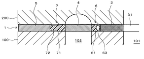
- FIG. 2 is a cross-sectional view taken along line (ii)-(ii) in FIG. 1 showing the cylinder head gasket shown in FIG. 1 interposed between the cylinder block and the cylinder head.
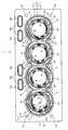
- FIG. 1 is a plan view showing an example of a cylinder head gasket according to the present invention
- FIG. 2 is a cross-sectional view taken along the line (ii)-(ii) in FIG. 1
- FIG. 3 is (iii) in FIG. 4 is a cross-sectional view taken along the line (iii)
- FIG. 4 shows a state in which the cylinder head gasket shown in FIG. 1 is mounted between the cylinder block and the cylinder head along the line (ii)-(ii) in FIG.
- FIG. 4 shows a state in which the cylinder head gasket shown in FIG. 1 is mounted between the cylinder block and the cylinder head along the line (ii)-(ii) in FIG.
- FIG. 1 is a plan view showing an example of a cylinder head gasket according to the present invention
- FIG. 2 is a cross-sectional view taken along the line (ii)-(ii) in FIG. 1
- FIG. 3 is (iii) in FIG.
- the cylinder head gasket 1 is a gasket mounted between the cylinder block 100 and the cylinder head 200 of the engine.
- the cylinder head gasket 1 may have at least the bored plate 3 and the main plate 5. In this case, the bored plate 3 and the main plate 5 are separated without being in contact with each other.
- an intermediate plate 4 corresponding to a water jacket provided around the cylinder bore is provided between the main plate 5 and the bored plate 3.
- the main plate 5, the intermediate plate 4 and the bored plate 3 are separated without contacting each other.
- the bored plate 3 has at least one bore 31 provided corresponding to the cylinder bore of the cylinder block 100.
- the bored plate 3 is formed in a ring shape around a bore 31 corresponding to a cylinder bore 101 formed in the cylinder block 100.
- the bored plates 3 are provided corresponding to the number of cylinder bores 101. In the present embodiment, since the number of the cylinder bores 101 is four, four plates with bored holes 3 are provided corresponding to the number.
- the middle plate 4 corresponds to the water jacket 102 provided around the cylinder bore 101 of the cylinder block 100, and is arranged to close the upper side of the water jacket 102.
- the intermediate plate 4 is formed of a single plate disposed between the bored plate 3 and the main plate 5 and is formed to surround the outer periphery of each bored plate 3 disposed inside. .
- an appropriate number of passage holes 41 for circulating the cooling water in the water jacket 102 are formed.
- the main plate 5 is arranged to surround the bored plate 3 in a mode without the intermediate plate 4.
- the main plate 5 is formed of one plate formed so as to surround the outer periphery of the intermediate plate 4 and constitutes the outermost periphery of the cylinder head gasket 1. That is, all bored plates 3 and the intermediate plate 4 are disposed inside the main plate 5.
- the main plate 5 is formed with an appropriate number of bolt holes 51 for inserting a bolt shaft when the cylinder head 200 is bolted to the cylinder block 100, and an appropriate number of passage holes 52 for circulating oil. ing.
- a seal portion 53 made of a rubber-like elastic material having a bead is provided at the peripheral portion of each flow path hole 52.
- the rubber-like elastic material constituting the seal portion 53 include NBR (nitrile rubber), ACM (acrylic rubber), HNBR (hydrogenated nitrile rubber), FKM (fluororubber) and the like.
- the bored plate 3, the intermediate plate 4 and the main plate 5 are all flat. No seal bead or the like is formed on any of the plates.
- a metal material can be used as a material which forms each plate 3,4,5.
- a metal material aluminum, copper or copper alloy, iron or iron alloy, stainless steel (SUS) etc. are mentioned, for example. From the viewpoint of enhancing the thermal conductivity, aluminum, copper or a copper alloy is preferable, and further, from the viewpoint of manufacturing the gasket, aluminum is preferable.
- Each plate 3, 4, 5 may be formed of the same material, but may be formed of different materials.
- the bored plate 3 near the cylinder bore 101 and the intermediate plate 4 have higher heat than the main plate 5 farthest from the cylinder bore 101
- the cylinder head 200 needs to be conducted.
- the bored plate 3 and the intermediate plate 4 are preferably formed of a material having a thermal conductivity higher than that of the main plate 5.
- the material having high thermal conductivity is preferably made of, for example, aluminum, copper, or a copper alloy.
- adjacent bored plate 3 and intermediate plate 4, intermediate plate 4 and main plate 5 are not in contact with each other but separated and separated by a predetermined distance as described above. .
- the bored plate 3 and the intermediate plate 4, and the intermediate plate 4 and the main plate 5 are connected to each other via the heat insulating members 6 and 7.
- the bored plates 3, the intermediate plate 4 and the main plate 5 are integrated.
- the heat insulating member 6 is provided across the plates 3 and 4 so as to integrally connect the outer peripheral end face 3a of each bored plate 3 and the inner peripheral end face 4a of the intermediate plate 4 respectively.
- the heat insulating member 7 is provided across the plates 4 and 5 so as to integrally connect the outer peripheral end surface 4 b of the intermediate plate 4 and the inner peripheral end surface 5 a of the main plate 5.
- the intermediate plate 4 and the main plate 5 are integrally connected by the heat insulating members 6 and 7, these heat insulating members 6 and 7 can be used to Thermal conduction across the plates 3, 4, 5 is interrupted.
- the heat of each plate 3 with bore holes which becomes the highest temperature, is blocked by the heat insulating member 6 and is hardly transmitted to the intermediate plate 4. Further, the heat of the intermediate plate 4 is also blocked by the heat insulating member 7 and is hardly transmitted to the main plate 5.
- the heat insulating members 6, 7 can connect the adjacent bored plates 3, the intermediate plate 4 and the main plate 5, and thermally insulate between the adjacent bored plates 3, the intermediate plate 4 and the main plate 5 And the material which can prevent the heat conduction of the surface direction of cylinder head gasket 1.
- a specific material is not particularly limited, a rubber-like elastic material is preferable from the viewpoint of being inexpensive and easy to form.
- the heat insulating members 6 and 7 made of a rubber-like elastic material are shown.
- Specific rubber-like elastic materials used for the heat insulating member 6 include FKM (fluorinated rubber), VMQ (silicone rubber) and the like.
- NBR nitrile rubber
- EPDM ethylene propylene rubber
- HNBR hydrogenated nitrile rubber
- FKM fluororubber
- the rubber-like elastic materials (the heat insulating members 6, 7 and the sealing portion 53) used for the cylinder head gasket 1 are all particularly from the viewpoint of combining the integral molding and the manufacturing conditions (secondary vulcanization). It is preferable to use FKM (fluorinated rubber) that can cope with FKM (fluorinated rubber)
- seal beads 61 and 71 on the respective heat insulating members 6 and 7 made of a rubber-like elastic material. As a result, it is not necessary to form the bead by bending the plate, and the cylinder head gasket 1 having the bead can be easily configured.
- the seal beads 61 respectively project on the front and back of the heat insulating member 6 and are formed so as to surround the bored plate 3.
- the seal bead 71 is formed so as to project on the front and back of the heat insulating member 7 and to surround the intermediate plate 4.
- the heat insulating members 6, 7 are made of rubber-like elastic material and the seal beads 61, 71 are integrally formed on the heat insulating members 6, 7, the cylinder head is bolted to the cylinder block with the cylinder head gasket 1 interposed therebetween.
- the bolt fastening load fastening torque
- the seal beads 61 and 71 made of a rubber-like elastic material are compressed to enable sealing.
- the bolt fastening load can be reduced, there is also an effect that the bore deformation can be suppressed. That is, when the bolt fastening load is large, a strong compressive load is applied to the bore portion of the cylinder block, the bore cylinder is distorted, and as a result, the friction of the piston increases, which may cause a decrease in fuel consumption.
- the seal beads 61 and 71 are not metal beads but rubber-like elastic material, compression of the rubber-like elastic material forms a good sealing state even if the bolt fastening load is reduced. be able to. For this reason, generation
- the required rigidity of the engine block can be lowered, weight reduction and cost reduction of the engine block can be expected.
- the heat insulating members 6 and 7 made of a rubber-like elastic material are disposed between the outer peripheral end face 3 a of the bored plate 3 and the inner peripheral end face 4 a of the intermediate plate 4, and the outer peripheral end face 4 b of the intermediate plate 4 and the main plate 5.
- the respective plates 3 with bores, the intermediate plate 4 and the main plate 5 are integrally connected by being separately baked over the peripheral end face 5a.
- the heat insulating members 6 and 7 having the seal beads 61 and 71 have the thickness of the plate 3 with a bored hole, the intermediate plate 4 and the main plate 5 over the entire circumference of the seal beads 61 and 71 on the inner peripheral side or outer peripheral side. It is preferable to have thin portions 62 and 72 formed thin. When the seal beads 61, 71 are compressed between the cylinder block 100 and the cylinder head 200 by the thin portions 62, 72, the deformed seal beads 61, 71 are accommodated in the thin portions 62, 72.
- the bored plate 3, the intermediate plate 4 and the main plate 5 are collectively referred to as the plate if necessary.
- middle plate 4 these are named generically and they are only called a plate as needed.
- the thin portion 62 is formed on the inner peripheral side of each seal bead 61, and the thin portion 72 is formed on the outer peripheral side of the seal bead 71. Since each seal bead 61, 71 is easily deformed so as to fall toward the thin portion 62, 72 when compressed, as shown in FIGS. 2 and 3, the seal bead 61 has an outer peripheral side, a seal bead In 71, the inner peripheral side is the inclined surfaces 61a and 71a, respectively.
- each heat insulating member 6 7 at least a portion disposed between the adjacent bored plates 3, 3, specifically, the heat insulating member 6 connecting the bored plates 3 and the intermediate plate 4; As shown in FIG. 2, it is preferable to form a lightening portion 63 penetrating the front and back of the gasket at a portion disposed between the adjacent bored plates 3, 3.
- two lightening portions 63 including the lightening portion 63 between the adjacent bored plates 3, 3 are formed.
- the portion of the heat insulating member 6 disposed between the bored plates 3, 3 is also exposed to high temperature at all times, so it is a portion with high heat load.
- the through holes 63 form an air layer to exhibit a heat insulating effect. For this reason, the heat load of the heat insulation member 6 can be reduced, and the durability of the heat insulation member 6 can be improved.
- the lightening part 63 is partially provided in the site
- the most preferable cylinder head gasket 1 having the bored plate 3, the intermediate plate 4 and the main plate 5 has been exemplified, but in order to solve the problems of the present invention, It suffices to have a plate. Therefore, it may only have the bored plate and the main plate outside the bored plate, and may further have four or more types of plates. The same applies to the other embodiments described later.
- the bored plate, the intermediate plate, and the main plate are connected via a heat insulating member and a metal bridge member.
- a second embodiment of the present invention will be described.
- the description of the first embodiment is incorporated into the same configuration as that of the first embodiment described above, and the description thereof is omitted.
- FIG. 5 is a plan view showing a second embodiment of a cylinder head gasket according to the present invention
- FIG. 6 is a cross-sectional view along line (vi)-(vi) in FIG. 5, and FIG. (Vii)-(vii) of FIG.
- the difference between the cylinder head gasket 1 and the first embodiment is that the heat insulating member is provided between the bored plate 3 and the intermediate plate 4 or between the bored plate 3 and the intermediate plate 4 and the main plate 5. Not only that, the heat insulating members 6 and 7 are connected to the metal bridge members 8 and 9 respectively.
- metal bridge members 8 and 9 are integrally connected to bored plate 3 and intermediate plate 4, intermediate plate 4 and main plate 5, and have adjacent bored holes.
- the plate 3 and the intermediate plate 4 are connected, and the intermediate plate 4 and the main plate 5 are connected. That is, the bored plate 3 and the main plate 5 are continuous with the bridge members 8 and 9 interposed therebetween.
- the bridge members 8 and 9 can be integrally formed by press forming together with the bored plate 3, the intermediate plate 4 and the main plate 5.
- the bridge members 8 and 9 are formed separately from the bored plate 3, the intermediate plate 4 and the main plate 5 and joined to the bored plate 3, the intermediate plate 4 and the main plate 5. May be
- the bored plate 3, the intermediate plate 4 and the main plate 5 are integrated members before the assembly of the cylinder head gasket, thereby reducing the number of parts. It can be done. Furthermore, handling is easy without the relative positional relationship between the bored plate 3, the intermediate plate 4 and the main plate 5 changing. The absence of changes in the relative positional relationship facilitates assembly and manufacture of the cylinder head gasket.
- At least one bridge member 8, 9 is provided per one bored plate 3.
- the number of the bridge members 8 and 9 should be as small as possible. By reducing the number of heat transfer from the bored plate 3 to the intermediate plate 4 and the main plate 5 by reducing the number of the bridge members 8 and 9, the bored plate 3 and the intermediate plate before assembling the cylinder head gasket 4 and the main plate 5 can be integrated.
- the bridge members 8 and 9 be provided at places where movement such as opening and sliding between the cylinder block 100 and the cylinder head 200 is small, that is, four places near the bolt holes 51 or the like.
- the bridge members 8 and 9 are preferably covered by rubber members 60 and 70.
- the material of the rubber members 60 and 70 may be the same as the rubber-like elastic material mentioned in the heat insulating members 6 and 7 in the first embodiment described above. By covering these rubber members 60 and 70, there is an effect of reinforcing the bridge members 8 and 9.
- the intermediate plate 4 and the bored plate 3 are separated without contact with each other, and they are connected via the heat insulating member, Heat transfer can be suppressed.
- the plates 3, 4 and 5 are separated, there remains a problem that positioning and assembly of the plates 3, 4 and 5 in the rubber baking become complicated.
- Cylinder head gasket 3 Plate with bore 3a: Outer peripheral end face 31: Bore hole 4: Intermediate plate 4a: Inner peripheral end face 4b: Outer peripheral end face 41: Channel hole 5: Main plate 5a: Inner peripheral end face 51: Bolt hole 52: flow passage hole 53: seal portion 6: heat insulation member 61: seal bead 61a: inclined surface 62: thin wall portion 63: thin portion 7: heat insulation member 71: seal bead 71a: inclined surface 72: thin wall portion 8: bridge member 9: Bridge member 60: Rubber member 70: Rubber member
Landscapes
- Engineering & Computer Science (AREA)
- General Engineering & Computer Science (AREA)
- Mechanical Engineering (AREA)
- Chemical & Material Sciences (AREA)
- Combustion & Propulsion (AREA)
- Gasket Seals (AREA)
Abstract
Description
このシリンダヘッドガスケットの面方向の熱伝導は、シリンダヘッド側への熱伝導の効率を低下させ、シリンダブロックとシリンダヘッドとの温度差の早期均一化を妨げる一因となる。
前記シリンダブロックのシリンダボアに対応するボア孔が形成された少なくとも1つのボア孔付きプレートと、前記ボア孔付きプレートを取り囲むように配置されるメインプレートとを備え、
前記ボア孔付きプレート及び前記メインプレートは、互いに接することなく分離され、断熱部材を介して連結されていることを特徴とするシリンダヘッドガスケット。
2.前記メインプレートと前記ボア孔付きプレートとの間に、前記シリンダボアの周囲に設けられたウォータージャケットに対応する中間プレートを有し、
該メインプレートと該中間プレートと該ボア孔付きプレートは、互いに接することなく分離されており、
該メインプレートと該中間プレートと該ボア孔付きプレートは、各々断熱部材を介して連結されていることを特徴とする請求項1記載のシリンダヘッドガスケット。
3.前記断熱部材は、ゴム状弾性材料によって形成されていることを特徴とする請求項1又は2記載のシリンダヘッドガスケット。
4.前記ボア孔付きプレートと前記中間プレートは、前記メインプレートよりも熱伝導性の高い材料によって形成されていることを特徴とする請求項2又は3記載のシリンダヘッドガスケット。
5.前記断熱部材に、シールビードが一体形成されていることを特徴とする請求項1~4の何れかに記載のシリンダヘッドガスケット。
6.前記断熱部材は、前記シールビードの内周側又は外周側に、前記プレートの厚みよりも薄く形成された薄肉部を有していることを特徴とする請求項5記載のシリンダヘッドガスケット。
7.前記断熱部材の部位であって、前記ボア孔付きプレートと、これに隣接するボア孔付きプレートとの間で、シリンダボアからの熱によってより高温になる部位に、ガスケットの表裏に貫通する肉抜き部を形成したことを特徴とする請求項1~6の何れかに記載のシリンダヘッドガスケット。
8.エンジンのシリンダブロックとシリンダヘッドとの間に介装されるシリンダヘッドガスケットであって、
前記シリンダブロックのシリンダボアに対応するボア孔が形成された少なくとも1つのボア孔付きプレートと、前記ボア孔付きプレートを取り囲むように配置されるメインプレートとを備え、
前記ボア孔付きプレート及び前記メインプレートは、断熱部材及び金属製のブリッジ部材を介して連結されていることを特徴とするシリンダヘッドガスケット。
9.前記ブリッジ部材は、1枚のボア孔付きプレートあたりに少なくとも1本が設けられていることを特徴とする請求項8記載のシリンダヘッドガスケット。
10.前記ブリッジ部材は、ゴム部材によって被覆されていることを特徴とする請求項8又は9に記載のシリンダヘッドガスケット。
11.前記断熱部材は、ゴム状弾性材料であることを特徴とする請求項8又は9に記載のシリンダヘッドガスケット。
12.前記断熱部材に、シールビードが一体形成されていることを特徴とする請求項8~11の何れかに記載のシリンダヘッドガスケット。
13.前記断熱部材は、前記シールビードの内周側又は外周側に、前記プレートの厚みよりも薄く形成された薄肉部を有していることを特徴とする請求項12記載のシリンダヘッドガスケット。
14.前記断熱部材の部位であって、前記ボア孔付きプレートと、これに隣接するボア孔付きプレートとの間で、シリンダボアからの熱によってより高温になる部位に、ガスケットの表裏に貫通する肉抜き部を形成したことを特徴とする請求項8~13の何れかに記載のシリンダヘッドガスケット。
この実施形態は、ボア孔付きプレート、中間プレート、メインプレートが互いに接することなく分離され、断熱部材を介して連結されている形態である。
図1は、本発明に係るシリンダヘッドガスケットの一例を示す平面図、図2は、図1中の(ii)-(ii)線に沿う断面図、図3は、図1中の(iii)-(iii)線に沿う断面図、図4は、図1に示すシリンダヘッドガスケットがシリンダブロックとシリンダヘッドとの間に装着された状態を図1中の(ii)-(ii)線に沿って示す断面図である。
特に、シリンダブロック100はシリンダボア101側が最も高温になることを考慮すると、シリンダボア101から最も遠いメインプレート5よりも、シリンダボア101に近いボア孔付きプレート3や中間プレート4の方が、より高い熱をシリンダヘッド200に伝導させる必要がある。このため、本実施形態におけるシリンダヘッドガスケット1では、ボア孔付きプレート3や中間プレート4をメインプレート5よりも熱伝導性の高い材料で形成することが好ましい。熱伝導性の高い材料としては、例えばアルミニウム、銅、銅合金によって形成することが好ましい。
これにより、最も高温になるシリンダボア101の周辺の熱を、シリンダヘッドガスケット1を介して一層効率良くシリンダヘッド200に伝達することができる。
本明細書では、ボア孔付きプレート3、中間プレート4及びメインプレート5を総称して、必要により、単にプレートと称する。なお、中間プレート4がなく、ボア孔付きプレート3及びメインプレート5の態様においても、これらを総称して、必要により、単にプレートと称する。
この実施形態は、ボア孔付きプレート、中間プレート、メインプレートが、断熱部材及び金属製のブリッジ部材を介して連結されている形態である。
以下、本発明の第2の実施形態について説明する。なお、前述の第1の実施形態と同一構成の部分は、第1の実施形態の説明を援用することとし、その説明を省略する。
3:ボア孔付きプレート
3a:外周端面
31:ボア孔
4:中間プレート
4a:内周端面
4b:外周端面
41:流路孔
5:メインプレート
5a:内周端面
51:ボルト孔
52:流路孔
53:シール部
6:断熱部材
61:シールビード
61a:傾斜面
62:薄肉部
63:肉抜き部
7:断熱部材
71:シールビード
71a:傾斜面
72:薄肉部
8:ブリッジ部材
9:ブリッジ部材
60:ゴム部材
70:ゴム部材
Claims (14)
- エンジンのシリンダブロックとシリンダヘッドとの間に介装されるシリンダヘッドガスケットであって、
前記シリンダブロックのシリンダボアに対応するボア孔が形成された少なくとも1つのボア孔付きプレートと、前記ボア孔付きプレートを取り囲むように配置されるメインプレートとを備え、
前記ボア孔付きプレート及び前記メインプレートは、互いに接することなく分離され、断熱部材を介して連結されていることを特徴とするシリンダヘッドガスケット。 - 前記メインプレートと前記ボア孔付きプレートとの間に、前記シリンダボアの周囲に設けられたウォータージャケットに対応する中間プレートを有し、
該メインプレートと該中間プレートと該ボア孔付きプレートは、互いに接することなく分離されており、
該メインプレートと該中間プレートと該ボア孔付きプレートは、各々断熱部材を介して連結されていることを特徴とする請求項1記載のシリンダヘッドガスケット。 - 前記断熱部材は、ゴム状弾性材料によって形成されていることを特徴とする請求項1又は2記載のシリンダヘッドガスケット。
- 前記ボア孔付きプレートと前記中間プレートは、前記メインプレートよりも熱伝導性の高い材料によって形成されていることを特徴とする請求項2又は3記載のシリンダヘッドガスケット。
- 前記断熱部材に、シールビードが一体形成されていることを特徴とする請求項1~4の何れかに記載のシリンダヘッドガスケット。
- 前記断熱部材は、前記シールビードの内周側又は外周側に、前記プレートの厚みよりも薄く形成された薄肉部を有していることを特徴とする請求項5記載のシリンダヘッドガスケット。
- 前記断熱部材の部位であって、前記ボア孔付きプレートと、これに隣接するボア孔付きプレートとの間で、シリンダボアからの熱によってより高温になる部位に、ガスケットの表裏に貫通する肉抜き部を形成したことを特徴とする請求項1~6の何れかに記載のシリンダヘッドガスケット。
- エンジンのシリンダブロックとシリンダヘッドとの間に介装されるシリンダヘッドガスケットであって、
前記シリンダブロックのシリンダボアに対応するボア孔が形成された少なくとも1つのボア孔付きプレートと、前記ボア孔付きプレートを取り囲むように配置されるメインプレートとを備え、
前記ボア孔付きプレート及び前記メインプレートは、断熱部材及び金属製のブリッジ部材を介して連結されていることを特徴とするシリンダヘッドガスケット。 - 前記ブリッジ部材は、1枚のボア孔付きプレートあたりに少なくとも1本が設けられていることを特徴とする請求項8記載のシリンダヘッドガスケット。
- 前記ブリッジ部材は、ゴム部材によって被覆されていることを特徴とする請求項8又は9に記載のシリンダヘッドガスケット。
- 前記断熱部材は、ゴム状弾性材料であることを特徴とする請求項8又は9に記載のシリンダヘッドガスケット。
- 前記断熱部材に、シールビードが一体形成されていることを特徴とする請求項8~11の何れかに記載のシリンダヘッドガスケット。
- 前記断熱部材は、前記シールビードの内周側又は外周側に、前記プレートの厚みよりも薄く形成された薄肉部を有していることを特徴とする請求項12記載のシリンダヘッドガスケット。
- 前記断熱部材の部位であって、前記ボア孔付きプレートと、これに隣接するボア孔付きプレートとの間で、シリンダボアからの熱によってより高温になる部位に、ガスケットの表裏に貫通する肉抜き部を形成したことを特徴とする請求項8~13の何れかに記載のシリンダヘッドガスケット。
Priority Applications (4)
| Application Number | Priority Date | Filing Date | Title |
|---|---|---|---|
| CN201680067479.8A CN108291646B (zh) | 2015-11-20 | 2016-11-18 | 气缸盖密封垫 |
| JP2017527944A JP6202235B1 (ja) | 2015-11-20 | 2016-11-18 | シリンダヘッドガスケット |
| US15/774,532 US10927790B2 (en) | 2015-11-20 | 2016-11-18 | Cylinder head gasket |
| EP16866469.6A EP3379114A4 (en) | 2015-11-20 | 2016-11-18 | ZYLINDERKOPFDICHTUNG |
Applications Claiming Priority (4)
| Application Number | Priority Date | Filing Date | Title |
|---|---|---|---|
| JP2015227730 | 2015-11-20 | ||
| JP2015-227730 | 2015-11-20 | ||
| JP2016081485 | 2016-04-14 | ||
| JP2016-081485 | 2016-04-14 |
Publications (1)
| Publication Number | Publication Date |
|---|---|
| WO2017086469A1 true WO2017086469A1 (ja) | 2017-05-26 |
Family
ID=58718984
Family Applications (1)
| Application Number | Title | Priority Date | Filing Date |
|---|---|---|---|
| PCT/JP2016/084332 Ceased WO2017086469A1 (ja) | 2015-11-20 | 2016-11-18 | シリンダヘッドガスケット |
Country Status (5)
| Country | Link |
|---|---|
| US (1) | US10927790B2 (ja) |
| EP (1) | EP3379114A4 (ja) |
| JP (1) | JP6202235B1 (ja) |
| CN (1) | CN108291646B (ja) |
| WO (1) | WO2017086469A1 (ja) |
Cited By (2)
| Publication number | Priority date | Publication date | Assignee | Title |
|---|---|---|---|---|
| WO2024253043A1 (ja) * | 2023-06-09 | 2024-12-12 | Nok株式会社 | ガスケット |
| WO2026034284A1 (ja) * | 2024-08-08 | 2026-02-12 | Nok株式会社 | ガスケット |
Families Citing this family (3)
| Publication number | Priority date | Publication date | Assignee | Title |
|---|---|---|---|---|
| EP3638930A1 (en) * | 2017-06-15 | 2020-04-22 | Micro Motion, Inc. | Apparatus and method for decreasing flow noise in ring-type joints |
| US11773978B2 (en) * | 2021-03-11 | 2023-10-03 | Dana Automotive Systems Group, Llc | Wire ring combustion seal for automotive engine |
| CN113550838B (zh) * | 2021-08-31 | 2022-03-01 | 湖南省洪江市安达有限责任公司 | 一种复合汽缸盖密封垫 |
Citations (6)
| Publication number | Priority date | Publication date | Assignee | Title |
|---|---|---|---|---|
| JPS5253940U (ja) * | 1975-10-17 | 1977-04-18 | ||
| JPS52120206U (ja) * | 1976-03-10 | 1977-09-12 | ||
| JPS54103451U (ja) * | 1977-12-30 | 1979-07-20 | ||
| US20020074738A1 (en) * | 2000-12-19 | 2002-06-20 | Bjerk Nathan R. | Head gasket and fire ring assembly for optimizing a load distribution |
| JP2002349343A (ja) * | 2001-05-29 | 2002-12-04 | Nok Corp | ヘッドガスケット |
| JP2011144912A (ja) | 2010-01-18 | 2011-07-28 | Sanwa Packing Kogyo Co Ltd | シリンダーヘッドガスケット及びエンジン |
Family Cites Families (8)
| Publication number | Priority date | Publication date | Assignee | Title |
|---|---|---|---|---|
| US4272085A (en) * | 1978-10-07 | 1981-06-09 | Kawasaki Jukogyo Kabushiki Kaisha | Cylinder head gasket for a liquid cooled internal combustion engine |
| FR2645934B1 (fr) * | 1989-04-18 | 1991-07-05 | Curty Soc | Procede de fabrication d'un joint comportant un corps metallique equipe d'au moins un element d'etancheite souple |
| JPH0953726A (ja) * | 1995-08-09 | 1997-02-25 | Marusan:Kk | シリンダヘッドガスケット |
| GB2330182B (en) * | 1997-10-08 | 2001-09-05 | T & N Technology Ltd | Manufacture of gaskets |
| FR2774430B1 (fr) * | 1998-02-05 | 2000-04-21 | Curty Payen Sa | Joint de culasse pour moteur a combustion interne |
| JP2002081543A (ja) | 2000-09-04 | 2002-03-22 | Nippon Gasket Co Ltd | 金属製ガスケット |
| DE102004045142A1 (de) * | 2003-09-17 | 2005-07-07 | Uchiyama Manufacturing Corp. | Zylinderkopfdichtung |
| JP5359770B2 (ja) * | 2009-10-21 | 2013-12-04 | 日本ガスケット株式会社 | シリンダヘッドガスケット |
-
2016
- 2016-11-18 EP EP16866469.6A patent/EP3379114A4/en not_active Withdrawn
- 2016-11-18 CN CN201680067479.8A patent/CN108291646B/zh not_active Expired - Fee Related
- 2016-11-18 US US15/774,532 patent/US10927790B2/en active Active
- 2016-11-18 WO PCT/JP2016/084332 patent/WO2017086469A1/ja not_active Ceased
- 2016-11-18 JP JP2017527944A patent/JP6202235B1/ja active Active
Patent Citations (6)
| Publication number | Priority date | Publication date | Assignee | Title |
|---|---|---|---|---|
| JPS5253940U (ja) * | 1975-10-17 | 1977-04-18 | ||
| JPS52120206U (ja) * | 1976-03-10 | 1977-09-12 | ||
| JPS54103451U (ja) * | 1977-12-30 | 1979-07-20 | ||
| US20020074738A1 (en) * | 2000-12-19 | 2002-06-20 | Bjerk Nathan R. | Head gasket and fire ring assembly for optimizing a load distribution |
| JP2002349343A (ja) * | 2001-05-29 | 2002-12-04 | Nok Corp | ヘッドガスケット |
| JP2011144912A (ja) | 2010-01-18 | 2011-07-28 | Sanwa Packing Kogyo Co Ltd | シリンダーヘッドガスケット及びエンジン |
Non-Patent Citations (1)
| Title |
|---|
| See also references of EP3379114A4 |
Cited By (3)
| Publication number | Priority date | Publication date | Assignee | Title |
|---|---|---|---|---|
| WO2024253043A1 (ja) * | 2023-06-09 | 2024-12-12 | Nok株式会社 | ガスケット |
| JPWO2024253043A1 (ja) * | 2023-06-09 | 2024-12-12 | ||
| WO2026034284A1 (ja) * | 2024-08-08 | 2026-02-12 | Nok株式会社 | ガスケット |
Also Published As
| Publication number | Publication date |
|---|---|
| US10927790B2 (en) | 2021-02-23 |
| CN108291646B (zh) | 2019-10-18 |
| EP3379114A1 (en) | 2018-09-26 |
| EP3379114A4 (en) | 2019-07-24 |
| JPWO2017086469A1 (ja) | 2017-11-16 |
| US20200263630A1 (en) | 2020-08-20 |
| JP6202235B1 (ja) | 2017-09-27 |
| CN108291646A (zh) | 2018-07-17 |
Similar Documents
| Publication | Publication Date | Title |
|---|---|---|
| JP6202235B1 (ja) | シリンダヘッドガスケット | |
| US8246053B2 (en) | Exhaust manifold gasket with spring steel embossed metal and graphite insulator | |
| US6076833A (en) | Metal gasket | |
| JPH11241769A (ja) | 金属製ガスケット | |
| EP1136733A2 (en) | Metallic gasket | |
| JP6246797B2 (ja) | 金属ガスケット | |
| JP2007139177A (ja) | ガスケット | |
| CN105190129B (zh) | 主燃烧密封凸起内的小弹性密封特征 | |
| CN102575615B (zh) | 汽缸盖密封垫 | |
| US20120175847A1 (en) | Support wave stopper in web area of multi-layered steel cylinder head gasket | |
| US20060131817A1 (en) | Gasket assembly for joints experiencing thermally induced movement | |
| JP2003130225A (ja) | メタルガスケット | |
| JP6439161B1 (ja) | 金属製ガスケット | |
| JP5474583B2 (ja) | シリンダーヘッドガスケット及びエンジン | |
| JP6890548B2 (ja) | シリンダブロックとシリンダヘッドとの密封構造 | |
| JP4258980B2 (ja) | エンジンのシール構造 | |
| JP7197759B2 (ja) | ヘッドガスケット | |
| JP2008215467A (ja) | 金属ガスケット | |
| JP3086008B2 (ja) | 金属製ガスケット | |
| JP3404098B2 (ja) | シリンダヘッドガスケット | |
| JP2007057063A (ja) | ガスケット | |
| CN115822807A (zh) | 缸垫和发动机 | |
| JP6308192B2 (ja) | レシプロ式エンジン | |
| JP2008014223A (ja) | 内燃機関用ピストン | |
| JP2006037737A (ja) | ピストン式内燃機関 |
Legal Events
| Date | Code | Title | Description |
|---|---|---|---|
| ENP | Entry into the national phase |
Ref document number: 2017527944 Country of ref document: JP Kind code of ref document: A |
|
| 121 | Ep: the epo has been informed by wipo that ep was designated in this application |
Ref document number: 16866469 Country of ref document: EP Kind code of ref document: A1 |
|
| WWE | Wipo information: entry into national phase |
Ref document number: 12018501064 Country of ref document: PH |
|
| NENP | Non-entry into the national phase |
Ref country code: DE |
|
| WWE | Wipo information: entry into national phase |
Ref document number: 2016866469 Country of ref document: EP |