WO2017092004A1 - Systèmes et procédés pour la protection de composant - Google Patents
Systèmes et procédés pour la protection de composant Download PDFInfo
- Publication number
- WO2017092004A1 WO2017092004A1 PCT/CN2015/096316 CN2015096316W WO2017092004A1 WO 2017092004 A1 WO2017092004 A1 WO 2017092004A1 CN 2015096316 W CN2015096316 W CN 2015096316W WO 2017092004 A1 WO2017092004 A1 WO 2017092004A1
- Authority
- WO
- WIPO (PCT)
- Prior art keywords
- chamber
- liquid
- component
- inner container
- outer container
- Prior art date
- Legal status (The legal status is an assumption and is not a legal conclusion. Google has not performed a legal analysis and makes no representation as to the accuracy of the status listed.)
- Ceased
Links
Images




Classifications
-
- F—MECHANICAL ENGINEERING; LIGHTING; HEATING; WEAPONS; BLASTING
- F25—REFRIGERATION OR COOLING; COMBINED HEATING AND REFRIGERATION SYSTEMS; HEAT PUMP SYSTEMS; MANUFACTURE OR STORAGE OF ICE; LIQUEFACTION SOLIDIFICATION OF GASES
- F25B—REFRIGERATION MACHINES, PLANTS OR SYSTEMS; COMBINED HEATING AND REFRIGERATION SYSTEMS; HEAT PUMP SYSTEMS
- F25B21/00—Machines, plants or systems, using electric or magnetic effects
- F25B21/02—Machines, plants or systems, using electric or magnetic effects using Peltier effect; using Nernst-Ettinghausen effect
- F25B21/04—Machines, plants or systems, using electric or magnetic effects using Peltier effect; using Nernst-Ettinghausen effect reversible
-
- F—MECHANICAL ENGINEERING; LIGHTING; HEATING; WEAPONS; BLASTING
- F16—ENGINEERING ELEMENTS AND UNITS; GENERAL MEASURES FOR PRODUCING AND MAINTAINING EFFECTIVE FUNCTIONING OF MACHINES OR INSTALLATIONS; THERMAL INSULATION IN GENERAL
- F16F—SPRINGS; SHOCK-ABSORBERS; MEANS FOR DAMPING VIBRATION
- F16F15/00—Suppression of vibrations in systems; Means or arrangements for avoiding or reducing out-of-balance forces, e.g. due to motion
- F16F15/02—Suppression of vibrations of non-rotating, e.g. reciprocating systems; Suppression of vibrations of rotating systems by use of members not moving with the rotating systems
- F16F15/022—Suppression of vibrations of non-rotating, e.g. reciprocating systems; Suppression of vibrations of rotating systems by use of members not moving with the rotating systems using dampers and springs in combination
-
- G—PHYSICS
- G01—MEASURING; TESTING
- G01C—MEASURING DISTANCES, LEVELS OR BEARINGS; SURVEYING; NAVIGATION; GYROSCOPIC INSTRUMENTS; PHOTOGRAMMETRY OR VIDEOGRAMMETRY
- G01C21/00—Navigation; Navigational instruments not provided for in groups G01C1/00 - G01C19/00
- G01C21/10—Navigation; Navigational instruments not provided for in groups G01C1/00 - G01C19/00 by using measurements of speed or acceleration
- G01C21/12—Navigation; Navigational instruments not provided for in groups G01C1/00 - G01C19/00 by using measurements of speed or acceleration executed aboard the object being navigated; Dead reckoning
- G01C21/16—Navigation; Navigational instruments not provided for in groups G01C1/00 - G01C19/00 by using measurements of speed or acceleration executed aboard the object being navigated; Dead reckoning by integrating acceleration or speed, i.e. inertial navigation
- G01C21/166—Mechanical, construction or arrangement details of inertial navigation systems
-
- G—PHYSICS
- G06—COMPUTING OR CALCULATING; COUNTING
- G06F—ELECTRIC DIGITAL DATA PROCESSING
- G06F1/00—Details not covered by groups G06F3/00 - G06F13/00 and G06F21/00
- G06F1/16—Constructional details or arrangements
- G06F1/18—Packaging or power distribution
- G06F1/181—Enclosures
- G06F1/182—Enclosures with special features, e.g. for use in industrial environments; grounding or shielding against radio frequency interference [RFI] or electromagnetical interference [EMI]
-
- G—PHYSICS
- G06—COMPUTING OR CALCULATING; COUNTING
- G06F—ELECTRIC DIGITAL DATA PROCESSING
- G06F1/00—Details not covered by groups G06F3/00 - G06F13/00 and G06F21/00
- G06F1/16—Constructional details or arrangements
- G06F1/20—Cooling means
- G06F1/206—Cooling means comprising thermal management
-
- F—MECHANICAL ENGINEERING; LIGHTING; HEATING; WEAPONS; BLASTING
- F25—REFRIGERATION OR COOLING; COMBINED HEATING AND REFRIGERATION SYSTEMS; HEAT PUMP SYSTEMS; MANUFACTURE OR STORAGE OF ICE; LIQUEFACTION SOLIDIFICATION OF GASES
- F25B—REFRIGERATION MACHINES, PLANTS OR SYSTEMS; COMBINED HEATING AND REFRIGERATION SYSTEMS; HEAT PUMP SYSTEMS
- F25B2321/00—Details of machines, plants or systems, using electric or magnetic effects
- F25B2321/02—Details of machines, plants or systems, using electric or magnetic effects using Peltier effects; using Nernst-Ettinghausen effects
- F25B2321/023—Mounting details thereof
-
- G—PHYSICS
- G06—COMPUTING OR CALCULATING; COUNTING
- G06F—ELECTRIC DIGITAL DATA PROCESSING
- G06F2200/00—Indexing scheme relating to G06F1/04 - G06F1/32
- G06F2200/20—Indexing scheme relating to G06F1/20
- G06F2200/201—Cooling arrangements using cooling fluid
Definitions
- Controllers on-board movable devices may be exposed to vibration or impact as the movable object may move around or collide with other objects.
- the controllers may also be exposed to temperature or pressure variations which may affect operation of the controllers.
- the protective devices may protect the components from vibration or impact, and/or fluctuations in temperature and/or pressure. This may be useful when movable objects are moving within an environment and undergoing vibrations, or are at risk for impact or collision. For instance, the movable objects may be at risk for being hit by a projectile.
- the movable objects may be vehicles, such as unmanned vehicles.
- the movable objects may be robots that may perform a task.
- the components may be electronic components that may affect operation of the movable object.
- the component may be a controller that may affect propulsion and/or movement of the movable object.
- Additional aspects of the invention are directed to a method for protecting a component, said method comprising: enclosing a component that is to be protected within a chamber, wherein the chamber is configured to contain a liquid that surrounds the component, wherein the liquid is configured to reduce an amount of an impact on the chamber that is transferred to the component; and providing a temperature control system configured to permit heating and cooling of the liquid.
- a component protection apparatus may be provided.
- the apparatus may comprise: an inner container comprising a rounded shape, wherein the inner container is configured to support a component that is to be protected within the inner container; a chamber comprising a rounded shape that encloses the inner container, wherein the inner container is supported within the chamber; an outer container comprising a rounded shape that encloses the chamber, wherein the chamber is supported within the outer container; and a liquid within at least one of the inner container, the chamber, or the outer container, said liquid configured to reduce an amount of an impact on the outer container that is transferred to the component.
- a movable object may comprise: one or more propulsion units; and a component protection assembly as previously described, wherein the component communicates with the one or more propulsion units.
- aspects of the invention may be directed to a component protection apparatus, said apparatus comprising: an inner container, wherein the inner container is configured to support a component that is to be protected within the inner container; a chamber that encloses the inner container, wherein the inner container is supported within the chamber in a manner that reduces an amount of impact on the chamber that is transferred to the inner container by a first amount; and an outer container that encloses the chamber, wherein the chamber is supported within the outer container in a manner that reduces an amount of impact on the chamber that is transferred to the inner container by a second amount that is greater than the first amount.
- a movable object may comprise: one or more propulsion units; and a component protection assembly as previously described, wherein the component communicates with the one or more propulsion units.
- Additional aspects of the invention may provide a method of protecting a component, said method comprising: supporting a component that is to be protected within an inner container; enclosing the inner container within, wherein the inner container is supported within the chamber in a manner that reduces an amount of impact on the chamber that is transferred to the inner container by a first amount; and enclosing the chamber within an outer container, wherein the chamber is supported within the outer container in a manner that reduces an amount of impact on the chamber that is transferred to the inner container by a second amount that is greater than the first amount.
- FIG. 1 shows an example of a component protection apparatus in accordance with embodiments of the invention.
- FIG. 2 shows an example of a component protection apparatus that includes a temperature control system in accordance with embodiments of the invention.
- FIG. 3 shows an example of a component protection apparatus with a temperature control system and a pressure adjustment system in accordance with embodiments of the invention.
- FIG. 4 shows an example of a component protection apparatus that reduces effects of external forces on the component in accordance with embodiments of the invention.
- FIG. 5 shows an additional view of a component protection apparatus that reduces effects of external forces on the component in accordance with embodiments of the invention.
- FIG. 6 provides a further view of a component protection apparatus that reduces effects of external forces on the component in accordance with embodiments of the invention.
- FIG. 7 provides an external view of a component protection apparatus that reduces effects of external forces on the component in accordance with embodiments of the invention.
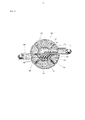
- FIG. 8 shows a view of a chamber of a component protection apparatus in accordance with embodiments of the invention.
- FIG. 9 shows a view of an inner container of a component protection apparatus in accordance with embodiments of the invention.
- FIG. 10 shows an example of a dampening mechanism for a component protection apparatus in accordance with embodiments of the invention.
- FIG. 11 shows an example of electrical connections for a component in a component protection apparatus in accordance with embodiments of the invention.
- FIG. 12 shows an example of a movable object with a component protection apparatus in accordance with embodiments of the invention.
- FIG. 13 shows an example of a movable object including a carrier and a payload, in accordance with embodiments of the invention.
- the movable object may subject the component to vibrations and/or impact that may affect operation of the component.
- the component may be an electronic component that may affect operation of the movable object.
- the component may be a flight controller of an unmanned aerial vehicle (UAV).
- UAV unmanned aerial vehicle
- the component may affect propulsion, communications, data collection or sensing, power distribution, or any other function of the movable object.
- a component protection apparatus may protect the component from the vibrations and/or impacts. For instance, force of impact on the movable object and/or component protection apparatus may be reduced for the component.
- one or more layers of containers may be provided to protect the component from the vibrations or impacts. Dampeners may be provided between the layers of containers to reduce the force of impact.
- liquid may be provided within one or more layers of containers. The liquid may also reduce the force of impact delivered to a component.
- the component protection apparatus may also include a temperature control mechanism.
- the movable object may be subjected to varying temperatures. For instance, if a movable object is traversing an environment, such as different altitudes or levels of shade, the movable object may be exposed to widely changing temperatures that may affect operation of the component.
- the temperature control mechanism may control the temperature to which the component is exposed.
- the component protection apparatus may include a liquid, and the temperature of the liquid may be controlled.
- the component protection apparatus may also include a pressure adjustment mechanism.
- a pressure of a liquid within the component protection apparatus may be controlled.
- the pressure may be controlled to affect the level of vibration and/or impact reduction that experienced by the component.
- the pressure may be controlled based on an environmental pressure around the movable object, or independent of an environmental pressure around the movable object.
- the pressure adjustment mechanism may be operated in conjunction with a temperature control mechanism.
- a pressure of a liquid may be adjusted in response to a temperature adjustment.
- the components in the component protection apparatus may be electrically connected to one or more other components of the movable object.
- the component protection apparatus may provide electrical connections. This may permit the protected components to affect the movable object while remaining physically protected.
- FIG. 1 shows an example of a component protection apparatus in accordance with embodiments of the invention.
- a component protection apparatus 100 may include a chamber 102 that encloses a component 104.
- a liquid 106 may be provided within the chamber that may reduce a force of impact experienced by the component.
- Zero, one, or more outer supports 108 may be provided outside the chamber.
- Zero, one, or more inner supports 110 may be provided within the chamber.
- one or more dampeners 112 may be provided between an outer support and the chamber.
- one or more dampeners 114 may be provided between the chamber and an inner support.
- one or more dampeners 116 may be provided between an inner support and a component.
- a chamber 102 may be provided to enclose a component 104. Any description herein of chamber, may also be referred to as an intermediary chamber, a container (or intermediary container), shell (or intermediary shell), cage (or intermediary cage), structure (or intermediary structure), or vice versa.
- the chamber may be completely enclosing the component or at least partially enclosing the component. Any description herein of a chamber enclosing a component may include a partial enclosure of the component.
- the chamber may enclose the component by surrounding the component at least 360 degrees, 270 degrees, 180 degrees, or 90 degrees laterally. In some instances, the chamber may enclose the component by surrounding the component at least 360 degrees, 270 degrees, 180 degrees, or 90 degrees vertically. In some instances, the component may be surrounded on all angles by the chamber.
- the chamber may be a fluid-tight.
- the chamber may isolate fluids inside the chamber from fluids outside the chamber.
- the chamber may be gas (air) tight or liquid-tight.
- the chamber may prevent liquid or gas from within the chamber to leave the chamber.
- the chamber may prevent liquid or gas from outside the chamber from entering the chamber.
- the chamber may prevent a component from falling outside the chamber or escaping the chamber.
- the chamber may include solid walls.
- the walls of the chamber may be opaque, translucent, or transparent.
- the walls may have little or no porosity.
- the walls may have pores, channels, conduits, holes, openings, windows, cut-outs or any other configuration that may allow fluid communication through the walls.
- the walls may be formed as netting, mesh, textile, or have any other configuration.
- the chamber may be formed from a rigid material.
- the chamber may be formed from a flexible or resilient material. In some instances, the chamber may be formed from an elastomeric material.
- the chamber may be formed from plastic, silicone, metal, glass, rubber, metal or any other materials or combinations thereof.
- the chamber may be capable of deforming on impact. The chamber may or may not spring back to its original shape after impact.
- the chamber may be able to withstand an impact force of at least 100 N, 500 N, 1 kN, 2 kN, 3 kN, 5 kN, 7 kN, 10 kN, 15 kN, 20 kN, 25 kN, 30 kN, 40 kN, 50 kN, 75 kN, 100 kN, 200 kN, 300 kN, or 500 kN without deforming, or without being damaged.
- the chamber may be able to withstand an impact of force of any value described herein without damaging any item enclosed within the chamber, or without damaging the component enclosed within the chamber.
- the chamber may be formed from a material that is an electrical insulator.
- the material may have a high resistivity.
- the material may have an electrical resistivity of greater than or equal to about 10, 10 2 , 10 3 , 10 4 , 10 5 , 10 6 , 10 7 , 10 8 , 10 9 , 10 10 , 10 11 , 10 12 , 10 13 , 10 14 , or 10 15 ohm m.
- the chamber may be formed from a material that is a thermal insulator.
- the material may have a thermal insulation value (e.g., R-value) of greater than or equal to at least about 0.10, 0.15, 0.20, 0.25, 0.30, 0.35, 0.40, 0.45, 0.50, 0.55, 0.60, 0.65, 0.70, 0.75, 0.80, 0.90, 1.0, 1.1, or 1.2 m 2 ⁇ K / w ⁇ in.
- the material may have an R-value less than any of the values described.
- the material may have an R-value falling within a range between any two of the values described.
- the chamber may have any shape.
- the chamber may be substantially spherical.
- the chamber may have a substantially rounded shape, such as a sphere, ovoid, or ellipsoid.
- the chamber may have rounded features without any sharp points or edges.
- the chamber may be shaped with one or more points or edges.
- the chamber may be a cube, cuboid, cylinder, polygonal prism (e.g., triangular prism, quadrilateral prism, pentagonal prism, hexagonal prism, octagonal prism), cone, tetrahedron, square pyramid, hemisphere, octahedron, dodecahedron, or any other shapes or combinations thereof.
- the chamber may have any size.
- the chamber may enclose a volume of less than or equal to about 100,000 cm 3 , 50,000 cm 3 , 10,000 cm 3 , 5,000 cm 3 , 1,000 cm 3 , 750 cm 3 , 500 cm 3 , 300 cm 3 , 250 cm 3 , 200 cm 3 , 150 cm 3 , 100 cm 3 , 75 cm 3 , 50 cm 3 , 30 cm 3 , 25 cm 3 , 20 cm 3 , 15 cm 3 , 10 cm 3 , 7 cm 3 , 5 cm 3 , 3 cm 3 , 2 cm 3 , 1 cm 3 , 0.5 cm 3 , or 0.1 cm 3 .
- the chamber may enclose a volume greater than or equal to any of the values described.
- the chamber may enclose a volume within a range falling between any two of the values described.
- the chamber may have a maximum dimension (length, width, height, diagonal, diameter) of less than or equal to about 100 cm, 75 cm, 50 cm, 40 cm, 30 cm, 20 cm, 15 cm, 10 cm, 9 cm, 8 cm, 7 cm, 6 cm, 5 cm, 4 cm, 3 cm, 2 cm, 1 cm, 5 mm, 3 mm, 1 mm, 0.5 mm, or 0.1 mm.
- the chamber may have a maximum dimension that is greater than any of the values described.
- the chamber may have a maximum value within a range falling between any two of the values described.
- a component 104 may be enclosed within the chamber 102.
- the component may be a component to be protected with aid of the chamber.
- the component may be a component that may experience a reduced force of impact with aid of the chamber.
- the component may be an electronic component.
- the component may include one or more processors and/or one or more memory storage units.
- the component may be configured to execute code, programs, or instructions provided by non-transitory media.
- the component may include one or more circuits or chips (e.g., application-specific integrated circuits (ASICs)).
- the component may operate on electrical power.
- the component may be capable of operating while being protected by a component protection apparatus.
- the component may be capable of receiving power and/or data, and/or transmitting data while being protected by a component protection apparatus.
- the component may be a controller of one or more other components of a movable object.
- the component may be a flight controller.
- the component may generate a signal that may affect operation of one or more propulsion units of a movable object.
- the component may generate a signal that may affect operation of a communications unit, one or more sensors, a power storage or distribution system, a carrier, a payload, a navigation system, a landing system, an emitter (e.g., lighting or sound system), or any other component of the movable object.
- the component may store data.
- the component may store data collected or generated during operation of the movable object.
- the component may store data about a state of a movable object (e.g., positioning, orientation, movement, location, power usage, detected errors or malfunctions, communications operations, actions performed by the movable object) and/or any data about a state of an environment of the movable object, which may be collected by one or more sensors of the movable object (e.g., images of the environment).
- the component may store data about communications received by the movable object (which may include navigational or operational commands from an external device) and/or sent by the movable object.
- the component may function as a black box for the movable object and it may be desirable to make the component resistant to damage.
- the component may be a sensor.
- the component may be an inertial sensor.
- the component may be part of an inertial measurement unit (IMU).
- the component may include one or more gyroscopes, accelerometers, magnetometers, or any other type of inertial sensor.
- the component may be able to detect a position of to one or more, two or more, or three or more spatial directions (e.g., along one, two, or three or more axes).
- the component may be able to detect an orientation about one or more, two or more, or three or more axes.
- the component may similarly be able to detect movement, such as linear velocity, linear acceleration, angular velocity, or angular acceleration with respect to one, two, or three or more axes.
- the component may be able to detect a direction of gravity and relative positioning with respect to the direction of gravity.
- the component may be able to detect forces or moments experienced by the component.
- sensors may include one or more of the following: one or more sensors can comprise one or more of: a global positioning system (GPS) sensor, a vision sensor, a temperature sensor, a lidar sensor, an ultrasonic sensor, a barometer, or an altimeter.
- GPS global positioning system
- sensors can comprise one or more of: a global positioning system (GPS) sensor, a vision sensor, a temperature sensor, a lidar sensor, an ultrasonic sensor, a barometer, or an altimeter.
- GPS global positioning system
- Any sensor suitable for collecting environmental information can be used, including location sensors (e.g., GPS sensors, mobile device transmitters enabling location triangulation), vision sensors (e.g., imaging devices capable of detecting visible, infrared, or ultraviolet light, such as cameras), proximity sensors (e.g., ultrasonic sensors, lidar, time-of-flight cameras), inertial sensors (e.g., accelerometers, gyroscopes, inertial measurement units (IMUs)), altitude sensors, pressure sensors (e.g., barometers), audio sensors (e.g., microphones) or field sensors (e.g., magnetometers, electromagnetic sensors). Any suitable number and combination of sensors can be used, such as one, two, three, four, five, or more sensors.
- location sensors e.g., GPS sensors, mobile device transmitters enabling location triangulation
- vision sensors e.g., imaging devices capable of detecting visible, infrared, or ultraviolet light, such as cameras
- proximity sensors e.g., ultra
- any description herein of a component may apply to one or more separate pieces.
- any description herein of a component may encompass a single or multiple processors, chips, memory units, sensors, and/or any combinations thereof.
- the pieces of the component may share a common substrate or be connected to one another.
- the separate pieces of the component may be separable.
- the pieces of the component may remain at fixed positions relative to one another.
- the pieces of the component may be movable relative to one another.
- the component 104 may have a fixed position relative to the chamber 102.
- the component may be rigidly disposed so that it does not move relative to the chamber during operation of the movable object.
- the component may remain at a fixed position relative to chamber even upon impact.
- the component may move relative to the chamber upon impact.
- the component may have a movable position relative to the chamber.
- the component may be flexibly disposed so that it may be permitted to move relative to the chamber during operation of the movable object. Vibrations experienced by the chamber may be reduced or removed for the component.
- one or more dampeners 114, 116 may be provided between the component and the chamber.
- the chamber may optionally enclose a liquid 106.
- the liquid may be substantially contained within the chamber.
- the liquid may, in some embodiments, only escape or enter the chamber through controlled conduits.
- the liquid may remain substantially static within the chamber, or may flow.
- the liquid may surround the component. In some instances, the liquid may surround the component about 360 degrees laterally and/or about 360 degrees vertically.
- the liquid may completely surround the component.
- the liquid may or may not directly contact the component.
- the liquid may or may not directly contact an inner surface of a chamber wall.
- the liquid may be a dielectric liquid.
- the liquid may be an electric insulator.
- the liquid may have a high resistivity.
- the liquid may have an electrical resistivity of greater than or equal to about 10, 10 2 , 10 3 , 10 4 , 10 5 , 10 6 , 10 7 , 10 8 , 10 9 , 10 10 , 10 11 , 10 12 , 10 13 , 10 14 , or 10 15 ohm m.
- the liquid may have an electrical resistivity lower than any of the values described or falling within a range between any two of the values described.
- the liquid may have any desired viscosity.
- the liquid may have the same viscosity as water, a lower viscosity than water, or a greater viscosity than water.
- the liquid may have a viscosity of greater than or equal to 10 -4 , 10 -3 , 10 -2 , 0.1, 0.5, 1, 1.2, 1.3, 1.4, or 1.5 Pa s at 25 degrees C.
- the liquid may have a viscosity lower than any of the values described or falling within a range between any two of the values described.
- the liquid may be a stable liquid with a long lifetime.
- the properties of the liquid may not change substantially over at least 1 month, 3 months, 6 months, 1 year, 1.5 years, 2 years, 3 years, 4 years, 5 years, 7 years, 10 years, 15 years, or 20 years.
- the liquid may be an oil.
- the liquid may be a hydraulic oil such as phosphate ester hydraulic oil, or water – ethylene glycol hydraulic oil.
- the liquid may be an oil-in-water emulsion or a water-in-oil emulsion.
- the liquid may be a solvent.
- the liquid may be ethyl alcohol or liquid silicone.
- the liquid may be an ethyl acetate, ethyl benzoate, ethyl lactate, or cyclohexanone.
- the chamber may include a fluid.
- the fluid may be a liquid as described herein.
- the fluid may be a gas.
- the fluid may be air.
- the fluid may have the same weight or weigh less than air.
- the fluid may be an inert gas.
- the fluid may be electrically insulative (e.g., have any of the resistivity values described elsewhere herein).
- one or more outer supports 108 may be provided outside the chamber 102.
- no outer supports may be provided outside the chamber.
- Any description herein of an outer support may apply to multiple outer supports.
- a single layer of outer support may be provided outside the chamber.
- multiple layers of outer supports may be provided outside the chamber (e.g., one or more, two or more, three or more, four or more, five or more, six or more layers of outer support).
- two layers of outer support may include a first outer layer, which may enclose a second outer layer, which may enclose the chamber.
- Any description herein of an outer support may apply to a single layer of outer support or multiple layers of outer support.
- the outer support may be provided to enclose a chamber. Any description herein of an outer support may also be referred to as an outer container, outer chamber, outer shell, outer cage, outer structure, or vice versa.
- the outer support may be completely enclosing the chamber or at least partially enclosing the chamber. Any description herein of an outer support enclosing a chamber may include a partial enclosure of the chamber.
- the outer support may enclose the chamber by surrounding the chamber at least 360 degrees, 270 degrees, 180 degrees, or 90 degrees laterally. In some instances, the outer support may enclose the chamber by surrounding the chamber at least 360 degrees, 270 degrees, 180 degrees, or 90 degrees vertically. In some instances, the chamber may be surrounded on all angles by the outer support.
- the outer support may be a fluid-tight. In some instances, the outer support may isolate fluids inside the outer support from fluids outside the outer support.
- the outer support may be gas (air) tight or liquid-tight. For instance, the outer support may prevent liquid or gas from within the outer support to leave the outer support.
- the outer support may prevent liquid or gas from outside the outer support from entering the outer support.
- the outer support may prevent a chamber from falling outside the outer support or escaping the outer support.
- the outer support may include solid walls.
- the walls of the outer support may be opaque, translucent, or transparent. The walls may have little or no porosity. Alternatively, the walls may have pores, channels, conduits, holes, openings, windows, cut-outs or any other configuration that may allow fluid communication through the walls.
- the walls may be formed as netting, mesh, textile, or have any other configuration.
- the outer support may optionally have a bracket configuration.
- the walls may be made from a gas permeable or gas impermeable material.
- the walls may be made from a liquid permeable or liquid impermeable material.
- the outer support may include one or more structural support without requiring full walls. For instance, a skeleton structure may be provided to define a shape of the outer support without requiring walls.
- the outer support may directly or indirect bear weight of the chamber.
- the outer support may be formed from a rigid material.
- the outer support may be formed from a flexible or resilient material. In some instances, the outer support may be formed from an elastomeric material.
- the outer support may be formed from plastic, silicone, metal, glass, rubber, metal or any other materials or combinations thereof.
- the outer support may be capable of deforming on impact. The outer support may or may not spring back to its original shape after impact.
- the outer support may be able to withstand an impact force of at least 100 N, 500 N, 1 kN, 2 kN, 3 kN, 5 kN, 7 kN, 10 kN, 15 kN, 20 kN, 25 kN, 30 kN, 40 kN, 50 kN, 75 kN, 100 kN, 200 kN, 300 kN, or 500 kN without deforming, or without being damaged.
- the outer support may be able to withstand an impact of force of any value described herein without damaging any item enclosed within the outer support, or without damaging the chamber enclosed within the outer support.
- the outer support may be formed from a material that is an electrical insulator.
- the material may have a high resistivity.
- the material may have an electrical resistivity of greater than or equal to about 10, 10 2 , 10 3 , 10 4 , 10 5 , 10 6 , 10 7 , 10 8 , 10 9 , 10 10 , 10 11 , 10 12 , 10 13 , 10 14 , or 10 15 ohm m.
- the outer support may be formed from an electrically conductive material.
- the outer support may be formed from a material that is a thermal insulator.
- the material may have a thermal insulation value (e.g., R-value) of greater than or equal to at least about 0.10, 0.15, 0.20, 0.25, 0.30, 0.35, 0.40, 0.45, 0.50, 0.55, 0.60, 0.65, 0.70, 0.75, 0.80, 0.90, 1.0, 1.1, or 1.2 m 2 ⁇ K / w ⁇ in.
- the material may have an R-value less than any of the values described.
- the material may have an R-value falling within a range between any two of the values described.
- the outer support may be formed from the same material as the chamber or may share one or more material properties with the chamber. Alternatively, the outer support may be formed from a different material as the chamber or may have one or more material properties different from the chamber.
- the outer support may have any shape.
- the outer support may be substantially spherical.
- the outer support may have a substantially rounded shape, such as a sphere, ovoid, or ellipsoid.
- the outer support may have rounded features without any sharp points or edges.
- the chamber may be shaped with one or more points or edges.
- the outer support may be a cube, cuboid, cylinder, polygonal prism (e.g., triangular prism, quadrilateral prism, pentagonal prism, hexagonal prism, octagonal prism), cone, tetrahedron, square pyramid, hemisphere, octahedron, dodecahedron, or any other shapes or combinations thereof.
- polygonal prism e.g., triangular prism, quadrilateral prism, pentagonal prism, hexagonal prism, octagonal prism
- cone tetrahedron
- square pyramid hemisphere
- octahedron dodecahedron
- dodecahedron or any other shapes or combinations thereof.
- the outer support may have the same shape as the chamber. Alternatively, the outer support may have a different shape from the chamber.
- the outer support and the chamber may be concentrically located. A center of the outer support and a center of the chamber may be at the same location in space, or may be very close to one another (e.g., within 1 mm, 3 mm, 5 mm, 7 mm, 1 cm, 2 cm, 3 cm, 5 cm, 7 cm, or 10 cm of one another).
- the center of gravity of the outer support and the center of gravity of the chamber may be at the same location in space, or may be very close to one another (e.g., within 1 mm, 3 mm, 5 mm, 7 mm, 1 cm, 2 cm, 3 cm, 5 cm, 7 cm, or 10 cm of one another).
- the outer support may have any size.
- the outer support may enclose a volume of less than or equal to about 200,000 cm 3 , 100,000 cm 3 , 50,000 cm 3 , 10,000 cm 3 , 5,000 cm 3 , 1,000 cm 3 , 750 cm 3 , 500 cm 3 , 300 cm 3 , 250 cm 3 , 200 cm 3 , 150 cm 3 , 100 cm 3 , 75 cm 3 , 50 cm 3 , 30 cm 3 , 25 cm 3 , 20 cm 3 , 15 cm 3 , 10 cm 3 , 7 cm 3 , 5 cm 3 , 3 cm 3 , 2 cm 3 , 1 cm 3 , 0.5 cm 3 , or 0.1 cm 3 .
- the outer support may enclose a volume greater than or equal to any of the values described.
- the outer support may enclose a volume within a range falling between any two of the values described.
- the outer support may have a maximum dimension (length, width, height, diagonal, diameter) of less than or equal to about 200 cm, 150 cm, 100 cm, 75 cm, 50 cm, 40 cm, 30 cm, 20 cm, 15 cm, 10 cm, 9 cm, 8 cm, 7 cm, 6 cm, 5 cm, 4 cm, 3 cm, 2 cm, 1 cm, 5 mm, 3 mm, 1 mm, 0.5 mm, or 0.1 mm.
- the outer support may have a maximum dimension that is greater than any of the values described.
- the outer support may have a maximum value within a range falling between any two of the values described.
- the outer support may be larger than the chamber.
- the outer support may be sufficiently large such that an inner surface of the outer support may be larger than an outer surface of the chamber.
- the outer support and the chamber may be arranged so that an inner surface of the outer support does not contact an outer surface of the chamber when the movable object is at rest or in normal operation.
- An inner surface of the outer support may or may not contact the outer surface of the chamber in the event of a collision of the movable object or a hit by an object on the movable object.
- the outer support may optionally enclose a fluid.
- the fluid may be a gas.
- the fluid may be a liquid, which may have any property or characteristics of a liquid as described elsewhere herein.
- the fluid may be substantially contained within the outer support.
- the fluid may, in some embodiments, only escape or enter the outer support through controlled conduits.
- the fluid may remain substantially static within the outer support, or may flow.
- the fluid may surround the chamber. In some instances, the fluid may surround the chamber about 360 degrees laterally and/or about 360 degrees vertically.
- the fluid may completely surround the chamber.
- the fluid may or may not directly contact the outer surface of the chamber.
- the fluid may or may not directly contact an inner surface of an outer support.
- the fluid may be a gas.
- the fluid may be air.
- the flight may be a gas that is lighter than air.
- the fluid may be an inert gas.
- the fluid may be kept at a pressure that is equal to ambient pressure around the movable object.
- the fluid may be at a pressure that is greater than ambient pressure, or that is lower than ambient pressure.
- the fluid between the outer support and chamber may be the same as a fluid within a chamber or may be different from a fluid within a chamber.
- the fluid outside the chamber may be a gas while fluid within a chamber may be a liquid.
- both fluid within and outside the chamber may be a gas, or may be a liquid.
- one or more dampeners 112 may be provided between the chamber 102 and the outer support 108.
- the dampeners may permit movement between the chamber and the outer support. In some instances, the dampeners may not cause movement between the chamber and the outer support when the chamber and outer support are at rest.
- the dampeners may reduce the amount of force experienced by the chamber, relative to the outer support.
- the dampeners may reduce the amount of vibration experienced by the chamber, relative to the outer support.
- the dampeners may suspend the chamber within the outer support.
- the dampeners may prevent the outer surface of the chamber from coming into contact with an inner surface of the outer support. A fluid within an outer support may or may not directly contact a dampener.
- dampeners may be provided between the layers of outer support.
- the same types of dampeners may be provided between the layers of outer support and/or between the outer support and the chamber, or different types of dampeners may be provided.
- dampeners may be provided elsewhere herein. For instance, further details about arrangements of dampeners, properties of dampeners, and/or types of dampeners may be described in greater detail elsewhere herein.
- one or more inner supports 110 may be provided within the chamber 102.
- the one or more inner supports may be provided outside the component 104.
- the one or more inner supports may enclose the component therein.
- no inner supports may be provided within the chamber.
- Any description herein of an inner support may apply to multiple inner supports.
- a single layer of inner support may be provided within the chamber.
- multiple layers of inner supports may be provided within the chamber (e.g., one or more, two or more, three or more, four or more, five or more, six or more layers of inner support).
- two layers of inner support may include a first inner layer, which may enclose a second inner layer, which may enclose the component and/or be enclosed by the chamber.
- Any description herein of an inner support may apply to a single layer of inner support or multiple layers of inner support.
- the inner support may be provided to enclose a component. Any description herein of an inner support may also be referred to as an inner container, inner chamber, inner shell, inner cage, inner structure, inner ball, or vice versa.
- the inner support may be completely enclosing the component or at least partially enclosing the component. Any description herein of an inner support enclosing a component may include a partial enclosure of the component.
- the inner support may enclose the component by surrounding the component at least 360 degrees, 270 degrees, 180 degrees, or 90 degrees laterally. In some instances, the inner support may enclose the component by surrounding the component at least 360 degrees, 270 degrees, 180 degrees, or 90 degrees vertically. In some instances, the component may be surrounded on all angles by the inner support.
- the inner support may be enclosed by the chamber.
- the inner support may be completely enclosed by the chamber or at least partially enclosed by the chamber. Any description herein of an inner support enclosed by a chamber may include a partial enclosure of the inner support.
- the chamber may enclose the inner support by surrounding the inner support at least 360 degrees, 270 degrees, 180 degrees, or 90 degrees laterally. In some instances, the chamber may enclose the inner support by surrounding the inner support at least 360 degrees, 270 degrees, 180 degrees, or 90 degrees vertically. In some instances, the inner support may be surrounded on all angles by the chamber.
- the inner support may be a fluid-tight. In some instances, the inner support may isolate fluids inside the inner support from fluids outside the inner support.
- the inner support may be gas (air) tight or liquid-tight. For instance, the inner support may prevent liquid or gas from within the inner support to leave the inner support.
- the inner support may prevent liquid or gas from outside the inner support from entering the inner support.
- the inner support may prevent a component from falling outside the inner support or escaping the inner support.
- the inner support may include solid walls.
- the walls of the inner support may be opaque, translucent, or transparent. The walls may have little or no porosity. Alternatively, the walls may have pores, channels, conduits, holes, openings, windows, cut-outs or any other configuration that may allow fluid communication through the walls.
- the walls may be formed as netting, mesh, textile, or have any other configuration.
- the inner support may optionally have a bracket configuration.
- the walls may be made from a gas permeable or gas impermeable material.
- the walls may be made from a liquid permeable or liquid impermeable material.
- the inner support may include one or more structural support without requiring full walls. For instance, a skeleton structure may be provided to define a shape of the inner support without requiring walls.
- the inner support may directly or indirect bear weight of the component.
- the inner support may be formed from a rigid material.
- the inner support may be formed from a flexible or resilient material. In some instances, the inner support may be formed from an elastomeric material.
- the inner support may be formed from plastic, silicone, metal, glass, rubber, metal or any other materials or combinations thereof.
- the inner support may be capable of deforming on impact. The inner support may or may not spring back to its original shape after impact.
- the inner support may be able to withstand an impact force of at least 100 N, 500 N, 1 kN, 2 kN, 3 kN, 5 kN, 7 kN, 10 kN, 15 kN, 20 kN, 25 kN, 30 kN, 40 kN, 50 kN, 75 kN, 100 kN, 200 kN, 300 kN, or 500 kN without deforming, or without being damaged.
- the inner support may be able to withstand an impact of force of any value described herein without damaging any item enclosed within the inner support.
- the inner support may be formed from a material that is an electrical insulator.
- the material may have a high resistivity.
- the material may have an electrical resistivity of greater than or equal to about 10, 10 2 , 10 3 , 10 4 , 10 5 , 10 6 , 10 7 , 10 8 , 10 9 , 10 10 , 10 11 , 10 12 , 10 13 , 10 14 , or 10 15 ohm m.
- the inner support may be formed from an electrically conductive material.
- the inner support may be formed from a material that is a thermal insulator.
- the material may have a thermal insulation value (e.g., R-value) of greater than or equal to at least about 0.10, 0.15, 0.20, 0.25, 0.30, 0.35, 0.40, 0.45, 0.50, 0.55, 0.60, 0.65, 0.70, 0.75, 0.80, 0.90, 1.0, 1.1, or 1.2 m 2 ⁇ K / w ⁇ in.
- the material may have an R-value less than any of the values described.
- the material may have an R-value falling within a range between any two of the values described.
- the inner support may be formed from the same material as the chamber or may share one or more material properties with the chamber. Alternatively, the inner support may be formed from a different material as the chamber or may have one or more material properties different from the chamber.
- the inner support may have any shape.
- the inner support may be substantially spherical.
- the inner support may have a substantially rounded shape, such as a sphere, ovoid, or ellipsoid.
- the inner support may have rounded features without any sharp points or edges.
- the chamber may be shaped with one or more points or edges.
- the inner support may be a cube, cuboid, cylinder, polygonal prism (e.g., triangular prism, quadrilateral prism, pentagonal prism, hexagonal prism, octagonal prism), cone, tetrahedron, square pyramid, hemisphere, octahedron, dodecahedron, or any other shapes or combinations thereof.
- polygonal prism e.g., triangular prism, quadrilateral prism, pentagonal prism, hexagonal prism, octagonal prism
- cone tetrahedron
- square pyramid hemisphere
- octahedron dodecahedron
- dodecahedron or any other shapes or combinations thereof.
- the inner support may have a substantially solid core.
- the inner support may be a substantially solid ball, or substantially solid three-dimensional shapes.
- the inner support may be a silicone ball.
- the component may be embedded within the inner support.
- the solid core of the inner support may optionally have one or more cavities within which the component may rest. Between the inner walls of the cavities and the outer walls of the inner support, the inner support may be substantially solid.
- the cavities may or may not be fluidically isolated from a fluid surrounding the inner support.
- one or more openings or passageways may enable a fluid from outside the inner support to contact the component. For instance, if a liquid or gas surrounds the inner support, the liquid or gas may be able to contact the component. Alternatively, the cavities may be fluidically isolated from the fluid outside the inner support. A liquid or gas surrounding the inner support may not be able to contact the component.
- the inner support may be substantially hollow. Space may be provided within walls of the inner support.
- the walls of the inner support may have an inner surface that may be exposed to a fluid.
- the component may rest on an inner wall of the inner support, or on one or more structures within the inner support.
- the component may optionally be at a fixed position relative to the inner support.
- the components may or may not be fluidically isolated from a fluid surrounding the inner support.
- one or more openings or passageways may enable a fluid from outside the inner support to contact the component. For instance, if a liquid or gas surrounds the inner support, the liquid or gas may be able to contact the component. Alternatively, the components may be fluidically isolated from the fluid outside the inner support. A liquid or gas surrounding the inner support may not be able to contact the component.
- the inner support may have the same shape as the chamber. Alternatively, the inner support may have a different shape from the chamber.
- the inner support and the chamber may be concentrically located. A center of the inner support and a center of the chamber may be at the same location in space, or may be very close to one another (e.g., within 1 mm, 3 mm, 5 mm, 7 mm, 1 cm, 2 cm, 3 cm, 5 cm, 7 cm, or 10 cm of one another).
- the center of gravity of the inner support and the center of gravity of the chamber may be at the same location in space, or may be very close to one another (e.g., within 1 mm, 3 mm, 5 mm, 7 mm, 1 cm, 2 cm, 3 cm, 5 cm, 7 cm, or 10 cm of one another).
- the inner support may have any size.
- the inner support may enclose a volume of less than or equal to about 50,000 cm 3 , 10,000 cm 3 , 5,000 cm 3 , 1,000 cm 3 , 750 cm 3 , 500 cm 3 , 300 cm 3 , 250 cm 3 , 200 cm 3 , 150 cm 3 , 100 cm 3 , 75 cm 3 , 50 cm 3 , 30 cm 3 , 25 cm 3 , 20 cm 3 , 15 cm 3 , 10 cm 3 , 7 cm 3 , 5 cm 3 , 3 cm 3 , 2 cm 3 , 1 cm 3 , 0.5 cm 3 , or 0.1 cm 3 .
- the inner support may enclose a volume greater than or equal to any of the values described.
- the inner support may enclose a volume within a range falling between any two of the values described.
- the inner support may have a maximum dimension (length, width, height, diagonal, diameter) of less than or equal to about 75 cm, 50 cm, 40 cm, 30 cm, 20 cm, 15 cm, 10 cm, 9 cm, 8 cm, 7 cm, 6 cm, 5 cm, 4 cm, 3 cm, 2 cm, 1 cm, 5 mm, 3 mm, 1 mm, 0.5 mm, or 0.1 mm.
- the inner support may have a maximum dimension that is greater than any of the values described.
- the inner support may have a maximum value within a range falling between any two of the values described.
- the inner support may be smaller than the chamber.
- the inner support may be sufficiently small such that an inner surface of the chamber may be larger than an outer surface of the inner support.
- the inner support and the chamber may be arranged so that an inner surface of the chamber does not contact an outer surface of the inner support when the movable object is at rest or in normal operation.
- An inner surface of the chamber may or may not contact the outer surface of the inner support in the event of a collision of the movable object or a hit by an object on the movable object.
- the inner support may optionally enclose a fluid.
- the fluid may be a gas.
- the fluid may be a liquid, which may have any property or characteristics of a liquid as described elsewhere herein.
- the fluid may be substantially contained within the inner support.
- the fluid may, in some embodiments, only escape or enter the inner support through controlled conduits.
- the fluid may remain substantially static within the inner support, or may flow.
- the fluid may surround the component. In some instances, the fluid may partially or completely surround the component.
- the fluid may or may not directly contact the outer surface of the component.
- the fluid may or may not directly contact an inner surface of an inner support. In some instances, any fluid within the inner support may be the same as the fluid contained within the chamber.
- the fluid within the chamber may be able to traverse the inner support through one or more openings to an interior portion of inner support.
- the fluid within the inner support may be separate from the fluid within the chamber but outside the inner support.
- the inner support may be substantially solid so that there is little or no fluid.
- the fluid may be a gas.
- the fluid may be air.
- the flight may be a gas that is lighter than air.
- the fluid may be an inert gas.
- the fluid may be kept at a pressure that is equal to ambient pressure around the movable object.
- the fluid may be at a pressure that is greater than ambient pressure, or that is lower than ambient pressure.
- the fluid between the chamber and inner support may be the same as a fluid within an inner support or may be different from a fluid within an inner support.
- the fluid outside the inner support may be a liquid while fluid within an inner support may be a gas.
- both fluid within and outside the inner support may be a gas, or may be a liquid.
- one or more dampeners 114 may be provided between the chamber 102 and the inner support 110.
- the dampeners may permit movement between the chamber and the inner support. In some instances, the dampeners may not cause movement between the chamber and the inner support when the chamber and inner support are at rest.
- the dampeners may reduce the amount of force experienced by the inner support, relative to the chamber.
- the dampeners may reduce the amount of vibration experienced by the inner support, relative to the chamber.
- the dampeners may suspend the inner support within the chamber.
- the dampeners may prevent the outer surface of the inner support from coming into contact with an inner surface of the chamber.
- a fluid within a chamber may or may not directly contact a dampener.
- a fluid within a chamber may be provided between dampeners.
- dampeners may be provided between the layers of inner support.
- the same types of dampeners may be provided between the layers of inner support and/or between the inner support and the chamber, or different types of dampeners may be provided.
- one or more dampeners 116 may be provided between the component 104 and the inner support 110.
- the dampeners may permit some movement between the component and the inner support. In some instances, the dampeners may not cause movement between the component and the inner support when the component and inner support are at rest.
- the dampeners may reduce the amount of force experienced by the component, relative to the inner support.
- the dampeners may reduce the amount of vibration experienced by the component, relative to the inner support.
- the dampeners may suspend or support the component within the inner support.
- the dampeners may prevent the outer surface of the component from coming into contact with an inner surface of the inner support. Alternatively, the component may contact the inner surface of the inner support.
- a fluid within an inner support may or may not directly contact a dampener.
- a fluid within an inner support may be provided between dampeners.
- dampeners may apply to dampeners anywhere within a component protection assembly.
- any description herein of dampeners may apply to dampeners between outer support layers, between an outer support and chamber 112, between a chamber and an inner support 114, between inner support layers, or between an inner support layer and component 116.
- the dampeners between any of the levels described herein may be the same or share one or more of the same characteristics.
- the dampeners between any of the levels described herein may be different or may have one or more characteristics that are different.
- Dampeners may be provided between an outer layer and an inner layer.
- the outer layer may be the outer support and the inner layer may be the chamber.
- the outer layer may be the chamber and the inner layer may be the inner support.
- the outer layer may be the inner support and the inner layer may be the component.
- the inner layer may be enclosed within the outer layer.
- the dampener may reduce the amount of force transferred from the outer layer to the inner layer.
- the inner layer may experience less force than an outer layer. If a component protection assembly is subjected to an impact or collision, the dampener may reduce the amount of force from the impact or collision experienced by the inner layer, relative to the outer layer.
- the dampener may reduce the amount of force by at least 1%, 5%, 10%, 15%, 20%, 25%, 30%, 40%, 50%, 60%, 70%, 80% or 90%.
- the dampener may reduce the amount of vibration experienced by the inner layer, relative to the outer layer.
- the dampener may reduce the amount of vibration by at least 1%, 5%, 10%, 15%, 20%, 25%, 30%, 40%, 50%, 60%, 70%, 80% or 90%.
- Dampeners between different layers may reduce the force experienced by an inner layer relative to an outer layer by the same amount or by different amounts.
- a dampener between an outer support and a chamber may reduce the force of impact experienced by the chamber relative to the outer support by a first amount and a dampener between a chamber and an inner support may reduce the force of impact experienced by the inner support by a second amount.
- the amounts may refer to percentage reductions or Newtons of force that are subtracted.
- the first amount and the second amount may be the same. Alternatively, the first and second amounts may be different. For instance, the first amount may be greater than the second amount.
- the first amount may be greater than the second amount by at least 1%, 5%, 10%, 15%, 20%, 25%, 30%, 40%, 50%, 60%, 70%, 80% or 90%. In other instances, the second amount may be greater than the first amount. The second amount may be greater than the first amount by at least 1%, 5%, 10%, 15%, 20%, 25%, 30%, 40%, 50%, 60%, 70%, 80% or 90%.
- a dampener between an inner support and a component may reduce the force of impact experienced by the component by a third amount.
- the third amount may be the same as the first amount and/or the second amount. Alternatively, the third amount may be greater than the first amount and/or second amount.
- the third amount may be greater than the first amount and/or second amount by at least 1%, 5%, 10%, 15%, 20%, 25%, 30%, 40%, 50%, 60%, 70%, 80% or 90%. In other instances, the third amount may be less than the first amount and/or second amount. The third amount may be less than the first amount and/or the second amount by at least 1%, 5%, 10%, 15%, 20%, 25%, 30%, 40%, 50%, 60%, 70%, 80% or 90%. Any additional amounts for any dampeners between any other layers may be provided and may be the same, greater, or less than the other amounts, such as by the values described.
- the dampeners may be provided at multiple points between an inner layer and an outer layer. For instance, multiple dampeners may be provided between an inner layer and an outer layer.
- the dampeners may be positioned so that they are coplanar. Alternatively, the dampeners may be positioned in a three-dimensional space so that the dampeners would not be confined to a single plane.
- the dampeners may surround a three-dimensional inner layer from all sides. In some instances, the dampeners may be substantially evenly spaced relative to one another. Alternatively, the distribution of dampeners may be uneven or may be clustered.
- dampeners there may be sufficient number of dampeners so that the dampeners are at least within 180 degrees, 90 degrees, 80 degrees, 70 degrees, 60 degrees, 50 degrees, 45 degrees, 40 degrees, 30 degrees, 25 degrees, 20 degrees, or 15 degrees of one another.
- the dampeners may be laterally encircle the inner layer and/or vertically encircle the inner layer. Any number of dampeners may be provided between an inner and outer layer. For instance, one or more, two or more, three or more, four or more, five or more, six or more, eight or more, ten or more, fifteen or more, twenty or more, thirty or more, forty or more, or fifty or more dampeners may be provided between the inner and outer layers. Different numbers and/or arrangements of dampeners may be provided between different sets of layers, or the same number and/or arrangement of dampeners may be provided between the different sets of layers.
- dampeners may be used between the inner and outer layers.
- the dampeners may have a natural form in a resting state.
- the dampeners may or may not deform when exposed to a force of impact.
- the dampeners may or may not return to a natural form when the force of impact is over. In some instances, the dampeners may remain permanently deformed while in other instances, the dampeners may return to a previous shape.
- dampeners may include springs.
- the dampeners may be a coiled spring or a helical spring.
- the dampeners may be a flat spring or a machined.
- the spring may be a tension spring, compression spring, or a torsion spring.
- a first end of the spring may be connected to an outer layer while a second end of the spring may be connected to an inner layer.
- a first end of a spring may be connected to an inner surface of the outer layer, and a second end of the spring may be connected to an outer surface of the inner layer.
- the springs may hook onto a connector.
- the springs may be permanently attached or may be removable.
- the springs may keep an inner layer substantially suspended within an outer layer.
- a gap may be provided between the inner layer and the outer layer.
- the natural lengths of the springs may all be substantially the same, or may be different.
- the spring constants of each of the springs may be substantially the same or may be different.
- dampeners may include pneumatic or hydraulic dampers.
- the dampeners may be a dashpot.
- the dampeners may have a piston type arrangement.
- the dampeners may resist motion via viscous friction.
- a dashpot or other friction-based dampener may be used in conjunction with a spring.
- Another type of dampener may include an elastomeric material, or a material that may deform.
- the material may be arranged into any shape, such as one or more pillars.
- a first end of a pillar may contact an inner layer and a second end of a pillar may contact an outer layer.
- the pillars may deform upon impact and optionally spring back to their original shape when the impact is over.
- the pillar may have any shape, such as a substantially cylindrical shape, spherical shape, semi-spherical shapes, ovoid shape, ellipsoid shape, conical shape, prismatic shape, pyramidal shape or any other shape.
- the dampening material may have a substantially solid shape that may be deformable (e.g., the silicone ball).
- the space between the inner and outer layer may be substantially solidly filled with the elastomeric material.
- One or more cavities may be provided within the elastomeric material to support the inner layer.
- the dampening material may include multiple pieces that may be used to fill in the space between the inner and outer layer.
- the dampening material may include many little balls that may be inserted between inner and outer layers.
- the dampening material may form a cage structure or other structure that may include cavities or space.
- the material for the dampeners may include, but are not limited to, silicone, rubber (e.g., saturated rubber or unsaturated rubber), sponge, foam, thermoplastic elastomers, elastin, polyblend, or any other materials.
- the material may be an elastic polymer.
- the material may be capable of deforming and/or returning to its natural shape.
- the material may be a substantially solid material or may include pores, holes, passages, conduits, or other features.
- dampener may employ the use of a magnetic force, electric force, and/or electromagnetic force.
- the dampeners may utilize a force of repulsion between magnets and/or force of attraction between magnets. Further examples of magnetic-based dampening systems are provided in greater detail elsewhere herein.
- dampeners may be provided been various layers of a component protection assembly.
- the same types of dampeners and/or different types of dampeners may be provided between different sets of layers in a component protection assembly.
- springs may be provided between an outer support and a chamber while silicone pillars may be provided between a chamber and an inner support.
- An inner support may optionally have a dampening material within, such as a silicone interior that may support the component.
- fluids between various layers may aid in the dampening and/or absorption of force.
- a liquid may reduce a force of impact.
- the fluids may be interspersed between the dampeners and/or may increase a force reduction by at least 1%, 3%, 5%, 10%, 15%, 20%, 25%, 30%, 40%, 50%, 60%, 70%, 80%, or 90%.
- a pressure of the fluid may affect the level of force reduction. For instance, a higher pressure of the fluid may provide a higher degree of force reduction.
- any of the dampeners described herein may have a static level of dampening or a variable level of dampening.
- the degree of dampening may be varied during use.
- a damping factor may be adjusted.
- the degree of damping may be adjusted with aid of alteration of electrical currents, adjustment of pneumatic or hydraulic pressure, operation of a pump or vent, change of mechanical configurations, operation of actuators, or any other technique.
- the damping factor may be adjusted in response to a signal from one or more sensors.
- the damping factor may be increased when a level of vibration increases.
- the damping factor may be decreased when a level of vibration decreases.
- the damping factor may be increased when an imminent impact, hit or collision is detected. Such sensor readings are described in greater detail elsewhere herein.
- the damping factor may also be adjusted in response to a command from a user. For instance, a user may enter a command with aid of a remote terminal to change the damping factor.
- the component protection apparatus may absorb shock of impact and/or vibrations, and reduce the effects on a component. This may improve the lifespan of the component and/or prevent interference with the operation of the component.
- the component protection apparatus may be carried on-board a movable object.
- FIG. 2 shows an example of a component protection apparatus that includes a temperature control system in accordance with embodiments of the invention.
- a component protection apparatus 200 may include a chamber 202 that encloses a component 204.
- a liquid 206 may be provided within the chamber that may reduce a force of impact experienced by the component.
- Zero, one, or more outer containers 208 may be provided outside the chamber.
- Zero, one, or more inner containers 210 may be provided within the chamber.
- a temperature control system 212 may be provided that may control a temperature of one or more elements of a component protection apparatus.
- the component protection apparatus may include any of the features and/or characteristics described elsewhere herein in various embodiments.
- a temperature control system 212 may control a temperature within any layer of a component protection apparatus.
- a temperature control system may control a temperature within a chamber 202.
- the temperature control system may control a temperature of a fluid within the chamber.
- the temperature control system may control a temperature within an outer container 208.
- the temperature control system may control a temperature of a fluid within the outer container.
- the temperature control system may control a temperature within an inner container 210.
- the temperature control system may control a temperature of a fluid within the inner container. Any description herein of temperature control within a chamber and/or a fluid within a chamber may be applied to any other layer, such as outer container or inner container.
- a temperature control system 212 may control a temperature of a fluid within a chamber 202.
- the fluid may be a liquid 206.
- the fluid may be a gas. Any description herein of a temperature control system controlling a temperature of a liquid within the chamber may apply to any type of fluid, such as a gas.
- the temperature control system may permit heating and/or cooling of the liquid.
- the temperature control system may permit both heating and cooling of the liquid. For instance, any description of heating and cooling the liquid may apply to heating and cooling of any fluid within the chamber, such as a gas.
- the temperature control system may include a heating element configured to heat the liquid.
- the temperature control system may include a cooling element to cool the liquid.
- the temperature control system may include both the heating element and the cooling element. Separate heating and cooling elements may be provided. Alternatively, a single temperature control element may be capable of heating the liquid, cooling the liquid, or both heating and cooling the liquid.
- the temperature control system may be located substantially outside the chamber.
- the heating element and/or the cooling element may be located outside the chamber.
- the heating element and/or cooling element may be located outside any other layer, such as an outer container.
- the heating element and/or the cooling element may be located inside the chamber.
- the heating element and/or cooling element may be located within any other layer, such as an outer container or inner container.
- the single temperature control element may be located outside or inside the chamber, or may be located inside or outside any other layer, such as an outer container or inner container.
- a heating element may include any type of temperature controller that may be capable of increasing a heat of the liquid within the chamber.
- the heating element may include an electric heating module.
- the heating element may be an electric resistive heater.
- the heating element may include metal heating elements, ceramic heating elements, composite heating elements, combination heating elements, or any combination thereof.
- the heating element may be a Peltier device.
- the heating element may be capable of increasing the temperature of the liquid within the chamber at a rate of at least 0.01 degrees C/s, 0.05 degrees C/s, 0.1 degree C/S, 0.5 degrees C/s, 1 degree C/s, 3 degrees C/s or 5 degrees C/s.
- the heating element may be capable of operating under low energy usage.
- the heating element may use less than or equal to about 1 mW, 5 mW, 10 mW, 20 mW, 30 mW, 50 mW, 100 mW, 500 mW, 1 W, 2 W, 3 W, 5 W, 10 W, 20 W, 30 W, 50 W, 100 W, 200 W, 300 W, 500 W, 750 W, 1000 W, 1200 W, or 1500 W while in operation.
- the heating element may use more than any of the values described herein, or may use energy falling within a range between any two of the values described herein.
- a cooling element may include any type of temperature controller that may be capable of decreasing a temperature of the liquid within the chamber.
- the cooling element may be a Peltier device.
- the cooling element may be any type of thermoelectric cooler.
- the cooling element may utilize a heat pump.
- the cooling element may utilize passive cooling elements, such as heat fins or heat sinks, or convection. Alternatively, the cooling element may rely on active cooling elements that may utilize electricity.
- cooling may occur with aid of a refrigeration system, such as a vapor compression refrigeration system, or an absorption refrigeration system.
- the cooling element may be capable of decreasing the temperature of the liquid within the chamber at a rate of at least 0.01 degrees C/s, 0.05 degrees C/s, 0.1 degree C/S, 0.5 degrees C/s, 1 degree C/s, 3 degrees C/s or 5 degrees C/s.
- the cooling element may be capable of operating under low energy usage. For instance, the cooling element may use less than or equal to about 1 mW, 5 mW, 10 mW, 20 mW, 30 mW, 50 mW, 100 mW, 500 mW, 1 W, 2 W, 3 W, 5 W, 10 W, 20 W, 30 W, 50 W, 100 W, 200 W, 300 W, 500 W, 750 W, 1000 W, 1200 W, or 1500 W while in operation.
- the cooling element may use more than any of the values described herein, or may use energy falling within a range between any two of the values described herein.
- a temperature control element may be capable of both increasing and decreasing the temperature of the liquid within the chamber.
- the temperature control element may be a Peltier device.
- the Peltier device may be configured to heat the liquid when a positive current is applied to the Peltier device.
- the Peltier device may be configured to cool the liquid when a negative current is applied to the Peltier device.
- the heating element, cooling element, and/or temperature control element may be capable of modifying or maintaining a temperature of a liquid while outside the chamber.
- the temperature control system may flow the liquid to the chamber. Liquid from the chamber may be flowed to the heating element, cooling element, and/or temperature control element to modify or maintain the temperature.
- the fluid flow may occur with aid of a pump.
- the heating element may turn on as needed.
- the heating element may be turned off when not needed.
- the heating element may supply a constant amount of heat.
- the heating element may supply a varying amount of heat.
- the amount of heat may be controlled.
- the cooling element may turn on as needed.
- the cooling element may be turned off when not needed.
- the cooling element may remove a constant amount of heat.
- the cooling element may remove a varying amount of heat.
- the amount of heat removed may be controlled.
- the heating element and the cooling element may be controlled in concert to achieve a desired temperature. Alternatively, they may be separately controlled.
- a temperature control element capable of both heating and cooling may be turned on or off, or switched between heating and cooling modes as needed.
- the temperature control element may supply a constant amount of heat or remove a constant amount of heat.
- the temperature control element may supply a varying amount of heat or remove a varying amount of heat.
- the component protection apparatus may include one or more sensors at any layer.
- one or more sensors may be provided outside an outer container, at an outer container, between layers of outer container, within an outer container, outside a chamber, at a chamber, within a chamber, outside an inner container, at an inner container, between layers of inner containers, within an inner container, and/or at a component.
- the sensors may detect a temperature of a fluid outside an outer container, within an outer container, within a chamber, or within an inner container.
- the sensors may detect a temperature of an outer container, chamber, inner container, or component itself. In one example, the sensor may detect a temperature of a fluid which may be temperature controlled by the temperature control system.
- a temperature control system controls a temperature of a liquid within a chamber
- the sensor may detect a temperature of the liquid within the chamber.
- a sensor may detect a temperature of a component to be protected and/or kept at a desired temperature.
- the one or more sensors may detect a temperature and generate a signal that may be provided to a controller of the temperature control system.
- the controller of the temperature control system may receive one or more signals from one or more corresponding temperature sensors.
- the controller may generate one or more signals to control a heating element, a cooling element, and/or a temperature control element capable of both heating and cooling.
- the signal from the controller may effect operation of the heating element, the cooling element and/or the temperature control element as previously described. For instance, the heating element, the cooling element, and/or temperature control element may be turned on or off, or a degree of heating or cooling performed by any of these elements may be controlled.
- the controller may generate the signal based on the one or more signals from the temperature sensors. For instance, if the signal indicates that the temperature has fallen beneath a desired lower threshold temperature or range, the controller may turn on a heating element and/or cause a temperature element to turn on its heating mode, and heat the fluid. The fluid may be heated until a temperature sensor indicates the temperature has passed back past the desired lower threshold or within the desired temperature range. Similarly, if the signal indicates that the temperature has risen above a desired upper threshold temperature or range, the controller may turn on a cooling element and/or cause a temperature element to turn on its cooling mode, and cool the fluid. The fluid may be cooled until a temperature sensor indicates the temperature has passed back beneath the desired upper threshold or within the desired temperature range.
- a temperature range may include a single temperature value, or may include multiple temperature values.
- a sensor may be continuously collecting information about the temperature and delivering the information to the controller (e.g., in real time). Alternatively, the sensor may collect information at periodic intervals, on in response to an event or instruction. In some instances, continuous or frequent periodic measurements may enable the controller to receive up-to-date information so that the controller may respond quickly.
- a heating element, cooling element, and/or temperature control element may be switched on for a predetermined length of time when a temperature sensor detects the fluid is too hot or too cold, and then a temperature sensor may re-assess whether the heating element, cooling element, and/or temperature control element may be turned off.
- the signals from the one or more sensors may be a binary indication of whether the fluid is acceptable, or whether it is too hot or too cold.
- the controller may or may not receive information about the degree to which the fluid has fallen out of a desired temperature range.
- the signals from the one or more sensors may include an actual temperature measurement, that a controller may compare with a desired temperature range stored in a memory of the controller.
- the controller may calculate a difference in the temperature and the desired temperature range.
- the temperature sensor may make the calculation and send a signal indicative of the difference in the temperature and the desired temperature range to the controller. Based on the size of the difference, the controller may generate a signal to the heating element, cooling element, and/or temperature control element.
- the heating element, cooling element, and/or temperature control element may be instructed to operate for a longer length of time than if the difference were lower.
- the heating element, cooling element, and/or temperature control element may be instructed to operate at a greater degree than if the difference were lower.
- the heating element may be instructed to make the fluid hotter faster than if the difference were lower. Heat may be supplied to the fluid at a higher rate.
- the length of operation and/or degree of operation may depend on a degree of difference between the measured temperature and a desired temperature range.
- the length of operation and/or degree of operation may be directly proportional to the degree of difference.
- the length of operation and/or degree of operation may be linearly proportional to the degree of difference, exponentially proportional, or have any other relationship.
- one or more temperature sensors may be used to provide feedback to the temperature control system.
- the temperature control system may utilize data form a single sensor or from multiple sensors to control the temperature.
- the temperature of the liquid may be controlled to maintain a desired temperature within the liquid.
- the desired temperature within the liquid may be a constant temperature or temperature range. Alternatively, the desired temperature may change over time.
- the desire temperature may include a temperature or a range of temperatures within which the component will not be damaged.
- the desire temperature may include a temperature or a range of temperatures within which the component will have an extended lifespan, use less energy, or may be able to operate in an optimal or near optimal conditions.
- the desired temperature may be less than or equal to about 0 degrees C, 5 degrees C, 10 degrees C, 20 degrees C, 25 degrees C, 30 degrees C, 35 degrees C, 40 degrees C, 45 degrees C, 50 degrees C, 55 degrees C, 60 degrees C, 65 degrees C, 70 degrees C, 75 degrees C, 80 degrees C, 85 degrees C, or 90 degrees C.
- the desired temperature may be greater than any of the values described herein.
- the desired temperature may fall within a range between any two of the values described.
- the temperature may be kept within a range that is less than or equal to 1 degrees C, 3 degrees C, 5 degrees C, 10 degrees C, 15 degrees C, 20 degrees C, or 30 degrees C.
- the temperature control system may be able to keep the temperature within less than or equal to 10%, 5%, 3%, 2%, 1%, 0.5% or 0.1% of a desired temperature.
- the temperature control of the liquid may be useful for ensuring optimal improved operation of the component and/or improved lifespan of the component.
- the precision or accuracy of the component may be improved by controlling the temperature.
- the component may use less energy. This may be particularly useful in situations where the component protection apparatus may be subjected to widely varying temperatures.
- the component protection apparatus may be mounted on a movable object that may traverse an environment. For instance, as the movable object changes altitude, or is exposed to wind, currents, precipitation, sunlight/shade, or other environmental factors the movable object may experience widely varying temperatures.
- the temperature control system may ensure that the component experiences a desired temperature despite the variations in the environment.
- any description herein of a single temperature control system may be applied to multiple temperature control systems.
- multiple layers may have their own temperature control system.
- a first temperature control system may control a temperature of a fluid within an outer container
- a second temperature control system may control a temperature of a fluid within a chamber
- a third temperature control system may control a temperature of a fluid within an inner container.
- the multiple temperature control systems may operate independently of one another. Alternatively, they may communicate with one another and/or operate together. They may use separate sensor data, or may share the use of one or more sensors. For instance, they may share data from a sensor measuring a temperature of a component. In another example, they may each use their own sensor data pertaining to the respective fluids that they control
- the component protection apparatus may provide both shock protection (i.e., reduction of force of impact or vibration) to a component, and/or temperature control for a component.
- the shock protection and the temperature control for the component may be provided simultaneously.
- the shock protection and temperature control may be provided independently of one another. Alternatively, they may affect one another. For instance, if a large impact causes a change in the temperature of the fluid, the temperature control system may respond.
- FIG. 3 shows an example of a component protection apparatus with a temperature control system and a pressure adjustment system in accordance with embodiments of the invention.
- a component protection apparatus 300 may include a chamber 302 that encloses a component 304.
- a liquid 306 may be provided within the chamber that may reduce a force of impact experienced by the component.
- Zero, one, or more outer containers 308 may be provided outside the chamber.
- Zero, one, or more inner containers 310 may be provided within the chamber.
- a temperature control system 312 may be provided that may control a temperature of one or more elements of a component protection apparatus.
- a pressure adjustment system 314 may be provided that may control a pressure of a fluid within one or more layers of a component protection apparatus.
- the component protection apparatus and/or temperature control system may include any of the features and/or characteristics described elsewhere herein in various embodiments.
- a pressure adjustment system 314 may control a pressure within any layer of a component protection apparatus.
- a pressure adjustment system may control a pressure within a chamber 302.
- the pressure adjustment system may control a pressure of a fluid within the chamber.
- the pressure adjustment system may control a pressure within an outer container 308.
- the pressure adjustment system may control a pressure of a fluid within the outer container.
- the pressure adjustment system may control a pressure within an inner container 310.
- the pressure adjustment system may control a pressure of a fluid within the inner container. Any description herein of pressure control within a chamber and/or a fluid within a chamber may be applied to any other layer, such as outer container or inner container.
- a pressure adjustment system 314 may control a pressure of a fluid within a chamber 302.
- the fluid may be a liquid 306.
- the fluid may be a gas.
- Any description herein of a pressure adjustment system controlling a pressure of a liquid within the chamber may apply to any type of fluid, such as a gas.
- the pressure adjustment system may permit increasing and/or decreasing the pressure of the liquid.
- the pressure adjustment system may permit both heating and cooling of the liquid. For instance, any description of increasing and decreasing the pressure of the liquid may apply to increasing and decreasing pressure of any fluid within the chamber, such as a gas.
- the pressure adjustment system may include a pump to adjust a pressure of a liquid.
- the pump may increase the pressure of the liquid.
- the pump may decrease the pressure of the liquid.
- the pump may be capable of both increase and decrease of the pressure of the liquid.
- separate pumps or elements may be provided for the increase and the decrease of the pressure of the liquid.
- the pressure adjustment system may utilize a pressure adjustment element to provide any of these functions.
- a pump may be an example of a pressure adjustment element.
- the pressure adjustment system may be located substantially outside the chamber.
- the pressure adjustment element may be located outside the chamber.
- the pressure adjustment element may be located outside any other layer, such as an outer container.
- the pressure adjustment element may be located inside the chamber.
- the pressure adjustment element may be located within any other layer, such as an outer container or inner container.
- a pressure adjustment element may include any type of apparatus that may be capable of increasing and/or decreasing the pressure of the liquid within the chamber.
- the pressure adjustment element may be a pump, such as a hydraulic pump, rotary lobe pump, progressive cavity pump, rotary gear pump, piston pump, diaphragm pump, screw pump, gear pump, rotary vane pump, regenerative (peripheral) pump, peristaltic pump, rope pump, or flexible impeller pump.
- the pump may be a positive displacement pump (e.g., may use rotary type positive displacement, reciprocating type positive displacement, or linear type positive displacement), gravity pump, steam pump, or valveless pump.
- the pressure adjustment element may utilize pneumatic piston compression or electric piston compression.
- the pressure adjustment element may be capable of increasing and/or decreasing the pressure of the liquid within the chamber at a rate of at least 0.1 L/min, 0.3 L/min, 0.5 L/min, 0.7 L/min, 1 L/min, 2 L/min, 3 L/min, 5 L/min, 10 L/min, 15 L/min, 20 L/min, 30 L/min, 40 L/min, or 50 L/min.
- the rate may be greater than any of the values described, or may fall within a range between any two of the values described.
- the pressure adjustment element may be capable of operating under low energy usage.
- the pressure adjustment element may use less than or equal to about 1 mW, 5 mW, 10 mW, 20 mW, 30 mW, 50 mW, 100 mW, 500 mW, 1 W, 2 W, 3 W, 5 W, 10 W, 20 W, 30 W, 50 W, 100 W, 200 W, 300 W, 500 W, 750 W, or 1000 W while in operation.
- the pressure adjustment element may use more than any of the values described herein, or may use energy falling within a range between any two of the values described herein.
- the pressure adjustment element may be capable of modifying or maintaining a pressure of a liquid while outside the chamber.
- the pressure adjustment system may flow the liquid to the chamber or out of the chamber.
- the pressure adjustment element may be control the flow of the liquid to the chamber and/or outer of the chamber.
- the pressure adjustment element may control the direction of flow and/or the rate of flow. The same pressure adjustment element may be controlled to modify the direction of flow. Alternatively, different pressure adjustment elements may be used for different directions of flow.
- a fluid reservoir may be provided.
- the fluid reservoir may store fluid that may be delivered to the chamber or that may be removed from the chamber.
- the fluid reservoir may be external to the chamber.
- the pressure adjustment element may control flow of fluid from the fluid reservoir to the chamber, and/or from the chamber to the fluid reservoir.
- the fluid reservoir may be formed of a rigid structure or flexible structure (e.g., balloon, bag, bladder).
- the fluid reservoir may have any size relative to the chamber.
- the fluid reservoir may have a volume that is less than or equal to about 1%, 5%, 10%, 15%, 20%, 25%, 30%, 40%, 50%, 60%, 70%, 80%, 90%, or 100% of the volume of the chamber.
- the reservoir may be larger than the chamber.
- the fluid reservoir may be supported on a common support as the rest of the component protection apparatus. Alternatively, the fluid reservoir may be separately located and/or supported compared to the rest of the fluid protection apparatus.
- the reservoir may be fluidically connected to the pressure adjustment element.
- the pressure adjustment may be fluidically connected to the fluid within the chamber.
- the pressure adjustment element may turn on as needed.
- the pressure adjustment element may be turned off when not needed.
- the pressure adjustment element may flow fluid (e.g., toward the chamber or away from the chamber) at a constant rate.
- the pressure adjustment element may flow fluid (e.g., toward the chamber or away from the chamber) at variable rates. The rate of fluid flow may be controlled.
- One or more pressure sensors may be provided within a component protection apparatus.
- the component protection apparatus may include one or more sensors at any layer.
- one or more sensors may be provided outside an outer container, between layers of outer container, within an outer container, outside a chamber, within a chamber, outside an inner container, between layers of inner containers, within an inner container, and/or outside a component.
- the sensors may detect a pressure of a fluid outside an outer container, within an outer container, within a chamber, or within an inner container.
- the sensors may detect a pressure experienced by an outer container, chamber, inner container, or component itself.
- the sensor may detect a pressure of a fluid which may be controlled by the pressure adjustment system. For instance, if a pressure adjustment system controls a pressure of a liquid within a chamber, the sensor may detect a pressure of the liquid within the chamber. In another example, a sensor may detect a pressure experienced by component to be protected.
- the one or more sensors may detect a pressure and generate a signal that may be provided to a controller of the pressure adjustment system.
- the controller of the pressure adjustment system may receive one or more signals from one or more corresponding pressure sensors.
- the controller may generate one or more signals to control a pressure adjustment element capable of increasing and/or decreasing the pressure.
- the signal from the controller may effect operation of the pressure adjustment element as previously described. For instance, the pressure adjustment element may be turned on or off, or a rate of fluid flow performed by one or more pressure adjustment elements may be controlled.
- the controller may generate the signal based on the one or more signals from the pressure sensors. For instance, if the signal indicates that the pressure has fallen beneath a desired lower threshold pressure or range, the controller may turn on a pressure adjustment element to provide additional fluid to the chamber (e.g., increasing the pressure within the chamber). The fluid may be flowed into the chamber until a pressure sensor indicates the pressure has passed back past the desired lower threshold or within the desired pressure range. Similarly, if the signal indicates that the pressure has risen above a desired upper threshold pressure or range, the controller may turn on a pressure adjustment element to remove fluid from the chamber (e.g., decreasing the pressure within the chamber). The fluid may be flowed out of the chamber until a pressure sensor indicates the pressure has passed back beneath the desired upper threshold or within the desired pressure range.
- a pressure adjustment element to provide additional fluid to the chamber (e.g., increasing the pressure within the chamber). The fluid may be flowed into the chamber until a pressure sensor indicates the pressure has passed back past the desired lower threshold or within the desired pressure range.
- a pressure range may include a single pressure value, or may include multiple pressure values.
- a sensor may be continuously collecting information about the pressure and delivering the information to the controller (e.g., in real time). Alternatively, the sensor may collect information at periodic intervals, on in response to an event or instruction. In some instances, continuous or frequent periodic measurements may enable the controller to receive up-to-date information so that the controller may respond quickly.
- a pressure adjustment element may be switched on for a predetermined length of time when a pressure sensor detects the fluid needs a pressure adjustment, and then a pressure sensor may re-assess whether the pressure adjustment element may be turned off.
- the signals from the one or more sensors may be a binary indication of whether the fluid is acceptable, or whether the pressure is too high or too low.
- the controller may or may not receive information about the degree to which the fluid has fallen out of a desired pressure range.
- the signals from the one or more sensors may include an actual pressure measurement, that a controller may compare with a desired pressure range stored in a memory of the controller.
- the desired pressure range may be adjusted automatically in response to other detected conditions or in response to a command form a user.
- the controller may calculate a difference in the pressure and the desired pressure range.
- the pressure sensor may make the calculation and send a signal indicative of the difference in the pressure and the desired pressure range to the controller.
- the controller may generate a signal to the pressure adjustment element. For instance, if the degree of difference is higher, the pressure adjustment element may be instructed to operate for a longer length of time than if the difference were lower. In another instance, if the degree of difference is higher, pressure adjustment element may be instructed to operate at a higher flow rate than if the difference were lower. For instance, if the pressure adjustment element may be instructed to make the fluid flow into or out of the chamber faster than if the difference were lower.
- the length of operation and/or degree of operation may depend on a degree of difference between the measured pressure and a desired pressure range. In some instances, the length of operation and/or degree of operation may be directly proportional to the degree of difference. The length of operation and/or degree of operation may be linearly proportional to the degree of difference, exponentially proportional, or have any other relationship.
- one or more pressure sensors may be used to provide feedback to the pressure adjustment system.
- the pressure adjustment system may utilize data form a single sensor or from multiple sensors to control the pressure.
- the pressure of the liquid may be controlled to obtain a desired pressure within the liquid.
- the desired pressure within the liquid may be a constant pressure or pressure range. Alternatively, the desired pressure may change over time.
- the desire pressure may include a pressure or a range of pressures that may achieve a desired vibrational dampening or impact reduction effect. For instance, the pressure within the chamber may be increased to increase dampening for the component if there’s an increased amount of vibration, or if a large impact is detected or imminent. The pressure within the chamber may decrease to decrease dampening if there is smooth operation and/or less vibration.
- the desire pressure may include a pressure or a range of pressure within which the component will experience an acceptable amount of force.
- the pressure may be kept within a range that is less than or equal to 0.01 Pa, 0.05 Pa, 0.1 Pa, 0.5 Pa, 1 Pa, 5 Pa, 10 Pa, 20 Pa, 30 Pa, or 50 Pa.
- the temperature control system may be able to keep the pressure within less than or equal to 10%, 5%, 3%, 2%, 1%, 0.5% or 0.1% of a desired pressure.
- the desired pressure may be substantially static. Alternatively, the desired pressure may be changing. The desired pressure may change automatically in response a manual instruction from a user. For instance, a user may operate a movable object and/or component protection apparatus on board the movable object with aid of a remote controller. The user may provide an input to the remote controller that may adjust a desired pressure. Alternatively, the desired pressure may be adjusted automatically without requiring a manual instruction from a user. The desired pressure may be adjusted automatically in response to one or more detected condition of the component protection apparatus and/or a movable object. The detected condition of the component protection apparatus and/or the movable object may be detected with aid of one or more sensors.
- any type of sensor may be utilized that may detect a vibration of the movable object and/or component protection apparatus.
- the degree of vibration may affect a desired pressure.
- the sensor may be indicative of a degree of motion of the component protection apparatus (e.g., chamber, any layer, component), and/or the movable object.
- the signal indicative of chamber motion may be provided by an inertial sensor (or may be part of an IMU).
- the signal indicative of chamber motion may be indicative of an amplitude or frequency of vibration of the chamber.
- a sensor may detect a condition indicative of an impact or an imminent impact. For instance, if a sensor detects that a movable object is in free-fall, the sensor may detect that an impact with a ground or other surface is imminent.
- the senor may detect objects that may be approaching the movable object and/or on a collision course with the movable object.
- the detected object may be another movable object, a living object, a static object, a projectile, or any other type of object. If such a collision is likely or imminent, this may also affect the desired pressure. Increases in amount of vibration may cause the desired pressure to go up, to provide increased dampening. Similarly, a detection of an impact or imminent impact may cause the desired pressure to go up, to provide increased dampening.
- the pressure adjustment of the liquid may be useful for ensuring optimal improved operation of the component and/or improved lifespan of the component.
- the effects of vibration and/or impact may be reduced to a desired amount by adjusting the pressure of the liquid.
- This may be particularly useful in situations where the component protection apparatus may be subjected to widely varying degrees of vibrations or types of impact.
- the component protection apparatus may be mounted on a movable object that may traverse an environment. For instance, as the movable object changes altitude, or is exposed to wind, currents, or other environmental factors the movable object may experience widely varying external forces that may affect vibration.
- the pressure adjustment system may ensure that the component experiences a desired level reduction of shock despite the variations in the environment.
- any description herein of a single pressure adjustment system may be applied to multiple pressure adjustment systems.
- multiple layers may have their own pressure adjustment system.
- a first pressure adjustment system may control a pressure of a fluid within an outer container
- a second pressure adjustment system may control a pressure of a fluid within a chamber
- a third pressure adjustment system may control a pressure of a fluid within an inner container.
- the multiple pressure adjustment systems may operate independently of one another. Alternatively, they may communicate with one another and/or operate together. They may use separate sensor data, or may share the use of one or more sensors. For instance, they may share data from a sensor measuring a pressure outside a component. In another example, they may each use their own sensor data pertaining to the respective fluids that they control.
- the pressure of the fluid may be adjusted.
- Signals from the respective controllers may be sent to the pressure adjustment element and a heating element, cooling element and/or temperature control element simultaneously (e.g., at overlapping time intervals).
- the pressure adjustment and temperature control may be provided independently of one another. Alternatively, they may affect one another.
- the pressure adjustment element may be in fluid communication with an interior of a chamber via a first liquid passage.
- the temperature control mechanism e.g., heating element, cooling element, and/or temperature control element capable of both heating and cooling
- the first liquid passage and second liquid passages may be different from one another.
- the pressure adjustment system and the temperature control mechanism may be fluidically separated from one another.
- the pressure adjustment element and/or a temperature control element may share the same liquid passage to and/or from the interior of the chamber.
- FIG. 4 shows an example of a component protection apparatus that reduces effects of external forces on the component in accordance with embodiments of the invention.
- the component protection apparatus 400 may include a chamber 402.
- a liquid may be provided within the chamber that may reduce a force of impact experienced by the component.
- An outer container 408 may be provided outside the chamber.
- An inner container 410 may be provided within the chamber.
- One or more dampeners 412 may be provided between the outer container and the chamber.
- One or more dampeners 414 may be provided between the chamber and the inner container.
- a pressure adjustment system may be provided that may control a pressure of the liquid within the chamber.
- the pressure adjustment system may include a pump 422 that may control flow of liquid to and/or from the chamber.
- a reservoir 420 may store liquid that may be provided to the chamber and/or received from the chamber, and may be connected to the pump with aid of a fluid connector 421.
- a filter 424 may be provided that may filter the liquid flowing to and/or from the chamber. The filter may be connected to the pump with aid of a fluid connector 423 and/or may be connected to an interior of the chamber with aid of a fluid connector 425.
- a temperature control system may be provided that may control a temperature of one or more elements of a component protection apparatus.
- the temperature control system may include a pump 432 that may control flow of liquid to and/or from the chamber.
- a heating element 430 may heat liquid that may be provided to the chamber and/or received from the chamber, and may be connected to the pump with aid of a fluid connector 431.
- the heating element may be connected to the interior of the chamber with aid of a fluid connector 435.
- a cooling element 434 may cool liquid that may be provided to the chamber and/or received from the chamber, and may be connected to the pump with aid of a fluid connector 433.
- the cooling element may be connected to the interior of the chamber with aid of a fluid connector 437.
- the component protection apparatus which may optionally include the temperature control system and/or the pressure adjustment system, may include any of the features and/or characteristics described elsewhere herein in various embodiments. Variations to the characteristics and/or configurations provided herein may be provided, in accordance with descriptions provided elsewhere herein.
- the component protection apparatus 400 may include a chamber 402.
- the chamber may be a spherical chamber, or any type of rounded chamber.
- the chamber may be formed of a material that may be fluid tight.
- the chamber may be formed of multiple pieces that may be connected to one another.
- the chamber may be formed from two semi-spheres, three one-thirds of a sphere, four quarters of a sphere, or so forth.
- the pieces of the chamber may be connected to one another permanently.
- the pieces of the chamber may be glued together with aid of an adhesive, soldered together, melted together, or permanently attached in any other manner.
- the pieces of the chamber may be connected to one another in a removable manner.
- the pieces of the chamber may be connected with aid of one or more mechanical fasteners, interlocking pieces, gaskets, clamps, or any other components. Removably attaching the pieces may allow a user to disassemble the component protection apparatus and access the component as needed.
- the chamber may be fluid-tight.
- the pieces, whether permanently or removably attached may be configured to provide a fluid-tight chamber.
- the chamber may remain fluid-tight, even when the fluid within is subjected to high pressures (e.g., 100 kPa, 200 kPa, 300 kPa, 500 kPa, 750 kPa, 1 MPa, 1.5 MPa, 2 MPa, 3 MPa, or 5 MPa).
- a liquid may be provided within the chamber that may reduce a force of impact experienced by the component.
- the liquid may be prevented from leaking outside the fluid-tight chamber.
- the liquid may be an electric insulator.
- the liquid may be an oil or any other type of liquid described elsewhere herein.
- An outer container 408 may be provided outside the chamber.
- the outer container may be a spherical container, or any type of rounded container.
- the outer container may have the same shape as the chamber.
- the outer container may be larger than the chamber.
- the chamber may be substantially positioned concentrically relative to the outer container.
- the chamber may not directly contact the outer container.
- the chamber may be suspended within the outer container with aid of one or dampeners 412.
- the dampeners may be springs or any other type of dampener as described elsewhere herein.
- the dampeners may be connected to an outer surface of the chamber and an inner surface of the outer container.
- the dampeners may be hooked onto a seam or protrusion on an outer surface of the chamber.
- the dampeners may be hooked onto a protrusion and/or seam within an inner surface of the outer container. Any other type of connection may be formed.
- the outer container may be formed of a material that may be fluid tight.
- the outer container may be formed of multiple pieces that may be connected to one another.
- the chamber may be formed from two semi-spheres, three one-thirds of a sphere, four quarters of a sphere, or so forth.
- the pieces of the chamber may be connected to one another permanently, in any manner, which may include those described elsewhere herein.
- the pieces of the chamber may be connected to one another in a removable manner, which may include any manner described elsewhere herein.
- the outer container may be fluid-tight.
- the outer container may remain fluid-tight, even when the fluid within is subjected to high pressures (e.g., 100 kPa, 200 kPa, 300 kPa, 500 kPa, 750 kPa, 1 MPa, 1.5 MPa, 2 MPa, 3 MPa, or 5 MPa).
- a gas may be provided within the outer container. The gas may be prevented from leaking outside the outer container. The gas may be provided in the space between the chamber and the outer container. Fluid may be any type of gas or liquid described elsewhere herein.
- An inner container 410 may be provided within the chamber.
- the inner container may be a spherical container, or any type of rounded container.
- the inner container may be a silicone ball.
- the inner container may have the same shape as the chamber.
- the inner container may be smaller than the chamber.
- the inner container may be substantially positioned concentrically relative to the chamber.
- the chamber may not directly contact the inner container.
- the inner container may be suspended within the chamber with aid of one or dampeners 414.
- the dampeners may be pillars, such as elastomeric (e.g., silicone) pillars, or any other type of dampener as described elsewhere herein.
- the dampeners may be connected to an outer surface of the inner container and an inner surface of the chamber.
- the dampeners may be formed integrally from a surface of the inner container, or may be attached to the outer surface of the inner container (e.g., with aid of an adhesive).
- the dampeners may be formed integrally from an inner surface of the chamber, or may be attached to the inner surface of the chamber (e.g., with aid of an adhesive).
- the dampeners may move freely with respect to the inner surface of the chamber, or the outer surface of the inner container. Any other type of connection may be formed.
- the inner container may be formed of an elastomeric or flexible material, such as silicone.
- the inner container may enclose a component to be protected, such as an electronic component.
- the inner container may or may not fluidically isolate the component from the space outside the inner container.
- the outer container may be formed of multiple pieces that may be connected to one another.
- the pieces of the chamber may be connected to one another permanently, in any manner, which may include those described elsewhere herein.
- the pieces of the chamber may be connected to one another in a removable manner, which may include any manner described elsewhere herein.
- a fluid may be provided within the outer container.
- the fluid may be the same fluid as within the chamber.
- the fluid within the chamber may be able to pass to the component within the inner container.
- One or more openings may permit the fluid to pass to the component.
- the liquid within the chamber may be an electric insulator so that even if it contacts an electronic component, it does not cause any electrical short or problems.
- the inner container may prevent the liquid within the chamber from contacting the fluid.
- the inner container may fluidically isolate fluid within the inner container and fluid outside the inner container. This may permit the liquid within the chamber to be any type of liquid, which may include a liquid that may conduct electricity, since it will not contact the component.
- the inner container may include a fluid (e.g., liquid or gas) within, which may contact the component.
- the fluid within the inner container may be an electric insulator.
- a pressure adjustment system may include a pump 422 that may control flow of liquid to and/or from the chamber. Any description herein of a pump may apply to any other pressure adjustment element as described elsewhere herein may be used to control flow of liquid to and/or from the chamber.
- a single pump may be used to both pump fluid to and from the chamber. Alternatively, a first pump may pump fluid to the chamber while a second pump may pump fluid from the chamber.
- the pump may be fluidically connected to an interior of the chamber via one or more fluid connectors.
- the fluid connector may be a fluid conduit, such as one or more pipes, channels, passages, or any other connector that may fluidically connect the pump to the interior of the chamber.
- the fluid connector may be an enclosed fluid connector that may prevent the fluid from being exposed to ambient air.
- the fluid connector may be able to tolerate fluids (e.g., liquids, gases) of high pressure, such as any of the pressure values described elsewhere herein.
- the fluid connectors may not leak even when exposed to high pressures, such as any of the pressure values described elsewhere herein.
- the fluid within the chamber may remain at substantially the same pressure.
- the reservoir 420 may be connected to the pump 422 with aid of one or more fluid connectors 421.
- the fluid connector may be a fluid conduit, such as one or more pipes, channels, passages, or any other connector that may fluidically connect the reservoir to the pump.
- the fluid connector may be an enclosed fluid connector that may prevent the fluid from being exposed to ambient air.
- the fluid connector may be able to tolerate fluids (e.g., liquids, gases) of high pressure, such as any of the pressure values described elsewhere herein.
- the fluid connectors may not leak even when exposed to high pressures, such as any of the pressure values described elsewhere herein.
- the fluid within the fluid connector may not pass through the pump.
- the pump in the fluid connector and/or reservoir may remain within the fluid connector and/or reservoir. There may or may not be additional gating elements between a reservoir and a pump. For instance, one or more valves may or may not be provided between the reservoir and pump. Alternatively, the fluid flow may remain open between the reservoir and the pump.
- the pressure of the fluid within the reservoir may remain the same.
- the fluid within the reservoir may not be in fluid communication with a fluid within the chamber.
- the filter 424 may be connected to the pump with aid of a fluid connector.
- a fluid connector 423 may connect the filter and a pump.
- the filter may be connected to the chamber with aid of a fluid connector.
- a fluid connector 425 may connect the filter and the interior of a chamber.
- Any of the fluid connectors provided herein may be a fluid conduit, such as one or more pipes, channels, passages, or any other connector that may fluidically connect the pipe to the interior of the chamber.
- the fluid connector may be an enclosed fluid connector that may prevent the fluid from being exposed to ambient air.
- the fluid connector may be able to tolerate fluids (e.g., liquids, gases) of high pressure, such as any of the pressure values described elsewhere herein.
- the fluid connectors may not leak even when exposed to high pressures, such as any of the pressure values described elsewhere herein.
- one or more valves may or may not be provided between the filter and pump.
- the fluid flow may remain open between the filter to the pump.
- a first pump may pump heated fluid while a second pump may pump cooled fluid.
- the first pump and second pumps may operate in parallel and independently of one another.
- the first and second pumps may or may not be capable of operating simultaneously.
- the pump may be fluidically connected to an interior of the chamber via one or more fluid connectors.
- the fluid connector may be a fluid conduit, such as one or more pipes, channels, passages, or any other connector that may fluidically connect the pump to the interior of the chamber.
- the fluid connector may be an enclosed fluid connector that may prevent the fluid from being exposed to ambient air.
- the fluid connector may be able to tolerate fluids (e.g., liquids, gases) of high pressure, such as any of the pressure values described elsewhere herein.
- the fluid connectors may not leak even when exposed to high pressures, such as any of the pressure values described elsewhere herein.
- the fluid within the chamber may remain at substantially the same pressure.
- a heating element 430 may heat liquid that may be provided to the chamber and/or received from the chamber, and may be connected to the pump with aid of a fluid connector 431.
- the heating element may be connected to the interior of the chamber with aid of a fluid connector 435.
- a cooling element 434 may cool liquid that may be provided to the chamber and/or received from the chamber, and may be connected to the pump with aid of a fluid connector 433.
- the cooling element may be connected to the interior of the chamber with aid of a fluid connector 437.
- a fluid connector may have any characteristic of any of the various fluid connectors as described elsewhere herein.
- a fluid flow loop may be provided where fluid may flow from the chamber to the heating element, then from the heating element to the pump, from the pump to the cooling element, and then from the cooling element back to the chamber.
- the fluid flow loop may have fluid flow from the chamber to the cooling element, then from the cooling element to the pump, from the pump to the heating element, and then from the heating element back to the chamber.
- only one of the heating or cooling elements is turned on at the same time. In some embodiments, there may be moments when neither the heating element, nor the cooling element is turned on. The orders of the heating element, cooling element, and pump may be adjusted in any combination.
- a single temperature control element capable of both heating and cooling may be provided rather than separate heating and cooling elements.
- the temperature control element may be provided between the pump and the chamber.
- the pump may be provided between the temperature control element and the chamber.
- a fluid flow loop may be provided where fluid may flow from the chamber to the temperature control element, then from the temperature control element to the pump, and from the pump back to the chamber.
- the fluid flow loop may have fluid flow from the chamber to the pump, then from the pump to the temperature control element, and from the temperature control element back to the chamber.
- the various fluid connectors fluidically connecting any of the various components described herein within the temperature control system may be of the same type or may be of different types.
- the fluid connectors may all be pipes.
- the fluid connectors may have the same characteristics (e.g., materials, diameters, lengths, pressure tolerances, etc.) or may have varying characteristics (e.g., varying materials, diameters, lengths, pressure tolerances, etc.).
- the pressure adjustment system and the temperature control system may operate in parallel of one another. They may operate independently of one another.
- the pressure adjustment system may be modifying a pressure while the temperature control system is modifying a temperature or maintaining a temperature.
- the pressure adjustment system may be maintaining a pressure while the temperature control system is modifying a temperature or maintaining a temperature.
- the pumps of the pressure adjustment system and the temperature control system may operate independently of one another.
- the pumps may be the same type of pump or different types of pumps.
- the pumps may share one or more characteristics (e.g., type, size, maximum/minimum flow rates, etc.) and/or may have one or more different characteristics.
- the pressure adjustment system and temperature control system may utilize separate fluid flow systems.
- the pressure adjustment system and the temperature control system may utilize the same fluid flow systems.
- a heating element and/or cooling element may be provided in the fluid flow path of a pressure adjustment system.
- such arrangements may cause the operation of the pressure adjustment system and the temperature control system to be dependent on one another to some respect.
- the component 504 may be supported within one or more cavities 505 of the inner container 510.
- the inner container may be a substantially solid silicone ball.
- the one or more cavities may be carved into the silicone ball.
- the component may be within the cavities.
- the cavities may or may not permit liquid from within the chamber to directly contact the component.
- openings may be provided to connect the cavities to the liquid.
- the openings may be sufficiently large to remove or insert the component through the opening.
- multiple pieces of a component may be provided.
- the multiple pieces of the component may be within the same cavity or within different cavities.
- a single cavity or multiple cavities may support a single circuit board or multiple circuit boards.
- the circuit boards may optionally include chips and/or traces built thereon. Any other characteristics or elements of an inner container and/or components as described elsewhere herein may be incorporated.
- a pressure adjustment system 520 may be provided that may control a pressure of the liquid within the chamber.
- the pressure adjustment system may affect a pressure of the liquid within the chamber.
- the pressure adjustment system may be capable of increasing, decreasing, and/or maintaining the pressure of the liquid within the chamber.
- the pressure adjustment system may include one or more elements, features, or characteristics as described elsewhere herein. In some instances, the pressure adjustment system may be connected to the chamber with aid of a single fluid connector 525.
- a temperature control system 530 may be provided that may control a temperature of one or more elements of a component protection apparatus.
- the temperature control system may affect a temperature of the liquid within the chamber.
- the temperature control system may be capable of increasing, decreasing, and/or maintaining the temperature of the liquid within the chamber.
- the temperature control system may include one or more elements, features, or characteristics as described elsewhere herein.
- the temperature control system may be connected to the chamber with aid of a multiple fluid connectors (e.g., fluid connector 535 and another fluid connector (not shown) that may permit a fluid loop to be formed).
- a component protection substrate 540 or support may be provided.
- the component protection substrate may support the outer container, the pressure adjustment system, and/or the temperature control system.
- the component protection substrate may support may be a single piece or formed of multiple pieces.
- the component protection substrate may be formed form a separate piece from the outer container.
- the outer container may be integrally formed with the component protection substrate.
- the outer container may be molded in a rounded shape from a flat component protection substrate.
- the component protection substrate may have any shape.
- the component protection substrate may have a substantially planar structure.
- the outer container may extend both above and below the substrate.
- the pressure adjustment system may be substantially above the plane of the component protection substrate, or below the plane of the component protection substrate.
- the temperature control system may be substantially above the plane of the component protection substrate, or below the plane of the component protection substrate. In some instances, the pressure adjustment system and the temperature control system may be on the same side of the plane of the component protection substrate (e.g., both above, or both below). Alternatively, the pressure adjustment system and the temperature control system may be on opposing sides of the plane of the component protection substrate (e.g., one above, one below).
- the component protection substrate may have any other configuration.
- the component protection substrate may include a substantially solid block, or three dimensional shape or frame that may encompass one or more portions of the component protection apparatus.
- the component protection substrate may keep the positions of the outer container, the pressure adjustment system and/or the temperature control system substantially static relative to one another. Alternatively, the component protection substrate may allow some movement between the outer container, the pressure adjustment system and/or the temperature control system.
- the component protection substrate may be formed from a rigid material.
- the component protection substrate may be formed from a flexible material, such as an elastomeric material.
- the component protection substrate may or may not have a vibration dampening effect.
- the component protection substrate may or may not reduce a force of impact on the component protection system.
- the component protection substrate may contact or be supported by another component of a movable object of which the component protection substrate is on-board. Other components of the component protection substrate may or may not directly contact portions of the movable object.
- FIG. 6 provides a further view of a component protection apparatus that reduces effects of external forces on the component in accordance with embodiments of the invention.
- the component protection apparatus 600 may include a chamber 602.
- a liquid may be provided within the chamber that may reduce a force of impact experienced by the component.
- An outer container 608 may be provided outside the chamber.
- An inner container 610 may be provided within the chamber.
- One or more dampeners 612 may be provided between the outer container and the chamber.
- One or more dampeners 614 may be provided between the chamber and the inner container.
- the arrangement of the chamber, containers, and/or components described herein may have any characteristic as described elsewhere herein.
- a pressure adjustment system may be provided that may control a pressure of the liquid within the chamber.
- the pressure adjustment system may include a pump 622 that may control flow of liquid to and/or from the chamber.
- a reservoir 620 may store liquid that may be provided to the chamber and/or received from the chamber, and may be connected to the pump with aid of a fluid connector 621.
- a filter 624 may be provided that may filter the liquid flowing to and/or from the chamber. The filter may be connected to the pump with aid of a fluid connector 623 and/or may be connected to an interior of the chamber with aid of a fluid connector 625.
- the pressure adjustment system may include one or more elements, features, or characteristics as described elsewhere herein.
- the pressure adjustment system may be connected to the chamber with aid of a fluid connector 625.
- a single fluid connector may connect the pressure adjustment system with the interior of the chamber.
- the single fluid connector may allow fluid to flow in both directions at different points in time. For instance, when increasing a pressure in the chamber, the fluid may flow toward the chamber. When decreasing the pressure within the chamber, the fluid may flow in the opposite direction in the fluid connector away from the chamber.
- separate fluid connectors may be provided for pressure increase and pressure decrease.
- the fluid connector may connect a component outside the outer container and may traverse the interior of the outer container, to reach the chamber.
- the fluid connector may or may not move relative to the outer container.
- the chamber may move relative to the outer container due to vibration or impact.
- the fluid connector may permit this flexible motion of the chamber relative to the outer container.
- the fluid connector may or may not have a dampening feature. In some instances, the fluid connector may move relative to the outer container to permit this relative motion.
- a temperature control system may be provided that may control a temperature of one or more elements of a component protection apparatus.
- the temperature control system may include a pump 632 that may control flow of liquid to and/or from the chamber.
- a heating element 630 may heat liquid that may be provided to the chamber and/or received from the chamber, and may be connected to the pump with aid of a fluid connector 631.
- the heating element may be connected to the interior of the chamber with aid of a fluid connector 635.
- a cooling element 634 may cool liquid that may be provided to the chamber and/or received from the chamber, and may be connected to the pump with aid of a fluid connector 633.
- the cooling element may be connected to the interior of the chamber with aid of a fluid connector 637.
- the temperature adjustment system may include one or more elements, features, or characteristics as described elsewhere herein.
- the temperature system may be connected to the chamber with aid of multiple fluid connectors 635, 637.
- the multiple fluid connectors may enable a fluid loop to be formed.
- the fluid loop may enable the circulation of fluid without substantially altering the pressure within the chamber.
- each fluid connector may allow fluid to flow in a single direction at a point in time. For instance, a first fluid connector may allow fluid to flow away from the chamber while the second fluid connector allows the fluid to flow into the chamber. Such fluid flow may occur simultaneously in parallel.
- the fluid flow rates may be substantially the same to maintain the pressure within the chamber.
- the fluid connectors may connect a component outside the outer container and may traverse the interior of the outer container, to reach the chamber.
- the fluid connectors may or may not move relative to the outer container.
- the chamber may move relative to the outer container due to vibration or impact.
- the fluid connectors may permit this flexible motion of the chamber relative to the outer container.
- the fluid connectors may or may not have a dampening feature. In some instances, the fluid connectors may move relative to the outer container to permit this relative motion.
- Fluid tight connections may be provided between the various fluid connectors and the outer container.
- the fluid tight connections may allow the fluid connectors to move relative to the outer container while allowing fluid (e.g., gaseous or liquid fluid) within the outer container from leaving the outer container.
- fluid tight connections are not needed, and fluid within the outer container may be allowed to leave the outer container, or slightly leak out of the outer container.
- a gaseous fluid such as air
- fluid may be allowed to freely leave the outer container and/or enter the outer container.
- a component protection substrate 640 or support may be provided.
- the component protection substrate may have one or more characteristics or elements as described elsewhere herein.
- FIG. 7 provides an external view of a component protection apparatus that reduces effects of external forces on the component in accordance with embodiments of the invention.
- the component protection apparatus 700 may include an outer container 708.
- the outer container may be supported by a component protection substrate 740.
- a temperature control system may be provided that may control a temperature of one or more elements of a component protection apparatus.
- the temperature control system may include a pump 732 that may control flow of liquid to and/or from a chamber within the outer container.
- a heating element 730 may heat liquid that may be provided to the chamber and/or received from the chamber, and may be connected to the pump with aid of a fluid connector 731.
- the heating element may be connected to the interior of the chamber with aid of a fluid connector 735.
- a cooling element 734 may cool liquid that may be provided to the chamber and/or received from the chamber, and may be connected to the pump with aid of a fluid connector 733.
- the cooling element may be connected to the interior of the chamber with aid of a fluid connector 737.
- the outer container may be supported on a component protection substrate.
- the component protection substrate may bear the weight of the outer container.
- the outer container may have a fixed position relative to the component protection substrate.
- the outer container may optionally have a spherical shape or other type of rounded shape. In some instances, a first portion of a rounded shape may extend above the component protection substrate and a second portion of a rounded shape may extend below the component protection substrate.
- the outer container may be a separate piece from the component protection substrate or may be integrally formed with the component protection substrate. In some instances, the outer container may be attached with aid of an adhesive, soldering, welding, melting, fasteners, mechanical features, magnets, or any other technique.
- the outer container may have a first portion that is integrally formed with a first portion of the component protection substrate and a second portion that is integrally formed with a second portion of the component protection substrate.
- the first and second portions of the component protection substrate may be brought together to form the outer container.
- gaskets or seals may be employed that may allow the outer container and/or the component protection substrate to form fluid-tight seals between one another.
- One or more parts of the pressure adjustment system may be supported by the component protection substrate.
- the component protection substrate may bear the weight of the one or more parts of the pressure adjustment system.
- the one or more parts of the pressure adjustment system may be attached to one or more sides of the component protection substrate. In some instances, one or more parts of the pressure adjustment system may be attached to a single side of the component protection substrate.
- the one or more parts of the pressure adjustment system may be integral to the component protection substrate.
- the one or more parts of the pressure adjustment system may be permanently affixed or removably attached to the component protection apparatus.
- FIG. 8 shows a view of a chamber of a component protection apparatus in accordance with embodiments of the invention.
- a chamber 802 may be provided.
- the chamber may include an opening 804.
- the opening may permit a fluid, such as a liquid of any type described elsewhere herein, to enter and/or leave the chamber.
- one or more dampeners 812 may be provided and connected to an exterior surface of the chamber.
- FIG. 9 shows a view of an inner container of a component protection apparatus in accordance with embodiments of the invention.
- An inner container 910 may be provided.
- the inner container may enclose one or more components 904.
- one or more dampeners 914 may be provided on an exterior surface of the inner container.
- Additional layers of dampeners 912 may be provided.
- the additional layers of dampeners may optionally not directly connect to the inner container.
- the additional layers of dampeners may connect to another part of the apparatus that may be enclosing the inner container.
- the inner container may have a spherical shape or any other type of rounded shape.
- the inner container may optionally have a smooth surface.
- the inner container may be provided within chamber, such as any type of chamber described elsewhere herein.
- An outer layer 1006 may include an intermediary layer 1004, which may enclose an inner layer 1002.
- the various layers may have any shape.
- the layers may have a circular or other type of rounded cross-section.
- the layers may have a polygonal cross-section (e.g., triangular, quadrilateral, pentagonal, hexagonal, octagonal, or any other type of polygonal cross-section).
- Each layer may have substantially the same shape of cross-section or different shapes.
- the cross-sections of the layers may be substantially concentrically arranged.
- the sides of the polygons of the cross-sections may be substantially parallel to one another.
- a third set of magnets 1016 may be supported on an intermediary layer (e.g., outer surface of the intermediary layer).
- a fourth set of magnets 1018 may be supported on an outer layer (e.g., inner surface of the outer layer).
- the third and fourth sets of magnets may have the same polarity so that they repel one another. For instance, they may both have a negative (-) pole, or they may both have a positive (+) pole.
- the repulsion may provide a dampening effect. The closer the layers are brought together, the greater the repulsion may be.
- a single magnet may be provided on each side. Alternatively, any number or arrangement of magnets may be provided.
- the magnets may be disposed to allow for stable placement of the layers relative to one another. There may be little or no rotation of the layers relative to one another. Alternatively, some relative rotation may be permitted.
- the various magnets may be attached to their respective surfaces in any manner. For instance, they may be adhered to their respective surfaces. They may be inserted into one or more compartments, attached with fasteners, mechanical features, or any other manner, such as those described elsewhere herein.
- one or more layers may enclose different fluids or solids than other layers.
- an outer layer may enclose a gas while an intermediary layer may enclose a liquid.
- An inner layer may but substantially solid and may optionally include one or more cavities that may have a liquid or gas.
- the component 1108 may be enclosed by the one or more layers.
- the component may be an electronic component.
- the component may be powered by a power source external to the component protection assembly.
- the component protection apparatus may be on-board a movable object which may include a power source that may be used to power one or more portions of the movable object.
- the power source may also power the component.
- the power source may comprise one or more batteries.
- Other types of power sources such as renewable energy (e.g., solar, wind) sources or fuel cells may be employed.
- the component may have a local power source on-board the component protection apparatus.
- the local power source may be within one or more layers.
- An electrical connection 1110 may be provided between the component 1108 and a power source.
- the electrical connection may traverse the component protection apparatus to connect the component within the component protection apparatus and a power source outside the component protection apparatus.
- the electrical connection may traverse one or more layers to connect the component with the power source outside the one or more layers.
- the electrical connection may pass through the one or more layers.
- the electrical connection may have a portion that is connected to a portion of a layer that may be electrically conductive, which may in turn be connected to another portion of the electrical connection.
- the electrical connection may be configured to traverse a layer while permitting a layer to maintain a fluid-tight seal.
- the electrical connection may receive power from the power source and convey the power to the component.
- the component may be an electrical component that may operate using the power from the power source.
- the component may generate a signal that may be sent to one or more device outside the component protection apparatus.
- the signal may comprise an instruction that may affect an operation of the device outside the component protection apparatus.
- the signal may comprise data that may be collected or generated using the component.
- the device outside the component protection apparatus may optionally be part of a movable object that may support the component protection apparatus.
- the device may be a propulsion unit, a communication unit, a navigational unit, a sensor, a payload (e.g., camera, sensor, robotic arm, emitter), a carrier (e.g., a gimbal platform that may permit rotation and/or translation of the payload with respect to one, two or three axes), a power source, an actuator, a landing stand, an emitter (e.g., light, speaker, sprayer) or any other part of the movable object.
- the controller may be a flight controller that may affect flight of the movable object (e.g., by affecting one or more propulsion units of the movable object).
- the component may receive a signal that may be provided from outside the component protection apparatus.
- the signal may include data and/or instructions for the component. For instance feedback information from one or more of the devices may be provided to the component. In another example, sensed data from one or more sensors may be provided to the component.
- the electrical connection may be used to transfer the signal from the component to the device outside the component protection apparatus and/or to receive the signal from device outside the component protection apparatus to the signal.
- the same electrical connection may be used to power the component and to transfer the signal (e.g., to and/or from the component).
- different electrical connections or types of connections may be used to power the component and to transfer the signal (e.g., to and/or from the component).
- separate power lines and communication lines may be provided.
- separate incoming lines and outgoing lines may be provided.
- data may be communicated to the component or from the component wirelessly. Any number of electrical connections may be provided between the component and one or more devices outside the component protection apparatus.
- one or more, two or more, three or more, four or more, five or more, six or more, eight or more, ten or more, fifteen or more, twenty or more, or thirty or more electrical connections may be formed between the component and one or more devices outside the component protection apparatus.
- connection points 1112 may be provided for the electrical connection to the component protection apparatus.
- the electrical connector may be attached using an adhesive, soldering, welding, melting, fasteners, mechanical features, magnets, or any other attachment technique.
- an electrical connection may be traverse between layers.
- the electrical connection may have a connection point at one or more of the layers, such as at an inner layer, intermediary layer, and/or outer layer.
- the connection point may be provided at the component.
- the electrical connection may be soldered to the component.
- a component protected by a component protection apparatus may be capable of interacting with one or more devices outside the component protection apparatus.
- the component protection apparatus may be powered by and/or engage in one-way or two-way communication with one or more devices outside the component protection apparatus.
- a flight controller may receive data useful for generating one or more flight control signals, and the flight control signals may be conveyed to the relevant portions of the movable object.
- the component may be powered by a battery of the movable object. This may permit the component to be protected while remaining in operation.
- the component may be protected while a movable object is in operation (e.g., flight).
- the component may be protected from vibration or impact, and/or changing environmental conditions (e.g., temperature, or pressure), while receiving signals, sending signals, and/or receiving power.
- FIG. 12 shows an example of a movable object with a component protection apparatus in accordance with embodiments of the invention.
- a system 1200 may include a movable object 1202.
- the movable object may be any type of movable object as described elsewhere herein.
- the movable object may be an aerial vehicle, land-based vehicle, water-based vehicle, or space-based vehicle.
- the movable object may be an unmanned vehicle, such as an unmanned aerial vehicle (UAV).
- UAV unmanned aerial vehicle
- Further examples of movable objects may include, but are not limited to, unmanned land-based vehicles, ships, fighting robots, armed robots, construction machinery, or underwater robots.
- the movable object may be subjected to vibrations.
- Vibrations may occur in response to operation of one or more components of the movable objects or environmental interactions.
- the movable objects may experience a force of impact.
- An impact may arise from a collision, such as a collision with a moving or stationary object.
- An impact may arise from the movable object being hit, such as being hit by another object, such as a projectile.
- the movable object may be exposed to varying environmental conditions. Such change in environmental conditions may occur over a long period of time (e.g., seasons, weather), or may occur quickly (e.g., if the movable object is moving between different types of environments or changing altitude (e.g., in the air, or depth beneath water). Such factors may affect the operation of the movable object.
- the component protection apparatus 1210 (e.g., shock absorption mechanism) may be provided on-board the movable object.
- the weight of the component protection apparatus may be borne by the movable object.
- the component protection apparatus may reduce forces of impact experienced by a component 1212 within the component protection apparatus.
- the component protection apparatus may control a temperature experienced by the component within the component protection apparatus. This may be useful as the movable object may experience different environmental conditions and/or be subjected to vibrations, hits, collisions, or impacts.
- the movable object may include a central body.
- the movable object may have one or more arms or branches extending from the central body.
- One or more propulsion units may be supported by the one or more arms or branches.
- the component protection apparatus may be provided on or in the central body.
- the component protection apparatus may be provided on or within one or more arms or branches.
- the component protection apparatus may be provided at a single location on the movable object or distributed over multiple parts of the movable object.
- a single component protection apparatus may be provided on a movable object, or multiple component protection apparatuses may be provided.
- the component protection apparatus may be sized and/or dimensioned to permit a movable object having any of the characteristics described elsewhere herein to operate. For instance, the component protection apparatus may be sized and/or dimensioned to permit a UAV having any of the characteristics described elsewhere herein to take off.
- the component protection apparatus may protect the component on-board the movable object while permitting the component to operate.
- the component may operate to sense a condition and/or control operation of one or more function or device of the movable object.
- a movable object of the present invention can be configured to move within any suitable environment, such as in air (e.g., a fixed-wing aircraft, a rotary-wing aircraft, or an aircraft having neither fixed wings nor rotary wings), in water (e.g., a ship or a submarine), on ground (e.g., a motor vehicle, such as a car, truck, bus, van, motorcycle; a movable structure or frame such as a stick, fishing pole; or a train), under the ground (e.g., a subway), in space (e.g., a spaceplane, a satellite, or a probe), or any combination of these environments.
- the movable object can be a vehicle, such as a remotely controlled vehicle described elsewhere herein. In some embodiments, the
- the movable object can be a vehicle.
- Suitable vehicles may include water vehicles, aerial vehicles, space vehicles, or ground vehicles.
- aerial vehicles may be fixed-wing aircraft (e.g., airplane, gliders), rotary-wing aircraft (e.g., helicopters, rotorcraft), aircraft having both fixed wings and rotary wings, or aircraft having neither (e.g., blimps, hot air balloons).
- a vehicle can be self-propelled, such as self-propelled through the air, on or in water, in space, or on or under the ground.
- a self-propelled vehicle can utilize a propulsion system, such as a propulsion system including one or more engines, motors, wheels, axles, magnets, rotors, propellers, blades, nozzles, or any suitable combination thereof.
- the propulsion system can be used to enable the movable object to take off from a surface, land on a surface, maintain its current position and/or orientation (e.g., hover), change orientation, and/or change position.
- the propulsion system can include one or more rotors.
- the propulsion system may include any number of propulsion units. For instance, one or more, two or more, three or more, four or more, five or more, six or more, eight or more, ten or more, fifteen or, or twenty or more propulsion units may be provided.
- a propulsion unit may include a rotor.
- a rotor can include one or more blades (e.g., one, two, three, four, or more blades) affixed to a central shaft. The blades can be disposed symmetrically or asymmetrically about the central shaft. The blades can be turned by rotation of the central shaft, which can be driven by a suitable motor or engine.
- the movable object can be controlled remotely by a user or controlled locally by an occupant within or on the movable object.
- the movable object is an unmanned movable object, such as a UAV.
- An unmanned movable object, such as a UAV, may not have an occupant onboard the movable object.
- the movable object can be controlled by a human or an autonomous control system (e.g., a computer control system), or any suitable combination thereof.
- the movable object can be an autonomous or semi-autonomous robot, such as a robot configured with an artificial intelligence.
- the movable object can have any suitable size and/or dimensions.
- the movable object may be of a size and/or dimensions to have a human occupant within or on the vehicle.
- the movable object may be of size and/or dimensions smaller than that capable of having a human occupant within or on the vehicle.
- the movable object may be of a size and/or dimensions suitable for being lifted or carried by a human.
- the movable object may be larger than a size and/or dimensions suitable for being lifted or carried by a human.
- the movable object may have a volume of less than 100 cm x 100 cm x 100 cm, less than 50 cm x 50 cm x 30 cm, or less than 5 cm x 5 cm x 3 cm.
- the total volume of the movable object may be less than or equal to about: 1 cm 3 , 2 cm 3 , 5 cm 3 , 10 cm 3 , 20 cm 3 , 30 cm 3 , 40 cm 3 , 50 cm 3 , 60 cm 3 , 70 cm 3 , 80 cm 3 , 90 cm 3 , 100 cm 3 , 150 cm 3 , 200 cm 3 , 300 cm 3 , 500 cm 3 , 750 cm 3 , 1000 cm 3 , 5000 cm 3 , 10,000 cm 3 , 100,000 cm 3 , 1 m 3 , or 10 m 3 .
- the total volume of the movable object may be greater than or equal to about: 1 cm 3 , 2 cm 3 , 5 cm 3 , 10 cm 3 , 20 cm 3 , 30 cm 3 , 40 cm 3 , 50 cm 3 , 60 cm 3 , 70 cm 3 , 80 cm 3 , 90 cm 3 , 100 cm 3 , 150 cm 3 , 200 cm 3 , 300 cm 3 , 500 cm 3 , 750 cm 3 , 1000 cm 3 , 5000 cm 3 , 10,000 cm 3 , 100,000 cm 3 , 1 m 3 , or 10 m 3 .
- the movable object may have a footprint (which may refer to the lateral cross-sectional area encompassed by the movable object) less than or equal to about: 32,000 cm 2 , 20,000 cm 2 , 10,000 cm 2 , 1,000 cm 2 , 500 cm 2 , 100 cm 2 , 50 cm 2 , 10 cm 2 , or 5 cm 2 .
- the footprint may be greater than or equal to about: 32,000 cm 2 , 20,000 cm 2 , 10,000 cm 2 , 1,000 cm 2 , 500 cm 2 , 100 cm 2 , 50 cm 2 , 10 cm 2 , or 5 cm 2 .
- the movable object may weigh no more than 1000 kg.
- the weight of the movable object may be less than or equal to about: 1000 kg, 750 kg, 500 kg, 200 kg, 150 kg, 100 kg, 80 kg, 70 kg, 60 kg, 50 kg, 45 kg, 40 kg, 35 kg, 30 kg, 25 kg, 20 kg, 15 kg, 12 kg, 10 kg, 9 kg, 8 kg, 7 kg, 6 kg, 5 kg, 4 kg, 3 kg, 2 kg, 1 kg, 0.5 kg, 0.1 kg, 0.05 kg, or 0.01 kg.
- the weight may be greater than or equal to about: 1000 kg, 750 kg, 500 kg, 200 kg, 150 kg, 100 kg, 80 kg, 70 kg, 60 kg, 50 kg, 45 kg, 40 kg, 35 kg, 30 kg, 25 kg, 20 kg, 15 kg, 12 kg, 10 kg, 9 kg, 8 kg, 7 kg, 6 kg, 5 kg, 4 kg, 3 kg, 2 kg, 1 kg, 0.5 kg, 0.1 kg, 0.05 kg, or 0.01 kg.
- a movable object may be small relative to a load carried by the movable object.
- the load may include a payload and/or a carrier, as described in further detail below.
- a ratio of a movable object weight to a load weight may be greater than, less than, or equal to about 1:1.
- a ratio of a movable object weight to a load weight may be greater than, less than, or equal to about 1:1.
- the ratio of a movable object weight to a load weight may be less than or equal to: 1:2, 1:3, 1:4, 1:5, 1:10, or even less.
- the ratio of a movable object weight to a load weight can also be greater than or equal to: 2:1, 3:1, 4:1, 5:1, 10:1, or even greater.
- the movable object may have low energy consumption.
- the movable object may use less than about: 5 W/h, 4 W/h, 3 W/h, 2 W/h, 1 W/h, or less.
- a carrier of the movable object may have low energy consumption.
- the carrier may use less than about: 5 W/h, 4 W/h, 3 W/h, 2 W/h, 1 W/h, or less.
- a payload of the movable object may have low energy consumption, such as less than about: 5 W/h, 4 W/h, 3 W/h, 2 W/h, 1 W/h, or less.
- FIG. 13 illustrates a movable object 1300 including a carrier 1302 and a payload 1304, in accordance with embodiments.
- the movable object 1300 is depicted as an aircraft, this depiction is not intended to be limiting, and any suitable type of movable object can be used, as previously described herein.
- any of the embodiments described herein in the context of aircraft systems can be applied to any suitable movable object (e.g., a UAV).
- the propulsion mechanisms 1306 can enable the movable object 1300 to take off vertically from a surface or land vertically on a surface without requiring any horizontal movement of the movable object 1300 (e.g., without traveling down a runway).
- the propulsion mechanisms 1306 can be operable to permit the movable object 1300 to hover in the air at a specified position and/or orientation.
- the movable object 1300 can have multiple horizontally oriented rotors that can provide lift and/or thrust to the movable object.
- the multiple horizontally oriented rotors can be actuated to provide vertical takeoff, vertical landing, and hovering capabilities to the movable object 1300.
- one or more of the horizontally oriented rotors may spin in a clockwise direction, while one or more of the horizontally rotors may spin in a counterclockwise direction.
- the number of clockwise rotors may be equal to the number of counterclockwise rotors.
- the sensing system 1308 can include one or more sensors that may sense the spatial disposition, velocity, and/or acceleration of the movable object 1300 (e.g., with respect to up to three degrees of translation and up to three degrees of rotation).
- the one or more sensors can include global positioning system (GPS) sensors, motion sensors, inertial sensors, proximity sensors, or image sensors.
- GPS global positioning system
- the sensing data provided by the sensing system 1308 can be used to control the spatial disposition, velocity, and/or orientation of the movable object 1300 (e.g., using a suitable processing unit and/or control module, as described below).
- the sensing system 1308 can be used to provide data regarding the environment surrounding the movable object, such as weather conditions, proximity to potential obstacles, location of geographical features, location of manmade structures, and the like.
- the communication may be two-way communication, such that data can be transmitted in both directions between the movable object 1300 and the terminal 1312.
- the two-way communication can involve transmitting data from one or more transmitters of the communication system 1310 to one or more receivers of the communication system 1314, and vice-versa.
- the terminal 1312 can provide control data to one or more of the movable object 1300, carrier 1302, and payload 1304 and receive information from one or more of the movable object 1300, carrier 1302, and payload 1304 (e.g., position and/or motion information of the movable object, carrier or payload; data sensed by the payload such as image data captured by a payload camera).
- the movable object 1300 can be configured to communicate with another remote device in addition to the terminal 1312, or instead of the terminal 1312.
- the terminal 1312 may also be configured to communicate with another remote device as well as the movable object 1300.
- the movable object 1300 and/or terminal 1312 may communicate with another movable object, or a carrier or payload of another movable object.
- the remote device may be a second terminal or other computing device (e.g., computer, laptop, tablet, smartphone, or other mobile device).
- the remote device can be configured to transmit data to the movable object 1300, receive data from the movable object 1300, transmit data to the terminal 1312, and/or receive data from the terminal 1312.
- the remote device can be connected to the Internet or other telecommunications network, such that data received from the movable object 1300 and/or terminal 1312 can be uploaded to a website or server.
Landscapes
- Engineering & Computer Science (AREA)
- Physics & Mathematics (AREA)
- Theoretical Computer Science (AREA)
- General Engineering & Computer Science (AREA)
- Radar, Positioning & Navigation (AREA)
- Remote Sensing (AREA)
- General Physics & Mathematics (AREA)
- Human Computer Interaction (AREA)
- Mechanical Engineering (AREA)
- Automation & Control Theory (AREA)
- Electromagnetism (AREA)
- Computer Hardware Design (AREA)
- Power Engineering (AREA)
- Thermal Sciences (AREA)
- Aviation & Aerospace Engineering (AREA)
- Acoustics & Sound (AREA)
- Combined Devices Of Dampers And Springs (AREA)
- Cooling Or The Like Of Semiconductors Or Solid State Devices (AREA)
- Vibration Prevention Devices (AREA)
Abstract
L'invention concerne un appareil de protection (100) de composant, ledit appareil (100) comprenant : une chambre (102) conçue pour renfermer un composant (104) qui doit être protégé, et pour contenir un liquide (106) qui entoure le composant (104), le liquide (106) étant conçu pour réduire l'ampleur d'un impact sur la chambre (102) qui est transféré au composant (104) ; et un système de régulation de température (212) conçu pour permettre le chauffage et le refroidissement du liquide (106). L'invention permet de protéger les composants contre des vibrations ou des chocs.
Priority Applications (3)
| Application Number | Priority Date | Filing Date | Title |
|---|---|---|---|
| CN201580046462.XA CN107430003B (zh) | 2015-12-03 | 2015-12-03 | 用于部件保护的系统和方法 |
| PCT/CN2015/096316 WO2017092004A1 (fr) | 2015-12-03 | 2015-12-03 | Systèmes et procédés pour la protection de composant |
| US15/994,422 US10914497B2 (en) | 2015-12-03 | 2018-05-31 | Systems and methods for component protection |
Applications Claiming Priority (1)
| Application Number | Priority Date | Filing Date | Title |
|---|---|---|---|
| PCT/CN2015/096316 WO2017092004A1 (fr) | 2015-12-03 | 2015-12-03 | Systèmes et procédés pour la protection de composant |
Related Child Applications (1)
| Application Number | Title | Priority Date | Filing Date |
|---|---|---|---|
| US15/994,422 Continuation US10914497B2 (en) | 2015-12-03 | 2018-05-31 | Systems and methods for component protection |
Publications (1)
| Publication Number | Publication Date |
|---|---|
| WO2017092004A1 true WO2017092004A1 (fr) | 2017-06-08 |
Family
ID=58796006
Family Applications (1)
| Application Number | Title | Priority Date | Filing Date |
|---|---|---|---|
| PCT/CN2015/096316 Ceased WO2017092004A1 (fr) | 2015-12-03 | 2015-12-03 | Systèmes et procédés pour la protection de composant |
Country Status (3)
| Country | Link |
|---|---|
| US (1) | US10914497B2 (fr) |
| CN (1) | CN107430003B (fr) |
| WO (1) | WO2017092004A1 (fr) |
Cited By (1)
| Publication number | Priority date | Publication date | Assignee | Title |
|---|---|---|---|---|
| DE102017218117A1 (de) * | 2017-10-11 | 2019-04-11 | Robert Bosch Gmbh | Mikrofluidische Vorrichtung, Verfahren zu deren Herstellung und Spritzprägevorrichtung |
Families Citing this family (11)
| Publication number | Priority date | Publication date | Assignee | Title |
|---|---|---|---|---|
| US10636229B2 (en) * | 2018-04-17 | 2020-04-28 | Lyft, Inc. | Black box with volatile memory caching |
| WO2020012647A1 (fr) * | 2018-07-13 | 2020-01-16 | 株式会社日立ハイテクファインシステムズ | Dispositif de refroidissement d'unité de capteur pour dispositif de détection pour équipement de circulation et procédé de refroidissement d'unité de capteur |
| US12298519B2 (en) | 2018-09-24 | 2025-05-13 | Apple Inc. | Display system with interchangeable lens |
| EP3914957B1 (fr) * | 2019-05-07 | 2023-11-22 | Apple Inc. | Mécanisme de réglage pour visiocasque |
| CN117724251A (zh) | 2019-06-21 | 2024-03-19 | 苹果公司 | 具有可移除透镜的显示和视力矫正系统 |
| RU193841U1 (ru) * | 2019-06-28 | 2019-11-18 | Общество с ограниченной ответственностью "ЭЛЕКТРОЩИТОВОЕ ОБОРУДОВАНИЕ" | Устройство виброгашения беспилотного летательного аппарата |
| US11347286B2 (en) * | 2020-01-02 | 2022-05-31 | Dell Products L.P. | Systems and methods for pre-conditioning system temperature using liquid |
| DE102020107196A1 (de) * | 2020-03-16 | 2021-09-16 | Brandenburgische Technische Universität Cottbus-Senftenberg | Anordnung und Verfahren zum Dämpfen von Schwingungen eines Bauwerks |
| CN114014083B (zh) * | 2021-11-03 | 2023-06-02 | 株洲菲斯罗克光电科技股份有限公司 | 一种自动盘纤机 |
| KR102814864B1 (ko) * | 2022-12-08 | 2025-05-30 | 한국항공우주연구원 | 이착륙 성능개선 시스템 |
| CN116858216B (zh) * | 2023-09-05 | 2023-11-17 | 湖北省水利水电科学研究院 | 一种河湖管控界桩定位器及其监测系统 |
Citations (4)
| Publication number | Priority date | Publication date | Assignee | Title |
|---|---|---|---|---|
| US20100059911A1 (en) * | 2008-09-05 | 2010-03-11 | Honeywell International Inc. | Adjustable gas damping vibration and shock isolation system |
| US7762133B2 (en) * | 2007-07-17 | 2010-07-27 | Honeywell International Inc. | Inertial measurement unit with gas plenums |
| US8214148B2 (en) * | 2008-11-14 | 2012-07-03 | Honeywell International Inc. | Adaptive mounting within an inertial navigation system |
| CN104908963A (zh) * | 2015-06-24 | 2015-09-16 | 广州飞米电子科技有限公司 | 减震结构、具有减震功能的惯性测量结构和飞行器 |
Family Cites Families (14)
| Publication number | Priority date | Publication date | Assignee | Title |
|---|---|---|---|---|
| JPS4837572A (fr) | 1971-09-17 | 1973-06-02 | ||
| JP2584701Y2 (ja) * | 1990-11-19 | 1998-11-05 | 株式会社ショーワ | 防振ダンパー |
| US5600109A (en) * | 1993-10-01 | 1997-02-04 | Ubukata Industries Co., Ltd. | Acceleration responsive switch and method of making the same |
| US6634472B1 (en) * | 2002-04-03 | 2003-10-21 | Toren S. Davis | Tuned mass damper with translational axis damping |
| US7507916B2 (en) * | 2004-04-19 | 2009-03-24 | Stephen Burns Kessler | Spheric alignment mechanism |
| US7287760B1 (en) | 2006-08-21 | 2007-10-30 | Bfs Diversified Products, Llc | Vehicle suspension system and method |
| US8141452B2 (en) * | 2006-10-26 | 2012-03-27 | Barry Lynn Wood | Rotational motion-positioning apparatus |
| WO2009084981A1 (fr) * | 2007-12-27 | 2009-07-09 | Ivan Ivanovich Vozhenin | Dispositif d'amortissement de vibrations |
| US20110100666A1 (en) | 2009-11-03 | 2011-05-05 | Wu Albert T | Thermally controlled, anti-shock apparatus for automotive electronics |
| EP2325522B1 (fr) * | 2009-11-20 | 2013-01-02 | EADS Deutschland GmbH | Structure d'isolation des chocs |
| US8291650B2 (en) * | 2009-12-04 | 2012-10-23 | Paul Vreeland | Pylon attachment device and flooring system utilizing same |
| US8453512B2 (en) * | 2010-06-17 | 2013-06-04 | The Aerospace Corporation | High-frequency, hexapod six degree-of-freedom shaker |
| FR2967742B1 (fr) * | 2010-11-23 | 2013-11-22 | Astrium Sas | Dispositif d'isolation vibratoire |
| US10251717B2 (en) * | 2014-08-01 | 2019-04-09 | Intuitive Surgical Operations, Inc. | Damping a telesurgical system |
-
2015
- 2015-12-03 CN CN201580046462.XA patent/CN107430003B/zh not_active Expired - Fee Related
- 2015-12-03 WO PCT/CN2015/096316 patent/WO2017092004A1/fr not_active Ceased
-
2018
- 2018-05-31 US US15/994,422 patent/US10914497B2/en not_active Expired - Fee Related
Patent Citations (4)
| Publication number | Priority date | Publication date | Assignee | Title |
|---|---|---|---|---|
| US7762133B2 (en) * | 2007-07-17 | 2010-07-27 | Honeywell International Inc. | Inertial measurement unit with gas plenums |
| US20100059911A1 (en) * | 2008-09-05 | 2010-03-11 | Honeywell International Inc. | Adjustable gas damping vibration and shock isolation system |
| US8214148B2 (en) * | 2008-11-14 | 2012-07-03 | Honeywell International Inc. | Adaptive mounting within an inertial navigation system |
| CN104908963A (zh) * | 2015-06-24 | 2015-09-16 | 广州飞米电子科技有限公司 | 减震结构、具有减震功能的惯性测量结构和飞行器 |
Cited By (1)
| Publication number | Priority date | Publication date | Assignee | Title |
|---|---|---|---|---|
| DE102017218117A1 (de) * | 2017-10-11 | 2019-04-11 | Robert Bosch Gmbh | Mikrofluidische Vorrichtung, Verfahren zu deren Herstellung und Spritzprägevorrichtung |
Also Published As
| Publication number | Publication date |
|---|---|
| US10914497B2 (en) | 2021-02-09 |
| US20180283741A1 (en) | 2018-10-04 |
| CN107430003A (zh) | 2017-12-01 |
| CN107430003B (zh) | 2020-11-17 |
Similar Documents
| Publication | Publication Date | Title |
|---|---|---|
| US10914497B2 (en) | Systems and methods for component protection | |
| WO2017041302A1 (fr) | Plateforme de stabilisation | |
| WO2016192021A1 (fr) | Systèmes et procédés pour des bras pliables | |
| US11118728B2 (en) | Method and system for stabilizing a payload | |
| US9789976B2 (en) | Carrier having non-orthogonal axes | |
| JP7048011B2 (ja) | 撮像装置 | |
| CN201287830Y (zh) | 航拍摄像机用稳定支架 | |
| CN106471337B (zh) | 可替换的安装平台 | |
| WO2017128318A1 (fr) | Uav à bras transformables | |
| WO2017143501A1 (fr) | Aéronef multi-rotor pliable | |
| TWI622339B (zh) | 有效負載安裝平台 | |
| US20150021429A1 (en) | Remote-Controlled Aerial Device Platform | |
| US11060658B2 (en) | Gimbal stabilization system and method | |
| WO2017041304A1 (fr) | Support pour véhicule aérien sans pilote | |
| CN205203411U (zh) | 一种搭载摄像机的三轴云台 | |
| CN105204543B (zh) | 一种电磁驱动的Stewart主被动一体隔振平台 | |
| CN204350178U (zh) | 云台系统 | |
| CN111079291A (zh) | 一种小卫星拼接成像地面模拟系统 | |
| CN108423164B (zh) | 一种折叠式手机无人机 | |
| CN205707399U (zh) | 减震结构、云台及飞行器 | |
| US20120169919A1 (en) | Camera support device | |
| CN208204386U (zh) | 一种多轴协同运动的机载相机地面运动测试装置 | |
| CN110926266A (zh) | 一种用于跟瞄发射转塔的减震装置 | |
| Wang et al. | Near-earth space two-dimension opto-electronic turntable design | |
| CN115610683A (zh) | 一种无人机测绘镜头调节机构 |
Legal Events
| Date | Code | Title | Description |
|---|---|---|---|
| 121 | Ep: the epo has been informed by wipo that ep was designated in this application |
Ref document number: 15909521 Country of ref document: EP Kind code of ref document: A1 |
|
| NENP | Non-entry into the national phase |
Ref country code: DE |
|
| 122 | Ep: pct application non-entry in european phase |
Ref document number: 15909521 Country of ref document: EP Kind code of ref document: A1 |