WO2017094151A1 - Circuit de protection de conditionneur d'air et procédé de protection - Google Patents
Circuit de protection de conditionneur d'air et procédé de protection Download PDFInfo
- Publication number
- WO2017094151A1 WO2017094151A1 PCT/JP2015/083925 JP2015083925W WO2017094151A1 WO 2017094151 A1 WO2017094151 A1 WO 2017094151A1 JP 2015083925 W JP2015083925 W JP 2015083925W WO 2017094151 A1 WO2017094151 A1 WO 2017094151A1
- Authority
- WO
- WIPO (PCT)
- Prior art keywords
- voltage
- power supply
- air conditioner
- circuit
- relay
- Prior art date
- Legal status (The legal status is an assumption and is not a legal conclusion. Google has not performed a legal analysis and makes no representation as to the accuracy of the status listed.)
- Ceased
Links
Images


Classifications
-
- H—ELECTRICITY
- H02—GENERATION; CONVERSION OR DISTRIBUTION OF ELECTRIC POWER
- H02H—EMERGENCY PROTECTIVE CIRCUIT ARRANGEMENTS
- H02H3/00—Emergency protective circuit arrangements for automatic disconnection directly responsive to an undesired change from normal electric working condition with or without subsequent reconnection ; integrated protection
- H02H3/24—Emergency protective circuit arrangements for automatic disconnection directly responsive to an undesired change from normal electric working condition with or without subsequent reconnection ; integrated protection responsive to undervoltage or no-voltage
-
- F—MECHANICAL ENGINEERING; LIGHTING; HEATING; WEAPONS; BLASTING
- F24—HEATING; RANGES; VENTILATING
- F24F—AIR-CONDITIONING; AIR-HUMIDIFICATION; VENTILATION; USE OF AIR CURRENTS FOR SCREENING
- F24F11/00—Control or safety arrangements
- F24F11/89—Arrangement or mounting of control or safety devices
-
- H—ELECTRICITY
- H02—GENERATION; CONVERSION OR DISTRIBUTION OF ELECTRIC POWER
- H02H—EMERGENCY PROTECTIVE CIRCUIT ARRANGEMENTS
- H02H3/00—Emergency protective circuit arrangements for automatic disconnection directly responsive to an undesired change from normal electric working condition with or without subsequent reconnection ; integrated protection
- H02H3/20—Emergency protective circuit arrangements for automatic disconnection directly responsive to an undesired change from normal electric working condition with or without subsequent reconnection ; integrated protection responsive to excess voltage
Definitions
- the present invention relates to an air conditioner protection circuit and a protection method for protecting an air conditioner from abnormal voltage.
- an inverter circuit that rectifies a commercial AC power source and converts it to DC and then converts it to AC is used to control each part of the device at an arbitrary frequency.
- the air conditioner may be directly exposed to an input voltage abnormality.
- the present invention has been made in view of the above, and an object of the present invention is to obtain an air conditioner protection circuit capable of protecting the air conditioner against an abnormal voltage and returning the circuit after the protection.
- the present invention provides a relay connected between an AC power supply and a control circuit of an air conditioner, and an AC power supply at a terminal between the AC power supply and the relay. And a voltage detector for detecting a voltage.
- the present invention includes a determination unit that determines whether or not the detection voltage detected by the voltage detection unit is within a range determined by the lower limit value and the upper limit value, and when the detection voltage is not within the range, the relay is turned off. And a control unit for cutting off the connection between the AC power supply and the control circuit.
- the air conditioner protection circuit according to the present invention has an effect that the air conditioner can be protected from abnormal voltage and the circuit after the protection can be restored.
- the block diagram which shows the structure of the protection circuit of the air conditioner concerning Embodiment 1 of this invention.
- 1 is a block diagram showing a functional configuration of a voltage detection circuit according to a first embodiment
- 1 is a block diagram showing a configuration of a microcomputer according to a first embodiment
- 1 is a flowchart showing a method for protecting an air conditioner according to a first embodiment.
- FIG. 1 is a block diagram showing a configuration of a protection circuit 15 of the air conditioner according to the first embodiment of the present invention.
- FIG. 2 is a block diagram of a functional configuration of the voltage detection circuit 1 according to the first embodiment.
- FIG. 3 is a block diagram of the configuration of the microcomputer 100 according to the first embodiment.
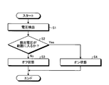
- FIG. 4 is a flowchart of the air conditioner protection method according to the first embodiment.
- a protection circuit 15 for an air conditioner includes a voltage detection circuit 1 that detects the voltage of a commercial AC power supply 10, and relays 21 and 22 that are connected between the AC power supply 10 and the control circuit 3. And comprising.
- the voltage detection circuit 1 detects the voltage of the AC power supply 10 directly from the AC power supply 10 instead of between the control circuit 3 and the relays 21 and 22. That is, the voltage of the AC power supply 10 is detected between a terminal 51 between the AC power supply 10 and the relay 21 and a terminal 52 between the AC power supply 10 and the relay 22.
- the control circuit 3 is an air conditioner control circuit, and controls an actuator of the air conditioner such as the fan motor 4.
- the control circuit 3 is protected from an abnormal voltage of the AC power supply 10 by the relays 21 and 22.
- the voltage detection circuit 1 controls whether the relays 21 and 22 are turned on or off based on the detected voltage detected. When relays 21 and 22 are on, AC power supply 10 and control circuit 3 are connected. When relays 21 and 22 are off, connection between AC power supply 10 and control circuit 3 is interrupted. Specifically, the voltage detection circuit 1 controls the terminal X1 of the relay 21 and the terminal X2 of the relay 22 to switch the relays 21 and 22 between on and off.
- the voltage detection circuit 1 detects a voltage of the AC power supply 10 and outputs a detection voltage, and determines whether or not the detection voltage is in a predetermined range.
- the determination part 12 and the control part 13 which controls the relays 21 and 22 based on the determination result of the determination part 12 are provided. Therefore, the control unit 13 controls the terminal X1 of the relay 21 and the terminal X2 of the relay 22.
- the determination unit 12 and the control unit 13 of the voltage detection circuit 1 are realized by a microcomputer 100 having a configuration as shown in FIG.
- the microcomputer 100 includes a CPU (Central Processing Unit) 101 that executes calculation and control, a RAM (Random Access Memory) 102 that the CPU 101 uses as a work area, a ROM (Read Only Memory) 103 that stores programs and data, It includes an I / O (Input / Output) 104 that is hardware for exchanging signals with the outside, and a peripheral device 105 that includes an oscillator that generates a clock.
- a CPU Central Processing Unit
- RAM Random Access Memory
- ROM Read Only Memory
- I / O Input / Output
- peripheral device 105 that includes an oscillator that generates a clock.
- the functions of the determination unit 12 and the control unit 13 in FIG. 2 are realized by the CPU 101 developing and executing software stored in the ROM 103 on the RAM 102. Accordingly, the terminal X1 of the relay 21 and the terminal X2 of the relay 22 are controlled via the I / O 104 by the CPU 101 that executes software.
- the method for realizing the voltage detection circuit 1 may not be a configuration using the microcomputer 100 as described above.
- the voltage detection unit 11 detects the voltage of the AC power supply 10 between the terminal 51 and the terminal 52 and outputs the detection voltage V (step S1).
- the determination unit 12 determines whether or not the detection voltage V detected by the voltage detection unit 11 falls within a range determined by the lower limit value V1 and the upper limit value V2 (> V1) (step S2). That is, the determination unit 12 determines whether or not V1 ⁇ V ⁇ V2 holds.
- the detected voltage V exceeds V2
- an abnormal voltage is applied to the actuator of the air conditioner such as the power supply circuit or the fan motor 4 in the control circuit 3, which may lead to the destruction thereof. Further, even when the detected voltage V is smaller than V1, malfunction may occur due to malfunction of the control circuit 3 and may lead to failure of the air conditioner.
- step S2 when the detected voltage V does not fall within the range determined by the lower limit value V1 and the upper limit value V2 (step S2: No), the control unit 13 turns off the relays 21 and 22 (step S3). Thereby, the control circuit 3 is protected from the abnormal voltage of the AC power supply 10.
- step S2 when the detected voltage V falls within the range determined by the lower limit value V1 and the upper limit value V2 (step S2: Yes), the control unit 13 turns on the relays 21 and 22 (step S4). Thereby, the control circuit 3 is energized by the AC power supply 10.
- an abnormal voltage is detected based on whether or not the voltage of the commercial power supply falls within a predetermined range, and the relay is turned on. Determine the state or off state. As a result, it is possible to prevent destruction or malfunction of the actuator, the control circuit, and the internal power supply circuit caused by the abnormal voltage.
- the relays 21 and 22 are controlled by directly measuring the voltage of the AC power supply 10 instead of the voltage applied to the control circuit 3. That is, the relays 21 and 22 are controlled based on the voltage obtained by measuring between the AC power supply 10 and the relays 21 and 22. Accordingly, when the control delay time is taken into consideration, it is possible to more reliably prevent the abnormal voltage from being applied to the control circuit 3 when the AC power supply 10 becomes an abnormal voltage.
- the protection circuit and the protection method for the air conditioner according to the first embodiment it is possible to restore the circuit immediately after protection as compared with protection using a fuse.
- the configuration described in the above embodiment shows an example of the contents of the present invention, and can be combined with another known technique, and can be combined with other configurations without departing from the gist of the present invention. It is also possible to omit or change the part.
Landscapes
- Engineering & Computer Science (AREA)
- Chemical & Material Sciences (AREA)
- Combustion & Propulsion (AREA)
- Mechanical Engineering (AREA)
- General Engineering & Computer Science (AREA)
- Air Conditioning Control Device (AREA)
- Emergency Protection Circuit Devices (AREA)
Abstract
L'invention concerne un circuit de protection d'un conditionneur d'air comportant : des relais (21, 22) connectés entre une alimentation en c.a. (10) et un circuit (3) destiné à commander le conditionneur d'air ; une unité de détection de tension destinée à détecter la tension de l'alimentation en c.a. (10) aux bornes (51, 52) entre l'alimentation en c.a. (10) et les relais (21, 22) ; une unité d'évaluation destinée à évaluer si la tension détectée par l'unité de détection de tension se trouve dans une plage définie par une limite inférieure et une limite supérieure ; et une unité de commande destinée à régler les relais (21, 22) dans un état hors tension afin de bloquer la connexion entre l'alimentation en c.a. (10) et le circuit de commande (3) lorsque la tension détectée ne se trouve pas dans ladite plage.
Priority Applications (2)
| Application Number | Priority Date | Filing Date | Title |
|---|---|---|---|
| JP2017553559A JPWO2017094151A1 (ja) | 2015-12-02 | 2015-12-02 | 空気調和機の保護回路および保護方法 |
| PCT/JP2015/083925 WO2017094151A1 (fr) | 2015-12-02 | 2015-12-02 | Circuit de protection de conditionneur d'air et procédé de protection |
Applications Claiming Priority (1)
| Application Number | Priority Date | Filing Date | Title |
|---|---|---|---|
| PCT/JP2015/083925 WO2017094151A1 (fr) | 2015-12-02 | 2015-12-02 | Circuit de protection de conditionneur d'air et procédé de protection |
Publications (1)
| Publication Number | Publication Date |
|---|---|
| WO2017094151A1 true WO2017094151A1 (fr) | 2017-06-08 |
Family
ID=58796611
Family Applications (1)
| Application Number | Title | Priority Date | Filing Date |
|---|---|---|---|
| PCT/JP2015/083925 Ceased WO2017094151A1 (fr) | 2015-12-02 | 2015-12-02 | Circuit de protection de conditionneur d'air et procédé de protection |
Country Status (2)
| Country | Link |
|---|---|
| JP (1) | JPWO2017094151A1 (fr) |
| WO (1) | WO2017094151A1 (fr) |
Citations (5)
| Publication number | Priority date | Publication date | Assignee | Title |
|---|---|---|---|---|
| US6947266B1 (en) * | 2002-02-21 | 2005-09-20 | Billingsley Richard J | Power protection device |
| WO2008146923A1 (fr) * | 2007-05-31 | 2008-12-04 | Daikin Industries, Ltd. | Climatiseur |
| JP2011117622A (ja) * | 2009-12-01 | 2011-06-16 | Panasonic Corp | 空気調和機の制御装置 |
| US20120017611A1 (en) * | 2010-07-20 | 2012-01-26 | Coffel James A | Load management aware fan control |
| US20130107401A1 (en) * | 2011-10-31 | 2013-05-02 | Trane International Inc. | Time Delay With Control Voltage Sensing |
Family Cites Families (4)
| Publication number | Priority date | Publication date | Assignee | Title |
|---|---|---|---|---|
| JPH07120045A (ja) * | 1993-10-20 | 1995-05-12 | Fujitsu General Ltd | 空気調和機の制御装置 |
| JPH11215682A (ja) * | 1998-01-26 | 1999-08-06 | Matsushita Electric Ind Co Ltd | 空気調和機の保護装置 |
| JP4151188B2 (ja) * | 2000-02-29 | 2008-09-17 | 松下電器産業株式会社 | マルチタイプ空気調和機の制御装置 |
| JP2003169481A (ja) * | 2001-11-30 | 2003-06-13 | Daikin Ind Ltd | 電源装置および空気調和機 |
-
2015
- 2015-12-02 WO PCT/JP2015/083925 patent/WO2017094151A1/fr not_active Ceased
- 2015-12-02 JP JP2017553559A patent/JPWO2017094151A1/ja active Pending
Patent Citations (5)
| Publication number | Priority date | Publication date | Assignee | Title |
|---|---|---|---|---|
| US6947266B1 (en) * | 2002-02-21 | 2005-09-20 | Billingsley Richard J | Power protection device |
| WO2008146923A1 (fr) * | 2007-05-31 | 2008-12-04 | Daikin Industries, Ltd. | Climatiseur |
| JP2011117622A (ja) * | 2009-12-01 | 2011-06-16 | Panasonic Corp | 空気調和機の制御装置 |
| US20120017611A1 (en) * | 2010-07-20 | 2012-01-26 | Coffel James A | Load management aware fan control |
| US20130107401A1 (en) * | 2011-10-31 | 2013-05-02 | Trane International Inc. | Time Delay With Control Voltage Sensing |
Also Published As
| Publication number | Publication date |
|---|---|
| JPWO2017094151A1 (ja) | 2018-03-08 |
Similar Documents
| Publication | Publication Date | Title |
|---|---|---|
| CN107943130B (zh) | 具有电流保护固态继电器的控制装置 | |
| JP6876844B2 (ja) | ソフトスタート及び保護を備える電源装置 | |
| US20080151444A1 (en) | Method and apparatus for protection against current overloads | |
| US8060321B2 (en) | System and method for detecting an electrical short across a static switch of an uninterruptible power supply | |
| US9787244B2 (en) | Air conditioner | |
| JPWO2014054349A1 (ja) | 冗長化演算処理システム | |
| JP6359957B2 (ja) | 二次破損防止機能を有するモータ駆動装置 | |
| CN104466919A (zh) | 用于电子设备的电压保护装置 | |
| JP2016123262A (ja) | インバータ用保護回路およびインバータシステム | |
| JP5511599B2 (ja) | 転流式遮断装置 | |
| US10072666B2 (en) | Hermetic compressor driving device | |
| WO2017094151A1 (fr) | Circuit de protection de conditionneur d'air et procédé de protection | |
| JP2022080747A (ja) | 保護装置、電力変換システム及び保護方法 | |
| CN104081665A (zh) | 布置在载体上的具有温度监视的电路装置和用于识别过热的方法 | |
| JP2016008932A (ja) | コントローラの接地機構 | |
| JP6091403B2 (ja) | デジタル出力装置 | |
| JP6715481B2 (ja) | 感震保護システム及びそれを備えた分電盤 | |
| JP6426208B2 (ja) | 車両制御装置 | |
| KR102919980B1 (ko) | 보호 계전기 | |
| JP2011041410A (ja) | 電子機器用過電流保護装置及び電源遮断制御方法,プログラム | |
| KR101877234B1 (ko) | 돌입전류 검지기능을 가진 교류전기철도차량용 과전류 보호 시스템 및 이를 이용한 과전류 보호 방법 | |
| JP2004357389A (ja) | 過電力保護回路および安定化電源装置ならびに過電力保護方法 | |
| JP7487455B2 (ja) | 負荷状態監視装置 | |
| US20240087790A1 (en) | Overtemperature detecting system, overtemperature protecting system, and overtemperature detecting method | |
| EP3399533B1 (fr) | Procédé et dispositif de commande d'ouverture/fermeture de disjoncteur |
Legal Events
| Date | Code | Title | Description |
|---|---|---|---|
| 121 | Ep: the epo has been informed by wipo that ep was designated in this application |
Ref document number: 15909781 Country of ref document: EP Kind code of ref document: A1 |
|
| ENP | Entry into the national phase |
Ref document number: 2017553559 Country of ref document: JP Kind code of ref document: A |
|
| NENP | Non-entry into the national phase |
Ref country code: DE |
|
| 122 | Ep: pct application non-entry in european phase |
Ref document number: 15909781 Country of ref document: EP Kind code of ref document: A1 |