WO2017104049A1 - Échangeur de chaleur, climatiseur comportant ledit échangeur de chaleur et procédé de production d'échangeur de chaleur - Google Patents
Échangeur de chaleur, climatiseur comportant ledit échangeur de chaleur et procédé de production d'échangeur de chaleur Download PDFInfo
- Publication number
- WO2017104049A1 WO2017104049A1 PCT/JP2015/085361 JP2015085361W WO2017104049A1 WO 2017104049 A1 WO2017104049 A1 WO 2017104049A1 JP 2015085361 W JP2015085361 W JP 2015085361W WO 2017104049 A1 WO2017104049 A1 WO 2017104049A1
- Authority
- WO
- WIPO (PCT)
- Prior art keywords
- flat
- sectional shape
- opening
- central axis
- heat exchanger
- Prior art date
- Legal status (The legal status is an assumption and is not a legal conclusion. Google has not performed a legal analysis and makes no representation as to the accuracy of the status listed.)
- Ceased
Links
Images


Classifications
-
- F—MECHANICAL ENGINEERING; LIGHTING; HEATING; WEAPONS; BLASTING
- F28—HEAT EXCHANGE IN GENERAL
- F28D—HEAT-EXCHANGE APPARATUS, NOT PROVIDED FOR IN ANOTHER SUBCLASS, IN WHICH THE HEAT-EXCHANGE MEDIA DO NOT COME INTO DIRECT CONTACT
- F28D1/00—Heat-exchange apparatus having stationary conduit assemblies for one heat-exchange medium only, the media being in contact with different sides of the conduit wall, in which the other heat-exchange medium is a large body of fluid, e.g. domestic or motor car radiators
- F28D1/02—Heat-exchange apparatus having stationary conduit assemblies for one heat-exchange medium only, the media being in contact with different sides of the conduit wall, in which the other heat-exchange medium is a large body of fluid, e.g. domestic or motor car radiators with heat-exchange conduits immersed in the body of fluid
- F28D1/04—Heat-exchange apparatus having stationary conduit assemblies for one heat-exchange medium only, the media being in contact with different sides of the conduit wall, in which the other heat-exchange medium is a large body of fluid, e.g. domestic or motor car radiators with heat-exchange conduits immersed in the body of fluid with tubular conduits
- F28D1/053—Heat-exchange apparatus having stationary conduit assemblies for one heat-exchange medium only, the media being in contact with different sides of the conduit wall, in which the other heat-exchange medium is a large body of fluid, e.g. domestic or motor car radiators with heat-exchange conduits immersed in the body of fluid with tubular conduits the conduits being straight
-
- F—MECHANICAL ENGINEERING; LIGHTING; HEATING; WEAPONS; BLASTING
- F28—HEAT EXCHANGE IN GENERAL
- F28F—DETAILS OF HEAT-EXCHANGE AND HEAT-TRANSFER APPARATUS, OF GENERAL APPLICATION
- F28F1/00—Tubular elements; Assemblies of tubular elements
- F28F1/10—Tubular elements and assemblies thereof with means for increasing heat-transfer area, e.g. with fins, with projections, with recesses
- F28F1/12—Tubular elements and assemblies thereof with means for increasing heat-transfer area, e.g. with fins, with projections, with recesses the means being only outside the tubular element
- F28F1/24—Tubular elements and assemblies thereof with means for increasing heat-transfer area, e.g. with fins, with projections, with recesses the means being only outside the tubular element and extending transversely
- F28F1/30—Tubular elements and assemblies thereof with means for increasing heat-transfer area, e.g. with fins, with projections, with recesses the means being only outside the tubular element and extending transversely the means being attachable to the element
Definitions
- the present invention relates to a heat exchanger, an air conditioner including the heat exchanger, and a method for manufacturing the heat exchanger, and in particular, a heat exchanger to which a flat tube is applied as a heat transfer tube, and an air conditioner including the heat exchanger. And a method of manufacturing the heat exchanger.
- the heat exchanger of an outdoor unit used for an air conditioner includes a heat exchanger in which a heat transfer tube through which a refrigerant flows is arranged so as to penetrate plate-like fins arranged at intervals.
- a heat exchanger is called a finned tube heat exchanger.
- a heat exchanger in which a flat tube having a flat cross-sectional shape with a flat cross-sectional shape is used as a heat transfer tube so that heat exchange is efficiently performed.
- a plurality of flat tubes in which the long diameter of the flat cross-sectional shape is arranged along the air flow direction are arranged at a distance from each other in the short-diameter direction of the flat cross-sectional shape.
- a plurality of other flat tubes (second row) are arranged at a distance in the long diameter direction of the flat cross-sectional shape.
- Each of the flat tubes in the first row and each of the corresponding flat tubes in the second row are connected by a joint portion.
- a heat exchanger using a flat tube is required to more efficiently perform heat exchange between refrigerant and air.
- the present invention has been made as part of such development, and one object is to provide a heat exchanger that can further improve heat exchange, and the other object is such heat exchange. It is providing the air conditioner provided with the apparatus, and the other objective is to provide the manufacturing method of such a heat exchanger.
- the heat exchanger according to the present invention includes a first flat tube, a second flat tube, and a joint portion.
- the first flat tube has a flat cross-sectional shape having a major axis and a minor axis.
- the second flat tube has a flat cross-sectional shape and is spaced from the first flat tube in the direction of the major axis.
- the joint portion connects the first flat tube and the second flat tube.
- the joint portion includes a first opening, a second opening, and a flow path.
- the first opening has a first cross-sectional shape corresponding to the flat cross-sectional shape and communicates with the first flat tube.
- the second opening is spaced from the first opening in the direction of the major axis, has a second cross-sectional shape corresponding to the flat cross-sectional shape, and communicates with the second flat tube.
- the flow path has a circular cross-sectional shape, is connected to the first opening and the second opening, and allows the first opening and the second opening to communicate with each other.
- An axis that passes through the center of the second cross-sectional shape at the first position where the flow path and the second opening are connected and is parallel to the direction in which the second flat tube extends is defined as the first central axis
- the flow path and the first An axis parallel to the direction in which the first flat tube extends through the center of the circular cross-sectional shape at the second position where the opening is connected is the second central axis
- the center of the first cross-sectional shape at the second position is The axis parallel to the direction in which the first flat tube extends is taken as the third central axis. Then, the first distance between the first central axis and the second central axis is longer than the second distance between the first central axis and the third central axis.
- the air conditioner which concerns on this invention is an air conditioner provided with the heat exchanger mentioned above.
- the manufacturing method of the heat exchanger according to the present invention includes the following steps. A plurality of first flat tubes each having a flat cross-sectional shape having a long diameter and a short diameter are prepared, and a plurality of second flat tubes each having a flat cross-sectional shape are prepared. Each of the plurality of first flat tubes is disposed at a distance from each other in the minor axis direction. Each of the plurality of second flat tubes is arranged with a distance in the direction of the short diameter, and is arranged with a distance in the direction of the long diameter with respect to each of the plurality of first flat tubes.
- a joint portion having a flow path having a circular cross-sectional shape is formed.
- each of the plurality of first flat tubes and the plurality of second flat tubes disposed at a distance in the major axis direction with respect to each of the plurality of first flat tubes. Connect joints to each of the tubes.
- the assembled plurality of first flat tubes, the plurality of second flat tubes, and the plurality of joint portions are brazed.
- an axis parallel to the direction in which the second flat tube extends passes through the center of the second cross-sectional shape at the first position where the flow path and the second opening are connected.
- An axis that passes through the center of the circular cross-sectional shape at the second position where the flow path and the first opening are connected, and that is parallel to the direction in which the first flat tube extends, is the second central axis, and the second position If the third central axis is an axis that passes through the center of the first cross-sectional shape and is parallel to the direction in which the first flat tube extends, the first distance between the first central axis and the second central axis is: It is formed to be longer than the second distance between the first central axis and the third central axis.
- the first opening, the second opening, and the flow path are formed in the joint so that the first distance is longer than the second distance. Therefore, heat exchange can be efficiently performed with respect to any one of the cooling operation and the heating operation.
- the air conditioner according to the present invention energy efficiency can be increased. According to the manufacturing method of the heat exchanger which concerns on this invention, the heat exchanger provided with the joint part in which heat exchange is performed efficiently can be manufactured.
- FIG. 5 is a partially enlarged cross-sectional view taken along a cross-sectional line VV shown in FIG. 4 in the embodiment.
- FIG. 6 is a partially enlarged cross-sectional view taken along a cross-sectional line VI-VI shown in FIG. 4 in the same embodiment.
- FIG. 10 is an enlarged sectional view taken along a sectional line XX shown in FIG. 9 in the embodiment.
- FIG. 13 is an enlarged cross-sectional view taken along a cross-sectional line XIII-XIII shown in FIG. 12 in the same embodiment. It is a perspective view which shows 1 process of the manufacturing method of the heat exchanger which concerns on Embodiment 2 of this invention.
- FIG. 15 is a perspective view showing a step performed after the step shown in FIG. 14 in the same embodiment.
- FIG. 16 is a perspective view showing a step performed after the step shown in FIG. 15 in the same embodiment.
- FIG. 17 is a partial perspective view showing a process performed after the process shown in FIG. 16 in the same embodiment.
- FIG. 18 is a partial perspective view illustrating a process performed after the process illustrated in FIG. 17 in the embodiment.
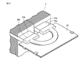
- FIG. 19 is a perspective view showing a step performed after the step shown in FIG. 18 in the same embodiment.
- it is a partial expansion perspective view which shows 1 process of the manufacturing method which concerns on a modification.
- FIG. 21 is a partially enlarged perspective view showing a process performed after the process shown in FIG. 20 in the same embodiment.
- FIG. 22 is a perspective view showing a step performed after the step shown in FIG. 21 in the same embodiment.
- FIG. 24 is a partially enlarged perspective view showing a process performed after the process shown in FIG. 23 in the embodiment.
- the refrigerant circuit of the air conditioner 1 includes a compressor 3, a condensation heat exchanger 7 (5), a main throttle device 11, an evaporating heat exchanger 9 (5), blowers 8a and 10a, and a motor 8b. 10b.
- the condensation heat exchanger 7 becomes a heat exchanger 5 mounted on the outdoor unit
- the evaporating heat exchanger 9 becomes a heat exchanger mounted on the indoor unit.
- the evaporative heat exchanger 9 becomes the heat exchanger 5 mounted on the outdoor unit, and the condensing heat exchanger 7 becomes the heat exchanger mounted on the indoor unit.
- a refrigerant such as R410A, R32, HFO-1234yf, or the like is used as the refrigerant.
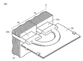
- the structure of the heat exchanger 5 mounted on the outdoor unit as the condensation heat exchanger 7 or the evaporative heat exchanger 9 will be described.
- the plurality of plate-like fins 21 that are spaced apart from each other have a flat cross-sectional shape (see FIG. 17) having a major axis LR and a minor axis SR as heat transfer tubes.
- a plurality of first flat tubes 23a and second flat tubes 23b are disposed so as to penetrate from one to the other.
- Each of the plurality of first flat tubes 23a is disposed at a distance from each other in the minor axis direction.
- the plurality of first flat tubes 23a become the first flat tubes 23a in the first row 5a.
- each of the plurality of second flat tubes 23b is spaced apart from each other in the minor axis direction, and is disposed at a distance in the major axis direction from each of the plurality of first flat tubes 23a.
- the plurality of second flat tubes 23b become the second flat tubes 23b in the second row 5b.
- the blowers 8a and 10a are arranged so as to face the second flat tubes 23b in the second row.
- the first flat tubes 23a in the first row 5a are arranged on the windward side.
- the second flat tubes 23b in the second row 5b are arranged on the leeward side.
- Each of the plurality of first flat tubes 23 a protruding from one of the plurality of fins 21 and each of the corresponding plurality of second flat tubes 23 b are connected by a joint portion 25.
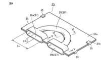
- the joint portion 25 includes a first opening 26 a, a second opening 26 b, and a flow path 28.
- Each of the first opening 26a and the second opening 26b is a flat type having a long diameter LL and a short diameter LS corresponding to the flat cross-sectional shapes of the first flat tube 23a and the second flat tube 23b (see FIG. 17). It has a cross-sectional shape 27.
- the flow path 28 has a circular cross-sectional shape 29 and is formed so as to draw a substantially semicircle.
- the first opening 26a is connected to the first flat tube 23a and communicates with the first flat tube 23a.
- the second opening 26b is connected to the second flat tube 23b and communicates with the second flat tube 23b.
- the flow path 28 is connected to the first opening 26a and the second opening 26b, and allows the first opening 26a and the second opening 26b to communicate with each other.
- the joint portion 25 is formed by joining (caulking) two pressed aluminum plates to each other.
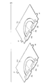
- the first flat tube 23 a (the first flat tube 23 a) is passed through the center MC of the circular cross-sectional shape 29 at the position where the flow path 28 and the first opening 26 a (second opening 26 b) are connected.
- An axis parallel to the direction in which the 2 flat tubes 23b) extend is defined as a central axis CC.
- an axis parallel to the direction in which the first flat tube 23a (second flat tube 23b) extends through the center MF of the flat cross-sectional shape 27 at that position is defined as a central axis CF.
- the center MF of the flat cross-sectional shape 27 refers to an intersection where the vertical bisector of the long diameter LL (see FIG. 4) and the vertical bisector of the short diameter LS (see FIG. 4) intersect. It is not intended to be a geometrically exact intersection and includes manufacturing errors. The same applies to the center MC of the circular cross-sectional shape 29.
- the distance between the central axis CF on the second opening 26b side and the central axis CC on the first opening 26a is equal to the central axis CF on the second opening 26b side and the first opening. It is longer than the distance between the central axis CF on the part 26a side.
- the distance between the central axis CF on the first opening 26a side and the central axis CC on the second opening 26b side is equal to the central axis CF on the first opening 26a side and the central axis on the second opening 26b side. Longer than the distance to the CF.
- the center axis CC is located on the windward side than the center axis CF.
- the central axis CC is located on the leeward side with respect to the central axis CF.
- the distribution header 15 is disposed on the leeward side (first row 5a side), and the gas header 13 is disposed on the leeward side (second row 5b side).
- the heat exchanger 5 according to Embodiment 1 is configured as described above.
- the cooling operation the high-temperature and high-pressure gas refrigerant compressed by the compressor is sent to the condensation heat exchanger 7.
- the high-temperature and high-pressure gas refrigerant is liquefied while dissipating heat to the surroundings, and becomes a low-temperature and high-pressure liquid refrigerant.
- the low-temperature and high-pressure liquid refrigerant is reduced in pressure by the main throttle device 11 and becomes a low-temperature and low-pressure liquid refrigerant.
- the low-temperature and low-pressure liquid refrigerant is sent to the evaporative heat exchanger 9.
- the low-temperature and low-pressure liquid refrigerant is vaporized while taking away the surrounding heat, and becomes a low-pressure gas refrigerant.
- the low-pressure gas refrigerant is sent to the compressor and becomes a high-temperature and high-pressure gas refrigerant. Thereafter, this cycle is repeated.
- the heat exchanger 5 is mounted on the outdoor unit as the condensation heat exchanger 7.
- the flow of the refrigerant in the heat exchanger 5 (condensing heat exchanger 7) will be described.
- the air passes through the heat exchanger 5 from the first row 5a side to the second row 5b side as shown by the arrow YW. Will flow.
- the high-temperature and high-pressure gas refrigerant sent from the compressor firstly connects the second flat tubes 23b in the second row 5b located on the leeward side from the side where the gas header 13 is arranged as shown by the arrow YC. It flows toward the side where 25 is arranged. In the joint portion 25, the refrigerant flowing through the second flat tube 23b passes through the second opening 26b, the flow path 28, and the first opening 26a, and the first flat tube 23a in the first row 5a located on the windward side. Sent to.
- the refrigerant sent to the first flat tube 23a flows through the first flat tube 23a toward the side where the distribution header 15 is disposed, as indicated by an arrow YC. While the high-temperature and high-pressure gas refrigerant flows through the second flat tube 23b and the first flat tube 23a, heat exchange is performed with the air passing through the heat exchanger 5 to become a low-temperature and high-pressure liquid refrigerant.
- the refrigerant flow in the joint portion 25 will be described.
- the high-temperature and high-pressure gas refrigerant is gradually condensed and liquefied while flowing through the second flat tube 23 b on the leeward side, and the gas refrigerant and the liquid are supplied to the second opening 26 b of the joint portion 25.
- a two-phase refrigerant flows into the refrigerant.
- the refrigerant that has flowed into the second opening 26b flows through the flow path 28 and into the first opening 26a.
- the liquid refrigerant out of the two-phase state refrigerant once flows into the windward side of the first opening 26a due to inertial force, and further flows on the inner wall surface of the first opening 26a due to the inertial force. Thus, it flows into the leeward side of the first opening 26a (see the arrow indicating the flow). For this reason, the distribution of the liquid refrigerant 41 immediately before flowing into the first flat tube 23a is biased toward the leeward side. As the liquid refrigerant 41 is biased toward the leeward side, the gas refrigerant is unevenly distributed on the windward side.
- the gas refrigerant is mainly distributed on the leeward side and the liquid refrigerant 41 is mainly distributed on the leeward side, and the refrigerant is supplied to the first flat tube 23a provided with the refrigerant passage 24. Flows in. Since the heat flow rate on the windward side is larger than the heat flow rate on the leeward side, the gas refrigerant distributed unevenly on the windward side is efficiently condensed and liquefied while flowing through the first flat tube 23a. Thereby, at the distribution header 15 side (exit) of the heat exchanger 5, the dryness of the refrigerant becomes substantially uniform in the direction of the long diameter of the first flat tube 23a. Thus, the low-temperature and high-pressure liquid refrigerant condensed and liquefied is sent out from the heat exchanger 5.
- the flow of the refrigerant in the refrigerant circuit in the heating operation is as described for the cooling operation.
- the heat exchanger 5 is mounted on the outdoor unit as the evaporating heat exchanger 9.
- the distribution header 15 is arranged in the first flat tubes 23a in the first row 5a located on the windward side as indicated by the arrow YH. It flows from the side toward the side where the joint part 25 is disposed. In the joint portion 25, the refrigerant flowing through the first flat tube 23a passes through the first opening 26a, the flow path 28, and the second opening 26b, and the second flat tubes 23b in the second row 5b located on the leeward side. Sent to.
- the refrigerant sent to the second flat tube 23b flows through the second flat tube 23b toward the side where the gas header 13 is disposed, as indicated by an arrow YH. While the low-temperature and low-pressure liquid refrigerant flows through the first flat tube 23a and the second flat tube 23b, heat exchange is performed with the air passing through the heat exchanger 5 to become a low-pressure gas refrigerant.
- the low-temperature and low-pressure liquid refrigerant gradually evaporates and vaporizes while flowing through the first flat tube 23a on the windward side, and gas refrigerant and liquid are supplied to the first opening 26a of the joint portion 25.
- a two-phase refrigerant flows into the refrigerant.
- the refrigerant that has flowed into the first opening 26a flows through the flow path 28 and into the second opening 26b.
- the liquid refrigerant out of the two-phase state refrigerant once flows into the leeward side of the second opening 26b due to the inertial force, and further flows along the inner wall surface of the second opening 26b due to the inertial force. Thus, it flows into the windward side of the second opening 26b (see the arrow indicating the flow). For this reason, the distribution of the liquid refrigerant 41 immediately before flowing into the second flat tube 23b is a distribution biased toward the windward side. As the liquid refrigerant 41 is biased toward the windward side, the gas refrigerant is unevenly distributed on the leeward side.
- the liquid refrigerant 41 is mainly distributed on the leeward side, and the gas refrigerant is mainly distributed on the leeward side, and the refrigerant is supplied to the second flat tube 23b provided with the refrigerant passage 24. Flows in. Since the heat flow rate on the windward side is larger than the heat flow rate on the leeward side, the liquid refrigerant 41 distributed unevenly on the windward side is efficiently evaporated and vaporized while flowing through the second flat tube 23b. Thereby, on the gas header 13 side (exit) of the heat exchanger 5, the dryness of the refrigerant becomes substantially uniform in the direction of the major axis of the second flat tube 23b. Thus, the low-pressure gas refrigerant evaporated and vaporized is sent out from the heat exchanger 5.
- the central axis CC of the flow path 28 is located on the windward side with respect to the central axis CF of the first opening 26a. Therefore, when the heat exchanger 5 is used as a condensation heat exchanger (cooling operation), the refrigerant passes from the second flat tube 23b on the leeward side through the second opening 26b and the flow path 28 of the joint portion 25. When flowing into the first opening 26a, the liquid refrigerant can be biased to the leeward side by inertial force.
- the liquid refrigerant flows into the first flat tube 23a on the leeward side in a state where the liquid refrigerant is biased toward the leeward side and the gas refrigerant is biased toward the windward side.
- the gas refrigerant can be efficiently condensed and liquefied.
- heat exchange is performed more efficiently than when the gas refrigerant (or liquid refrigerant) flows into the first flat tube 23a with a substantially uniform distribution in the direction of the long diameter of the first flat tube 23a,
- the heat exchange performance as a heat exchanger can be improved.
- the heat exchange performance is the product of the heat transfer area and the heat passage rate, and the higher this value, the higher the heat exchange performance.
- the central axis CC of the flow path 28 is located on the leeward side with respect to the central axis CF of the second opening 26b.
- the liquid refrigerant flows into the second flat tube 23b on the leeward side in a state where the liquid refrigerant is biased toward the leeward side and the gas refrigerant is biased toward the leeward side.
- the liquid refrigerant can be efficiently evaporated and vaporized.
- the liquid refrigerant (or gas refrigerant) exchanges heat more efficiently than when flowing into the second flat tube 23b with a substantially uniform distribution in the direction of the major axis of the second flat tube 23b, The heat exchange performance as a heat exchanger can be improved.
- Heating energy efficiency condensation heat exchanger (indoor) capacity (watts) / total input (watts) Represented by
- Cooling energy efficiency evaporative heat exchanger (indoor) capacity (watts) / total input (watts) Represented by
- Embodiment 2 Here, an example of the manufacturing method of the heat exchanger provided with the joint part described in the first embodiment will be described.
- two aluminum plates 31a and 31b are prepared as metal plates (plate-like bodies) cut into desired dimensions.
- Each of the aluminum plates 31a and 31b is formed with a protruding portion 32 serving as a crimped portion.
- the first recess 33a is formed in the aluminum plate 31a
- the second recess 33b is formed in the aluminum plate 31b.
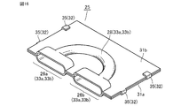
- the first recess 33a and the second recess 33b are formed in a shape that becomes the first opening 26a, the second opening 26b, and the flow path 28 in a state where the aluminum plate 31a and the aluminum plate 31b are combined. (See FIG. 16). That is, as shown in FIG. 7, the first concave portion 33a and the second concave portion 33b are formed so that the central axis CC and the central axis CF are shifted from each other in the direction of the long diameter LL (see FIG. 4). become.
- the aluminum plate 31a and the aluminum plate 31b are aligned, and the protruding portion 32 is bent and caulked to each other (caulking portion). 35).
- the first opening 26a, the flow path 28, and the second opening 26b are formed by the first recess 33a and the second recess 33b facing each other.
- the joint portion 25 is formed.
- the joint portion 25 is connected to the first flat tube and the second flat tube.
- the first flat tube 23a is fitted with the first opening 26a with respect to the first flat tube 23a and the second flat tube 23b that penetrate the plurality of fins 21 and protrude from one side, respectively.
- the joint portion 25 is pushed toward the first flat tube 23a (second flat tube 23b) in a state where the second opening 26b is aligned with the second flat tube 23b.
- the joint portion 25 is connected to the first flat tube 23a and the second flat tube 23b, and the first flat tube 23a and the second flat tube 23b are connected.
- each of the plurality of first flat tubes 23a penetrating the plurality of fins 21 and projecting from one side, and each of the corresponding plurality of second flat tubes 23b, respectively. are connected by the joint portion 25.
- flux is applied to the plurality of fins 21, the first flat tube 23a, the second flat tube 23b, and the joint portion 25 (assembly) assembled by, for example, a spray method.
- the assembly to which the flux is applied is placed in a furnace (not shown).
- brazing is performed by performing a heat treatment on the assembly under a predetermined temperature condition.
- the heat exchanger 5 provided with the joint portion 25 is completed.
- the outdoor unit of an air conditioner is completed by assembling the completed heat exchanger 5 in a predetermined housing (see FIG. 2).
- the distance between the central axis CF on the second opening 26b side and the central axis CC on the first opening 26a side is set on the second opening 26b side. It is longer than the distance between the central axis CF and the central axis CF on the first opening 26a side.
- the distance between the central axis CF on the first opening 26a side and the central axis CC on the second opening 26b side is equal to the central axis CF on the first opening 26a side and the central axis on the second opening 26b side. Longer than the distance to the CF. That is, the central axis CC and the central axis CF are shifted from each other in the direction of the major axis LL (see FIG. 4).
- the joint portion 25 having the first opening portion 26a, the flow path 28 and the second opening portion 26b is formed by pressing the two aluminum plates 31a and 31b. Formed (see FIGS. 14 to 16). Thereby, the 1st recessed part 33a and the 2nd recessed part 33b used as the 1st opening part 26a, the flow path 28, and the 2nd opening part 26b which have the said arrangement
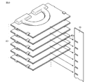
- a holding member 43 that holds the plurality of joint portions 25 at intervals in the minor axis direction is prepared.
- a plurality of slits 43 a are formed in the holding member 43 at intervals in the longitudinal direction.
- the joint portion 25 is fitted into each of the plurality of slits 43a.
- the plurality of joint portions 25 are held by the holding member 43 while being spaced apart from each other.
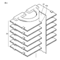
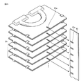
- the plurality of held joint portions 25 are collectively connected to the corresponding first flat tube 23a and second flat tube 23b.
- the plurality of joint portions 25 are collectively handled as compared with a case where the plurality of joint portions 25 are connected one by one to the corresponding first flat tube 23a and second flat tube 23b. It can connect to the 1st flat tube 23a and the 2nd flat tube 23b, and efficiency improvement of the assembly operation of the heat exchanger 5 can be achieved.
- the joint portion 25 is fitted into the slit 43a of the holding member 43, and the holding member 43 is fitted into the slit 25a of the joint portion 25, so that the plurality of joint portions are more firmly secured by the holding member. Retained. Thereby, when connecting the some joint part 25 to a 1st flat tube and a 2nd flat tube, positioning becomes easy.
- the case where the plurality of joint portions 25 are held by one holding member 43 has been described as an example.
- two or more holding members may be used.
- positioning is performed when connecting the plurality of joint portions 25 to the first flat tube and the second flat tube. Is even easier.
- first opening, the flow path, and the second opening can be formed with an arrangement relationship in which the central axis CC and the central axis CF are shifted from each other in the direction of the long diameter LL.
- the method is not limited to the press working method.
- the first opening, the flow path, and the second opening may be connected by brazing or the like so that the arrangement relationship is established. Good.
- the heat exchanger 5 provided in the outdoor unit has been described as an example of the heat exchanger 5 including the joint portion 25, it can also be applied as a heat exchanger mounted in the indoor unit.
- refrigeration oils such as mineral oils, alkylbenzene oils, ester oils, ether oils, fluorine oils, etc. can be used as the refrigeration oils, regardless of whether the refrigerant or the refrigeration oil is insoluble or insoluble. The effect by can be acquired.
- the present invention can also be applied to heat exchange between the refrigerant and a gas other than air, a liquid, or a gas-liquid mixed flow.
- the heat exchanger may be a finless heat exchanger (not shown) that does not include fins.
- a finless heat exchanger when connecting the joint portion to the first flat tube and the second flat tube, the first flat tube and the second flat tube are connected to a predetermined position by a holding member or the like (not shown). What is necessary is just to connect a joint part in the state hold
- the present invention is effectively used in a heat exchanger, an air conditioner, a heat pump device, etc. to which a flat tube is applied as a heat transfer tube of an air conditioner.
Landscapes
- Engineering & Computer Science (AREA)
- Physics & Mathematics (AREA)
- Thermal Sciences (AREA)
- Mechanical Engineering (AREA)
- General Engineering & Computer Science (AREA)
- Geometry (AREA)
- Heat-Exchange Devices With Radiators And Conduit Assemblies (AREA)
- Details Of Heat-Exchange And Heat-Transfer (AREA)
- Other Air-Conditioning Systems (AREA)
Abstract
La présente invention concerne un échangeur de chaleur (5) comprenant une partie de joint (25) reliant un premier tube plat (23a) d'une première rangée (5a) et un second tube plat (23b) d'une seconde rangée (5b), la partie de joint comportant une première section ouverte (26a), une seconde section ouverte (26b) et un circuit d'écoulement (28). Dans la partie de joint (25), la distance entre un axe central (CF) du côté de la seconde section ouverte (26b) et un axe central (CC) du côté de la première section ouverte (26a) est plus longue que la distance entre l'axe central (CF) du côté de la seconde section ouverte (26b) et l'axe central (CF) du côté de la première section ouverte (26a). En outre, la distance entre l'axe central (CF) du côté de la première section ouverte (26a) et l'axe central (CC) du côté de la seconde section ouverte (26b) est plus longue que la distance entre l'axe central (CF) du côté de la première section ouverte (26a) et l'axe central (CF) de la seconde section ouverte (26b).
Priority Applications (2)
| Application Number | Priority Date | Filing Date | Title |
|---|---|---|---|
| PCT/JP2015/085361 WO2017104049A1 (fr) | 2015-12-17 | 2015-12-17 | Échangeur de chaleur, climatiseur comportant ledit échangeur de chaleur et procédé de production d'échangeur de chaleur |
| JP2017556276A JP6440867B2 (ja) | 2015-12-17 | 2015-12-17 | 熱交換器およびそれを備えた空気調和機ならびに熱交換器の製造方法 |
Applications Claiming Priority (1)
| Application Number | Priority Date | Filing Date | Title |
|---|---|---|---|
| PCT/JP2015/085361 WO2017104049A1 (fr) | 2015-12-17 | 2015-12-17 | Échangeur de chaleur, climatiseur comportant ledit échangeur de chaleur et procédé de production d'échangeur de chaleur |
Publications (1)
| Publication Number | Publication Date |
|---|---|
| WO2017104049A1 true WO2017104049A1 (fr) | 2017-06-22 |
Family
ID=59056120
Family Applications (1)
| Application Number | Title | Priority Date | Filing Date |
|---|---|---|---|
| PCT/JP2015/085361 Ceased WO2017104049A1 (fr) | 2015-12-17 | 2015-12-17 | Échangeur de chaleur, climatiseur comportant ledit échangeur de chaleur et procédé de production d'échangeur de chaleur |
Country Status (2)
| Country | Link |
|---|---|
| JP (1) | JP6440867B2 (fr) |
| WO (1) | WO2017104049A1 (fr) |
Cited By (1)
| Publication number | Priority date | Publication date | Assignee | Title |
|---|---|---|---|---|
| JP2019132512A (ja) * | 2018-01-31 | 2019-08-08 | ダイキン工業株式会社 | 冷凍装置 |
Citations (5)
| Publication number | Priority date | Publication date | Assignee | Title |
|---|---|---|---|---|
| JPS597887A (ja) * | 1982-07-06 | 1984-01-17 | Mitsubishi Heavy Ind Ltd | 蛇管形伝熱管の製作方法 |
| JPS6281876U (fr) * | 1985-10-31 | 1987-05-25 | ||
| JP2008122058A (ja) * | 2006-10-17 | 2008-05-29 | Alps Electric Co Ltd | ラジエータ及び冷却システム |
| JP2010185614A (ja) * | 2009-02-12 | 2010-08-26 | Mitsubishi Electric Corp | 扁平管継手 |
| JP2014119212A (ja) * | 2012-12-18 | 2014-06-30 | Nisshin Steel Co Ltd | 熱交換器 |
Family Cites Families (7)
| Publication number | Priority date | Publication date | Assignee | Title |
|---|---|---|---|---|
| FR1050082A (fr) * | 1952-02-01 | 1954-01-05 | Radiateur de chauffage | |
| JPS577993Y2 (fr) * | 1978-04-01 | 1982-02-16 | ||
| IT1234289B (it) * | 1989-06-14 | 1992-05-14 | Piemontese Radiatori | Perfezionamenti apportati ad uno scambiatore di calore a tubi appiattiti |
| RO120359B1 (ro) * | 1998-06-12 | 2005-12-30 | S.C. Romradiatoare S.A. | Element radiant pentru schimbătoare de căldură şi procedeu de realizare a acestora |
| CN104121800B (zh) * | 2013-04-27 | 2017-09-26 | 杭州三花微通道换热器有限公司 | 流通管接头及具有该流通管接头的换热器 |
| JP6207624B2 (ja) * | 2013-10-29 | 2017-10-04 | 三菱電機株式会社 | 熱交換器、及び、空気調和装置 |
| JP6355473B2 (ja) * | 2014-08-07 | 2018-07-11 | 三菱電機株式会社 | 熱交換器 |
-
2015
- 2015-12-17 WO PCT/JP2015/085361 patent/WO2017104049A1/fr not_active Ceased
- 2015-12-17 JP JP2017556276A patent/JP6440867B2/ja active Active
Patent Citations (5)
| Publication number | Priority date | Publication date | Assignee | Title |
|---|---|---|---|---|
| JPS597887A (ja) * | 1982-07-06 | 1984-01-17 | Mitsubishi Heavy Ind Ltd | 蛇管形伝熱管の製作方法 |
| JPS6281876U (fr) * | 1985-10-31 | 1987-05-25 | ||
| JP2008122058A (ja) * | 2006-10-17 | 2008-05-29 | Alps Electric Co Ltd | ラジエータ及び冷却システム |
| JP2010185614A (ja) * | 2009-02-12 | 2010-08-26 | Mitsubishi Electric Corp | 扁平管継手 |
| JP2014119212A (ja) * | 2012-12-18 | 2014-06-30 | Nisshin Steel Co Ltd | 熱交換器 |
Cited By (1)
| Publication number | Priority date | Publication date | Assignee | Title |
|---|---|---|---|---|
| JP2019132512A (ja) * | 2018-01-31 | 2019-08-08 | ダイキン工業株式会社 | 冷凍装置 |
Also Published As
| Publication number | Publication date |
|---|---|
| JP6440867B2 (ja) | 2018-12-19 |
| JPWO2017104049A1 (ja) | 2018-03-29 |
Similar Documents
| Publication | Publication Date | Title |
|---|---|---|
| US9322602B2 (en) | Heat exchanger having a plurality of plate-like fins and a plurality of flat-shaped heat transfer pipes orthogonal to the plate-like fins | |
| CN103123185B (zh) | 热交换器及其制造方法 | |
| JP2009281693A (ja) | 熱交換器、その製造方法及びこの熱交換器を用いた空調冷凍装置 | |
| CN106482568B (zh) | 用于换热器的换热管、换热器及其装配方法 | |
| JP6765528B2 (ja) | 熱交換器、冷凍サイクル装置および空気調和機 | |
| JP3934631B2 (ja) | 熱交換器用エンドプレートと、これを備える熱交換器及びその作製方法 | |
| US10941989B2 (en) | Air conditioner and method of manufacturing the same | |
| JP2014074513A (ja) | フィンチューブ熱交換器、ヒートポンプ装置及び伝熱フィン | |
| JP2018112378A (ja) | 伝熱管、熱交換器、および熱交換器の製造方法 | |
| JP2010249374A (ja) | フィンチューブ型熱交換器並びに空調冷凍装置 | |
| JP7118279B2 (ja) | 熱交換器、その製造方法および空気調和装置 | |
| JP6880206B2 (ja) | 熱交換器の製造方法 | |
| JP6440867B2 (ja) | 熱交換器およびそれを備えた空気調和機ならびに熱交換器の製造方法 | |
| KR20130084179A (ko) | 열교환기 | |
| US12339070B2 (en) | Heat exchanger | |
| JP6826133B2 (ja) | 熱交換器及び冷凍サイクル装置 | |
| JP6455103B2 (ja) | 熱交換器 | |
| JP6493575B1 (ja) | 冷凍装置 | |
| CN106482566B (zh) | 用于换热器的换热管、换热器及其装配方法 | |
| KR20120051450A (ko) | 냉장고용 응축기 및 그 제조방법 | |
| JP6797304B2 (ja) | 熱交換器及び空気調和機 | |
| JP5404729B2 (ja) | 熱交換器及び冷凍サイクル装置 | |
| US20140083664A1 (en) | Heat exchanger | |
| JPWO2018096666A1 (ja) | 熱交換器および冷凍サイクル装置並びに熱交換器の製造方法 | |
| KR20170042138A (ko) | 다열 열교환기 |
Legal Events
| Date | Code | Title | Description |
|---|---|---|---|
| 121 | Ep: the epo has been informed by wipo that ep was designated in this application |
Ref document number: 15910739 Country of ref document: EP Kind code of ref document: A1 |
|
| ENP | Entry into the national phase |
Ref document number: 2017556276 Country of ref document: JP Kind code of ref document: A |
|
| NENP | Non-entry into the national phase |
Ref country code: DE |
|
| 122 | Ep: pct application non-entry in european phase |
Ref document number: 15910739 Country of ref document: EP Kind code of ref document: A1 |