WO2017104071A1 - Dispositif de commande d'ascenseur - Google Patents
Dispositif de commande d'ascenseur Download PDFInfo
- Publication number
- WO2017104071A1 WO2017104071A1 PCT/JP2015/085498 JP2015085498W WO2017104071A1 WO 2017104071 A1 WO2017104071 A1 WO 2017104071A1 JP 2015085498 W JP2015085498 W JP 2015085498W WO 2017104071 A1 WO2017104071 A1 WO 2017104071A1
- Authority
- WO
- WIPO (PCT)
- Prior art keywords
- user
- car
- unit
- destination floor
- elevator control
- Prior art date
- Legal status (The legal status is an assumption and is not a legal conclusion. Google has not performed a legal analysis and makes no representation as to the accuracy of the status listed.)
- Ceased
Links
Images


Classifications
-
- B—PERFORMING OPERATIONS; TRANSPORTING
- B66—HOISTING; LIFTING; HAULING
- B66B—ELEVATORS; ESCALATORS OR MOVING WALKWAYS
- B66B3/00—Applications of devices for indicating or signalling operating conditions of elevators
-
- B—PERFORMING OPERATIONS; TRANSPORTING
- B66—HOISTING; LIFTING; HAULING
- B66B—ELEVATORS; ESCALATORS OR MOVING WALKWAYS
- B66B13/00—Doors, gates, or other apparatus controlling access to, or exit from, cages or lift well landings
- B66B13/02—Door or gate operation
- B66B13/14—Control systems or devices
-
- B—PERFORMING OPERATIONS; TRANSPORTING
- B66—HOISTING; LIFTING; HAULING
- B66B—ELEVATORS; ESCALATORS OR MOVING WALKWAYS
- B66B5/00—Applications of checking, fault-correcting, or safety devices in elevators
Definitions
- the present invention relates to an elevator control device, and more particularly, to an elevator control device that prevents a female user from being tracked by another user after getting off the elevator.
- an operation button for crime prevention is provided separately from a call button for performing call registration.
- the security device operates for a predetermined period of time.
- a specific button is provided in the car.
- the elevator operates only while the user presses the specific button.
- the alarm device is activated.
- a conventional elevator crime prevention driving device described in Patent Document 3 includes a nighttime detection device that detects that the current time is nighttime, and a passenger detection device that detects that there is only one user in the car. Yes.
- the night detection device detects that the current time is night and the passenger detection device detects that there is only one user in the car, the car can be operated.
- JP 60-218275 A Japanese Utility Model Publication No. 63-18452 JP 58-135077 A
- the present invention has been made to solve such a problem, and an elevator control device capable of preventing a female user from being tracked after getting off while suppressing a decrease in operating efficiency is obtained.
- the purpose is that.
- the present invention is an elevator control device for controlling the operation of the elevator, the elevator control device is based on the video image input unit to which video data in the elevator car is input, and the video data,
- the gender determination unit that determines the gender of the user in the car, and the use in the car for the current user configuration in the car to switch the elevator operation mode from the normal mode to the crime prevention operation mode. It is determined based on the gender of the user determined by the gender determination unit whether or not the condition regarding the gender and the number of persons is met, and when the condition is met, the operation mode of the elevator is set to the normal mode
- An operation mode switching unit for switching from the crime prevention operation mode to the crime prevention operation mode, and the destination floor of the user is registered by the operation of the user.
- the elevator operation mode is the crime prevention operation mode
- a user destination floor that associates the user with the destination floor for each of the users who registered the destination floor.
- a notification unit that performs the operation, and the operation control unit associates the destination floor with the destination floor by the user destination floor associating unit when the car arrives at the destination floor registered by the in-car destination floor registration unit.
- the car After prompting The car is opened, and after the female user has been confirmed to get off, the car is closed, and then the car is opened again for the other user to get off.
- the user associated with the destination floor is a woman and the destination floor is not associated with another user, the female user getting off the vehicle is confirmed.
- the gender of the user is automatically determined, and after the woman gets off, the man once closes the door before getting off, The user can keep a distance between the woman and the man without performing a special operation, and the woman can be prevented from being tracked by the man.
- FIG. 6 is an explanatory diagram for explaining the operation of the elevator control device according to the first to fourth embodiments of the present invention.
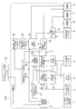
- FIG. 5 is a functional block diagram showing an internal configuration of the elevator control device according to the first to fourth embodiments of the present invention. It is explanatory drawing which shows an example of the basic setting data which the basic setting data memory
- FIG. 6 is a flowchart showing a flow of an operation when a car is stopped in the elevator control device according to the first to third embodiments of the present invention. It is a flowchart which shows the flow of the alerting
- FIG. 3 is a hardware configuration diagram showing a hardware configuration of an elevator control device according to Embodiments 1 to 4 of the present invention.
- FIG. 1 is an image diagram showing an operation of the elevator control apparatus according to the first embodiment of the present invention.
- FIG. 2 is a block diagram illustrating a configuration of the elevator control device according to the first embodiment.
- FIG. 3 shows an example of basic setting data in which a condition for switching from the “normal mode” to the “security operation mode” in the first embodiment is set.
- FIG. 4 shows an example of user information data for storing user information for each user.
- the elevator in which the elevator control device according to the first embodiment is installed includes a car 104, a hoistway (not shown) in which the car 104 moves up and down, and a machine room (not shown) provided in the upper part of the hoistway. And.
- An elevator control panel 110 (see FIG. 2) for controlling the operation of the car 104 is installed in the machine room.
- a car monitoring camera 105 is installed in the car 104.
- the car monitoring camera 105 images the car 104 and outputs video data in the car 104.
- hall monitoring cameras 103 are installed at the halls 100 and 107 on each floor. The hall monitoring camera 103 captures the halls 100 and 107 and outputs video data of the halls 100 and 107.
- the users 101 and 102 perform hall call registration by pressing a hall button installed at the hall.
- the user 101 is a male and the user 102 is a female.
- the car 104 is operated to land on the hall 100.
- the users 101 and 102 get on the car 104.
- the gender of the users 101 and 102 is determined based on the video data captured by the car monitoring camera 105. Thereby, gender information is stored for each of the users 101 and 102 in the user information data shown in FIG.
- an announcement instructing the users 101 and 102 in the car 104 to register the destination floor for each user is sent in the car 104.
- the announcement for example, “A crime prevention operation is in progress. All passengers should register the destination floor”.
- each user 101, 102 presses the button on the operation panel in the car to register the destination floor.
- which user has registered which destination floor is identified from the time when the destination floor is registered, the time of the video data, and the characteristics of the user.
- destination floor information is stored for each of the users 101 and 102 in the user information data shown in FIG.
- the destination floors of the users 101 and 102 are both “second floor”.
- the car 104 is operated to the destination floor registered by the users 101 and 102, and the car 104 is landed on the landing 107 on the destination floor.
- an announcement is made to flow in the car 104.
- the announcement for example, “It is a crime prevention operation. Please get off from the woman. Please wait for the man to close the door once.” According to the announcement, the female user 102 gets off first.
- the male user 101 does not follow the announcement instructions and the female user 102 gets off, it detects that the male user 101 gets off together. You may make it report to a management room. Further, after the male user 101 gets off, if the walking speed of the user 101 at the landing 107 is equal to or higher than the reference value, it is determined that the behavior of the user 101 is an abnormal behavior, a buzzer is issued, and the management room is notified. You may make it report.
- the elevator control apparatus performs a general normal elevator operation when the operation mode of the elevator is the normal mode.
- the basic setting data includes the following data.
- Code 31 “Security function”: Information indicating whether or not the elevator has a security function.
- Code 32 “Security function operating time zone”: Information indicating a time zone during which the security function is operated.
- Code 33 “Number of persons operating the crime prevention function”: Information indicating a threshold for the number of users for determining whether or not to activate the crime prevention function. When the number of users in the car 104 is equal to or less than the “operating number”, the security function is activated.
- Code 34 “Number of security function operating persons [female]”: Information indicating a threshold for the number of female users who operate the security function.
- Code 35 “Security function number of reports”: Information indicating a threshold value for the count value of the number of times of buzzer reports for determining whether or not to report to the management room. When the count value of the buzzer is larger than the “number of reports”, the management room is notified.
- Code 36 “crime prevention speed walking speed reference value”: information indicating a threshold for the walking speed of the user for determining whether or not the user's behavior is abnormal. When the user's walking speed is equal to or higher than the “reference value”, it is determined as abnormal and a buzzer is issued.
- Code 37 “Crime prevention function walking speed number of reports”: Information indicating a threshold value for the count value of the number of buzzer reports by determination based on walking speed. If the count value of the buzzer report is larger than the “Walking speed report count”, report to the management room. Note that the information of the codes 35 to 37 is not necessarily included in the basic setting data, and may be included as necessary.
- the user information data includes the following data.
- Code 38 “Gender”: Information on the gender of the user. If the user is female, “female” is stored, and if the user is male, “male” is stored.
- Code 39 “Boarding time”: Information on the time when the user gets on the car 104. In the example of FIG. 4, it is 9:10 am.
- Code 40 “Destination Floor”: Information on the destination floor registered by the user.
- Code 41 “Position”: Information on the position in the car 104 of the user. In FIG. 4, “position” information is not stored.
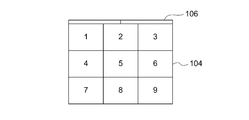
- the car 104 is divided into a plurality of sections, and a number is assigned to each section.
- the car monitoring camera 105 captures an image of the car 104 and analyzes the video data to identify the section where the user is present, and stores the section number as “position” information.
- the example of FIG. 8B is merely an example, and the car interior 104 may be divided into three sections, a front part, an intermediate part, and a rear part.
- the front region is the region of numbers 1 to 3 in FIG. 8B
- the middle region is the region of numbers 4 to 6 in FIG. 8B
- the rear region is the region of numbers 7 to 9 in FIG. 8B.
- the information of the code 41 is not necessarily included in the user data, and may be included as necessary.
- the elevator control apparatus includes a car call stop detection unit 1, an in-car destination floor registration unit 2, a boarding detection unit 3, an in-car image input unit 4, and a landing image input unit. 5, a door opening / closing unit 6, a reporting unit 7, a reporting unit 8, and a basic setting data input unit 22. These are provided outside the elevator control panel 110.
- the elevator control apparatus includes a stop floor registrant determination unit 9, a person behavior analysis unit 10, a gender determination unit 11, a walking speed analysis unit 12, a user destination floor.
- An association unit 13, a user sex association unit 14, and an operation mode switching unit 15 are provided.
- the elevator control apparatus includes a boarding position information update unit 16, a driving control unit 17, a getting-off operation detection unit 18, a getting-off operator determination unit 19, and a basic setting data storage unit. 20 and a user information data storage unit 21.
- FIG. 15 shows a hardware configuration that constitutes the elevator control apparatus according to the first embodiment.
- the elevator control device according to the first embodiment includes a processor 200, a memory 201, an input device 202, and an output device 203.
- the basic setting data storage unit 20 and the user information data storage unit 21 in FIG. The registrant determination unit 9, person behavior analysis unit 10, gender determination unit 11, walking speed analysis unit 12, user destination floor association unit 13, user gender association unit 14, driving mode switching unit 15, FIG.
- the boarding position information update unit 16, the driving control unit 17, the getting-off operation detection unit 18, and the getting-off operator determination unit 19 are realized when the processor 200 executes a program stored in the memory 201.
- a plurality of processors and a plurality of memories may cooperate to execute these functions.
- the door opening / closing unit 6, the reporting unit 7, and the reporting unit 8 are output devices 203. Further, these functions may be realized by a plurality of output devices.
- the car stop detection unit 1 detects whether or not the car 104 has stopped at the registration floor according to the car call registered by the users 101 and 102.
- the stop detection unit 1 by the car call outputs the detection result to the registrant determination unit 9 on the stop floor.
- the user in the car 104 registers the destination floor in the car destination floor registration unit 2.
- the car destination floor registration unit 2 includes a car operation panel provided in the car 104.
- the boarding detection unit 3 detects that the user at the landings 100 and 107 has boarded the car 104.
- the boarding detection unit 3 includes a hall monitoring camera 103 and a car monitoring camera 105.
- the boarding detection unit 3 may be configured by a weight sensor that is installed in the car 104 and measures the load weight of the car 104.
- the in-car image input unit 4 captures the image in the car 104 and inputs the in-car image data to the elevator control panel 110.
- the in-car image input unit 4 includes a car monitoring camera 105.
- the hall video input unit 5 captures the halls 100 and 107 and inputs the hall video data to the elevator control panel 110.
- the hall video input unit 5 includes a hall monitoring camera 103.
- the door opening / closing unit 6 performs opening / closing driving of the door 106 of the car 104.
- the door opening / closing part 6 is composed of a door driving device (not shown) provided in the car 104.
- the door driving device has a motor for opening and closing the door 106.
- the reporting unit 7 issues a buzzer.
- the reporting unit 7 includes a buzzer.
- the reporting unit 8 reports to the management room. For reporting, for example, sound a buzzer installed in the management room, turn on a lamp installed in the management room, send an announcement to the management room, or display a message on the computer screen installed in the management room , Etc.
- the registrant determination unit 9 at the stop floor refers to the user information data shown in FIG. It is determined whether or not there is a female user among the users who have registered. When there is a female user, the registrant determination unit 9 on the stop floor determines whether there is a male user among the users who have registered the registration floor. The registrant determination unit 9 on the stop floor outputs the determination result to the operation control unit 17.
- the person behavior analysis unit 10 detects the position of the user in the car 104 and the presence / absence of the movement of the user based on the car video data from the car video input unit 4.
- the sex determination unit 11 analyzes the in-car image data from the in-car image input unit 4 and determines the gender of the user in the car 104 when the boarding detection unit 3 detects the boarding of the user. .
- the determination result is output to the user sex association unit 14 and the operation mode switching unit 15.
- the gender determination unit 11 determines the gender of the user by pattern matching the in-car video data from the in-car video input unit 4 and characteristic data for each predetermined gender.
- the characteristic data for each gender includes, for example, data relating to height, data relating to shoulder width, data relating to the volume of the hair portion, data relating to the temperature of the cheek portion of the face, data relating to the color of the lip portion of the face, and data relating to the color of the clothing portion.
- Another example of the feature data for each gender is data related to the features of the walking posture for each gender. Comparing the walking posture of men and women, the displacement of the relative position of the shoulder part of the man is larger than that of the woman as a characteristic of the walking posture of the man, whereas the relative position of the waist part of the man The amount of displacement tends to be smaller than that of women. Therefore, from the in-car image data from the in-car image input unit 4, the displacement amount of the shoulder portion and the waist portion of each user is obtained, and the ratio of the displacement amount of the shoulder portion to the displacement amount of the waist portion is calculated.
- the gender of the user may be determined, such as male if the ratio value is equal to or greater than the threshold, and female if the ratio is less than the threshold.
- the walking speed analysis unit 12 calculates the walking speed of the user at the landing based on the landing video data from the landing video input means 5, and the walking speed is calculated based on the “crime prevention function walking speed standard” of the basic setting data in FIG. Compare with value. As a result of the comparison, when the walking speed is equal to or higher than the reference value, the walking speed analysis unit 12 determines that the movement of the user is abnormal. Note that the walking speed analysis unit 12 is used in the third embodiment to be described later, but is not necessarily required in the first embodiment, and thus is not necessarily provided.
- the user destination floor associating unit 13 associates, for each user, the user and the destination floor registered by the user based on the information from the car destination floor registration unit 2 and the person behavior analysis unit 10.
- the “destination floor” information of the user information data of FIG. 4 stored in the user information data storage unit 21 is updated.
- the user sex associating unit 14 is a diagram in which the user and the user's gender are associated with each other based on the determination result of the gender determining unit 11 and stored in the user information data storage unit 21.
- the sex (male / female) determined by the sex determination unit 11 is stored in the “sex” information of the user information data 4.
- the operation mode switching unit 15 switches the operation mode of the elevator based on at least one of the basic setting data in FIG. 3, the determination result of the gender determination unit 11, and the user information data in FIG. 4.
- the boarding position information update unit 16 determines that the current driving mode is the crime prevention driving mode based on the basic setting data of FIG. 3, the boarding position information updating unit 16 determines for each user based on the analysis result of the human behavior analysis unit 10. The “position” information of the user information data in FIG. 4 is updated.
- the operation control unit 17 operates the car 104 based on the basic setting data in FIG. 3, the signal from the registrant determination unit 9 at the stop floor, and the operation mode set by the operation mode switching unit 15, and The operation of the opening / closing unit 6, the reporting unit 7, and the reporting unit 8 is controlled.
- the getting-off operation detecting unit 18 detects whether or not the user has got off for each gender of the user based on the determination result from the getting-off operator determining unit 19.
- the getting-off operator determination unit 19 determines whether the user getting off at the registration floor is a woman or a man based on the user information data of FIG. The getting-off operator determination unit 19 determines the gender of the user who is getting off when the car 104 reaches the registered floor.
- the basic setting data storage unit 20 stores basic setting data shown in FIG.
- the basic setting data storage unit 20 includes a memory 201 (see FIG. 15) provided in the elevator control panel 110.
- the user information data storage unit 21 stores user information data shown in FIG.
- the user information data storage unit 21 includes a memory (see FIG. 15) provided in the elevator control panel 110.
- the basic setting data input unit 22 receives basic setting data from the outside.
- the input basic setting data is stored in the basic setting data storage unit 20.
- the basic setting data input unit 22 includes an interface device such as a keyboard and a mouse provided on the elevator control panel 110.
- the basic setting data input unit 22 is used in the fourth embodiment to be described later, but is not particularly necessary in the first embodiment, and thus is not necessarily provided. However, if the basic setting data input unit 22 is not provided, the basic setting data storage unit 20 stores the basic setting data of FIG.
- the number of users in the car 104 is equal to or less than the “number of users” in the basic setting data in FIG. 3 and the number of women in the car 104 is “ When it is equal to the “number of female movements”, the mode shifts to the “crime prevention driving mode”.
- the user destination floor association unit 13 causes the “destination floor” of the user information data in FIG.
- the destination floor is stored in the information.
- the person behavior analysis unit 10 analyzes the video data input from the in-car video input unit 4 and detects the presence or absence of movement of the user in the car 104.
- the boarding position information update unit 15 updates the “position” information of the user information data in FIG. 4 for the moved user based on the detection result of the person behavior analysis unit 10.
- the operation control unit 17 it is detected by the operation control unit 17 whether or not the car 104 is to be stopped.
- the registrant determination unit 9 on the stop floor has a female call registration on the stop floor from the “gender” information and the “destination floor” information of the user information data in FIG. It also detects whether there is a call registration.
- the stop detection unit 1 by the car call detects that the car 104 has stopped.
- the getting-off operation detection unit 18 determines the person getting off the vehicle. If the man starts the getting-off operation before the woman completes the getting-off operation, the reporting unit 7 issues a buzzer.
- the announcement part 7 issues an announcement such as “I was very sorry to wait ...” and again by the door opening / closing part 6 After the door is fully opened, the man starts getting off.
- FIG. 5 is a flowchart showing the operation during boarding in the first embodiment.
- step S1 the elevator control panel 110 sets the “security function” in the basic setting data in FIG. 3 to “with security function” and the current time is “security function operation time zone” in the basic setting data in FIG. It is determined whether it is within the range. If “no crime prevention function” or “no crime prevention function operation time zone”, the process proceeds to “no” in step S1 and ends the process of FIG. On the other hand, if “there is a crime prevention function” and “the crime prevention function operation time zone”, the process proceeds to “yes” in step S1.
- step S2 the boarding detection unit 3 determines whether or not the boarding of the user has been detected. When the boarding is not detected, the process proceeds to “no” in step S2, and the process of FIG. On the other hand, when the boarding is detected, the process proceeds to “yes” in step S2.
- step S3 the elevator control panel 110 receives the in-car image data from the in-car image input unit 4 by the sex determination unit 11.
- the sex determination unit 11 analyzes the video data in the car and determines the sex of the user.
- the feature data of each user is stored as feature data for specifying each user.
- the feature data is preferably the color or shape of the clothes. Alternatively, the features used in the gender determination may be used as they are.
- step S4 the elevator control panel 110 causes the user gender associating unit 14 to add gender information to the “gender” information of the user information data in FIG. 4 for each user based on the determination result of the gender determining unit 11. Set.
- step S5 the elevator control panel 110 sets the boarding time information in the “boarding time” information of the user information data in FIG. 4 for each user.
- step S6 the elevator control panel 110 refers to the user information data in FIG. 4 to determine the total number of users and updates the number of passengers in the memory 201.
- step S7 the elevator control panel 110 determines whether or not the current operation mode is the “crime prevention operation mode”. If it is in the “security operation mode”, the process proceeds to “yes” in step S7, and the process of FIG. On the other hand, if it is not in the “security operation mode”, the process proceeds to “no” in step S7.
- step S8 the elevator control panel 110 determines whether or not the current number of passengers is equal to or less than the “number of people with crime prevention function” in the basic setting data of FIG. If it is not equal to or less than the “number of people with security function”, the process proceeds to “no” in step S8, and the process of FIG. On the other hand, if the number is equal to or less than the “number of people with security function”, the process proceeds to “yes” in step S8.
- step S9 the elevator control panel 110 determines whether or not the number of women in the car 104 is equal to the “number of crime prevention function persons [women]” in the basic setting data of FIG. If it is different from “the crime prevention function number of persons [female]”, the process proceeds to “no” in step S9, and the process of FIG. On the other hand, if it is equal to “the number of security functions operating [female]”, the process proceeds to “yes” in step S9.
- step S10 the elevator control panel 110 causes the operation mode switching unit 15 to set the operation mode to “security operation mode”.
- step S11 an announcement that a crime prevention operation is in progress is issued, and the processing in FIG. 5 is terminated.
- the announcement “You are driving in crime prevention. On the floor where a woman gets off, after the woman gets off, she closes the door and then gets off to the man. Thank you for your cooperation.”
- FIG. 6 is a flowchart showing the operation at the time of car call registration according to the first embodiment of the present invention. The flow of FIG. 6 is executed after the flow of FIG.
- step S12 the elevator control panel 110 determines whether or not a car call has been registered based on information of call registration by the user in the car destination floor registration unit 2. That is, it is determined whether or not the user has pressed any floor button on the car operation panel in the car 104 to designate the destination floor. If the car call is not registered, the process proceeds to “no” in step S12, and the process of FIG. On the other hand, if the car call is registered, the process proceeds to “yes” in step S12.
- step S13 the elevator control panel 110 sets the “security function” in the basic setting data in FIG. 3 to “with security function” and the current time is “security function operation time zone” in the basic setting data in FIG. It is determined whether it is within the range. If “no crime prevention function” or “no crime prevention function operating time zone”, the process proceeds to “no” in step S13, and the process of FIG. On the other hand, if “there is a crime prevention function” and “the crime prevention function operating time zone”, the process proceeds to “yes” in step S13.
- step S14 the elevator control panel 110 analyzes the in-car image data from the in-car image input unit 4 by the person behavior analysis unit 10, and identifies the user who has registered the car call. That is, based on the video data at the time when the user registered the destination floor on the car operation panel in the car 104, the user who made the car call registration is specified from the characteristics of the user who made the car call registration. That is, the user is identified by comparing the feature data stored in step S3 of FIG. 5 with the user who registered the car call.
- step S15 the elevator control panel 110 associates the user with the destination floor for each user who has registered the destination floor by the user destination floor associating unit 13, and displays the “destination floor” of the user information data in FIG.
- the destination floor is set in the information, and the processing in FIG.
- FIG. 7 is a flowchart showing an operation for determining whether or not a car call is registered according to the first embodiment. The flow of FIG. 7 is executed after the flow of FIG.
- step S16 the elevator control panel 110 sets the “security function” in the basic setting data of FIG. 3 to “with security function” and the current time is “security function operation time zone” in the basic setting data of FIG. It is determined whether it is within the range. If “no crime prevention function” or “no crime prevention function operating time zone”, the process proceeds to “no” in step S16, and the process of FIG. 7 ends. On the other hand, if “there is a crime prevention function” and “the crime prevention function operating time zone”, the process proceeds to “yes” in step S16.
- step S17 the elevator control panel 110 refers to the user information data of FIG. 4 stored in the user information data storage unit 21, and the “destination floor” information of the user information data is not set. In addition, it is determined whether or not there is a user whose time from the boarding time to the current time in the “boarding time” information of the user information data is equal to or longer than a predetermined time. If the user does not exist, the process proceeds to “no” in step S17, the departure prevention is canceled in step S20, and the process of FIG. On the other hand, if the user exists, the process proceeds to “yes” in step S17.
- step S18 the elevator control panel 110 drives the notification unit 7 to issue an announcement that all users need to register the destination floor.
- step S19 the elevator control panel 110 prevents departure, and FIG. Terminate the process.
- the announcement “A crime prevention operation is in progress. All passengers, please register the destination floor”.
- step S17 the process of FIG. 7 is repeatedly executed to cause all users to register the car call.
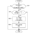
- FIG. 8A is a flowchart showing the update operation of the user location information according to the first embodiment.
- step S21 the elevator control panel 110 sets the “security function” in the basic setting data in FIG. 3 to “with security function” and the current time is “security function operation time zone” in the basic setting data in FIG. It is determined whether it is within the range. If “no crime prevention function” or “no crime prevention function operating time zone”, the process proceeds to “no” in step S21, and the process of FIG. 8A is terminated. On the other hand, if “there is a crime prevention function” and “the crime prevention function operation time zone”, the process proceeds to “yes” in step S21.
- step S22 the elevator control panel 110 determines whether or not the current operation mode is the “crime prevention operation mode”. If it is not in the “security mode”, the process proceeds to “no” in step S22, and the process of FIG. 8A is terminated. On the other hand, if it is in the “security operation mode”, the process proceeds to “yes” in step S22.
- step S23 the elevator control panel 110 analyzes the in-car image input from the in-car image input unit 4 by the human behavior analysis unit 10, and acquires the position information of the user.
- the “position” information for example, as shown in FIG. 8B, the car 104 is divided into a plurality of sections in advance, and a number is assigned to each section.
- the car monitoring camera 105 captures an image of the car 104 and analyzes the video data to identify the section where the user is present, and obtains the section number as “position” information.
- FIG. 8B is a plan view showing a floor surface in the car 104, and reference numeral 106 is a door of the car 104. Further, the example of FIG.
- the car interior 104 may be divided into three sections, a front part, an intermediate part, and a rear part.
- the front region is the region of numbers 1 to 3 in FIG. 8B
- the middle region is the region of numbers 4 to 6 in FIG. 8B
- the rear region is the region of numbers 7 to 9 in FIG. 8B.
- step S24 the elevator control panel 110 causes the boarding position information update unit 16 to change the position of the user acquired in step S23 into the "position" information shown in the user information data of FIG. 4 for each user. Information is set, and the process of FIG. 8 ends.
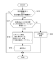
- FIG. 9 is a flowchart showing the operation at the time of determining the car stop according to the first embodiment. The flow of FIG. 9 is executed after the flow of FIG. 7 or FIG. 8A.
- step S25 the elevator control panel 110 determines whether or not the operation control unit 17 determines that the car 104 is to be stopped on any floor.
- the stop in this case includes two types of stop by car call registration and stop by landing call registration. If the car has not been determined to stop, the process proceeds to “no” in step S25, and the process of FIG. 9 ends. On the other hand, if the car is determined to stop, the process proceeds to “yes” in step S25.
- step S26 the elevator control panel 110 sets the “security function” in the basic setting data of FIG. 3 to “with security function” and the current time is “security function operation time zone” in the basic setting data of FIG. It is determined whether it is within the range. If “no crime prevention function” or “no crime prevention function operation time zone”, the process proceeds to “no” in step S26, and the process of FIG. 9 ends. On the other hand, if “there is a crime prevention function” and “the crime prevention function operating time zone”, the process proceeds to “yes” in step S26.
- step S27 the elevator control panel 110 determines whether or not the current operation mode is the “crime prevention operation mode”. If it is not in the “security operation mode”, the process proceeds to “no” in step S27, and the process of FIG. On the other hand, if it is in the “security operation mode”, the process proceeds to “yes” in step S27.
- step S ⁇ b> 28 the elevator control panel 110 determines whether or not the stop of the car 104 confirmed in step S ⁇ b> 25 is a stop due to a car call by the car call stop detection unit 1. If the stop is not due to a car call, the process proceeds to “no” in step S28, and the process of FIG. On the other hand, if the stop is due to a car call, the process proceeds to “yes” in step S28.
- step S29 the elevator control panel 110 refers to the user information data of FIG. 4 and the “destination floor” information of the user information data is the next stop floor and the “sex” of the user information data. It is determined whether or not there is a user whose information is “female”. If there is no woman whose next stop floor is the destination floor, the process proceeds to “no” in step S29, and the process of FIG. 9 ends. On the other hand, if there is a woman whose stop floor is the destination floor, the process proceeds to “yes” in step S29.
- step S30 the elevator control panel 110 refers to the user information data of FIG. 4 and the “destination floor” information of the user information data is the next stop floor and the “sex” of the user information data. It is determined whether or not there is a user whose information is “male”. If there is no male whose destination floor is the destination floor, the process proceeds to “no” in step S30, and the process of FIG. On the other hand, if there is a man whose stop floor is the destination floor, the process proceeds to “yes” in step S30.
- step S31 the elevator control panel 110 controls the reporting unit 7 so that the woman gets off first, and once the woman gets off, the door is closed, and then the door opens and then the man gets off. Alert.
- the announcement “You are driving in crime prevention. Please get off from the woman. The man will close the door once, so please be patient”.
- step S32 the elevator control panel 110 switches the operation mode to the “get-off determination mode” by the operation mode switching unit 15, and ends the process of FIG.
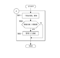
- FIG. 10 is a flowchart showing the operation when the car is stopped according to the first embodiment. The flow of FIG. 10 is executed after the flow of FIG.
- step S33 the car stop detection unit 1 determines whether the car has stopped. If the car is not stopped, the process proceeds to “no” in step S33, and the process of FIG. On the other hand, if the car stops, the process proceeds to “yes” in step S33.
- step S34 the elevator control panel 110 sets the “security function” in the basic setting data in FIG. 3 to “with security function” and the current time is “security function operation time zone” in the basic setting data in FIG. It is determined whether it is within the range. If “no crime prevention function” or “no crime prevention function operating time zone”, the process proceeds to “no” in step S34, and the process of FIG. On the other hand, if “there is a crime prevention function” and “the crime prevention function operation time zone”, the process proceeds to “yes” in step S34.
- step S35 the elevator control panel 110 determines whether or not the current operation mode is the “crime prevention operation mode”. If it is not in the “security operation mode”, the process proceeds to “no” in step S35, and the process of FIG. On the other hand, if it is in the “security operation mode”, the process proceeds to “yes” in step S35.
- step S36 the elevator control panel 110 analyzes the in-car image data input from the in-car image input unit 4 by the human behavior analysis unit 10, and analyzes the movement trajectory of the user.
- step S37 the elevator control panel 110 determines whether or not the user is moving in the door direction based on the movement trajectory of the user acquired in step S36 by the getting-off operator determination unit 19. If the user is moving in the door direction, since the movement is a “get-off operation”, the process proceeds to “yes” in step S37. In step S38, the “get-off operation detection state” is set, and the process proceeds to step S40. On the other hand, if the user is not moving in the door direction, the process proceeds to “no” in step S37, and in step S39, the “get-off operation is released” state, and the process proceeds to step S40.
- step S40 the elevator control panel 110 determines whether or not it is in the “alighting operation detection state”. If it is not the “alighting operation detection state”, the process proceeds to “no” in step S40, and the process of FIG. On the other hand, in the case of “alighting operation detection state”, the process proceeds to “yes” in step S40.
- step S41 the elevator control panel 110 determines whether or not the “destination floor” information in the user information data of FIG. 4 of the user performing the “getting-off operation” is equal to the stop floor. If the stop floor is not equal to the destination floor of the user performing the “getting off” operation, the process proceeds to “no” in step S41, a buzzer is issued in step S59, and it is necessary to get on to the destination floor in step S60. An announcement to the effect is issued and the processing in FIG. 10 is terminated. On the other hand, if the stop floor is equal to the destination floor of the user performing the “getting-off operation”, the process proceeds to “yes” in step S41.
- step S42 the elevator control panel 110 determines whether or not the current operation mode is the “get-off determination mode”. If it is not in the “get-off determination mode”, the process proceeds to “no” in step S42, and in step S55, it is determined whether or not all of the passengers whose stop floor is the destination floor are completed. If all of the passengers have not got off, the process proceeds to “no” in step S55, and the process in FIG. On the other hand, when all of the passengers have exited, the process proceeds to “yes” in step S55, and in step S56, it is determined whether or not there are zero men in the car. If the number of males in the car is zero, the process proceeds to “yes” in step S56.
- step S58 the operation mode switching unit 15 sets the operation mode to “normal mode”, and the process of FIG.
- the process proceeds to “no” in step S56, and in step S57, it is determined whether or not there are zero females in the car. If there are no women in the car, the process proceeds to “yes” in step S57.
- step S58 the operation mode switching unit 15 sets the operation mode to “normal mode”, and the process of FIG. When the number of women in the car is not zero, the process proceeds to “no” in step S57, and the process of FIG.
- step S42 if it is in the “get-off determination mode” in step S42, the process proceeds to “yes” in step S42.
- step S43 the elevator control panel 110 determines whether or not the “sex” information in the user information data of FIG. 4 of the user performing the “getting-off operation” is “female”. In step S43, if the passenger performing the “getting-off operation” is “female”, the process proceeds to “yes” in step S43, and the getting-off operation of “female” is completed by the getting-off operation detecting unit 18 in step S44. It is determined whether or not. When the “female” getting-off operation is not completed, the process proceeds to “no” in step S44, and the process of FIG.
- step S44 the door is closed
- step S45 the door is closed
- step S46 it is determined whether or not the door is fully closed. If the door is not fully closed, the process proceeds to “no” in step S46, and the process of FIG. On the other hand, if the door is fully closed, the process proceeds to “yes” in step S46.
- step S47 after a predetermined time has elapsed from when the door is fully closed, an announcement such as “I was very sorry to wait.” After issuing the notification, the door is opened in step S48, and the process of FIG.
- the fixed time at this time is arbitrarily set within a range of about 10 seconds to 1 minute.
- step S43 the process proceeds to “no” in step S43, and it is determined in step S49 whether or not “female” has finished getting off. To do.
- step S49 if “female” has not finished getting off, the process proceeds to “no” in step S49, a buzzer is issued in step S53, and in step S54, the male closes the door after the female gets off After the door is opened again, an announcement is issued indicating that it is necessary to get off the vehicle, and the processing in FIG. 10 is terminated.
- the process of FIG. 10A is a process performed in the second embodiment described later, and is not performed in the first embodiment.
- step S49 the process proceeds to “yes” in step S49.
- the process of FIG. 10B is a process performed in a third embodiment to be described later, and is not performed in the first embodiment.
- step S50 the elevator control panel 110 determines whether all the users whose “destination floor” information in the user information data in FIG. 4 is equal to the stop floor have completed the getting-off operation. If all the users whose stop floor is the destination floor have not completed the getting-off operation, the process proceeds to “no” in step S50, and the process of FIG. On the other hand, if all the passengers whose stop floor is the destination floor have completed the getting-off operation, the process proceeds to “yes” in step S50.
- step S51 the elevator control panel 110 cancels the “get-off determination mode” by the operation mode switching unit 15, and in step S52, sets the operation mode to “normal mode” and ends the processing of FIG.
- the elevator control device is determined by the gender determination unit 11 that determines the gender of the user and the gender determination unit 11 based on the video data of the user in the elevator car 104. Based on the gender of the user, it is determined whether or not the composition of the user is a combination of one woman and one or more men.
- An in-car destination where a destination floor for each user is registered when the operation mode switching unit 15 for switching the operation mode from the normal mode to the crime prevention operation mode and the elevator 104 is provided in the crime prevention operation mode.
- the floor registration unit 2 the user destination floor association unit 13 that associates the user with the destination floor for each user who has registered the destination floor in the car destination floor registration unit 2, the car call registration and Based on the play call registration, and a driving control unit 17 for controlling the door opening and closing operation of the navigation and car 104 of the car 104.
- the operation control unit 17 is a user who is associated with the destination floor by the user destination floor association unit 13, and
- the destination floor is a destination floor that is also associated with other users, after the female user gets off, the car 104 is once closed and then opened again for other users. To do.
- the driving control unit 17 determines whether the other user Run the car to the next destination floor associated with the user.
- the user's gender is automatically analyzed at the time of boarding, and when a user includes one woman + male, it shifts to a crime prevention driving mode. All users register for the destination floor one by one.
- the destination floor is registered, for each user, the user is associated with the destination floor and the user is tracked.
- the car 104 arrives on the female destination floor, the female gets off first, and once the female gets off, the door is fully closed. After the door is fully closed, after a certain period of time, the door is fully opened again and the man gets off. Thereby, a distance can be provided between the woman and the man, and the woman can be prevented from being tracked by the man.
- FIG. 1 is an image diagram showing an operation of the elevator control apparatus according to the second embodiment of the present invention. Since the basic operation of the second embodiment is the same as that of the first embodiment described with reference to FIG. 1, the description of FIG. 1 is omitted here.
- the operation of the elevator control device of the second embodiment is basically the same as that of the first embodiment described above.
- the difference from the first embodiment is only that the process of FIG. 10A is performed in the second embodiment. Below, only this difference is demonstrated and description is abbreviate
- the operation control unit 17 shown in FIG. 2 determines the person getting off the vehicle using the getting-off operation detecting unit 18, and before the woman completes the getting-off operation, Is started by the reporting unit 7 as many times as the number of “reporting” set in the basic setting data in FIG. 3, and if the getting-off operation is not stopped, the reporting unit 8 manages it. Report to the room.
- FIG. 11 is a flowchart showing an operation of the process (A), that is, a notification operation to the management room.
- step S49 of FIG. 10 when it is determined in step S49 of FIG. 10 that the male has started the getting-off operation before the woman has completed the getting-off operation when the car is stopped, the process proceeds to “no” in step S49.
- step S53 the notification unit 7 issues a buzzer, and in step S54, an announcement is issued.
- the processing so far is the same as in the first embodiment.
- the process proceeds to the flow of FIG. 11 showing the process (A).
- step S61 the elevator control panel 11 updates the count value of “number of times of notification” of buzzer notification, and in step S62, the updated “number of times of notification” is changed to FIG. It is determined whether or not it is larger than the “number of reports” in the basic setting data. If the “number of notifications” is equal to or less than the “number of notifications”, the process proceeds to “no” in step S62, and the process of FIG. On the other hand, if the “number of reports” is larger than the “number of reports”, the process proceeds to “yes” in step S62. In step S63, the reporting unit 8 reports to the management room, and the process of FIG.
- the second embodiment since the second embodiment has basically the same configuration and operation as the first embodiment, the same effects as those of the first embodiment can be obtained. Furthermore, in the second embodiment, when a man starts getting off before the woman completes the getting-off operation when the user gets off, the notification unit 7 repeatedly issues a notification, and still the getting-off operation is performed. When not stopping, it was set as the structure which reports to a management room by the report part 8. FIG. Therefore, repeated buzzer alerts can prompt male users who do not follow the rules during crime prevention driving to follow the rules. In addition, for male users who do not stop getting off despite repeated buzzer reports, the management room manager can urgently go to the site, which is a security effect. Is further improved.
- FIG. 1 is an image diagram showing the operation of the elevator control apparatus according to Embodiment 3 of the present invention. Since the basic operation of the third embodiment is the same as that of the first and second embodiments described with reference to FIG. 1, the description of FIG. 1 is omitted here.
- the operation of the elevator control device of the third embodiment is basically the same as that of the first and second embodiments described above.
- the difference from the first and second embodiments is only that the process of FIG. 10B is performed in the third embodiment. Below, only this difference is demonstrated and description is abbreviate
- the operation control unit 17 shown in FIG. 2 inputs the landing video data from the landing video input unit 5 by the walking speed analysis unit 12, and after getting off from the car 104, Measure the walking speed of the user who passes.
- the walking speed is equal to or higher than the “walking speed reference value” set in the basic setting data of FIG. 3, the reporting unit 7 issues a buzzer and an announcement. In this way, if the buzzer is repeatedly issued as many times as the number of “walking speed alerts” set in the basic setting data in FIG. 3, the walking speed does not fall below the reference value set in the basic setting data. Report to the management room by part 8.
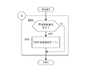
- FIG. 12 is a flowchart showing the operation of the process (B), that is, the operation for shifting to the walking speed confirmation mode.
- step S64 the elevator control panel 110 determines whether or not “male” has completed the getting-off operation. If “male” has not completed the getting-off operation, the process proceeds to “no” in step S64, and the process of FIG. On the other hand, when the “male” completes the getting-off operation, the process proceeds to “yes” in step S64, and in step S65, the operation mode switching unit 15 shifts to the “walking speed confirmation mode” and ends the process of FIG. To do.
- FIG. 13 is a flowchart showing the walking speed monitoring operation in the “walking speed confirmation mode” according to the third embodiment.
- step S66 the elevator control panel 110 sets the “security function” in the basic setting data in FIG. 3 to “with crime prevention function” and the current time is “security function operation time zone” in the basic setting data in FIG. It is determined whether it is within the range. If “no crime prevention function” or “no crime prevention function operating time zone”, the process proceeds to “no” in step S66, and the process of FIG. On the other hand, if “there is a crime prevention function” and “the crime prevention function is operating”, the process proceeds to “yes” in step S66.
- step S67 it is determined whether or not the “walking speed confirmation mode” is set. If it is not “walking speed confirmation mode”, the process proceeds to “no” in step S67, and the process of FIG. On the other hand, if it is “walking speed confirmation mode”, the process proceeds to “yes” in step S67.
- step S68 the elevator control panel 11 uses the walking speed analysis unit 12 to analyze the landing video data from the landing video input unit 5, and analyzes the movement trajectory and the movement time of the user moving on the landing.
- step S69 the elevator control panel 11 determines whether or not the user moving on the landing is moving in a direction away from the elevator, based on the movement trajectory and the movement time of the user obtained in step S68. . If the user moving on the landing is moving in a direction approaching the elevator, the process proceeds to “no” in step S69, and the “passing operation on the landing” is canceled in step S71, and the process proceeds to step S72. On the other hand, if the user moving on the landing is moving in a direction away from the elevator, the process proceeds to “yes” in step S69. In step S70, “landing operation” is set as a detection state, and the process proceeds to step S72.
- step S ⁇ b> 72 the elevator control panel 110 determines whether or not “landing operation” is being detected. If it is determined in step S72 that the “passing hall operation” is not being detected, the process proceeds to “no” in step S72. In step S73, it is determined whether or not the operation mode is “normal mode”. When the operation mode is not “normal mode”, the process proceeds to “no” in step S73, and the process of FIG. On the other hand, when the driving mode is “normal mode”, the process proceeds to “yes” in step S73, and in step S74, the “walking speed confirmation mode” is canceled by the driving mode switching unit 15 and the process of FIG. To do.
- step S72 the process proceeds to “yes” in step S72, and the walking speed is measured in step S75.
- step S76 the walking speed is the basic setting data shown in FIG. It is determined whether or not it is equal to or higher than the “walking speed reference value”. If the walking speed is not equal to or higher than the “walking speed reference value”, the process proceeds to “no” in step S76, and the process of FIG. On the other hand, if the walking speed is equal to or higher than the “walking speed reference value”, the process proceeds to “yes” in step S76, and the count value of “the number of times of reporting by walking speed” is updated in step S77.
- step S78 it is determined whether or not the “number of times of reporting by walking speed” is larger than the “number of times of reporting of walking speed” in the basic setting data of FIG.
- the process proceeds to “no” in step S78, and the process of FIG.
- the process proceeds to “yes” in step S78, and the management room is notified in step S79, and the process of FIG.
- the third embodiment has basically the same configuration and operation as those of the first and second embodiments, the same effects as those of the first and second embodiments can be obtained. Further, in the third embodiment, the walking speed of the user passing through the hall is measured, and when the walking speed is equal to or higher than the reference value, the buzzer report and the announcement report are performed by the reporting unit 7. When the value does not fall below the reference value, the reporting unit 8 reports to the management room, so that it is possible to prevent female users from being tracked by male users after getting off.
- FIG. 1 is an image diagram showing the operation of the elevator control apparatus according to Embodiment 4 of the present invention. Since the basic operation of the fourth embodiment is the same as that of the first to third embodiments described with reference to FIG. 1, the description of FIG. 1 is omitted here.
- the operation of the elevator control device of the fourth embodiment is basically the same as that of the first to third embodiments described above.
- the only difference from the first to third embodiments is that, in the fourth embodiment, the basic setting data in FIG. 3 can be changed by the elevator administrator in accordance with the change in the user's usage state. It is. Below, only this difference is demonstrated and description is abbreviate
- the manager of the elevator may be a manager of the management room or a person in charge of the elevator maintenance company.
- an administrator inputs setting data through the basic setting data input unit 22 shown in FIG. 2, and the basic setting shown in FIG. 3 stored in the basic setting data storage unit 20 is stored. Change the data in the data to the input setting data.
- FIG. 14 is a flowchart showing the basic setting data changing operation according to the fourth embodiment of the present invention.
- step S80 the administrator operates a personal computer or the like connected to the elevator control panel 110 to input a password and open a port.
- step S81 the administrator waits until there is a reception event.
- step S81 If there is a reception event, the process proceeds to “There is a reception event” in step S81.
- step S82 the basic setting data shown in FIG. 3 is rewritten with the received data, and the process returns to step S81 to wait for the next reception event. Note that the process in FIG. 14 ends when the administrator closes the port.
- the fourth embodiment since the fourth embodiment has basically the same configuration and operation as those of the first to third embodiments, the same effects as those of the first to third embodiments can be obtained. Furthermore, in the fourth embodiment, the basic setting data in FIG. 3 can be changed by the administrator in accordance with the change in the usage state of the user. Therefore, the crime prevention of the elevator can be performed using the optimal basic setting data. Since driving can be performed, convenience is improved.
- the condition for switching the operation mode from the normal mode to the crime prevention operation mode is not limited to the identification of “one woman and one man” by gender determination in the in-car image analysis, For example, “two women and men” or “the number of men is more than women” may be used.
- the identification may be performed using an RFID tag instead of the in-car image analysis.
- each user carries an RFID tag in which user information is registered in advance.
- user information for example, in addition to each user's ID information, each user's “floor of apartment room” information, “age” information, and, if the user is a child, the parent of the user ID information, and, if the user is a woman, ID information of the user's family.
- the information in the RFID tag is read by the RFID reader installed in the hall or the car.
- the conditions for switching the driving mode from the normal mode to the crime prevention driving mode are as follows. It can also be “Who is a woman and a man other than her family”, “Is it a resident on a higher floor, or something else”.
Landscapes
- Engineering & Computer Science (AREA)
- Automation & Control Theory (AREA)
- Indicating And Signalling Devices For Elevators (AREA)
- Maintenance And Inspection Apparatuses For Elevators (AREA)
- Elevator Control (AREA)
- Elevator Door Apparatuses (AREA)
Abstract
Selon l'invention, quand des utilisateurs rentrent dans un ascenseur, ce dispositif de commande d'ascenseur analyse automatiquement le sexe des utilisateurs, et passe dans un mode de sécurité s'il y a une femme et un homme. Chacun des utilisateurs enregistre un étage de destination sur une base individuelle. Quand les étages de destination sont enregistrés, les étages de destination sont associés aux utilisateurs individuels. Quand une cabine atteint l'étage de destination de la femme, elle descend en premier, puis la porte est complètement fermée une fois. Après qu'un temps spécifié s'est écoulé depuis que la porte a été complètement fermée, la porte est complètement ouverte à nouveau, et l'homme descend. Par conséquent, il est possible de maintenir la distance entre la femme et l'homme et d'empêcher la femme d'être suivie par l'homme.
Priority Applications (3)
| Application Number | Priority Date | Filing Date | Title |
|---|---|---|---|
| PCT/JP2015/085498 WO2017104071A1 (fr) | 2015-12-18 | 2015-12-18 | Dispositif de commande d'ascenseur |
| JP2017556295A JP6430035B2 (ja) | 2015-12-18 | 2015-12-18 | エレベーター制御装置 |
| CN201580085261.0A CN108367886B (zh) | 2015-12-18 | 2015-12-18 | 电梯控制装置 |
Applications Claiming Priority (1)
| Application Number | Priority Date | Filing Date | Title |
|---|---|---|---|
| PCT/JP2015/085498 WO2017104071A1 (fr) | 2015-12-18 | 2015-12-18 | Dispositif de commande d'ascenseur |
Publications (1)
| Publication Number | Publication Date |
|---|---|
| WO2017104071A1 true WO2017104071A1 (fr) | 2017-06-22 |
Family
ID=59056205
Family Applications (1)
| Application Number | Title | Priority Date | Filing Date |
|---|---|---|---|
| PCT/JP2015/085498 Ceased WO2017104071A1 (fr) | 2015-12-18 | 2015-12-18 | Dispositif de commande d'ascenseur |
Country Status (3)
| Country | Link |
|---|---|
| JP (1) | JP6430035B2 (fr) |
| CN (1) | CN108367886B (fr) |
| WO (1) | WO2017104071A1 (fr) |
Cited By (6)
| Publication number | Priority date | Publication date | Assignee | Title |
|---|---|---|---|---|
| US20190128046A1 (en) * | 2017-10-26 | 2019-05-02 | Fuji Xerox Co., Ltd. | Apparatus, management system, and non-transitory computer readable medium |
| JP2020011841A (ja) * | 2018-07-20 | 2020-01-23 | 東芝エレベータ株式会社 | エレベータの運転制御方法 |
| JP2020019600A (ja) * | 2018-07-31 | 2020-02-06 | 株式会社日立製作所 | マルチカーエレベーター |
| US20220406069A1 (en) * | 2019-12-02 | 2022-12-22 | Nec Corporation | Processing apparatus, processing method, and non-transitory storage medium |
| KR102672144B1 (ko) * | 2023-02-16 | 2024-06-03 | 신양건 | 엘리베이터용 응급상황 감시시스템 |
| JP7516582B1 (ja) | 2023-01-12 | 2024-07-16 | 東芝エレベータ株式会社 | エレベータシステム |
Families Citing this family (1)
| Publication number | Priority date | Publication date | Assignee | Title |
|---|---|---|---|---|
| WO2022029860A1 (fr) * | 2020-08-04 | 2022-02-10 | 三菱電機株式会社 | Système de suivi de corps mobile, dispositif de suivi de corps mobile, programme et procédé de suivi de corps mobile |
Citations (5)
| Publication number | Priority date | Publication date | Assignee | Title |
|---|---|---|---|---|
| JPS601775U (ja) * | 1983-06-17 | 1985-01-08 | 三菱電機株式会社 | エレベ−タのかご内異常検出器 |
| JPS61119580A (ja) * | 1984-11-13 | 1986-06-06 | 株式会社日立製作所 | エレベ−タ−の防犯装置 |
| JP2007261722A (ja) * | 2006-03-28 | 2007-10-11 | Megachips System Solutions Inc | エレベータかご内の表示装置およびエレベータかご内の表示方法 |
| JP2008120549A (ja) * | 2006-11-14 | 2008-05-29 | Mitsubishi Electric Corp | エレベータの呼び登録装置 |
| JP2008239297A (ja) * | 2007-03-27 | 2008-10-09 | Mitsubishi Electric Corp | エレベータ装置 |
Family Cites Families (3)
| Publication number | Priority date | Publication date | Assignee | Title |
|---|---|---|---|---|
| JP5596423B2 (ja) * | 2010-06-04 | 2014-09-24 | 株式会社日立国際電気 | エレベータ制御システム |
| JP2012017167A (ja) * | 2010-07-07 | 2012-01-26 | Nec Embedded Products Ltd | エレベータの防犯システム及びエレベータの制御方法 |
| KR20150069033A (ko) * | 2011-05-10 | 2015-06-22 | 미쓰비시덴키 가부시키가이샤 | 엘리베이터의 알림 시스템 |
-
2015
- 2015-12-18 JP JP2017556295A patent/JP6430035B2/ja active Active
- 2015-12-18 CN CN201580085261.0A patent/CN108367886B/zh active Active
- 2015-12-18 WO PCT/JP2015/085498 patent/WO2017104071A1/fr not_active Ceased
Patent Citations (5)
| Publication number | Priority date | Publication date | Assignee | Title |
|---|---|---|---|---|
| JPS601775U (ja) * | 1983-06-17 | 1985-01-08 | 三菱電機株式会社 | エレベ−タのかご内異常検出器 |
| JPS61119580A (ja) * | 1984-11-13 | 1986-06-06 | 株式会社日立製作所 | エレベ−タ−の防犯装置 |
| JP2007261722A (ja) * | 2006-03-28 | 2007-10-11 | Megachips System Solutions Inc | エレベータかご内の表示装置およびエレベータかご内の表示方法 |
| JP2008120549A (ja) * | 2006-11-14 | 2008-05-29 | Mitsubishi Electric Corp | エレベータの呼び登録装置 |
| JP2008239297A (ja) * | 2007-03-27 | 2008-10-09 | Mitsubishi Electric Corp | エレベータ装置 |
Cited By (12)
| Publication number | Priority date | Publication date | Assignee | Title |
|---|---|---|---|---|
| US20190128046A1 (en) * | 2017-10-26 | 2019-05-02 | Fuji Xerox Co., Ltd. | Apparatus, management system, and non-transitory computer readable medium |
| JP2019079408A (ja) * | 2017-10-26 | 2019-05-23 | 富士ゼロックス株式会社 | 装置、管理システム及びプログラム |
| US11015379B2 (en) * | 2017-10-26 | 2021-05-25 | Fuji Xerox Co., Ltd. | Apparatus, management system, and non-transitory computer readable medium for entrance control |
| JP7155508B2 (ja) | 2017-10-26 | 2022-10-19 | 富士フイルムビジネスイノベーション株式会社 | 装置、管理システム及びプログラム |
| JP2020011841A (ja) * | 2018-07-20 | 2020-01-23 | 東芝エレベータ株式会社 | エレベータの運転制御方法 |
| JP2020019600A (ja) * | 2018-07-31 | 2020-02-06 | 株式会社日立製作所 | マルチカーエレベーター |
| WO2020026539A1 (fr) * | 2018-07-31 | 2020-02-06 | 株式会社日立製作所 | Ascenseur à cabines multiples |
| JP7141273B2 (ja) | 2018-07-31 | 2022-09-22 | 株式会社日立製作所 | マルチカーエレベーター |
| US20220406069A1 (en) * | 2019-12-02 | 2022-12-22 | Nec Corporation | Processing apparatus, processing method, and non-transitory storage medium |
| US12530900B2 (en) * | 2019-12-02 | 2026-01-20 | Nec Corporation | Processing apparatus, processing method, and non-transitory storage medium |
| JP7516582B1 (ja) | 2023-01-12 | 2024-07-16 | 東芝エレベータ株式会社 | エレベータシステム |
| KR102672144B1 (ko) * | 2023-02-16 | 2024-06-03 | 신양건 | 엘리베이터용 응급상황 감시시스템 |
Also Published As
| Publication number | Publication date |
|---|---|
| JP6430035B2 (ja) | 2018-11-28 |
| JPWO2017104071A1 (ja) | 2018-03-29 |
| CN108367886B (zh) | 2020-07-14 |
| CN108367886A (zh) | 2018-08-03 |
Similar Documents
| Publication | Publication Date | Title |
|---|---|---|
| JP6430035B2 (ja) | エレベーター制御装置 | |
| KR100990547B1 (ko) | 엘리베이터의 제어 시스템 | |
| JP6229820B1 (ja) | 案内装置、案内方法およびエレベータ | |
| KR100973882B1 (ko) | 엘리베이터의 제어 시스템 | |
| JP7548337B2 (ja) | 案内システム | |
| WO2022059098A1 (fr) | Système de commande pour ascenseur | |
| KR20220013859A (ko) | Ai 기반 비접촉식 엘리베이터 제어시스템 | |
| JP2004010303A (ja) | エレベータの利用客検出装置 | |
| JP2017154839A (ja) | エレベータの群管理制御装置及び群管理システム、並びにエレベータシステム | |
| JP6567178B2 (ja) | エレベータの防犯運転制御装置および防犯運転制御方法 | |
| JP2018203454A (ja) | エレベータシステム、およびエレベータ制御方法 | |
| CN115625703A (zh) | 机器人的控制方法、设备及计算机可读存储介质 | |
| JP2010058859A (ja) | エレベータ制御装置およびエレベータ装置 | |
| JP6657328B2 (ja) | エレベータの運転制御方法 | |
| JP6418295B2 (ja) | 案内装置、案内方法およびエレベータ | |
| JP2014201411A (ja) | エレベータの呼び登録装置、及びエレベータの呼び登録方法 | |
| JP6141101B2 (ja) | エレベーター制御装置およびエレベーター制御方法 | |
| CN108016961A (zh) | 电梯控制装置以及电梯系统 | |
| KR20010096647A (ko) | 방문자 위치감시 및 안전관리 시스템 | |
| JP6536484B2 (ja) | エレベーターシステム | |
| JP6432841B2 (ja) | エレベータの戸開閉制御システム | |
| JP2024134001A (ja) | エレベーターシステム | |
| JP6833960B1 (ja) | エレベータ制御装置およびエレベータ制御方法 | |
| JP2016113238A (ja) | エレベータ制御装置及びその制御方法 | |
| JP6649662B1 (ja) | エレベータ群管理装置およびエレベータ群管理方法 |
Legal Events
| Date | Code | Title | Description |
|---|---|---|---|
| 121 | Ep: the epo has been informed by wipo that ep was designated in this application |
Ref document number: 15910761 Country of ref document: EP Kind code of ref document: A1 |
|
| ENP | Entry into the national phase |
Ref document number: 2017556295 Country of ref document: JP Kind code of ref document: A |
|
| NENP | Non-entry into the national phase |
Ref country code: DE |
|
| 122 | Ep: pct application non-entry in european phase |
Ref document number: 15910761 Country of ref document: EP Kind code of ref document: A1 |