WO2017104097A1 - Bougie d'allumage - Google Patents
Bougie d'allumage Download PDFInfo
- Publication number
- WO2017104097A1 WO2017104097A1 PCT/JP2016/004542 JP2016004542W WO2017104097A1 WO 2017104097 A1 WO2017104097 A1 WO 2017104097A1 JP 2016004542 W JP2016004542 W JP 2016004542W WO 2017104097 A1 WO2017104097 A1 WO 2017104097A1
- Authority
- WO
- WIPO (PCT)
- Prior art keywords
- ground electrode
- diameter
- base material
- fixing member
- hole
- Prior art date
- Legal status (The legal status is an assumption and is not a legal conclusion. Google has not performed a legal analysis and makes no representation as to the accuracy of the status listed.)
- Ceased
Links
Images



Classifications
-
- H—ELECTRICITY
- H01—ELECTRIC ELEMENTS
- H01T—SPARK GAPS; OVERVOLTAGE ARRESTERS USING SPARK GAPS; SPARKING PLUGS; CORONA DEVICES; GENERATING IONS TO BE INTRODUCED INTO NON-ENCLOSED GASES
- H01T13/00—Sparking plugs
- H01T13/20—Sparking plugs characterised by features of the electrodes or insulation
- H01T13/39—Selection of materials for electrodes
-
- H—ELECTRICITY
- H01—ELECTRIC ELEMENTS
- H01T—SPARK GAPS; OVERVOLTAGE ARRESTERS USING SPARK GAPS; SPARKING PLUGS; CORONA DEVICES; GENERATING IONS TO BE INTRODUCED INTO NON-ENCLOSED GASES
- H01T13/00—Sparking plugs
- H01T13/20—Sparking plugs characterised by features of the electrodes or insulation
- H01T13/32—Sparking plugs characterised by features of the electrodes or insulation characterised by features of the earthed electrode
-
- H—ELECTRICITY
- H01—ELECTRIC ELEMENTS
- H01T—SPARK GAPS; OVERVOLTAGE ARRESTERS USING SPARK GAPS; SPARKING PLUGS; CORONA DEVICES; GENERATING IONS TO BE INTRODUCED INTO NON-ENCLOSED GASES
- H01T21/00—Apparatus or processes specially adapted for the manufacture or maintenance of spark gaps or sparking plugs
- H01T21/02—Apparatus or processes specially adapted for the manufacture or maintenance of spark gaps or sparking plugs of sparking plugs
-
- C—CHEMISTRY; METALLURGY
- C22—METALLURGY; FERROUS OR NON-FERROUS ALLOYS; TREATMENT OF ALLOYS OR NON-FERROUS METALS
- C22C—ALLOYS
- C22C5/00—Alloys based on noble metals
- C22C5/04—Alloys based on a platinum group metal
Definitions
- This specification relates to a spark plug for igniting fuel gas in an internal combustion engine or the like.
- the spark plug has a ground electrode that forms a gap.
- an electrode including a ground electrode base material and a noble metal ground electrode tip fixed to the ground electrode base material is used as the ground electrode.
- Patent Document 1 discloses a technique in which a tip fixing hole is provided at the tip of a ground electrode base material, and a ground electrode tip is disposed in the tip fixing hole.
- a fixing member is arranged on the side opposite to the discharge surface of the ground electrode chip in the chip fixing hole, and the fixing member is fixed to the ground electrode base material, whereby the ground electrode chip is attached to the ground electrode base material. It is fixed.
- the present specification relates to a spark plug including a fixing member for fixing a ground electrode tip to a ground electrode base material.
- the strength of the fixing member being fixed to the ground electrode base material is improved and the grounding from the ground electrode base material is improved.
- Disclosed is a technique for suppressing electrode chipping.
- a fixing member With An ignition plug in which the ground electrode tip is held by an inner surface of the ground electrode base material forming the through hole and a surface of the fixing member on the first direction side;
- the maximum length along the first direction of the portion of the fixing member disposed in the through hole is along the first direction of the portion of the ground electrode base material where the through hole is formed. More than 50% of the maximum length In the cross section passing through the central axis of the fixing member and along the first direction, the melting portion is provided so as to straddle the ground electrode base material and the fixing member, In the cross section, the length along the first direction from the first direction side end of the melting portion at the boundary between the ground electrode base material and the fixing member to the second surface is the length of the fixing member.
- the spark plug is 50% or more of the maximum length along the first direction of the portion arranged in the through hole.
- positioned in a through-hole among fixing members is 50% or more of the maximum length along the 1st direction of a ground electrode base material.
- the length along the first direction from the end in the first direction of the melted portion at the boundary between the ground electrode base material and the fixing member to the second surface of the ground electrode base material is within the through hole of the fixing member. Is 50% or more of the maximum length along the first direction.
- the length along the first direction of the melting portion can be sufficiently secured, so that the strength with which the fixing member is fixed to the ground electrode base material can be improved. Accordingly, it is possible to suppress the drop of the ground electrode tip from the ground electrode base material.
- the spark plug according to Application Example 1 The ground electrode chip has a chip body including the discharge surface, a diameter larger than the diameter of the chip body, located on the second direction side from the chip body, and a flange including the large diameter surface; Have The through-hole is larger than the discharge surface and has a small diameter portion having a diameter smaller than the flange portion, and a large diameter portion located on the second direction side from the small diameter portion and having a diameter larger than the flange portion; Including, The ground electrode base material is formed with a step portion positioned between the small diameter portion and the large diameter portion in the through hole, The spark plug according to claim 1, wherein a surface of the flange portion on the first direction side is supported by the stepped portion.
- the strength with which the ground electrode tip is fixed to the ground electrode base material can be improved.
- the ratio of the diameter of the end of the chip body in the second direction with respect to the diameter of the flange portion is 76% or more, the diameter of the discharge surface can be secured, so that the wear resistance can be improved.
- the ratio of the diameter of the end of the chip body in the second direction to the diameter of the collar portion is 95% or less, the radial width of the collar portion can be secured, so that the ground electrode chip is used as the ground electrode base material.
- the strength to be fixed can be further improved.
- connection end side of the ground electrode base metal is connected to the metal shell, so it is easy to heat. According to the above configuration, the melted portion at the position intersecting with the imaginary line extending in the direction toward the connection end has reached the ground electrode chip, so that the ground electrode heated to high temperature by the spark or the fuel gas ignited by the spark Heat extraction from the tip to the connection end side of the ground electrode base material can be further improved.
- the spark plug according to Application Example 4 The ground electrode base material has a free end that is an end not connected to the metal shell, on the side opposite to the connection end, The spark plug according to claim 1, wherein the melted portion at a position intersecting with an imaginary line extending in a direction from the center of the ground electrode tip toward the free end does not reach the ground electrode tip.
- the spark plug according to any one of Application Examples 1 to 5 The spark plug is characterized in that the ground electrode tip is one of iridium and an iridium alloy.
- the present invention can be realized in various modes.
- an ignition plug and an ignition device using the ignition plug an internal combustion engine equipped with the ignition plug, and an ignition device using the ignition plug are provided.
- This can be realized in the form of an internal combustion engine or the like to be mounted.
- FIG. 1 is a cross-sectional view of an example of a spark plug according to the first embodiment.
- the illustrated line CL indicates the axis line CL (also referred to as the central axis CL) of the spark plug 100.
- the illustrated cross section is a cross section including the axis CL.
- a direction parallel to the axis CL is also referred to as an “axis direction”.
- the lower direction in FIG. 1 is referred to as a front end direction LD
- the upper direction is also referred to as a rear end direction BD.
- the tip direction LD is a direction from the terminal fitting 40 described later toward the electrodes 20 and 30.
- radial direction of a circle centered on the axis CL and positioned on a plane perpendicular to the axis CL
- circumferential direction of the circle
- An end in the front end direction LD is also simply referred to as a front end
- an end in the rear end direction BD is also simply referred to as a rear end.
- the spark plug 100 includes an insulator 10, a center electrode 20, a ground electrode 30, a terminal fitting 40, a metal shell 50, a conductive first seal portion 60, a resistor 70, and a conductive second electrode.
- the seal portion 80, the first packing 8, the talc 9, the second packing 6, and the third packing 7 are provided.
- the insulator 10 is a substantially cylindrical member having a shaft hole 12 that is a through hole extending along the axis CL and penetrating the insulator 10.
- the insulator 10 is formed by firing alumina (other insulating materials can also be used).
- the insulator 10 includes a leg portion 13, a first reduced outer diameter portion 15, a first trunk portion 17, a flange portion 19, and a second reduced outer diameter portion 11 arranged in order in the rear end direction BD.
- the outer diameter of the first reduced outer diameter portion 15 gradually decreases toward the distal end direction LD.
- a reduced inner diameter portion 16 is formed in which the inner diameter gradually decreases toward the distal direction LD.
- the outer diameter of the second reduced outer diameter portion 11 gradually decreases toward the rear end direction BD.
- a rod-like center electrode 20 extending along the axis CL is inserted on the tip side of the shaft hole 12 of the insulator 10.
- the center electrode 20 has a leg portion 25, a flange portion 24, and a head portion 23 that are arranged in order from the front end side toward the rear end direction BD.
- a portion on the distal end side of the leg portion 25 is exposed outside the shaft hole 12 on the distal end side of the insulator 10.
- the other part of the center electrode 20 is disposed in the shaft hole 12.
- the front end side surface of the flange portion 24 is supported by the reduced inner diameter portion 16 of the insulator 10.
- the center electrode 20 includes an electrode base material 21 and a core material 22 embedded in the electrode base material 21.
- the electrode base material 21 is formed using, for example, nickel (Ni) or an alloy containing nickel as a main component (for example, NCF600, NCF601).
- the “main component” means a component having the highest content (hereinafter the same).
- the core material 22 is formed of a material (for example, an alloy containing copper) having a higher thermal conductivity than the electrode base material 21.
- a terminal fitting 40 is inserted on the rear end side of the shaft hole 12 of the insulator 10.
- the terminal fitting 40 is formed using a conductive material (for example, a metal such as low carbon steel).
- the terminal fitting 40 includes a cap mounting portion 41, a flange portion 42, and a leg portion 43 that are arranged in order in the distal direction LD.
- the cap mounting portion 41 is exposed outside the shaft hole 12 on the rear end side of the insulator 10.
- the leg portion 43 is inserted into the shaft hole 12 of the insulator 10.
- a columnar resistor 70 for suppressing electrical noise is disposed between the terminal fitting 40 and the center electrode 20.
- a conductive first seal portion 60 is disposed between the resistor 70 and the center electrode 20, and a conductive second seal portion 80 is disposed between the resistor 70 and the terminal fitting 40. .
- the center electrode 20 and the terminal fitting 40 are electrically connected through the resistor 70 and the seal portions 60 and 80.
- the resistor 70 includes, for example, glass particles (for example, B 2 O 3 —SiO 2 glass) as main components, ceramic particles (for example, TiO 2 ), and a conductive material (for example, Mg). , Are used.
- the seal portions 60 and 80 are formed using, for example, glass particles similar to the resistor 70 and metal particles (for example, Cu).
- the metal shell 50 is a substantially cylindrical member having an insertion hole 59 that extends along the axis CL and penetrates the metal shell 50.
- the metal shell 50 is formed using a low carbon steel material (other conductive materials (for example, metal materials) can also be used).
- the insulator 10 is inserted into the insertion hole 59 of the metal shell 50.
- the metal shell 50 is fixed to the insulator 10 in a state of being disposed around the insulator 10 in the radial direction.
- the end portion on the distal end side of the insulator 10 (in this embodiment, the portion on the distal end side of the leg portion 13) is exposed outside the insertion hole 59.
- the end portion on the rear end side of the insulator 10 (in this embodiment, the portion on the rear end side of the second body portion 18) is exposed outside the insertion hole 59.
- the metal shell 50 includes a body portion 55, a seat portion 54, a deformation portion 58, a tool engagement portion 51, and a caulking portion 53 that are arranged in order in the rear end direction BD.
- the seat part 54 is a bowl-shaped part.
- a screw portion 52 for screwing into a mounting hole of an internal combustion engine for example, a gasoline engine
- An annular gasket 5 formed by bending a metal plate is fitted between the seat portion 54 and the screw portion 52.
- the metal shell 50 has a reduced inner diameter portion 56 disposed on the tip side of the deformable portion 58.
- the inner diameter of the reduced inner diameter portion 56 gradually decreases toward the distal direction LD.
- the first packing 8 is sandwiched between the reduced inner diameter portion 56 of the metal shell 50 and the first reduced outer diameter portion 15 of the insulator 10.
- the first packing 8 is an iron O-ring (other materials (for example, metal materials such as copper) can also be used).
- the shape of the tool engaging portion 51 is a shape (for example, a hexagonal column) with which the spark plug wrench is engaged.
- a caulking portion 53 is provided on the rear end side of the tool engaging portion 51.
- the caulking portion 53 is disposed on the rear end side of the second reduced outer diameter portion 11 of the insulator 10 and forms an end on the rear end side of the metal shell 50.
- the caulking portion 53 is bent toward the inner side in the radial direction.
- an annular space SP is formed between the inner peripheral surface of the metal shell 50 and the outer peripheral surface of the insulator 10.
- the space SP is a space surrounded by the crimping portion 53 and the tool engagement portion 51 of the metal shell 50 and the second reduced outer diameter portion 11 and the second body portion 18 of the insulator 10. It is.
- a second packing 6 is disposed on the rear end side in the space SP.
- a third packing 7 is disposed on the front end side in the space SP. In this embodiment, these packings 6 and 7 are iron C-rings (other materials are also employable). Between the two packings 6 and 7 in the space SP, powder of talc (talc) 9 is filled.
- the crimping portion 53 is crimped so as to be bent inward. And the crimping part 53 is pressed to the front end side. Thereby, the deformation
- the first packing 8 is pressed between the first reduced outer diameter portion 15 and the reduced inner diameter portion 56 and seals between the metal shell 50 and the insulator 10. As a result, the gas in the combustion chamber of the internal combustion engine is prevented from leaking outside through the metal shell 50 and the insulator 10. In addition, the metal shell 50 is fixed to the insulator 10.
- the ground electrode 30 is joined to the end on the front end side of the metal shell 50.
- the ground electrode 30 includes a ground electrode base material 33, a ground electrode chip 38, and a fixing member 39.
- the ground electrode base material 33 is a rod-shaped member.
- One end of the ground electrode base material 33 is a connection end 332 that is connected, for example, by resistance welding so as to be electrically connected to the end on the front end side of the metal shell 50.
- the other end of the ground electrode base material 33 is a free end 333.
- the ground electrode base material 33 extends from the connection end 332 connected to the metal shell 50 in the distal direction LD and is bent toward the axis CL.
- the ground electrode base material 33 extends in a direction perpendicular to the axis line CL and reaches the free end 333.
- a portion of the ground electrode base material 33 that extends in a direction perpendicular to the axis line CL is also referred to as a tip portion 331.
- a ground electrode tip 38 and a fixing member 39 are fixed to the tip portion 331.
- the ground electrode tip 38 forms a gap (gap) g with the discharge surface 20s1 (surface on the front end side) of the center electrode 20.
- the ground electrode base material 33 is formed using, for example, Ni or an alloy containing Ni as a main component (for example, NCF600, NCF601).
- the ground electrode base material 33 may have a two-layer structure including a surface portion that forms a surface and a core portion embedded in the surface portion. In this case, the surface portion is formed using, for example, Ni or an alloy containing Ni as a main component, and the core portion is formed using a material (for example, pure copper) having a higher thermal conductivity than the surface portion.
- FIG. 2 is an enlarged partial cross-sectional view showing the vicinity of the tip 331 of the ground electrode 30 of the first embodiment.
- This cross section is a cross section that passes through the axis CL of the fixing member 39 and extends along the axial direction.
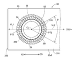
- FIG. 3 is a schematic view of the vicinity of the front end portion 331 of the ground electrode 30 as viewed from the front end side toward the rear end direction BD.
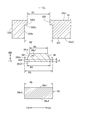
- FIG. 4 is a cross-sectional view of the tip 331 of the ground electrode 30 before laser welding according to the first embodiment. As shown in FIG. 2, the tip portion 331 described above extends in a direction perpendicular to the axis line CL.
- connection end direction CD the direction perpendicular to the axis CL and directed from the axis CL toward the free end 333.
- the front end portion 331 of the ground electrode base material 33 includes a first surface 33 s 1 located on the rear end side, that is, a first surface 33 s 1 facing the center electrode 20 and a first surface 33 s 1. It has the 2nd surface 33s2 which is a back surface, ie, 2nd surface 33s2 located in the front end side.
- a through hole 335 penetrating from the first surface 33 s 1 to the second surface 33 s 2 is formed at a position facing the discharge surface 20 s 1 of the center electrode 20 of the tip 331.
- the through-hole 335 has a small diameter portion 335a having a first diameter R1, and a large diameter having a second diameter R2 that is located on the tip side of the small diameter portion 335a and is larger than the first diameter R1.
- the ground electrode base material 33 is formed with a step portion 335c positioned between the small diameter portion 335a and the large diameter portion 335b in the through hole 335.
- the second diameter R2 (FIG. 4) on the second surface 33s2 is larger than the first diameter R1 (FIG. 4) on the first surface 33s1.
- the ground electrode tip 38 includes a discharge surface 38s1 on the rear end side and a large-diameter surface 38s2 which is the back surface of the discharge surface 38s1 (that is, the front surface side).
- the direction from the large diameter surface 38s2 toward the discharge surface 20s1 (in this embodiment, the rear end direction BD) is also referred to as a first direction, and the opposite direction (in the present embodiment, the front end direction LD) is also referred to as a second direction.
- the discharge surface 38s1 is a surface that forms a gap g between the discharge surface 38s1 and the discharge surface 20s1 of the center electrode 20.
- the ground electrode chip 38 includes a chip body 381 including a discharge surface 38s1 and a flange 382 including a large-diameter surface 38s2 and positioned on the tip side from the chip body 381.
- the diameter of the chip body 381 is linearly reduced from the diameter R5 to the diameter R4 toward the center electrode 20, that is, from the front end side to the rear end side. That is, the chip body 381 has a truncated cone shape having a so-called tapered outer surface 381s.
- the diameter of the flange 382 is larger than the diameter R5 of the tip end of the chip body 381 and the diameter R4 of the rear end.
- the axis CL of the electrode tip is the same as the axis CL of the spark plug 100.
- the diameter R3 (FIG. 4) of the large diameter surface 38s2 is larger than the diameter R4 of the discharge surface 38s1 (the diameter R4 of the rear end of the chip body 381).
- the diameter R4 of the discharge surface 38s1 is smaller than the first diameter R1 (the diameter of the small diameter portion 335a) of the first surface 33s1 of the through hole 335.
- the diameter R3 of the large diameter surface 38s2 is larger than the first diameter R1 of the first surface 33s1 of the through-hole 335 and slightly smaller than the second diameter R2 of the second surface 33s2 (the diameter R2 of the large diameter portion 335b).
- the diameter of the rear end of the flange 382 (the diameter on the discharge surface 38s1 side) is R7.
- the diameter R7 of the rear end of the collar portion 382 is the diameter of the tip of the collar portion 382. It is equal to R3 (the diameter R3 of the large diameter surface 38s2).
- the ratio of the tip diameter R5 of the tip body 381 to the diameter R7 of the flange 382 is 76% or more and 96% or less. 2 and 4, the ratio of the diameter R5 of the tip of the chip body 381 to the diameter R7 is about 80%.
- the diameter R5 of the tip of the chip body 381 is substantially equal to the diameter R1 of the small diameter portion 335a of the through hole 335.
- the ground electrode tip 38 is formed by using an alloy containing a noble metal excellent in spark consumption as a main component.
- the noble metal as the main component is iridium (Ir). Ir has a high melting point among noble metals and is excellent in spark wear resistance. Therefore, it is preferable to form the ground electrode tip 38 using Ir or an iridium alloy containing Ir as a main component.
- a part of the ground electrode tip 38 including the large-diameter surface 38s2 is disposed in the through hole 335, and the discharge surface 20s1 is exposed from the through hole 335 to the center electrode 20 side.
- the entire flange 382 of the ground electrode tip 38 is located on the rear end side in the large diameter portion 335 b of the through hole 335, and most of the tip side of the chip body 381 is the small diameter of the through hole 335.
- a part of the rear end side including the discharge surface 38s1 of the chip body 381 protrudes from the through hole 335 to the rear end side.
- the rear end surface 382s of the flange portion 382 is in contact with the step portion 335c in the through hole 335, and is supported from the rear end side by the step portion 335c.
- the fixing member 39 has a substantially cylindrical outer shape.
- the axis CL of the ground electrode tip 38, the through hole 335, and the fixing member 39 is the same as the axis CL of the spark plug 100.
- the fixing member 39 is disposed in a portion on the tip side of the large-diameter surface 38 s 2 of the ground electrode tip 38 in the large-diameter portion 335 b of the through hole 335.
- the rear end surface 39s1 of the fixing member 39 is in contact with the large diameter surface 38s2 of the ground electrode tip 38. That is, the fixing member 39 supports the ground electrode tip 38 (the flange portion 382) from the tip side.
- the front end surface 39 s 2 of the fixing member 39 is located on substantially the same plane as the second surface 33 s 2 of the ground electrode base material 33.
- the diameter R6 of the fixing member 39 before laser welding is substantially the same as the diameter R2 of the large diameter portion 335b of the through hole 335.
- the ground electrode tip 38 is held by the inner surface of the ground electrode base material 33 that forms the through hole 335 and the rear end surface of the fixing member 39.
- the maximum length L ⁇ b> 1 along the axial direction of the portion disposed in the through hole 335 in the fixing member 39 is a portion where the through hole 335 of the ground electrode base material 33 is formed ( That is, it is 50% or more of the maximum length L2 along the axial direction of the tip portion 331).
- the maximum length L1 is about 60% of the maximum length L2.
- the maximum length L1 is more preferably 60% or more of the maximum length L2, and further preferably 70% or more.
- the bonding strength of the fixing member 39 can be improved.
- the maximum length L1 is always less than 100% of the maximum length L2, and is less than 90% of the maximum length L2 in consideration of the thickness of the ground electrode tip 38.
- the maximum length L ⁇ b> 1 is substantially equal to the length along the axial direction of the fixing member 39. If a part of the fixing member 39 protrudes to the tip side from the second surface 33s2, the maximum length along the axial direction of the fixing member 39 excluding the protruding part is the maximum.
- the length is L1.
- the maximum length L1 can also be said to be the maximum length (distance) along the axial direction from the rear end of the fixing member 39 to the second surface 33s2 of the front end portion 331 of the ground electrode base material 33.
- the maximum length L2 along the axial direction of the portion where the through-hole 335 of the ground electrode base material 33 is formed (that is, the tip portion 331) is the axis line from the first surface 33s1 to the second surface 33s2 of the tip portion 331. It can also be said to be the maximum length (distance) along the direction.
- the boundary BL between the outer side surface 39s3 of the fixing member 39 and the inner side surface of the ground electrode base material 33 that forms the large-diameter portion 335b of the through hole 335 is melted over the entire circumference.
- a portion 82 is formed.
- the hatched portion is a portion of the melted portion 82 that is exposed at the second surface 33 s 2 of the ground electrode base material 33.
- the melting portion 82 is formed by irradiating a laser perpendicular to the second surface 33 s 2 of the ground electrode base material 33.
- the melting portion 82 is a boundary between the outer surface 39 s 3 of the fixing member 39 and the inner surface of the ground electrode base material 33 that forms the large diameter portion 335 b of the through hole 335 in the cross section of FIG. 2. It is provided across the BL.
- the melting portion 82 is a portion including the components of the ground electrode base material 33 and the components of the fixing member 39 that are melted together.
- the ground electrode base material 33 and the fixing member 39 are joined via the melting part 82. Therefore, the melting portion 82 can also be referred to as a joining portion that joins the ground electrode base material 33 and the fixing member 39, and can also be referred to as a bead that joins the ground electrode base material 33 and the fixing member 39.
- the melting portion 82 is formed by being melted at a high temperature.
- the ground electrode base material 33 and the fixing member 39 are different in a fine structure such as a particle diameter, for example.
- the ground electrode 30 is cut, the cross section of FIG. 2 is exposed, and the cross section is subjected to an etching process and then observed, whereby the ground electrode base material 33, the fixing member 39, and the melting portion 82 are observed.
- the boundary can be clearly identified.
- the length (depth) L3 along the axial direction of the melting portion 82 is the maximum length L1 along the axial direction of the portion of the fixing member 39 disposed in the through hole 335. 50% or more.
- the length (depth) L3 along the axial direction of the melting portion 82 is determined from the rear end of the melting portion 82 at the boundary BL between the ground electrode base material 33 and the fixing member 39. It can be defined as the length along the axial direction to the second surface 33s2 of the tip 331.
- the length L3 along the axial direction of the melting part 82 is about 95% of the above-described maximum length L1 of the fixing member 39.
- the length L3 is more preferably 70% or more of the maximum length L1, more preferably 80% or more, still more preferably 90% or more. As the ratio of the length L3 to the maximum length L1 is higher, the bonding strength of the fixing member 39 can be improved.
- the melting portion 82 is connected to the ground electrode over the entire circumference of the boundary BL between the fixing member 39 and the ground electrode base material 33 as can be seen from the portions surrounded by the wavy circles C1 and C2.
- the buttocks 382 of the chip 38 are not reached. That is, the rear end of the melting portion 82 is located on the front end side of the large-diameter surface 38s2 of the ground electrode tip 38 over the entire circumference. In other words, the ratio of the length L3 to the maximum length L1 is less than 100%.
- the maximum length L1 along the axial direction of the portion arranged in the through hole 335 of the fixing member 39 is the through hole of the ground electrode base material 33. From the end on the rear end side of the melted portion 82 at the boundary BL between the ground electrode base material 33 and the fixing member 39, which is 50% or more of the maximum length L2 along the axial direction of the portion where 335 is formed.
- the length L3 along the axial direction to the second surface 33s2 of the tip portion 331 of the ground electrode base material 33 is the maximum length along the axial direction of the portion of the fixing member 39 disposed in the through hole 335. It is 50% or more of the length L1.
- the tip of the spark plug 100 where the fixing member 39 is located is closest to the high temperature portion in the combustion chamber, it becomes extremely hot when the spark plug 100 is used, so that the melting portion 82 and the fixing member 39 are damaged. Easy to receive.
- the spark plug 100 of the first embodiment it is possible to improve the strength particularly in a high temperature environment by ensuring a sufficient length along the axial direction of the melting portion 82.
- the rear end surface 382 s of the flange portion 382 of the ground electrode tip 38 is supported by a step portion 335 c in the through hole 335.
- the rear end surface 382 s of the flange portion 382 and the stepped portion 335 c are in contact with each other, so that the strength with which the ground electrode tip 38 is fixed to the ground electrode base material 33 can be improved.
- the gap (gap) formed between the discharge surface 38 s 1 of the ground electrode tip 38 and the discharge surface 20 s 1 of the center electrode 20 can be prevented from changing during use of the spark plug 100.
- the ratio (R5 / R7) of the diameter R5 of the tip of the chip body 381 to the diameter R7 of the collar part 382 is 76% or more and 95% or less.
- the wear resistance of the spark plug 100 can be improved, and the strength with which the ground electrode tip 38 is fixed to the ground electrode base material 33 can be further improved.
- the ratio (R5 / R7) is 76% or more, the diameter R4 of the discharge surface 20s1 can be suppressed from being excessively reduced, and the diameter R4 of the discharge surface 20s1 can be secured. 100 wear resistance can be improved.
- the ratio (R5 / R7) is 95% or less, the radial width of the flange portion 382 (the width of the rear end surface 382s of the flange portion 382) can be ensured, so that the ground electrode chip 38 is made of the ground electrode base material.
- the strength fixed to 33 can be further improved.
- the ground electrode tip 38 is either iridium or an iridium alloy.
- the strength with which the ground electrode tip 38 is fixed to the ground electrode base material 33 can be further improved.
- FIG. 5 is a flowchart showing an example of a method for manufacturing a spark plug.
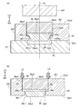
- FIG. 6 is an explanatory diagram of a method for manufacturing the ground electrode 30.
- step S120 an assembly is formed. In the manufacturing process of the spark plug 100 shown in FIG. 1, the assembly includes bending the ground electrode base material 33 of the ground electrode 30 and attaching the ground electrode tip 38 and the fixing member 39 onto the ground electrode base material 33. It is the state before performing.
- a partial cross-sectional view showing the vicinity of the center electrode 20 of the assembly 100x is shown.
- the assembly 100 x includes an insulator 10, a metal shell 50 fixed to the insulator 10, and a center electrode 20 inserted into the shaft hole 12 of the insulator 10.
- a linear ground electrode base material 33 x is joined to the metal shell 50 as the ground electrode base material 33 before being bent.
- Various known methods can be adopted as a method of forming the assembly 100x, and detailed description thereof is omitted.
- the through-hole 335 is formed in the ground electrode base material 33x of the ground electrode 30.
- the shape of the through hole 335 is as described with reference to FIG.
- the through hole 335 is formed in the ground electrode base material 33x before bending using a cutting tool such as a drill.
- step S140 as shown in FIG. 6A, the ground electrode tip 38 and the fixing member 39 are arranged in this order in the formed through-hole 335 in this order (see FIG. 6A). From above). At this time, since the tip body 381 of the ground electrode tip 38 protrudes to the rear end side (lower side of FIG. 6A) from the through hole 335, the ground electrode base material 33x is a support base on which the recess HL is formed. The ground electrode tip 38 and the fixing member 39 are placed in a state of being placed on the ST.
- the front end surface 39s2 of the fixing member 39 is pressed toward the rear end direction BD by the hand press HP. Accordingly, the fixing member 39 is pushed in the rear end direction BD to the position where the flange portion 382 is sandwiched by the rear end surface 39s1 of the fixing member 39 and the stepped portion 335c in the through hole 335.
- the front end surface 39s2 of the fixing member 39 slightly protrudes (for example, 0.1 mm) from the second surface of the front end portion 331 of the ground electrode base material 33 toward the front end side.
- the length of the fixing member 39 along the axial direction is determined so as to be in a state. Thereby, the fixing member 39 can be accurately pushed to a predetermined position by the hand press HP.
- step S160 the fixing member 39 and the ground electrode base material 33 are joined by laser welding.
- An arrow LZ in FIG. 6B conceptually shows laser irradiation for laser welding.
- the laser LZ is irradiated perpendicularly to the second surface 33 s 2 of the ground electrode base material 33 on the boundary BL between the inner surface of the through-hole 335 and the outer surface 39 s 3 of the fixing member 39.
- the laser LZ irradiation is performed over the entire circumference of the boundary BL between the ground electrode base material 33 and the fixing member 39.
- the melting part 82 is formed over the entire circumference of the boundary BL by irradiating the laser LZ at 24 locations at a speed of 12 Hz. As a result, the melting part 82 of FIGS. 2 and 3 is formed.
- step S170 the ground electrode base material 33x is bent to form the gap g. That is, as shown in FIG. 2, the ground electrode base material 33 x is bent toward the center electrode 20 so that the discharge surface 20 s 1 of the center electrode 20 and the discharge surface 38 s 1 of the ground electrode tip 38 face each other.
- the length along the axial direction of the fixing member 39 and the length along the axial direction of the large-diameter portion 335b of the through hole 335 are 1.2 mm, 1.1 mm, and 1 mm, respectively. 0.9 mm, 0.75 mm, and 0.6 mm. Accordingly, in the six types of samples 1 to 6, as shown in Table 1, the maximum length L1 along the axial direction of the portion of the fixing member 39 arranged in the through hole 335 is 1. 2 mm, 1.1 mm, 1 mm, 0.9 mm, 0.75 mm, and 0.6 mm. In addition, the length L3 along the axial direction of the melting part 82 was adjusted to 50% of the length L1.
- the ratio of the length L1 to the length L2 (L1 / L2) is 80% and 73.3%, respectively. , 66.7%, 60%, 50%, and 40%.
- Samples 1 to 6 were subjected to a high temperature strength test.
- the vicinity of the fixing member 39 of each sample was heated to 1050 degrees Celsius using a high frequency heating apparatus.
- a load of 1000 N was applied to the rear end surface 39s1 of the fixing member 39 toward the front end direction LD using a metal rod.
- each sample was observed from the second surface 33 s 2 side of the ground electrode base material 33, and it was confirmed whether or not the fracture occurred in the melted portion 82.
- the evaluation of the sample in which the fracture of the melting part 82 occurs was “B”, and the evaluation of the sample in which the fracture of the melting part 82 did not occur was “A”.
- the results of the evaluation are as shown in Table 1.
- the evaluation of the sample in which the ratio of the length L1 to the length L2 (L1 / L2) is less than 50%, that is, the sample 6 in which (L1 / L2) is 40% was “B”.
- (L1 / L2) By setting (L1 / L2) to 50% or more, the length in the axial direction of the boundary BL between the fixing member 39 and the ground electrode base material 33 can be increased, whereby the length of the melting portion 82 in the axial direction can be increased.
- the length can be increased. This is considered to be because the strength at which the fixing member 39 is joined to the ground electrode base material 33 can be improved.
- the length L3 along the axial direction of the melting portion 82 is 0.3 mm, 0.45 mm, 0.6 mm, 0.75 mm, and 0.9 mm. It was done. Accordingly, in the five types of samples 7 to 11, the ratio of the length L3 to the length L1 (L3 / L1) is 33.3%, 50%, 66.7%, 83.3%, and 100%, respectively. Has been adjusted. The configuration of the other parts of these samples is the same as that of the sample 4 of the first evaluation test.
- each sample was observed from the second surface 33 s 2 side of the ground electrode base material 33, and it was confirmed whether or not the fracture occurred in the melted portion 82.
- the evaluation of the sample in which the fracture of the melting part 82 occurs was “B”, and the evaluation of the sample in which the fracture of the melting part 82 did not occur was “A”.
- the results of the evaluation are as shown in Table 2.
- the evaluation of the sample in which the ratio of the length L3 to the length L1 (L3 / L1) is less than 50%, that is, the sample 7 in which (L3 / L1) is 33.3% was “B”.
- the evaluation of samples 8 to 11 in which (L3 / L1) is 50% or more, that is, samples 8 to 11 in which (L3 / L1) is 50%, 66.7%, 83.3%, and 100% is “A”.
- Met By setting (L3 / L1) to 50% or more, the length of the melting portion 82 in the axial direction can be increased. This is considered to be because the strength at which the fixing member 39 is joined to the ground electrode base material 33 can be improved.
- the maximum length L1 along the axial direction of the portion of the fixing member 39 disposed in the through hole 335 is the axial direction of the tip portion 331 of the ground electrode base material 33.
- the axial line from the rear end of the melted portion 82 at the boundary between the ground electrode base material 33 and the fixing member 39 to the second surface 33s2 of the ground electrode base material 33 is 50% or more of the maximum length L2 along
- the length L3 along the direction is preferably 50% or more of the maximum length L1 along the axial direction of the portion of the fixing member 39 disposed in the through hole 335, from the viewpoint of improving the strength. I was able to confirm.
- the diameter R7 of the flange portion 382 has a common value of 3.3 mm, and as shown in Table 3, the diameter R5 of the tip of the chip body 381 is 2 mm and 2.3 mm, respectively. , 2.5 mm, 2.7 mm, 2.9 mm, 3.15 mm, and 3.2 mm, samples 12 to 18 of the seven types of ground electrode chips 38 were fabricated. In addition, the length along the axial direction of the chip body 381 was a common value of 0.4 mm for each sample.
- the tip diameter R5 of the tip body 381 is adjusted to adjust the ratio of the tip diameter R5 of the tip body 381 to the diameter R7 of the flange 382 (R5 / R7). ) Are adjusted to 61%, 70%, 76%, 82%, 88%, 95% and 97%, respectively.
- the strength test and the wear resistance test were performed on the samples 12 to 18 of the ground electrode tip 38, respectively.
- each sample of the ground electrode tip 38 is fitted to the ground electrode base material 33 in which the corresponding shape of the through hole 335 is formed, and each sample (the ground electrode tip 38 is used). ) was loaded with a load of 150 N (Newton) toward the rear end direction BD.
- the results of the evaluation are as shown in Table 3.
- the evaluation of the sample 18 in which the ratio (R5 / R7) of the diameter R5 of the tip of the tip body 381 to the diameter R7 of the flange 382 is greater than 95%, that is, the sample 18 in which (R5 / R7) is 97% is “B "Met.
- the evaluation of samples 12 to 17 in which (R5 / R7) is 95% or less, that is, samples 12 to 17 in which (R5 / R7) is 61%, 70%, 76%, 82%, 88%, 95% is “ A ".
- the spark plug 100 was assembled using each sample of the ground electrode tip 38. And the test which ignites the ignition plug of each sample 60 times per second in the chamber of the nitrogen gas atmosphere of atmospheric pressure 0.6MPa was implemented over 500 hours. In each sample, the initial gap was set to 0.3 mm.
- the ratio of the diameter R5 of the rear end of the chip body 381 to the diameter R7 of the flange 382 is preferably 76% or more and 95% or less from the viewpoint of improving strength and improving wear resistance. I was able to confirm.
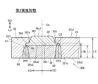
- FIG. 7 is an enlarged partial cross-sectional view showing the vicinity of the tip 331b of the ground electrode 30b of the spark plug according to the second embodiment.
- the partial cross-sectional view of FIG. 7 is a cross-section passing through the axis CL of the fixing member 39 and along the axial direction, similarly to FIG.
- the melting portion 82 does not reach the flange 382 of the ground electrode tip 38 over the entire circumference of the boundary BL between the fixing member 39 and the ground electrode base material 33.
- the melting portion 82 reaches the flange portion 382 of the ground electrode tip 38 at a part of the boundary BL between the fixing member 39 and the ground electrode base material 33, and the ground portion at the other portion. It does not reach the flange 382 of the electrode tip 38.
- Other configurations of the second embodiment are the same as those of the first embodiment. Further details will be described below.
- a virtual line extending in the free end direction FD from the axis line CL of the electrode tip 38 is defined as a first line VL 1
- the axis line of the electrode tip 38 A virtual line extending from CL to the connection end direction CD is defined as a second line VL2.
- a portion intersecting with the first line VL 1 in the melting portion 82 shown by hatching in FIG. A portion intersecting with the second line VL2 is defined as a second portion PT2.
- the melting part 82 does not reach the collar part 382 of the ground electrode tip 38 (FIG. 2).
- the melting portion 82 reaches the flange portion 382 of the ground electrode tip 38 in the first portion PT1, as in the first embodiment. Not done.
- the melting portion 82 is different from the first embodiment in the flange portion 382 of the ground electrode tip 38. Has reached.
- the rear end of the melting portion 82 in the first portion PT1 is positioned on the front end side of the large-diameter surface 38s2 of the ground electrode tip 38, and the rear end of the melting portion 82 in the second portion PT2. Is located on the rear end side of the large-diameter surface 38s2 of the ground electrode tip 38.
- the melting portion 82 reaches the flange portion 382 of the electrode tip 38 within the range of the angle ⁇ in the circumferential direction around the second portion PT ⁇ b> 2 of the melting portion 82. Yes. Outside the range of the angle ⁇ in the circumferential direction, the melting part 82 does not reach the flange part 382 of the electrode tip 38.
- the angle ⁇ indicating the range of the melted part 82 reaching the electrode tip 38 is preferably, for example, more than 0 degree and less than 160 degrees, and more preferably 30 degrees or more and less than 120 degrees.
- the length L3b (FIG. 7) along the axial direction of the melting portion 82 exceeds 100% of the maximum length L1 of the fixing member 39. That is, in the second embodiment, the ratio (L3b / L1) of the length L3b to the maximum length L1 described above exceeds 100%. For example, in the example of FIG. 7, the ratio (L3b / L1) of the length L3b to the maximum length L1 is more than 100% and less than 120%.
- connection end 332 is connected to the metal shell 50 on the connection end 332 side of the ground electrode base material 33, heat sinking is good.
- the melting portion 82 at the position intersecting the first line VL1 extending in the connection end direction CD from the center of the ground electrode tip 38 toward the connection end 332 is the ground electrode tip 38. Has reached. For this reason, heat is easily transmitted from the ground electrode tip 38 heated to the spark or the fuel gas ignited by the spark to the connection end 332 side of the ground electrode base material 33 through the melting portion 82.
- the thermal conductivity is reduced at the interface between the ground electrode tip 38 and the ground electrode base material 33.
- heat is less likely to be transmitted from the ground electrode tip 38 to the connection end side of the ground electrode base material 33.
- the heat-drawing performance of the spark plug 100 can be improved, and the ground electrode tip 38 can be prevented from becoming excessively hot.
- the wear resistance of the ground electrode tip 38 deteriorates as the temperature of the ground electrode tip 38 increases.
- the wear resistance of the ground electrode tip 38 can be improved.
- the heat absorption is poor and the temperature tends to be high. If the melting part 82 near the free end 333 that tends to become high temperature reaches the ground electrode tip 38, cracks are likely to occur in the melting part 82 due to thermal stress. This is because the ground electrode tip 38 and the ground electrode base material 33 are made of different materials, and therefore have different linear expansion coefficients, so that thermal stress is generated at the joint portion in a high temperature environment.
- the melting portion 82 at a position intersecting the second line VL ⁇ b> 2 extending in the direction from the center of the ground electrode tip 38 toward the free end 333 does not reach the ground electrode tip 38.
- the occurrence of cracks in the melted portion 82 due to thermal stress can be suppressed.
- the durability of the spark plug in a high temperature environment can be improved.
- the melting portion 82 is formed over the entire circumference of the boundary BL between the fixing member 39 and the ground electrode base material 33.
- the melted portion is not limited to this, and may be formed in a part of the circumferential direction of the boundary BL between the fixing member 39 and the ground electrode base material 33 and may not be formed in the other part.
- the melting portion 82 is divided into a plurality at predetermined intervals (for example, intervals of 30 degrees or 60 degrees) along the circumferential direction of the boundary BL between the fixing member 39 and the ground electrode base material 33. It may be divided.
- the shape of the ground electrode tip 38 shown in each of the above embodiments is an example, and is not limited thereto.
- the flange portion 382 of the ground electrode tip 38 may be omitted, and the ground electrode tip 38 may be only the tip body 381 having a tapered shape (conical truncated cone shape).
- the small diameter portion 335 a of the through hole 335 may be reduced in diameter from the front end side toward the rear end direction BD corresponding to the outer shape of the chip body 381.
- the chip body 381 may have a cylindrical shape instead of a tapered shape.
- the shape of the fixing member 39 shown in each of the above embodiments is an example, and is not limited thereto.
- the shape of the fixing member 39 may have a tapered shape that decreases in diameter from the front end side toward the rear end direction BD.
- the shape of the large-diameter portion 335 b of the through hole 335 only needs to have a tapered shape corresponding to the shape of the fixing member 39.
- the melting portion 82 is formed so as to extend obliquely with respect to the second surface 33 s 2 of the ground electrode base material 33 corresponding to the boundary between the fixed member 39 having a tapered shape and the large diameter portion 335 b. Also good.
- the shape of the fixing member 39 viewed from the rear end side toward the front end direction LD may not be a circle but may be another shape.
- the shape of the fixing member 39 viewed from the rear end side toward the front end direction LD may be an ellipse in which the length in the free end direction FD is longer than the length in the direction orthogonal to the free end direction FD.
- the fixing member 39 is formed using NCF600 or NCF601, but may be formed using another heat-resistant material, for example, a heat-resistant nickel alloy different from NCF600 or NCF601.
- the ground electrode tip 38 is made of an iridium alloy, but may be made of a noble metal different from iridium or an alloy containing the noble metal as a main component.
- a noble metal different from iridium for example, platinum (Pt) or rhodium (Rh) may be employed.
- the configuration of the spark plug is not limited to the configuration described in FIG. 1, and various configurations can be employed.
- an electrode tip may be provided in a portion of the center electrode 20 where the gap g is formed.
- an alloy containing a noble metal such as iridium or platinum can be used.
- the core material 22 of the center electrode 20 may be omitted.
Landscapes
- Engineering & Computer Science (AREA)
- Manufacturing & Machinery (AREA)
- Spark Plugs (AREA)
Abstract
La présente invention empêche une puce d'électrode de masse de tomber d'un matériau de base d'électrode de masse. La bougie d'allumage de l'invention comporte : une électrode centrale ; un matériau de base d'électrode de masse qui présente une première surface et une seconde surface et qui a un trou traversant pénétrant de la première surface vers la seconde surface ; une puce d'électrode de masse qui possède une surface de décharge électrique et une surface de grand diamètre qui est la face arrière de la surface de décharge électrique et dont une partie, comprenant la surface de grand diamètre, est disposée à l'intérieur du trou traversant, tandis que la surface de décharge électrique est exposée depuis le trou traversant vers le côté électrode centrale ; et un élément de fixation qui, lorsque la direction allant de la surface de grand diamètre vers la surface de décharge électrique est définie en tant que première direction, tandis que la direction inverse est définie en tant que seconde direction, est disposé au niveau d'une portion sur le côté de seconde direction de la surface de grand diamètre dans le trou traversant. La longueur maximale dans la première direction de la portion de l'élément de fixation disposée à l'intérieur du trou traversant repose de façon à traverser l'axe central de l'élément de fixation. Dans une section transversale le long de la première direction, la longueur dans la première direction vers la seconde surface à partir d'une extrémité dans la première direction d'une partie de soudage à la limite entre le matériau de base d'électrode de masse et l'élément de fixation est d'au moins 50 % de la longueur maximale dans la première direction de la portion de l'élément de fixation disposée à l'intérieur du trou traversant.
Priority Applications (3)
| Application Number | Priority Date | Filing Date | Title |
|---|---|---|---|
| US16/062,357 US10270227B2 (en) | 2015-12-16 | 2016-10-11 | Ignition plug |
| CN201680073887.4A CN108475899A (zh) | 2015-12-16 | 2016-10-11 | 火花塞 |
| DE112016005813.6T DE112016005813T5 (de) | 2015-12-16 | 2016-10-11 | Zündkerze |
Applications Claiming Priority (2)
| Application Number | Priority Date | Filing Date | Title |
|---|---|---|---|
| JP2015245619A JP6270802B2 (ja) | 2015-12-16 | 2015-12-16 | 点火プラグ |
| JP2015-245619 | 2015-12-16 |
Publications (1)
| Publication Number | Publication Date |
|---|---|
| WO2017104097A1 true WO2017104097A1 (fr) | 2017-06-22 |
Family
ID=59056192
Family Applications (1)
| Application Number | Title | Priority Date | Filing Date |
|---|---|---|---|
| PCT/JP2016/004542 Ceased WO2017104097A1 (fr) | 2015-12-16 | 2016-10-11 | Bougie d'allumage |
Country Status (5)
| Country | Link |
|---|---|
| US (1) | US10270227B2 (fr) |
| JP (1) | JP6270802B2 (fr) |
| CN (1) | CN108475899A (fr) |
| DE (1) | DE112016005813T5 (fr) |
| WO (1) | WO2017104097A1 (fr) |
Families Citing this family (3)
| Publication number | Priority date | Publication date | Assignee | Title |
|---|---|---|---|---|
| WO2021140756A1 (fr) * | 2020-01-10 | 2021-07-15 | 日本特殊陶業株式会社 | Bougie d'allumage |
| DE102020211897A1 (de) | 2020-09-23 | 2022-03-24 | Robert Bosch Gesellschaft mit beschränkter Haftung | Zündkerzenelektrode sowie Zündkerze mit der Zündkerzenelektrode und Herstellungsverfahren für die Zündkerzenelektrode |
| DE102023201527A1 (de) * | 2023-02-21 | 2024-08-22 | Robert Bosch Gesellschaft mit beschränkter Haftung | Zündkerze mit Vorsprung an einer brennraumseitigen ebenen Gehäusestirnfläche |
Citations (2)
| Publication number | Priority date | Publication date | Assignee | Title |
|---|---|---|---|---|
| JPS5940482A (ja) * | 1982-08-30 | 1984-03-06 | 日本特殊陶業株式会社 | スパ−クプラグ |
| JPS62268079A (ja) * | 1986-05-13 | 1987-11-20 | 株式会社デンソー | 内燃機関用スパ−クプラグ |
Family Cites Families (4)
| Publication number | Priority date | Publication date | Assignee | Title |
|---|---|---|---|---|
| JP2002280145A (ja) | 2001-03-19 | 2002-09-27 | Ngk Spark Plug Co Ltd | スパークプラグ及びその製造方法 |
| US20100264801A1 (en) * | 2007-12-20 | 2010-10-21 | Tomoo Tanaka | Spark plug and process for producing the spark plug |
| CN103155314B (zh) * | 2010-09-29 | 2014-10-08 | 日本特殊陶业株式会社 | 火花塞 |
| JP6328088B2 (ja) * | 2015-11-06 | 2018-05-23 | 日本特殊陶業株式会社 | スパークプラグ |
-
2015
- 2015-12-16 JP JP2015245619A patent/JP6270802B2/ja not_active Expired - Fee Related
-
2016
- 2016-10-11 DE DE112016005813.6T patent/DE112016005813T5/de not_active Ceased
- 2016-10-11 US US16/062,357 patent/US10270227B2/en not_active Expired - Fee Related
- 2016-10-11 WO PCT/JP2016/004542 patent/WO2017104097A1/fr not_active Ceased
- 2016-10-11 CN CN201680073887.4A patent/CN108475899A/zh not_active Withdrawn
Patent Citations (2)
| Publication number | Priority date | Publication date | Assignee | Title |
|---|---|---|---|---|
| JPS5940482A (ja) * | 1982-08-30 | 1984-03-06 | 日本特殊陶業株式会社 | スパ−クプラグ |
| JPS62268079A (ja) * | 1986-05-13 | 1987-11-20 | 株式会社デンソー | 内燃機関用スパ−クプラグ |
Also Published As
| Publication number | Publication date |
|---|---|
| US20180375300A1 (en) | 2018-12-27 |
| US10270227B2 (en) | 2019-04-23 |
| CN108475899A (zh) | 2018-08-31 |
| JP6270802B2 (ja) | 2018-01-31 |
| JP2017111982A (ja) | 2017-06-22 |
| DE112016005813T5 (de) | 2018-08-30 |
Similar Documents
| Publication | Publication Date | Title |
|---|---|---|
| JP6855354B2 (ja) | 点火プラグ | |
| JP7198907B2 (ja) | スパークプラグ | |
| JP4625531B1 (ja) | スパークプラグ | |
| JP6270802B2 (ja) | 点火プラグ | |
| KR101118401B1 (ko) | 스파크 플러그 | |
| JP6611769B2 (ja) | 点火プラグ | |
| KR101998536B1 (ko) | 스파크 플러그 | |
| JP6548610B2 (ja) | プラズマジェットプラグ | |
| US9742157B2 (en) | Spark plug | |
| JP5895056B2 (ja) | スパークプラグ | |
| WO2009116553A1 (fr) | Bougie d'allumage | |
| JP6293107B2 (ja) | 点火プラグ | |
| JP6910992B2 (ja) | イグナイタプラグ | |
| JP7039519B2 (ja) | 点火プラグ | |
| JP2017111981A (ja) | 点火プラグ | |
| JP6707404B2 (ja) | スパークプラグ | |
| JP2020191227A (ja) | 内燃機関、および、点火プラグ |
Legal Events
| Date | Code | Title | Description |
|---|---|---|---|
| 121 | Ep: the epo has been informed by wipo that ep was designated in this application |
Ref document number: 16875088 Country of ref document: EP Kind code of ref document: A1 |
|
| WWE | Wipo information: entry into national phase |
Ref document number: 112016005813 Country of ref document: DE |
|
| 122 | Ep: pct application non-entry in european phase |
Ref document number: 16875088 Country of ref document: EP Kind code of ref document: A1 |