WO2017104194A1 - Dispositif et procédé de lavage, et bioréacteur de séparation par membrane - Google Patents
Dispositif et procédé de lavage, et bioréacteur de séparation par membrane Download PDFInfo
- Publication number
- WO2017104194A1 WO2017104194A1 PCT/JP2016/076901 JP2016076901W WO2017104194A1 WO 2017104194 A1 WO2017104194 A1 WO 2017104194A1 JP 2016076901 W JP2016076901 W JP 2016076901W WO 2017104194 A1 WO2017104194 A1 WO 2017104194A1
- Authority
- WO
- WIPO (PCT)
- Prior art keywords
- cleaning
- ultrasonic
- output value
- ultrasonic wave
- controller
- Prior art date
- Legal status (The legal status is an assumption and is not a legal conclusion. Google has not performed a legal analysis and makes no representation as to the accuracy of the status listed.)
- Ceased
Links
Images








Classifications
-
- B—PERFORMING OPERATIONS; TRANSPORTING
- B08—CLEANING
- B08B—CLEANING IN GENERAL; PREVENTION OF FOULING IN GENERAL
- B08B3/00—Cleaning by methods involving the use or presence of liquid or steam
- B08B3/04—Cleaning involving contact with liquid
- B08B3/10—Cleaning involving contact with liquid with additional treatment of the liquid or of the object being cleaned, e.g. by heat, by electricity or by vibration
- B08B3/12—Cleaning involving contact with liquid with additional treatment of the liquid or of the object being cleaned, e.g. by heat, by electricity or by vibration by sonic or ultrasonic vibrations
-
- Y—GENERAL TAGGING OF NEW TECHNOLOGICAL DEVELOPMENTS; GENERAL TAGGING OF CROSS-SECTIONAL TECHNOLOGIES SPANNING OVER SEVERAL SECTIONS OF THE IPC; TECHNICAL SUBJECTS COVERED BY FORMER USPC CROSS-REFERENCE ART COLLECTIONS [XRACs] AND DIGESTS
- Y02—TECHNOLOGIES OR APPLICATIONS FOR MITIGATION OR ADAPTATION AGAINST CLIMATE CHANGE
- Y02W—CLIMATE CHANGE MITIGATION TECHNOLOGIES RELATED TO WASTEWATER TREATMENT OR WASTE MANAGEMENT
- Y02W10/00—Technologies for wastewater treatment
- Y02W10/10—Biological treatment of water, waste water, or sewage
Definitions
- the present invention relates to a cleaning apparatus and a cleaning method for cleaning a cleaning object installed in a cleaning tank, and a membrane separation bioreactor.
- microbubbles those having a diameter of less than 1 mm are called microbubbles, and are applied to processes in various fields described above.
- the fine bubbles containing the microbubbles have a small buoyancy in the liquid compared to normal bubbles having a diameter of 1 mm or more, and can remain in the liquid for a long time. Further, the fine bubbles have a property of adsorbing dirt on the gas-liquid interface, and in particular, fine bubbles having a bubble diameter of 100 ⁇ m or less are said to have a higher cleaning effect. Therefore, in the cleaning field, a method of cleaning a cleaning object by applying the property of fine bubbles that adsorb dirt is proposed and put into practical use.
- ultrasonic waves are conventionally used in industrial cleaning, and cleaning parts such as machined parts and semiconductors can be cleaned by using cavitation of bubbles generated by ultrasonic vibration.
- cleaning parts such as machined parts and semiconductors
- cavitation of bubbles generated by ultrasonic vibration For example, when cleaning processing oil adhering to machined parts, it is common to use ultrasonic waves and cleaning agents in combination, but in recent years, there is a tendency to reduce cleaning agents due to environmental damage problems. .
- the amount of the cleaning agent is reduced, the cleaning power decreases, so it is necessary to increase the ultrasonic intensity to ensure the cleaning power.
- cleaning with fine bubbles can reduce the amount of cleaning agent used and reduce damage to the cleaning object, but it is difficult to ensure sufficient cleaning power.
- Patent Document 1 describes a cleaning method using ultrasonic waves and fine bubbles. In this method, water containing fine bubbles is filled in the washing tank, and ultrasonic waves are generated in the washing tank to forcibly vibrate the fine bubbles, thereby rubbing off dirt adhering to the surface of the washing object. Can do.
- Patent Document 2 describes a method in which fine bubbles are uniformly dispersed in a cleaning tank and the cleaning power is improved without damaging the cleaning object.
- Patent Document 3 describes a method of cleaning while controlling ultrasonic output based on detection values of a sound pressure sensor and a temperature sensor provided in a cleaning tank, and reducing damage to an object to be cleaned by ultrasonic waves. Has been.
- the ultrasonic output can be adjusted based on the sound pressure in the cleaning tank so as not to cause damage to the cleaning object.
- the cleaning power is reduced at a portion where the sound pressure in the cleaning tank is low, that is, a portion where the ultrasonic wave does not act.
- the present invention has been made in view of the above-described problems in the prior art, and is capable of uniformly cleaning a cleaning object while suppressing damage to the cleaning object, and a film.
- An object is to provide a separation bioreactor.
- the cleaning apparatus of the present invention is the cleaning apparatus for cleaning a cleaning object installed between the liquid level of the cleaning liquid in the cleaning tank storing the cleaning liquid and the bottom surface of the cleaning tank using ultrasonic waves.
- An ultrasonic generator that outputs the ultrasonic waves in the tank, a bubble generator that generates bubbles and adds the bubbles to the cleaning liquid, a detector that detects the ultrasonic waves, and an output value of the ultrasonic waves
- a controller that performs control to switch between a first output value at which gaseous cavitation occurs and a second output value at which vapor cavitation occurs, wherein the ultrasonic generator has the second output value
- the ultrasonic wave is output to the bubble added by the bubble generator, and the output value of the ultrasonic wave is switched from the second output value based on the control of the controller, and the ultrasonic wave having the first output value To the washed object It is intended to.
- the cleaning method of the present invention is a cleaning method for cleaning a cleaning object installed between a liquid surface of the cleaning liquid in a cleaning tank storing a cleaning liquid and a bottom surface of the cleaning tank using ultrasonic waves
- An ultrasonic wave generating step for outputting the ultrasonic wave in the cleaning tank, a bubble generating step for generating bubbles and adding the bubbles to the cleaning liquid, and an output value of the ultrasonic waves are generated by a first cavitation.
- a first setting step for setting the output value; a second setting step for setting the output value of the ultrasonic wave to a second output value in which vapor cavitation occurs; and the ultrasonic wave having the second output value is converted into the bubble.
- a first output step for outputting the first output value, a switching step for switching the set second output value to the first output value, and outputting the ultrasonic wave having the first output value to the cleaning object. And it has a second output step.
- the membrane separation bioreactor of the present invention is a membrane separation bioreactor that separates water to be treated in a treatment tank with a separation membrane, and a diffuser that generates air bubbles and diffuses the separation membrane;
- An ultrasonic generator that outputs ultrasonic waves into the processing tank, a detector that detects the ultrasonic waves, and an output value of the ultrasonic waves are a first output value that causes gaseous cavitation and a first that causes vapor cavitation.
- a controller that performs control to switch between two output values, and the ultrasonic generator outputs the ultrasonic wave having the second output value to the bubbles, based on the control of the controller The output value of the ultrasonic wave is switched from the second output value, and the ultrasonic wave having the first output value is output to the separation membrane.
- the cleaning object by adjusting the ultrasonic output based on the positional relationship between the cleaning object and the antinode position and node position of the standing wave, the cleaning object can be reduced while suppressing damage to the cleaning object. It becomes possible to wash uniformly.
- FIG. 2 is a schematic diagram illustrating an example of a configuration of a cleaning device according to Embodiment 1.
- FIG. It is the schematic for demonstrating the sound pressure distribution of the ultrasonic wave in the washing tank in the washing
- FIG. 2 It is a flowchart which shows an example of the flow of the washing process by the washing
- FIG. 2 is a schematic diagram for explaining a cleaning method when a cleaning object is installed at either one of an antinode position and a node position of a standing wave in the cleaning apparatus of FIG. 1.
- FIG. 2 is a schematic diagram for explaining a cleaning method in the case where the installation position of the cleaning object includes an antinode position and a node position of a standing wave in the cleaning apparatus of FIG. 1.
- FIG. 6 is a schematic diagram illustrating an example of a configuration of a cleaning device according to a second embodiment.
- FIG. 6 is a schematic diagram illustrating an example of a configuration of a cleaning device according to a third embodiment.
- FIG. 6 is a schematic diagram illustrating an example of a configuration of a cleaning device according to a fourth embodiment.
- FIG. 10 is a schematic diagram illustrating an example of a configuration of a cleaning device according to a fifth embodiment.
- FIG. 10 is a schematic diagram illustrating an example of a configuration of a cleaning device according to a sixth embodiment.
- FIG. 10 is a schematic diagram illustrating an example of a configuration of a cleaning device according to a seventh embodiment.
- FIG. 10 is a schematic diagram illustrating an example of a configuration of a cleaning device according to an eighth embodiment.
- Embodiment 1 FIG.
- the cleaning apparatus according to Embodiment 1 of the present invention will be described.
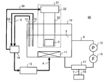
- FIG. 1 is a schematic diagram illustrating an example of the configuration of the cleaning apparatus 1 according to the first embodiment.
- the cleaning apparatus 1 includes a cleaning tank 10, an ultrasonic generator 11, an ultrasonic oscillator 12, an ultrasonic detector 13, a controller 14, a pump 15, a filter 16, a fine bubble generator 17, a gas.
- a supply source 18 is included.
- the cleaning tank 10 can store the cleaning liquid 2 therein and cleans the cleaning object 3 disposed in the cleaning liquid 2.
- the ultrasonic generator 11 is provided at the bottom of the cleaning tank 10.
- the ultrasonic generator 11 generates ultrasonic waves based on the frequency, sound pressure, and the like set by an ultrasonic oscillator 12 described later, and irradiates the generated ultrasonic waves toward the liquid surface of the cleaning liquid 2, for example.
- the ultrasonic oscillator 12 is connected to the ultrasonic generator 11 via the ultrasonic output line 4.
- the ultrasonic oscillator 12 sets the frequency, sound pressure, and the like of ultrasonic waves generated from the ultrasonic generator 11 based on the control of the controller 14 described later.
- the ultrasonic detector 13 is provided in the cleaning tank 10.
- the ultrasonic detector 13 detects the characteristics of ultrasonic waves including at least the sound pressure of the ultrasonic waves emitted from the ultrasonic generator 11.
- the example of detection by the ultrasonic detector 13 is not limited to this, and the ultrasonic detector 13 may simultaneously or at least one or more characteristics related to a plurality of ultrasonic waves such as ultrasonic energy, sound pressure, and frequency. May be detected.
- the controller 14 is connected to the ultrasonic oscillator 12 and the ultrasonic detector 13 via the control line 5.
- the controller 14 controls the ultrasonic oscillator 12 based on information about ultrasonic waves such as ultrasonic energy, sound pressure, and frequency detected by the ultrasonic detector 13.
- the pump 15 is connected to the cleaning tank 10 via the liquid pipe 6 and is provided for circulating the cleaning liquid 2 in the cleaning tank 10.
- the filter 16 is connected to the pump 15 via the liquid pipe 6.
- the filter 16 is provided, for example, to remove foreign matters such as dirt attached to the cleaning object 3 contained in the cleaning liquid 2 flowing through the liquid pipe 6.
- the fine bubble generator 17 is connected to the filter 16 and the cleaning tank 10 through the liquid pipe 6.
- the fine bubble generator 17 is connected to a gas supply source 18 to be described later via the intake pipe 7.
- the fine bubble generator 17 generates fine bubbles using the gas supplied from the gas supply source 18 and adds the generated fine bubbles to the cleaning liquid 2 flowing through the liquid pipe 6.
- the fine bubble generator 17 adds the fine bubbles to the inflowing cleaning liquid 2 and then causes the cleaning liquid 2 to flow out into the cleaning tank 10.
- the bubble diameter of the fine bubble in this invention is preferable in a diameter being 1 mm or less, for example. This is because by setting the diameter of the fine bubbles to 1 mm or less, it can be applied to the cleaning of various cleaning objects such as semiconductors, electronic parts, medical instruments and the like.
- the fine bubble generator 17 is preferably an ejector system, for example. This is because there is an advantage that power is not required, low cost, small size, easy installation, and adjustment of the intake air amount, bubble diameter, etc. is easy.
- the gas supply source 18 is connected to the fine bubble generator 17 via the intake pipe 7 and supplies a gas such as air to the fine bubble generator 17.
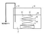
- FIG. 2 is a schematic view for explaining the sound pressure distribution of ultrasonic waves in the cleaning tank 10 in the cleaning apparatus 1 of FIG.
- an ultrasonic wave 81 is irradiated from the ultrasonic generator 11 toward the liquid surface 80, and most of the ultrasonic wave 81, for example, 99% or more is reflected by the liquid surface 80 of the cleaning liquid 2 to generate ultrasonic waves. Proceed in the direction of vessel 11. Next, the ultrasonic wave 81 traveling in the direction of the ultrasonic generator 11 is further reflected by the ultrasonic generator 11 and travels again in the direction of the liquid level 80. Then, the ultrasonic wave 81 traveling in the direction of the liquid level 80 from the ultrasonic generator 11 and the ultrasonic wave 81 traveling in the direction of the ultrasonic generator 11 from the liquid level 80 interfere with each other and are synthesized.
- a standing wave is generated by the ultrasonic wave 81 irradiated from the ultrasonic generator 11, and in the cleaning liquid 2, the position where the sound pressure is highest and the position where the sound pressure is lowest are constant in the vertical direction. It is distributed alternately at a distance interval of.
- antinode 82 The position where the sound pressure is highest in such a standing wave is referred to as an antinode 82.
- the pressure fluctuation due to the ultrasonic wave 81 is maximized, so that cavitation occurs.
- Cavitation includes gaseous cavitation and vapor cavitation.
- Gaseous cavitation occurs when the ultrasonic output is small, that is, when the pressure fluctuation of the ultrasonic wave 81 is small. Gaseous cavitation has the effect that shock waves are less likely to occur.
- Vapor cavitation is a shock wave with high energy, and occurs when the ultrasonic output is large, that is, when the pressure fluctuation of the ultrasonic wave 81 is large. Vapor cavitation has a large energy, so that the cleaning power is improved, but it causes damage to the cleaning object 3. On the other hand, the shock wave caused by vapor cavitation has an effect of crushing and miniaturizing bubbles present in the cleaning liquid 2.
- bubbles are refined using a shock wave or ultrasonic energy generated by vapor cavitation. Thereafter, the ultrasonic output is reduced to change to gas cavitation, and cleaning is performed using shock waves or ultrasonic energy generated by the gas cavitation and fine bubbles.
- the sound pressure as the ultrasonic output is set to an output that causes gaseous cavitation at the abdominal position 82.
- a boundary value between an ultrasonic output value at which gaseous cavitation occurs and an ultrasonic output value at which vapor cavitation occurs is referred to as a “cavitation threshold”.
- the position where the sound pressure is lowest in the standing wave is referred to as a node position 83.
- the pressure fluctuation due to the ultrasonic wave 81 is minimized, so that not only vapor cavitation but also gaseous cavitation hardly occurs. Therefore, at this node position 83, it is difficult to clean the cleaning object 3 by cavitation.
- the sound pressure as the ultrasonic output is set to an output that causes vapor cavitation at the abdominal position 82.
- bubbles are refined using shock waves or ultrasonic energy generated by vapor cavitation. Thereafter, the ultrasonic output is reduced to change to gas cavitation, and cleaning is performed using shock waves or ultrasonic energy generated by the gas cavitation and fine bubbles.
- the ultrasonic wave 81 repeats reflection between the liquid level 80 and the ultrasonic wave generator 11, the ultrasonic wave 81 irradiated from the ultrasonic wave generator 11 at a certain time has the energy of the cleaning liquid over time. Dissipates into 2 and decays. However, the standing wave in the cleaning liquid 2 does not disappear while the ultrasonic wave 81 is continuously applied from the ultrasonic generator 11.
- the antinode position 82, the node position 83, and the cavitation threshold of the standing wave by the ultrasonic wave 81 vary depending on the use environment such as the frequency of the ultrasonic wave 81, the type of the cleaning liquid 2, the temperature of the cleaning liquid 2, and the atmospheric pressure. Therefore, when cleaning the cleaning object 3, it is preferable to investigate these usage environments in advance through experiments or the like.
- the cleaning apparatus 1 generates a standing wave in the cleaning liquid 2 in the cleaning tank 10 by generating an ultrasonic wave 81 from the ultrasonic generator 11.
- standing wave energy, sound pressure, and the like at the position where the cleaning object 3 is installed are detected by the ultrasonic detector 13.
- the controller 14 controls the ultrasonic oscillator 12 to adjust the output of the ultrasonic wave 81 generated from the ultrasonic wave generator 11.
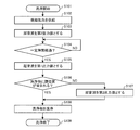
- FIG. 3 is a flowchart showing an example of the flow of the cleaning process by the cleaning apparatus 1 of FIG.
- the controller 14 is preferably a control device including a processor or the like.
- the cleaning apparatus 1 supplies fine bubbles into the cleaning liquid 2 by operating the fine bubble generator 17 after the start of cleaning (step S101) (step S102).
- the cleaning device 1 After supplying the fine bubbles into the cleaning liquid 2, the cleaning device 1 generates an ultrasonic wave having a second output value equal to or higher than the cavitation threshold from the ultrasonic generator 11 (step S103).
- the cleaning apparatus 1 further refines the fine bubbles by vapor cavitation generated by the ultrasonic wave having the second output value.
- the cleaning apparatus 1 determines whether or not a certain time has elapsed, for example, using a timer (not shown) provided in the controller 14 (step S104). ). When it is not determined that the predetermined time has elapsed (step S104: NO), the cleaning device 1 repeats the determination in step S104.
- the cleaning device 1 changes the ultrasonic output value of the ultrasonic wave generated from the ultrasonic generator 11 from the second output value to the first output value. (Step S105).
- the first output value is less than the cavitation threshold. That is, gaseous cavitation in which damage to the cleaning object 3 is suppressed is used in place of the vapor cavitation in which damage to the cleaning object 3 is large.
- the cleaning apparatus 1 determines whether or not the ultrasonic antinode position 82 that has become a standing wave is included in the range of the input cleaning object 3. A determination is made using the sound wave detector 13 (step S106).
- the cleaning object 3 When the cleaning object 3 is relatively small, there may be a situation where the ultrasonic anti-node position 82 which is a standing wave is not included in the range of the input cleaning object 3. In such a situation, since the abdominal position 82 where damage is likely to occur is not included, cleaning may be performed using vapor cavitation instead of gaseous cavitation that suppresses damage. Therefore, when it is determined that the ultrasonic anti-node position 82 that has become a standing wave is not included in the range of the thrown-in cleaning object 3 (step S106: NO), the cleaning device 1 is the second that is equal to or greater than the cavitation threshold. An ultrasonic wave having an output value is generated from the ultrasonic wave generator 11 (step S107). And the washing
- the cleaning device 1 when it is determined that the ultrasonic anti-node position 82 that has become a standing wave is included in the range of the thrown-in cleaning object 3 (step S106: YES), the cleaning device 1 outputs the first output that is less than the cavitation threshold value. An ultrasonic wave having a value is generated from the ultrasonic generator 11. And the washing
- the cleaning apparatus 1 whether the position where the cleaning object 3 is installed is the standing wave antinode 82 or the node position 83, and the cleaning object 3 is the standing wave antinode.
- the cleaning method for the cleaning object 3 differs depending on whether or not the dimensions are within the vicinity of 82 or the node position 83.
- cleaning apparatus 1 is divided according to the installation position and dimension of the washing
- the cleaning object 3 is installed in the vicinity of the antinode position 82 of the standing wave and the dimension of the cleaning object 3 fits in the vicinity of the antinode position 82 will be described.
- the antinode 82 and the node position 83 are formed every 1 ⁇ 4 of the wavelength of the ultrasonic wave 81. Therefore, the “near antinode position 82” in this example is a position that is 1/8 or less of the wavelength with the antinode position 82 of the standing wave as the center. That is, “the dimension of the cleaning object 3 that fits in the vicinity of the abdominal position 82” is a dimension that is 1 ⁇ 4 or less of the wavelength of the ultrasonic wave 81.
- FIG. 4A is a schematic diagram for explaining a cleaning method in the cleaning device 1 of FIG. 1 when the cleaning object 3a is installed at the antinode position 82 of the standing wave.
- the cleaning object 3a When the cleaning object 3a is cleaned at the antinode position 82 of the standing wave, the above-described vapor cavitation may occur at the position, and therefore the cleaning object 3a may be damaged by the shock wave of the vapor cavitation. There is sex. Therefore, in this cleaning method, the output of the ultrasonic wave 81 output from the ultrasonic generator 11 is set to an output that does not generate vapor cavitation.
- the antinode position 82 of the standing wave is first detected in advance.
- the detection of the abdominal position 82 is performed, for example, by moving the ultrasonic detector 13 in a direction parallel to the traveling direction of the ultrasonic wave 81 generated from the ultrasonic generator 11.
- the cleaning device 1 while the ultrasonic detector 13 is moved in a direction parallel to the traveling direction of the ultrasonic wave 81, the sound pressure of the ultrasonic wave 81 at each position is detected, and the standing wave based on the detected sound pressure is detected. Detects pressure fluctuation values.
- the ultrasonic detector 13 detects a position where the pressure fluctuation value is maximum from the detected values. This detected position becomes the antinode position 82 of the standing wave.
- the pressure fluctuation value at this time is defined as a first detection value.
- the controller 14 compares the ultrasonic output value when the first detection value is detected with a preset cavitation threshold in order to set the ultrasonic output value to an output value that does not cause vapor cavitation.
- the controller 14 controls the ultrasonic oscillator 12 so that the ultrasonic output value becomes the first output value that is equal to or less than the cavitation threshold value. Set to reduce ultrasound output.
- the controller 14 controls the ultrasonic oscillator 12 so that the ultrasonic output value is equal to or smaller than the cavitation threshold. In this case, it is desirable that the value be large so as not to exceed the cavitation threshold so that the cleaning power does not decrease.
- the cleaning apparatus 1 supplies the fine bubbles into the cleaning liquid 2 by operating the fine bubble generator 17 after the start of cleaning (step S101) (step S102). . Thereafter, the cleaning device 1 sets the ultrasonic output value from the ultrasonic generator 11 to the second output value (step S103).
- step S104 After a predetermined time has elapsed (step S104: Yes), the cleaning device 1 sets the ultrasonic output value from the ultrasonic generator 11 to the first output value (step S105). Thereafter, the cleaning object 3 is introduced, and the cleaning device 1 determines that the cleaning object 3 includes the antinode position 82 of the standing wave (step S106: Yes). And the washing
- the fine bubbles in the cleaning liquid 2 generated from the fine bubble generator 17 expand and contract on the surface of the cleaning object 3a due to the gaseous cavitation generated by the pressure fluctuation of the standing wave. Further, the fine bubbles move while being expanded and contracted, riding on the flow of the cleaning liquid 2 generated by the operation of the pump 15 or being pushed by the pressure at the antinode position 82 of the ultrasonic wave 81. By such movement of the fine bubbles, the dirt adhering to the surface of the cleaning object 3a is adsorbed and removed by the gas-liquid interface of the fine bubbles. Further, the expansion and contraction of the fine bubbles becomes a brushing effect on the surface of the cleaning object 3a, and the cleaning power can be improved.
- the cleaning object 3a when the cleaning object 3a is installed at the antinode position 82 of the standing wave, by setting the value of the ultrasonic output from the ultrasonic generator 11 as the first output value that does not generate vapor cavitation, The cleaning object 3 can be cleaned while suppressing damage to the cleaning object 3.
- the “near node position 83” in this example is a position that is 1/8 or less of the wavelength with the node position 83 of the standing wave as the center. That is, “the dimension of the cleaning object 3 that fits in the vicinity of the node position 83” is a dimension that is 1 ⁇ 4 or less of the wavelength of the ultrasonic wave 81.
- FIG. 4B is a schematic diagram for explaining a cleaning method in the cleaning apparatus 1 of FIG. 1 when the cleaning object 3a is installed at the node position 83 of the standing wave.
- the cleaning object 3a is cleaned at the standing wave node position 83, cavitation hardly occurs at the position, and the cleaning power is low as compared with the cleaning at the antinode position 82 of the standing wave. Therefore, in this cleaning method, cleaning is performed using fine bubbles captured at the node position 83 of the standing wave.
- the node position 83 of the standing wave is detected in advance.
- the detection of the node position 83 is performed, for example, by moving the ultrasonic detector 13 in a direction parallel to the traveling direction of the ultrasonic wave 81 generated from the ultrasonic generator 11, similarly to the detection of the abdominal position 82.
- the ultrasonic detector 13 detects the sound pressure of the ultrasonic wave 81 at each position by moving in a direction parallel to the traveling direction of the ultrasonic wave 81, and the pressure fluctuation value of the standing wave based on the detected sound pressure. Is detected.
- the ultrasonic detector 13 detects a position where the pressure fluctuation value is minimum from the detected values. This detected position becomes the node position 83 of the standing wave.
- the pressure fluctuation value at this time is set as the second detection value.
- the microbubbles generated by the microbubble generator 17 are crushed by using the shock wave generated by the vapor cavitation at the antinode position 82 of the standing wave, and further refined.
- the ultrasonic output value needs to be set to an output value at which vapor cavitation occurs at the antinode position 82 of the standing wave, that is, a value larger than the first output value. Moreover, in order to make fine bubbles more efficient by using shock waves generated by vapor cavitation, it is preferable to set the ultrasonic output value to a value equal to or higher than the cavitation threshold.
- the controller 14 compares the ultrasonic output value with the cavitation threshold value.
- the controller 14 sets the ultrasonic oscillator 12 so that the ultrasonic output value is higher than the first output value and becomes a second output value that is equal to or greater than the cavitation threshold. Control and set so as to increase the ultrasonic output from the ultrasonic generator 11.
- the controller 14 takes into consideration the cleaning object 3a, the state of dirt, and the like, and outputs the second output that is equal to or larger than the cavitation threshold and suitable for cleaning.
- the ultrasonic oscillator 12 is controlled to be a value.
- the cleaning apparatus 1 supplies the fine bubbles into the cleaning liquid 2 by operating the fine bubble generator 17 after the start of cleaning (step S101) (step S102). . Thereafter, the cleaning device 1 sets the ultrasonic output value from the ultrasonic generator 11 to the second output value (step S103).
- step S104 After a predetermined time has elapsed (step S104: Yes), the cleaning device 1 sets the ultrasonic output value from the ultrasonic generator 11 to the first output value (step S105). Thereafter, the cleaning object 3 is introduced, and the cleaning device 1 determines that the cleaning object 3 does not include the anti-node position 82 of the standing wave (step S106: No). Then, the cleaning apparatus 1 sets the ultrasonic output value from the ultrasonic generator 11 to the second output value (step S107), cleans the cleaning object 3 (step S108), and ends the cleaning (step S109). .
- the fine bubbles in the cleaning liquid 2 generated from the fine bubble generator 17 are further refined by the vapor cavitation generated at the antinode position 82 of the standing wave.
- the fine bubbles thus refined are moved by being pressed by the pressure at the abdominal position 82 and are captured at the node position 83.
- the fine bubbles captured at the node position 83 move along the surface of the cleaning object 3 a by the flow of the cleaning liquid 2 generated by the operation of the pump 15. Thereby, the dirt adhering to the surface of the cleaning object 3a is adsorbed and removed by the gas-liquid interface of the fine bubbles.
- the ultrasonic output from the ultrasonic generator 11 is set to the second output value at which vapor cavitation occurs at the abdominal position 82.
- the amount of fine bubbles acting on the cleaning object 3a can be increased to clean the cleaning object 3a.
- the cleaning object 3a can be cleaned by refining the bubbles by vapor cavitation to generate the fine bubbles and capturing the generated fine bubbles at the node position 83.
- the bubbles in the cleaning liquid 2 are constantly refined by vapor cavitation at the abdominal position 82 and trapped at the node position 83, so that the cleaning power decreases. Can be suppressed.
- the bubbles are continuously refined by vapor cavitation, and the fine bubbles are captured at the node positions 83 where the cleaning object 3a is present. Therefore, the amount of fine bubbles at the node positions 83 increases, and the cleaning object 3a is cleaned. The decrease in power can be suppressed.
- the dimension of the cleaning object 3 in this example is a dimension that is 1/4 or more of the wavelength of the ultrasonic wave 81.
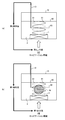
- FIG. 5 is a schematic diagram for explaining a cleaning method in the case where the installation position of the cleaning object 3b includes the anti-node position 82 and the node position 83 of the standing wave in the cleaning apparatus 1 of FIG.
- FIG. 5A shows a first state of the cleaning device 1 when the installation position of the cleaning object 3b includes a standing wave antinode position 82 and a node position 83.
- FIG. 5B shows a second state of the cleaning apparatus 1 when the installation position of the cleaning object 3b includes the antinode position 82 and the node position 83 of the standing wave.
- the following two methods can be considered.
- the cleaning apparatus 1 is set to the first state, and the ultrasonic generator 11 generates the cleaning object 3b before installing the cleaning object 3b in the cleaning tank 10.
- the second detection value is detected by moving the ultrasonic detector 13 in a direction parallel to the traveling direction of the ultrasonic wave 81.
- the controller 14 sets the output of the ultrasonic wave 81 generated from the ultrasonic wave generator 11 to the second output value.
- fine bubbles are generated in the cleaning liquid 2 by the fine bubble generator 17, and the pump 15 is operated to circulate the cleaning liquid 2.
- the fine bubbles in the cleaning liquid 2 are refined by vapor cavitation that occurs at the antinode position 82 of the standing wave.
- the fine bubbles are captured at the node position 83 of the standing wave.
- the ultrasonic wave 81 is output at the second output value for a predetermined time of 10 seconds or longer, preferably 1 minute or longer, and the state in which the cleaning liquid 2 is circulated by the pump 15 is maintained. This is because by setting the ultrasonic output to the second output, the fine bubbles in the cleaning liquid 2 are crushed and further refined, and the amount of bubbles is increased.
- the cleaning device 1 is set to the second state, and the first detection value is detected by moving the ultrasonic detector 13 in a direction parallel to the traveling direction of the ultrasonic wave 81.
- the output of the ultrasonic wave 81 generated from the ultrasonic generator 11 is set to the first output value.
- the cleaning object 3b is installed in the cleaning tank 10.
- the cleaning apparatus 1 supplies the fine bubbles into the cleaning liquid 2 by operating the fine bubble generator 17 after the start of cleaning (step S101) (step S102). . Thereafter, the cleaning device 1 sets the ultrasonic output value from the ultrasonic generator 11 to the second output value (step S103).
- step S104 After a predetermined time has elapsed (step S104: Yes), the cleaning device 1 sets the ultrasonic output value from the ultrasonic generator 11 to the first output value (step S105). Thereafter, the cleaning object 3 is introduced, and the cleaning device 1 determines that the cleaning object 3 includes the antinode position 82 of the standing wave (step S106: Yes). Then, the cleaning apparatus 1 cleans the cleaning object 3 while setting the ultrasonic output value from the ultrasonic generator 11 to the first output value (step S108).
- the controller 14 adjusts the ultrasonic oscillator 12 to sweep or modulate the frequency of the ultrasonic wave 81 in an arbitrary frequency range around the oscillation frequency, and continuously change the frequency of the ultrasonic wave 81.
- the antinode position 82 and the node position 83 of the standing wave are displaced along the traveling direction of the ultrasonic wave 81.
- the fine bubbles captured at the node position 83 move on the surface of the cleaning object 3b according to the displacement of the node position 83. Therefore, the dirt adhering to the surface of the cleaning object 3b is adsorbed and removed by the gas-liquid interface of the fine bubbles.
- the frequency range of the ultrasonic wave 81 that changes at this time is determined according to the distance between the abdominal position 82 and the node position 83.
- the cleaning apparatus 1 is set in the second state, and is generated from the ultrasonic generator 11 before the cleaning object 3b is installed in the cleaning tank 10.
- the first detection value is detected by moving the ultrasonic detector 13 in a direction parallel to the traveling direction of the ultrasonic wave 81.
- the controller 14 sets the output of the ultrasonic wave 81 generated from the ultrasonic wave generator 11 to the first output value.
- fine bubbles are generated in the cleaning liquid 2 by the fine bubble generator 17 and the pump 15 is operated to circulate the cleaning liquid 2, and then the cleaning product 3 b is placed in the cleaning tank 10 while maintaining this state. . Thereby, the fine bubbles are captured at the node position 83 of the standing wave.
- the cleaning apparatus 1 supplies the fine bubbles into the cleaning liquid 2 by operating the fine bubble generator 17 after the start of cleaning (step S101) (step S102). .
- the cleaning apparatus 1 omits steps S103 and S104, and sets the ultrasonic output value from the ultrasonic generator 11 to the first output value (step S105).
- the cleaning object 3 is introduced, and the cleaning device 1 determines that the cleaning object 3 includes the antinode position 82 of the standing wave (step S106).
- the cleaning apparatus 1 cleans the cleaning object 3 while setting the ultrasonic output value from the ultrasonic generator 11 to the first output value (step S108).
- the controller 14 adjusts the ultrasonic oscillator 12 to sweep or modulate the frequency of the ultrasonic wave 81 in an arbitrary frequency range around the oscillation frequency, and continuously change the frequency of the ultrasonic wave 81.
- the antinode position 82 and the node position 83 of the standing wave are displaced along the traveling direction of the ultrasonic wave 81.
- the fine bubbles captured at the node position 83 move on the surface of the cleaning object 3b according to the displacement of the node position 83. Therefore, the dirt adhering to the surface of the cleaning object 3b is adsorbed and removed by the gas-liquid interface of the fine bubbles.
- the frequency range of the ultrasonic wave 81 that changes at this time is determined according to the distance between the antinode position 82 and the node position 83, as in the first method.
- the node position 83 exceeds the distance. It is preferable to change the frequency of the ultrasonic wave 81 so as to change. Thereby, the node position 83 can be moved over the entire surface of the cleaning object 3b, and the dirt adhering to the entire surface of the cleaning object 3b can be removed.
- the distance between the antinode position 82 and the node position 83, the frequency range in which the ultrasonic wave 81 is changed, and the like are preferably investigated in advance by experiments or the like, as in the first method.
- the ultrasonic output from the ultrasonic generator 11 is output. Is the first output value, and the ultrasonic wave frequency is adjusted so that the node position 83 of the standing wave moves on the entire surface of the cleaning object 3b, thereby suppressing damage to the cleaning object 3b and uniforming the entire cleaning object 3a. Can be washed. Specifically, the bubbles are refined by vapor cavitation to generate fine bubbles, and then changed to gaseous cavitation.
- cleaning is performed using the generated fine bubbles and gaseous cavitation, and the frequency of the ultrasonic wave 81 is continuously changed during cleaning, thereby suppressing damage to the cleaning object 3b and the entire cleaning object 3b. It can be washed uniformly.
- the frequency sweep or modulation of the ultrasonic wave 81 is performed to move the node position 83 of the standing wave with respect to the cleaning object 3b.
- the node position 83 is moved.
- the method is not limited to this example.
- the relative position with respect to the node position 83 of the standing wave may be moved by moving the cleaning object 3 b in a direction parallel to the traveling direction of the ultrasonic wave 81. Thereby, when washing
- the distance to which the cleaning object 3b is moved is also determined according to the distance between the abdominal position 82 and the node position 83. For example, the cleaning object 3b is changed so that the node position 83 changes more than the distance. Is preferably moved.
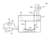
- FIG. 6 is a schematic diagram showing an example of the configuration of a verification device 90 that verifies the state of fine bubbles.
- the ultrasonic output is set to the second output value
- the fine bubbles are crushed and captured at the node position 83 of the standing wave
- the ultrasonic output is set to the first output value. Is maintained.
- the fine bubbles in the cleaning liquid 2 in this state were observed, and the distribution of the fine bubbles was verified.
- an ultrasonic generator 93 is installed at the bottom of the cleaning tank 91 filled with the cleaning liquid 92. Then, the cleaning liquid 92 in the cleaning tank 91 is circulated using a pump 94 provided in a liquid pipe 96 connected to the cleaning tank 91, and the gas supplied through the intake pipe 97 in the fine bubble generator 95. Are used to generate fine bubbles in the cleaning liquid 92.
- an ultrasonic wave 81 whose ultrasonic output is set to the second output is irradiated in the liquid surface direction of the cleaning liquid 92.
- a standing wave is formed in the cleaning liquid 92.
- the fine bubbles generated in the cleaning liquid 92 are crushed and refined at the antinode position of the standing wave.
- the cleaning liquid 92 at the position where the fine bubbles are crushed is sucked up into the transparent slit 100 connected via the tube 102 using the pump 101.
- the cleaning liquid 92 sucked into the slit 100 was photographed from the side surface of the slit 100, and the distribution of fine bubbles was observed.
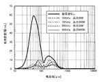
- FIG. 7 is a graph showing the distribution of fine bubbles observed using the verification device 90 of FIG.
- the horizontal axis indicates the bubble diameter of the fine bubbles contained in the cleaning liquid 92 sucked up by the slit 100.
- the vertical axis indicates the bubble density of fine bubbles in the cleaning liquid 92 sucked up by the slit 100.
- the bubble density that is, the number of bubbles is decreased by irradiating the ultrasonic wave 81, but this is because fine bubbles are trapped at the node position of the standing wave and sucked into the slit 100. This is because the number of bubbles in the cleaning liquid 92 is reduced.
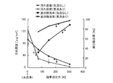
- FIG. 8 is a schematic diagram showing a first cleaning result when the cleaning object 3 is cleaned using the cleaning apparatus 1 of FIG.
- FIG. 9 is a schematic view showing a second cleaning result when the cleaning object 3 is cleaned using the cleaning apparatus 1 of FIG.
- FIG. 8 shows the cleaning result when the ultrasonic frequency is 40 kHz.
- FIG. 9 shows the cleaning result when the ultrasonic frequency is 100 kHz.
- an acrylic plate to which triolein was attached was used as a cleaning sample, and the dirt density and oil removal rate of the cleaning sample were evaluated using ultrasonic output as a parameter for the presence or absence of bubbles.
- the washing time was 10 minutes. From the results shown in FIGS. 8 and 9, it can be confirmed that the use of the ultrasonic wave 81 and the bubbles together improves the cleaning power as compared with the case where only the ultrasonic wave 81 is used. In particular, it can be confirmed that the higher the frequency and the lower the output, the higher the synergistic effect of the combined use of the ultrasonic wave 81 and the bubbles.
- an aluminum foil having a thickness of 11 ⁇ m was evaluated as a sample.
- An aluminum foil was installed at the same position as the cleaning position in the cleaning evaluation described above, and the ultrasonic wave 18 was irradiated for 10 minutes.
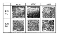
- FIG. 10 is a schematic diagram showing a damage evaluation result by the ultrasonic wave 81 when the sample is irradiated with the ultrasonic wave 81 using the cleaning apparatus 1 of FIG.
- the broken line in the figure indicates the antinode position 82 of the standing wave sound pressure of the ultrasonic wave 81 generated in the cleaning tank 10.
- the oil removal rate was almost equal to about 90%, but the latter could not visually confirm damage to the aluminum foil. Therefore, it can be confirmed that by using bubbles, the cleaning power can be improved while reducing the ultrasonic output and suppressing the damage.
- the cleaning apparatus 1 according to Embodiment 1 can be applied to, for example, cleaning of a separation membrane used in a water treatment system called a membrane separation bioreactor (MBR).
- MLR membrane separation bioreactor
- Membrane separation bioreactor is one of water treatment methods such as waterworks, sewerage, industrial water or various wastewaters. After biological treatment by activated sludge method etc., pollutants such as organic substances using separation membrane Is removed and water treatment is performed.
- pollutants such as organic substances using separation membrane Is removed and water treatment is performed.
- the separation membrane is continuously used, contaminants adhere to the surface, inside, and pores of the separation membrane, resulting in clogging of the separation membrane, and the filtration performance gradually decreases.
- the pressure required to filter the water to be treated increases, so the amount of membrane filtration water per unit time and unit membrane area decreases, and the performance of the filtration membrane decreases. End up. Therefore, in order to maintain the performance of the filtration membrane, it is necessary to periodically wash the separation membrane.
- a method of cleaning the separation membrane there is a method of removing contaminants adhering to the surface of the filtration membrane by immersing the separation membrane in cleaning water containing an oxidizing agent such as ozone or sodium hypochlorite.
- cleaning water containing an oxidizing agent such as ozone or sodium hypochlorite.
- filtered water, clarified water, or cleaning water containing an oxidizing agent such as ozone or sodium hypochlorite is filtered from the filtered water side opposite to the filtration direction of the separation membrane.
- the cleaning device 1 according to the first embodiment can be applied when the separation membrane is immersed in cleaning water for cleaning. That is, the cleaning object 3 shown in FIG. 1 becomes a separation membrane, and the separation membrane can be cleaned by using cleaning water 2 containing cleaning water containing an oxidizing agent such as ozone or sodium hypochlorite.
- an oxidizing agent such as ozone or sodium hypochlorite.
- the processing capacity of the entire water treatment system is equivalent to the amount of removal of the separation membrane for washing. descend. Therefore, shortening of the washing time is desired in order to suppress a decrease in the treatment capacity of the water treatment system in a short time. Therefore, by applying the method of immersing the separation membrane in the cleaning water using the cleaning device 1 according to the first embodiment, the cleaning time can be shortened and the processing capacity of the water treatment system can be reduced quickly. Can be suppressed.
- the size of the separation membrane of the water treatment system is usually 2 m or more, and it takes labor to remove the separation membrane from the water treatment system. Therefore, it is desired to clean the separation membrane in-line rather than removing the separation membrane from the water treatment system. That is, it is desired to wash the separation membrane while it is installed in the water treatment system.
- the cleaning apparatus 1 according to Embodiment 1 when the separation membrane is removed from the MBR water treatment system for cleaning, not only the shortening of the cleaning time is shortened, but the separation membrane is removed from the MBR water treatment system. Without washing, it is possible to perform in-line washing with the separation membrane installed in the biological treatment tank.
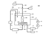
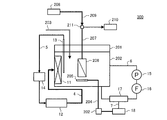
- FIG. 11 is a schematic diagram illustrating an example of the configuration of the cleaning apparatus 200 according to Example 1 of the first embodiment.
- the separation membrane 206 in which the activated sludge 202 is placed in the cleaning device 200, the separation membrane 206, the ultrasonic generator 11, the ultrasonic detector 13, the aeration device 205, and the like. Is installed.
- the ultrasonic generator 11 is installed on the bottom surface of the biological treatment tank 201 and is connected to the ultrasonic oscillator 12 through the ultrasonic output line 4.
- the ultrasonic detector 13 is connected to the controller 14 and the ultrasonic oscillator 12 through the control line 5.
- the air diffuser 205 generates air bubbles to diffuse the separation membrane 206, and is connected to the gas supply source 18 through the gas introduction pipe 204.
- a treated water introduction pipe 203 is connected to the biological treatment tank 201.
- the biological treatment tank 201 is connected to the pump 15, the filter 16, and the fine bubble generator 17 through the liquid pipe 6.
- the fine bubble generator 17 is connected to the gas supply source 18 through the intake pipe 7.
- the separation membrane 206 is connected to the treated water drain 210 through the permeate transfer pipe 207 provided with the flow path switch 211.
- the flow path switch 211 is connected to the cleaning water injection device 208 through the cleaning water injection pipe 209.
- treated water is introduced into the biological treatment tank 201 through the treated water introduction pipe 203, and organic matter is decomposed by microorganisms in the activated sludge 202.
- the activated sludge 202 is filtered by the separation membrane 206 and transferred to the treated water drain 210 by the permeate transfer pipe 207.
- the air diffuser 205 performs bubbling with the gas supplied from the gas supply source 18 through the gas introduction pipe 204 in order to make it difficult to block the separation membrane 206.
- the cleaning apparatus 200 operates the pump 15 to introduce the fine bubbles generated by the fine bubble generator 17 into the activated sludge 202.
- the cleaning process at this time is as shown in the flowchart of FIG.
- the ultrasonic generator 11 outputs the second output
- the separation membrane 206 is protected by the gas supplied from the air diffuser 205
- the separation membrane 206 is not damaged.
- the gas supplied from the air diffuser 205 is refined by the ultrasonic waves 81 irradiated from the ultrasonic generator 11. Thereby, the number of fine bubbles near the separation membrane 206 is increased, and the cleaning power is improved.
- the flow path switch 211 is opened to the cleaning water injection device 208 side, so that the cleaning water can be injected into the separation membrane 206 and the separation membrane 206 can be backwashed. Therefore, the combined use with the cleaning method according to Embodiment 1 improves the cleaning power of the separation membrane 206.
- the cleaning power is further improved by using cleaning water containing an oxidizing agent such as ozone or sodium hypochlorite as the cleaning water.
- Such reverse cleaning of the separation membrane 206 can be performed at an arbitrary timing during the operation by the cleaning method according to the first embodiment.
- FIG. 12 is a schematic diagram showing another example of the configuration of the cleaning apparatus 200 according to Example 1 of the first embodiment.
- the ultrasonic generator 11 is installed on the bottom surface of the biological treatment tank 201.
- it can be installed on the side surface of the biological treatment tank 201 as shown in FIG.
- the gas introduced into the fine bubbles and the diffuser 205 is not limited to air, and an oxidizing gas such as ozone can also be used.
- FIG. 13 is a schematic diagram illustrating an example of the configuration of the cleaning apparatus 300 according to Example 2 of the first embodiment.
- the cleaning device 300 according to the second embodiment has a configuration in which a gas amount controller 212 is added to the gas introduction pipe 204 with respect to the configuration of the cleaning device 200 according to the first embodiment illustrated in FIG. 12. is there.
- the operation of the cleaning apparatus 300 according to the second embodiment is roughly the same as that of the first embodiment, but is different in that the amount of gas supplied to the diffuser 205 is controlled by the gas amount controller 212.
- the gas amount controller 212 increases the amount of gas to the diffuser 205 so that the separation membrane 206 is not damaged. Thereby, a gas layer is formed in the vicinity of the separation membrane 206 to protect the separation membrane 206.
- the ultrasonic wave 81 has almost zero transmittance from the liquid to the air. Therefore, when there is a gas layer in the vicinity of the separation membrane 206, the ultrasonic wave 81 does not reach the separation membrane 206. At this time, part of the gas layer formed in the vicinity of the separation membrane 206 is exfoliated and refined by vapor cavitation, and the number of fine bubbles in the vicinity of the separation membrane 206 increases. This improves the cleaning power.
- the cleaning power is improved.
- the separation membrane 206 can be backwashed. Such reverse cleaning of the separation membrane 206 can be performed at an arbitrary timing during the operation by the cleaning method according to the first embodiment.
- the ultrasonic generator 11 is installed on the side surface of the biological treatment tank 201.
- the ultrasonic generator 11 is replaced with the biological treatment tank as in the example shown in FIG. It can also be installed on the bottom surface of 201.
- the gas introduced into the fine bubbles and the diffuser 205 is not limited to air, and for example, an oxidizing gas such as ozone may be used.
- FIG. 14 is a schematic diagram illustrating an example of the configuration of the cleaning apparatus 400 according to Example 3 of the first embodiment.
- the cleaning device 400 according to the third embodiment has a configuration in which a gas introduction pipe 213 and a flow path switching unit 214 are added to the configuration of the cleaning device 300 according to the second embodiment illustrated in FIG. 13. is there.
- the flow path switching unit 214 is provided between the gas amount controller 212 of the gas introduction pipe 204 and the air diffuser 205.
- the flow path switch 214 is connected to the flow path switch 211 of the permeate transfer pipe 207 through the gas introduction pipe 213.
- the operation of the cleaning apparatus 400 according to the third embodiment is roughly the same as that of the first and second embodiments, but is different in the points described below.
- the cleaning device 400 switches between the flow path switching device 211 and the flow path switching device 214, so that the opposite side of the separation membrane 206, that is, the processing.
- a gas is introduced into the separation membrane 206 from the water outlet side, and the gas is introduced into the activated sludge 202.
- a gas layer is formed in the vicinity of the separation membrane 206, and the separation membrane 206 can be protected so that the separation membrane 206 is not damaged by the ultrasonic wave 81.
- the ultrasonic wave 81 has almost zero transmittance from the liquid to the air. Therefore, when there is a gas layer in the vicinity of the separation membrane 206, the ultrasonic wave 81 does not reach the separation membrane 206. At this time, part of the gas layer formed in the vicinity of the separation membrane 206 is exfoliated and refined by vapor cavitation, and the number of fine bubbles in the vicinity of the separation membrane 206 increases. This improves the cleaning power.
- the cleaning device 400 diffuses the flow path switch 214 so that the separation membrane 206 and the cleaning water injection pipe 209 are electrically connected.
- the separation membrane 206 is washed by switching to the apparatus 205 side.
- the gaseous cavitation hardly acts on the surface of the separation membrane 206, and the cleaning power is reduced. Therefore, when the first ultrasonic output is output from the ultrasonic generator 11, the amount of gas to the diffuser 205 is decreased. Thereby, gaseous cavitation acts on the surface of the separation membrane 206 and the cleaning power is improved. Furthermore, since the gas from the air diffuser 205 is refined and the number of fine bubbles increases, the cleaning power is improved.
- the ultrasonic generator 11 is installed on the side surface of the biological treatment tank 201.
- the ultrasonic generator 11 is placed on the bottom surface of the biological treatment tank 201 as in the example shown in FIG. 11. It can also be installed.
- the gas introduced into the fine bubbles and the diffuser 205 is not limited to air, and for example, an oxidizing gas such as ozone may be used.
- the cleaning object 3 is cleaned by installing the cleaning object 3 at one of the antinode position 82 and the node position 83 in the standing wave formed in the cleaning tank 10.
- the output of the ultrasonic wave 81 generated from the ultrasonic generator 11 is adjusted based on the positional relationship between the cleaning object 3 and the antinode position 82 and the node position 83 of the standing wave.
- the cleaning object 3 can be cleaned while suppressing the occurrence of damage to the cleaning object 3.
- the frequency of the ultrasonic wave 81 is set so that the node position 83 moves on the entire surface of the cleaning object 3. Sweep or cleaning object 3 is moved. Thereby, the cleaning object 3 can be uniformly cleaned while suppressing the occurrence of damage to the cleaning object 3.
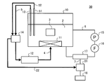
- FIG. 15 is a schematic diagram showing an example of the configuration of the cleaning apparatus 20 according to Embodiment 2 of the present invention.
- This cleaning device 20 is different from the above-described first embodiment in that an intake controller 21 is provided between the fine bubble generator 17 and the gas supply source 18.
- an intake controller 21 is provided between the fine bubble generator 17 and the gas supply source 18.
- the cleaning apparatus 20 includes a cleaning tank 10, an ultrasonic generator 11, an ultrasonic oscillator 12, an ultrasonic detector 13, a controller 14, a pump 15, a filter 16, a fine bubble generator 17, and a gas.
- a supply source 18 and an intake air controller 21 are included.
- the intake controller 21 is provided between the fine bubble generator 17 and the gas supply source 18, and is connected to the fine bubble generator 17 and the gas supply source 18 via the intake pipe 7.
- the intake controller 21 adjusts at least one of the amount of gas supplied from the gas supply source 18 to the fine bubble generator 17 and the intake timing based on the control of the controller 14 connected by the control line 22, and the adjusted gas Is supplied to the fine bubble generator 17.
- the controller 14 controls the ultrasonic oscillator 12 in the same manner as in the first embodiment based on the information about the ultrasonic wave 81 such as the energy, sound pressure, and frequency of the ultrasonic wave 81 detected by the ultrasonic wave detector 13.
- the intake controller 21 is controlled.
- the cleaning device 20 forms a standing wave in the cleaning liquid 2 in the cleaning tank 10 by irradiating the ultrasonic wave 81 from the ultrasonic generator 11.
- standing wave energy, sound pressure, and the like at the position where the cleaning object 3 is installed are detected by the ultrasonic detector 13.
- the controller 14 controls the ultrasonic oscillator 12 to adjust the output of the ultrasonic wave 81 generated from the ultrasonic wave generator 11.
- the controller 14 controls the intake controller 21 based on the detection result of the ultrasonic detector 13, and the amount of gas supplied from the gas supply source 18 to the fine bubble generator 17 and the intake air are controlled. Control at least one of the timings. That is, in the flowchart shown in FIG. 3, the cleaning device 20 determines the amount of gas supplied from the gas supply source 18 to the fine bubble generator 17 and the intake timing in one or both of step S103 and step S108. Control at least one.
- the amount of gas intake is increased in order to increase the number of fine bubbles.
- the gas is intermittently sucked, and intermittent suction of the maximum number of fine bubbles effective for cleaning is maximized. Adjust to timing. That is, in the above example, in the flowchart shown in FIG. 3, the cleaning device 20 increases the amount of gas intake in step S104 and controls the timing of intermittent gas intake in step S108. Thereby, the quantity of fine bubbles generated in the cleaning liquid 2 in the cleaning tank 10, the bubble diameter, and the like can be controlled.
- the ultrasonic detector 13 detects the first detection value indicating the antinode position 82 where the pressure fluctuation of the standing wave is maximum at the cleaning position of the cleaning object 3.
- the ultrasonic generator 11 outputs the ultrasonic wave 81 in which the ultrasonic output is set to the first output value via the ultrasonic oscillator 12. Therefore, the fine bubbles on the surface of the cleaning object 3 are expanded and contracted by the gaseous cavitation generated by the pressure fluctuation of the standing wave, and the dirt adhering to the surface of the cleaning object 3 is adsorbed at the gas-liquid interface and removed.
- the cleaning object 3 when the cleaning object 3 is cleaned at the antinode position 82 of the standing wave, the amount of fine bubbles in the cleaning liquid 2 does not become an amount that inhibits the generation of gaseous cavitation.
- the amount of fine bubbles generated by the bubble generator 17 is controlled. That is, in step S108 in the flowchart shown in FIG. 3, the cleaning device 20 controls the amount of fine bubbles.
- the ultrasonic detector 13 detects the second detection value indicating the node position 83 at which the pressure fluctuation of the standing wave is minimum at the cleaning position of the cleaning object 3.
- the ultrasonic generator 11 outputs the ultrasonic wave 81 in which the ultrasonic output is set to the second output value via the ultrasonic oscillator 12. Therefore, the fine bubbles in the cleaning liquid 2 are further crushed and refined by the vapor cavitation generated at the antinode position 82 of the standing wave.
- the fine bubbles thus refined are moved by being pressed by the pressure at the abdominal position 82 and are captured at the node position 83. Thereby, the dirt adhering to the surface of the cleaning object 3 installed at the node position 83 is adsorbed to the gas-liquid interface and removed.
- the cleaning object 3 when the cleaning object 3 is cleaned at the node position 83 of the standing wave, the amount of fine bubbles in the cleaning liquid 2 does not become an amount that inhibits the generation of vapor cavitation.
- the amount of fine bubbles generated by the bubble generator 17 is controlled. That is, in step S103 in the flowchart shown in FIG. 3, the cleaning device 20 controls the amount of fine bubbles. As a result, attenuation of ultrasonic energy caused by excessive fine bubbles can be prevented, and vapor cavitation can be efficiently generated. Therefore, the reduction in the number of fine bubbles to be crushed is suppressed, and the cleaning power for the cleaning object 3 is improved. Can be improved.
- the cleaning object 3 is cleaned by using the first method or the second method described in the first embodiment. Can do.
- the amount of the fine bubbles that inhibit the ultrasonic energy of the standing wave differs depending on the use environment such as the type and temperature of the cleaning liquid 2, the ultrasonic frequency, and the type of gas contained in the fine bubbles.
- various parameters such as the intake air amount, intermittent intake air, and the like suitable for the use environment are investigated in advance through experiments or the like.
- the intake air controller 21 adjusts the amount of fine bubbles in the cleaning liquid 2. Therefore, it is possible to prevent the occurrence of cavitation from being inhibited and improve the cleaning power for the cleaning object 3.
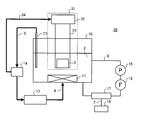
- FIG. 16 is a schematic diagram illustrating an example of the configuration of the cleaning device 30 according to the third embodiment of the present invention.
- This cleaning device 30 is different from the first embodiment described above in that it includes a cleaning object control unit 31 that controls the position of the cleaning object 3 when cleaning the cleaning object 3.
- the same parts as those in the first and second embodiments are denoted by the same reference numerals, and detailed description thereof is omitted.
- the cleaning apparatus 30 includes a cleaning tank 10, an ultrasonic generator 11, an ultrasonic oscillator 12, an ultrasonic detector 13, a controller 14, a pump 15, a filter 16, a fine bubble generator 17, and a gas.
- a supply source 18 and a cleaning object control unit 31 are included.
- the cleaning object control unit 31 includes a position controller 32 and a holder 33.
- the holder 33 is provided to hold the position of the cleaning object 3 in the cleaning liquid 2.
- the holder 33 is driven by the control of the position controller 32 and moves in a direction parallel to the traveling direction of the ultrasonic wave 81 emitted from the ultrasonic wave generator 11.
- the position controller 32 is connected to the controller 14 via the control line 34, and controls the position of the holder 33 based on the control of the controller 14.
- the controller 14 controls the ultrasonic oscillator 12 in the same manner as in the first embodiment based on the information about the ultrasonic wave 81 such as the energy, sound pressure, and frequency of the ultrasonic wave 81 detected by the ultrasonic wave detector 13.
- the position controller 32 is controlled.
- the cleaning device 30 forms a standing wave in the cleaning liquid 2 in the cleaning tank 10 by irradiating the ultrasonic wave 81 from the ultrasonic generator 11.
- standing wave energy, sound pressure, and the like at the position where the cleaning object 3 is installed are detected by the ultrasonic detector 13.
- the controller 14 controls the ultrasonic oscillator 12 to adjust the output of the ultrasonic wave 81 generated from the ultrasonic wave generator 11.
- the controller 14 controls the position controller 32 and drives the holder 33 to control the position of the cleaning object 3. That is, in step S108 in the flowchart shown in FIG. 3, the cleaning device 30 drives the holder 33 to control the position of the cleaning object 3.
- One cleaning method is a method for cleaning the cleaning object 3 by using the ultrasonic output as the first output value and using the expansion and contraction of the fine bubbles by the gaseous cavitation.
- the other cleaning method is a method in which the cleaning object 3 is cleaned by adsorbing dirt to the gas-liquid interface of the fine bubbles captured at the node position 83 of the standing wave using the ultrasonic output as the second output value.
- the ultrasonic output is used as the first output value, and cleaning is performed using expansion and contraction of fine bubbles by gaseous cavitation.
- the ultrasonic output is set as the second output value, and the gas-liquid interface of the fine bubbles is contaminated. Adsorb and wash.
- two cleaning methods can be selected according to the characteristics of the cleaning object 3 and the characteristics of dirt attached to the cleaning object 3.
- the controller 14 controls the position controller 32 of the washing
- the position controller 32 drives the holder 33 based on the control of the controller 14 so that the cleaning object 3 is located at the antinode position 82.
- the controller 14 controls the ultrasonic oscillator 12 so that the output of the ultrasonic wave 81 irradiated from the ultrasonic generator 11 becomes the first output value.
- the ultrasonic wave 81 having the first output value is irradiated from the ultrasonic generator 11, and the fine bubbles in the cleaning liquid 2 expand the surface of the cleaning object 3 a by the gaseous cavitation generated by the pressure fluctuation of the standing wave. Move while contracting. Then, due to the movement of the fine bubbles, the dirt adhering to the surface of the cleaning object 3a is adsorbed and removed by the gas-liquid interface of the fine bubbles.
- the controller 14 controls the position controller 32 of the cleaning object control unit 31 based on the position information indicating the node position 83 detected in advance. Based on the control of the controller 14, the position controller 32 drives the holder 33 so that the cleaning object 3 is positioned at the node position 83.
- the controller 14 controls the ultrasonic oscillator 12 so that the output of the ultrasonic wave 81 irradiated from the ultrasonic generator 11 becomes the second output value. Accordingly, the ultrasonic wave 81 having the second output value is irradiated from the ultrasonic generator 11, and the fine bubbles in the cleaning liquid 2 are further refined by the vapor cavitation generated at the abdominal position 82. Then, the refined fine bubbles are captured at the node position 83, and the dirt adhering to the surface of the cleaning object 3a is adsorbed and removed by the gas-liquid interface of the fine bubbles.
- the cleaning object 3 can be cleaned when the position of the cleaning object 3 includes the abdomen position 82 and the node position 83.
- the cleaning object 3 can be moved in a direction parallel to the traveling direction of the ultrasonic wave 81 by holding and driving the cleaning object 3 in the holder 33. Therefore, the cleaning object 3 can be cleaned without using the first method or the second method described in the first embodiment.
- the output of the ultrasonic wave 81 is set to the first output value or the second output value in accordance with the characteristic of the cleaning object 3 or the characteristic of dirt adhering to the cleaning object 3, and the cleaning object 3 is moved via the holder 33. By moving, the surface of the cleaning object 3 can be cleaned uniformly.
- the energy of the ultrasonic wave 81 has a distribution in the lateral direction, that is, the direction perpendicular to the traveling direction of the ultrasonic wave 81. Therefore, the surface of the cleaning object 3 is uniformly cleaned by moving the cleaning object 3 in the lateral direction, that is, in a direction including at least one of the direction parallel to the traveling direction of the ultrasonic wave 81 and the direction perpendicular thereto. can do.
- the moving distance of the cleaning object 3 at this time is preferably longer than the distance between the position where the first detection value is detected and the position where the second detection value is detected. This is for moving the abdominal position 82 or the node position 83 over the entire surface of the cleaning object 3. This moving distance is preferably investigated in advance by experiments or the like.
- the ultrasonic detector 13 is moved in a direction parallel to the traveling direction of the ultrasonic wave 81, and the detection position of the first detection value and the detection position of the second detection value are measured. Then, the movement of the holder 33 may be automatically controlled based on the measurement result.
- the cleaning object control unit 31 is provided, and the cleaning object 3 held by the retainer 33 is moved to perform cleaning.
- an appropriate cleaning method can be selected according to the output value of the ultrasonic wave 81 or the state of dirt adhering to the cleaning object 3.
- the cleaning object 3 can be moved in a direction parallel to the traveling direction of the ultrasonic wave 81, the entire surface of the cleaning object 3 can be obtained even when the position of the cleaning object 3 includes the abdominal position 82 and the node position 83. Can be washed uniformly.
- the cleaning object 3 when the cleaning object 3 is moved in a direction including at least one of a direction parallel to the traveling direction of the ultrasonic wave 81 and a direction perpendicular thereto, a water flow is generated on the surface of the cleaning object 3.
- the liquid replacement property of the cleaning liquid 2 in the cleaning tank 10 is improved, and the cleaning object 3 can be efficiently cleaned.
- the antinode position 82 and the node position 83 of the standing wave change. Therefore, for example, by periodically moving the ultrasonic detector 13 and monitoring the state of the standing wave formed in the cleaning tank 10, the detection position of the first detection value and the second detection value can be changed. Accordingly, the cleaning object 3 can be moved. Thereby, the cleaning product 3 can be efficiently cleaned, and for example, the yield of the cleaning product 3 can be improved.
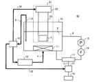
- FIG. 17 is a schematic diagram showing an example of the configuration of the cleaning device 40 according to Embodiment 4 of the present invention.
- This cleaning device 40 is a combination of the above-described second and third embodiments.
- the same parts as those in the first to third embodiments are denoted by the same reference numerals, and detailed description thereof is omitted.
- the cleaning apparatus 40 includes a cleaning tank 10, an ultrasonic generator 11, an ultrasonic oscillator 12, an ultrasonic detector 13, a controller 14, a pump 15, a filter 16, a fine bubble generator 17, a gas.
- a supply source 18, an intake air controller 21, and a cleaning object control unit 31 are included.
- the cleaning device 40 irradiates the ultrasonic wave 81 from the ultrasonic generator 11 to form a standing wave in the cleaning liquid 2 in the cleaning tank 10.
- standing wave energy, sound pressure, and the like at the position where the cleaning object 3 is installed are detected by the ultrasonic detector 13.
- the controller 14 controls the ultrasonic oscillator 12 to adjust the output of the ultrasonic wave 81 generated from the ultrasonic wave generator 11.
- the intake controller 21 is controlled by the controller 14 based on the detection result of the ultrasonic detector 13, as in the second embodiment. For example, when the detection value detected by the ultrasonic detector 13 is larger than the cavitation threshold, the amount of gas intake is increased in order to increase the number of fine bubbles. Further, for example, when the detection value detected by the ultrasonic detector 13 is smaller than the cavitation threshold value, the gas is intermittently sucked, and intermittent suction of the maximum number of fine bubbles effective for cleaning is maximized. Adjust to timing. That is, in the above example, in the flowchart shown in FIG. 3, the cleaning device 40 uses the gas supply source 18 to supply the fine bubble generator 17 in one or both of step S103 and step S108. Control at least one of quantity and intake timing. Thereby, the amount of fine bubbles generated in the cleaning liquid 2, the bubble diameter, and the like can be controlled.
- the cleaning object control unit 31 is controlled based on the detection result of the ultrasonic detector 13, as in the third embodiment. That is, in step S108 in the flowchart shown in FIG. 3, the cleaning device 40 drives the retainer 33 to control the position of the cleaning object 3.
- a desired cleaning method among a method of cleaning the cleaning object 3 using expansion and contraction of fine bubbles by gas cavitation and a method of cleaning the cleaning object 3 by adsorbing dirt to the gas-liquid interface of the fine bubbles Can be selected. That is, in the cleaning apparatus 40, the amount of fine bubbles, the bubble diameter, and the like can be optimized according to the selected cleaning method.
- the amount of fine bubbles that inhibit the ultrasonic energy of the standing wave is determined based on the type and temperature of the cleaning liquid 2, the ultrasonic frequency, the type of gas contained in the fine bubbles, and the like. It depends on the environment. For this reason, it is preferable that various parameters such as the intake air amount, intermittent intake air, and the like suitable for the use environment are investigated in advance through experiments or the like.
- the amount of fine bubbles in the cleaning liquid 2 is adjusted by the intake air controller 21, so that the occurrence of cavitation is prevented and the cleaning is performed.
- the detergency with respect to the thing 3 can be improved.
- the cleaning object 3 is moved by the holder 33 of the cleaning object control unit 31 to perform cleaning. This makes it possible to select an appropriate cleaning method according to the output value of the ultrasonic wave 81 or the state of dirt adhering to the cleaning object 3, and to efficiently and uniformly clean the cleaning object 3.
- FIG. 18 is a schematic diagram illustrating an example of the configuration of the cleaning device 50 according to Embodiment 5 of the present invention.
- This cleaning device 50 is different from the above-described second embodiment in that a bubble detector 51 is provided in the cleaning tank 10.
- the same parts as those in the first to fourth embodiments are denoted by the same reference numerals, and detailed description thereof is omitted.
- the cleaning device 50 includes a cleaning tank 10, an ultrasonic generator 11, an ultrasonic oscillator 12, an ultrasonic detector 13, a controller 14, a pump 15, a filter 16, a fine bubble generator 17, and a gas.
- a supply source 18, an intake air controller 21 and a bubble detector 51 are included.
- the bubble detector 51 is installed in the cleaning tank 10 and connected to the controller 14 via the control line 52.
- the bubble detector 51 detects the characteristics of the fine bubbles such as the amount of fine bubbles, the bubble diameter, and the bubble density contained in the cleaning liquid 2 in the cleaning tank 10.
- the bubble detector 51 for example, a device capable of detecting the amount of fine bubbles, the bubble diameter, the bubble density, etc. at the same time or at least one or more is used.
- the controller 14 controls the ultrasonic oscillator 12 based on information related to the ultrasonic wave 81 such as the energy, sound pressure, and frequency of the ultrasonic wave 81 detected by the ultrasonic wave detector 13, and determines the detection result of the bubble detector 51. Based on this, the intake controller 21 is controlled.
- the cleaning device 50 forms a standing wave in the cleaning liquid 2 in the cleaning tank 10 by irradiating the ultrasonic wave 81 from the ultrasonic generator 11.
- standing wave energy, sound pressure, and the like at the position where the cleaning object 3 is installed are detected by the ultrasonic detector 13.
- the controller 14 controls the ultrasonic oscillator 12 to adjust the output of the ultrasonic wave 81 generated from the ultrasonic wave generator 11.
- the controller 14 controls the intake controller 21 based on detection results such as the amount of fine bubbles, the bubble diameter, and the bubble density detected by the bubble detector 51.
- the intake controller 21 controls at least one of the amount of gas supplied from the gas supply source 18 to the fine bubble generator 17 and the intake timing. Thereby, the quantity of fine bubbles generated in the cleaning liquid 2 in the cleaning tank 10, the bubble diameter, and the like can be controlled.
- the cleaning device 50 when the cleaning object 3 is cleaned at the antinode position 82 of the standing wave, the amount of fine bubbles in the cleaning liquid 2 inhibits the generation of gaseous cavitation.
- the amount of fine bubbles generated by the fine bubble generator 17 is controlled so as not to occur.
- the cleaning object 3 is cleaned at the node position 83 of the standing wave, the fine bubble generator 17 generates so that the amount of fine bubbles in the cleaning liquid 2 does not hinder the generation of vapor cavitation.
- the amount of fine bubbles to be controlled is controlled. That is, in the flowchart shown in FIG. 3, the cleaning device 50 determines the amount of gas supplied from the gas supply source 18 to the fine bubble generator 17 and the intake timing in one or both of step S103 and step S108. Control at least one.
- the bubble detector 51 is used in the cleaning device 50, the detection accuracy of the amount of fine bubbles, the bubble diameter, etc. in the cleaning liquid 2 can be improved as compared with the cleaning device 20 according to the second embodiment. . Therefore, compared with the cleaning apparatus 20 according to the second embodiment, the cleaning apparatus 50 can improve the accuracy of controlling the amount of fine bubbles generated in the cleaning liquid 2 and the bubble diameter.
- the position of the abdomen 82 can be cleaned when the node position 83 is included.
- the amount of the fine bubbles that inhibit the ultrasonic energy of the standing wave differs depending on the use environment such as the type and temperature of the cleaning liquid 2, the ultrasonic frequency, and the type of gas contained in the fine bubbles. For this reason, it is preferable that various parameters such as the intake air amount, intermittent intake air, and the like suitable for the use environment are investigated in advance through experiments or the like.
- the bubble detector 51 is used to detect the amount of fine bubbles, the bubble diameter, and the like in the cleaning liquid 2, and based on the detection result, the intake controller 21 detects the fine bubbles in the cleaning liquid 2. Adjust the amount of bubbles. Therefore, it is possible to prevent the occurrence of cavitation from being inhibited and improve the cleaning power for the cleaning object 3.
- the accuracy of detecting the amount of fine bubbles, the bubble diameter, and the like is improved as compared with the second embodiment. be able to.
- FIG. 19 is a schematic diagram showing an example of the configuration of the cleaning device 60 according to Embodiment 6 of the present invention.
- This cleaning device 60 is different from the above-described third embodiment in that a bubble detector 51 is provided in the cleaning tank 10.
- the same parts as those in the first to fifth embodiments are denoted by the same reference numerals, and detailed description thereof is omitted.
- the cleaning device 60 includes a cleaning tank 10, an ultrasonic generator 11, an ultrasonic oscillator 12, an ultrasonic detector 13, a controller 14, a pump 15, a filter 16, a fine bubble generator 17, a gas.
- a supply source 18, a cleaning object control unit 31 and a bubble detector 51 are included.
- the cleaning device 60 forms a standing wave in the cleaning liquid 2 in the cleaning tank 10 by irradiating the ultrasonic wave 81 from the ultrasonic generator 11.
- standing wave energy, sound pressure, and the like at the position where the cleaning object 3 is installed are detected by the ultrasonic detector 13.
- the controller 14 controls the ultrasonic oscillator 12 to adjust the output of the ultrasonic wave 81 generated from the ultrasonic wave generator 11.
- the cleaning object controller 31 is controlled by the controller 14 based on the detection result of the ultrasonic detector 13. That is, in step S108 in the flowchart shown in FIG. 3, the cleaning device 60 drives the retainer 33 to control the position of the cleaning object 3.
- a desired cleaning method among a method of cleaning the cleaning object 3 using expansion and contraction of fine bubbles by gas cavitation and a method of cleaning the cleaning object 3 by adsorbing dirt to the gas-liquid interface of the fine bubbles Can be selected.
- the amount of fine bubbles captured at the node position 83 of the standing wave, the bubble diameter, etc. can be accurately determined by moving the bubble detector 51 in a direction parallel to the traveling direction of the ultrasonic wave 81. Can be detected. That is, in step S103 or step S108 in the flowchart shown in FIG. 3, the cleaning device 60 controls the amount of fine bubbles. Therefore, the amount of fine bubbles to be crushed at the antinode position 82 of the standing wave by adjusting the ultrasonic output based on the detection result of the fine bubble amount and the bubble diameter at the node position 83 detected by the bubble detector 51. And the bubble diameter can be controlled.
- the ultrasonic output is increased based on the detection result.
- the vapor cavitation generated at the antinode position 82 of the standing wave more fine bubbles can be crushed and the amount of fine bubbles can be increased.
- the installation position of the cleaning object 3 includes the abdominal position 82 and the node position 83.
- the cleaning object 3 can be cleaned.
- the cleaning object control unit 31 is provided in the sixth embodiment, the cleaning object 3 is used without using the first method or the second method described in the first embodiment, as in the third embodiment. Can also be washed.
- the amount of the fine bubbles that inhibit the ultrasonic energy of the standing wave differs depending on the use environment such as the type and temperature of the cleaning liquid 2, the ultrasonic frequency, and the type of gas contained in the fine bubbles. For this reason, it is preferable that various parameters such as the intake air amount, intermittent intake air, and the like suitable for the use environment are investigated in advance through experiments or the like.
- the cleaning object 3 is moved by the holder 33 of the cleaning object control unit 31 to perform cleaning. This makes it possible to select an appropriate cleaning method according to the output value of the ultrasonic wave 81 or the state of dirt adhering to the cleaning object 3, and to efficiently and uniformly clean the cleaning object 3.
- the bubble detector 51 is used to detect the amount of fine bubbles trapped at the node position 83 of the standing wave, the bubble diameter, and the like, and the ultrasonic output is adjusted based on the detection result. . Thereby, the quantity and bubble diameter of the fine bubble crushed at the antinode position 82 of the standing wave can be controlled.
- FIG. 20 is a schematic diagram showing an example of the configuration of the cleaning device 70 according to Embodiment 7 of the present invention.
- This cleaning device 70 is different from the above-described fourth embodiment in that a bubble detector 51 is provided in the cleaning tank 10.
- the same parts as those in Embodiments 1 to 6 are denoted by the same reference numerals, and detailed description thereof is omitted.
- the cleaning apparatus 70 includes a cleaning tank 10, an ultrasonic generator 11, an ultrasonic oscillator 12, an ultrasonic detector 13, a controller 14, a pump 15, a filter 16, a fine bubble generator 17, and a gas.
- a supply source 18, an intake air controller 21, a cleaning object controller 31 and a bubble detector 51 are included.
- the cleaning device 70 irradiates an ultrasonic wave 81 from the ultrasonic generator 11 to form a standing wave in the cleaning liquid 2 in the cleaning tank 10.
- standing wave energy, sound pressure, and the like at the position where the cleaning object 3 is installed are detected by the ultrasonic detector 13.
- the controller 14 controls the ultrasonic oscillator 12 to adjust the output of the ultrasonic wave 81 generated from the ultrasonic wave generator 11.
- the cleaning object control unit 31 is controlled by the controller 14 based on the detection result of the ultrasonic detector 13, as in the fourth embodiment. That is, in step S103 or step S108 in the flowchart shown in FIG. 3, the cleaning device 70 controls the amount of fine bubbles or the intake timing. As a result, a desired cleaning method among a method of cleaning the cleaning object 3 using expansion and contraction of fine bubbles by gas cavitation and a method of cleaning the cleaning object 3 by adsorbing dirt to the gas-liquid interface of the fine bubbles Can be selected.
- the cleaning device 70 the amount of fine bubbles generated in the cleaning liquid 2 in the cleaning tank 10, the bubble diameter, and the like based on the detection results such as the amount of fine bubbles, the bubble diameter, and the bubble density detected by the bubble detector 51. To control. Therefore, in the cleaning device 70, the detection accuracy such as the amount of fine bubbles and the bubble diameter in the cleaning liquid 2 can be improved.
- the amount of fine bubbles, the bubble diameter, and the like can be optimized according to the selected cleaning method.
- the cleaning device 70 uses the bubble detector 51 to detect the amount of fine bubbles, the bubble diameter, etc. in the cleaning liquid 2, so that the amount of fine bubbles, the bubble diameter, etc. are compared with the fourth embodiment.
- the coordination system can be improved.
- the amount of the fine bubbles that inhibit the ultrasonic energy of the standing wave is determined based on the type and temperature of the cleaning liquid 2, the ultrasonic frequency, the type of gas contained in the fine bubbles, and the like. It depends on the environment. For this reason, it is preferable that various parameters such as the intake air amount, intermittent intake air, and the like suitable for the use environment are investigated in advance through experiments or the like.
- the amount of fine bubbles in the cleaning liquid 2 is adjusted based on the amount of fine bubbles in the cleaning liquid 2 detected using the bubble detector 51, the bubble diameter, and the like. Therefore, it is possible to prevent the occurrence of cavitation from being inhibited and improve the cleaning power for the cleaning object 3.
- the bubble detector 51 is used to detect the amount of fine bubbles, the bubble diameter, and the like in the cleaning liquid 2, the accuracy of detecting the amount of bubbles, the bubble diameter, and the like is improved as compared with the fourth embodiment. be able to.
- the cleaning object 3 is moved by the retainer 33 of the cleaning object control unit 31 to perform cleaning, so that the output value of the ultrasonic wave 81 or the state of dirt adhering to the cleaning object 3 or the like. It is possible to select an appropriate cleaning method according to the condition, and to perform efficient and uniform cleaning of the cleaning object 3.
- FIG. 21 is a schematic diagram showing an example of the configuration of the cleaning device 89 according to Embodiment 8 of the present invention.
- the cleaning device 89 is provided in the cleaning tank 10, and is provided with a temperature detector 85 connected to the controller 14 through the signal line 86 and a temperature at which the controller 14 is connected to the liquid pipe 6 through the control line 87. It differs from Embodiment 7 mentioned above by the point provided with the controller 88.
- FIG. In the following description, the same parts as those in the first to seventh embodiments are denoted by the same reference numerals, and detailed description thereof is omitted.
- the cleaning device 89 includes a cleaning tank 10, an ultrasonic generator 11, an ultrasonic oscillator 12, an ultrasonic detector 13, a controller 14, a pump 15, a filter 16, a fine bubble generator 17, and a gas.
- the supply source 18, the intake air controller 21, the cleaning object controller 31, the bubble detector 51, the temperature detector 85, and the temperature controller 88 are configured.
- the cleaning device 89 irradiates the ultrasonic wave 81 from the ultrasonic generator 11 to form a standing wave in the cleaning liquid 2 in the cleaning tank 10.
- standing wave energy, sound pressure, and the like at the position where the cleaning object 3 is installed are detected by the ultrasonic detector 13.
- the controller 14 controls the ultrasonic oscillator 12 to adjust the output of the ultrasonic wave 81 generated from the ultrasonic wave generator 11.
- the cleaning object control unit 31 is controlled by the controller 14 based on the detection result of the ultrasonic detector 13. That is, in step S103 or step S108 in the flowchart shown in FIG. 3, the cleaning device 89 controls the amount of fine bubbles or the intake timing.
- a desired cleaning method among a method of cleaning the cleaning object 3 using expansion and contraction of fine bubbles by gas cavitation and a method of cleaning the cleaning object 3 by adsorbing dirt to the gas-liquid interface of the fine bubbles Can be selected.
- the cleaning device 89 the amount of fine bubbles generated in the cleaning liquid 2 in the cleaning tank 10, the bubble diameter, and the like based on the detection results such as the amount of fine bubbles, the bubble diameter, and the bubble density detected by the bubble detector 51. To control. Therefore, in the cleaning device 89, it is possible to improve the detection accuracy such as the amount of fine bubbles in the cleaning liquid 2 and the bubble diameter.
- the temperature controller 88 controls the temperature of the cleaning liquid 2 in the cleaning tank 10 through the controller 14 based on the detection result of the temperature of the cleaning liquid 2 detected by the temperature detector 85. Therefore, in the cleaning device 89, the amount of fine bubbles, the bubble diameter, and the like can be controlled in accordance with the temperature change of the cleaning liquid 2. Further, the cleaning device 89 can control the ultrasonic frequency and ultrasonic output of the ultrasonic wave 81 in accordance with the temperature of the cleaning liquid 2.
- the cleaning power can be improved by controlling the temperature of the cleaning liquid 2 in accordance with the dirt adhering to the cleaning object 3. Furthermore, by controlling the temperature of the cleaning liquid 2, the generation amount of fine bubbles, the bubble diameter, and the cavitation intensity by the ultrasonic wave 81 can be adjusted.
- the temperature of the cleaning liquid 2 can be optimized according to the selected cleaning method.
- the cleaning device 89 detects the temperature of the cleaning liquid 2 using the temperature detector 85, the amount of fine bubbles, the bubble diameter, and the cavitation intensity by the ultrasonic wave 81 are compared with those in the seventh embodiment. Adjustment accuracy can be improved.
- the cleaning device 89 controls the temperature of the cleaning liquid 2 in at least one of steps S103 and S108. Further, when controlling the temperature of the cleaning liquid 2, it is preferable to continuously control the temperature of the cleaning liquid 2 from the start of cleaning in step S101 to the end of cleaning in step S109 in order to stabilize the cleaning performance.
- the amount of the fine bubbles that inhibit the ultrasonic energy of the standing wave is determined based on the type and temperature of the cleaning liquid 2, the ultrasonic frequency, the type of gas contained in the fine bubbles, and the like. It depends on the environment. For this reason, it is preferable that various parameters such as the intake air amount, intermittent intake air, and the like suitable for the use environment are investigated in advance through experiments or the like.
- the temperature of the cleaning liquid 2 is adjusted based on the temperature of the cleaning liquid 2 detected using the temperature detector 85. Therefore, it is possible to prevent the occurrence of cavitation from being inhibited by the temperature change of the cleaning liquid 2 and improve the cleaning power for the cleaning object 3.
- the temperature of the cleaning liquid 2 is detected using the temperature detector 85, the amount of fine bubbles, the bubble diameter, etc. in the cleaning liquid 2 are adjusted more accurately than in the seventh embodiment. Can be improved.
- the cleaning object 3 is moved by the retainer 33 of the cleaning object control unit 31 to perform cleaning, so that the output value of the ultrasonic wave 81 or the state of dirt adhering to the cleaning object 3 and the like. It is possible to select an appropriate cleaning method according to the condition, and to perform efficient and uniform cleaning of the cleaning object 3.
- the ultrasonic waves 81 irradiated from the ultrasonic generator 11 are not limited to those that continuously oscillate, and may oscillate intermittently by repeating oscillation and stoppage, for example.
- the ultrasonic wave 81 may be modulated such as frequency modulation or amplitude modulation.
- the cleaning tank 10 is not limited to a liquid storage type that can store the cleaning liquid 2.
- a liquid storage type that can store the cleaning liquid 2.
- various types of cleaning such as an overflow type and a cascade type are possible.
- a tank is applicable.
- the cleaning liquid 2 to be used is not particularly limited.
- a cleaning solution can be used.
- the kind of gas contained in the fine bubbles generated from the fine bubble generator 17 is not particularly limited.
- various kinds of single gases such as ozone, oxygen, nitrogen, carbon dioxide, and hydrogen, or a plurality of types of gases can be used.
- the gas intake amount from the gas supply source 18 to the fine bubble generator 17 is a natural intake amount without any special control.
- the intake air amount may be appropriately set so that the cleaning power is improved in accordance with the type or temperature of the cleaning liquid 2 or the usage environment such as the temperature, the characteristics of the cleaning object 3 and the like.
Landscapes
- Cleaning By Liquid Or Steam (AREA)
- Separation Using Semi-Permeable Membranes (AREA)
- Activated Sludge Processes (AREA)
Abstract
Le dispositif de lavage comprend: un générateur d'ondes ultrasonores qui émet des ondes ultrasonores dans la cuve de lavage; un générateur de bulles d'air qui produit des bulles d'air et les ajoute au liquide de lavage; un détecteur qui détecte les ondes ultrasonores; et un organe de commande qui commute la valeur de sortie des ondes ultrasonores entre une première valeur de sortie à laquelle se produit une cavitation gazeuse et une seconde valeur de sortie à laquelle se produit une cavitation de vapeur. Le générateur d'ondes ultrasonores émet avec la seconde valeur de sortie des ondes ultrasonores qu'il envoie aux bulles d'air ajoutées par le générateur de bulles d'air, et sur instruction de l'organe de commande, commute la valeur de sortie des ondes ultrasonores de la seconde valeur de sortie, et émet avec la première valeur de sortie des ondes ultrasonores qu'il envoie à l'objet soumis à lavage.
Priority Applications (1)
| Application Number | Priority Date | Filing Date | Title |
|---|---|---|---|
| JP2017516174A JP6261814B2 (ja) | 2015-12-14 | 2016-09-13 | 洗浄装置および洗浄方法、並びに膜分離バイオリアクタ |
Applications Claiming Priority (2)
| Application Number | Priority Date | Filing Date | Title |
|---|---|---|---|
| JP2015243066 | 2015-12-14 | ||
| JP2015-243066 | 2015-12-14 |
Publications (1)
| Publication Number | Publication Date |
|---|---|
| WO2017104194A1 true WO2017104194A1 (fr) | 2017-06-22 |
Family
ID=59056318
Family Applications (1)
| Application Number | Title | Priority Date | Filing Date |
|---|---|---|---|
| PCT/JP2016/076901 Ceased WO2017104194A1 (fr) | 2015-12-14 | 2016-09-13 | Dispositif et procédé de lavage, et bioréacteur de séparation par membrane |
Country Status (2)
| Country | Link |
|---|---|
| JP (1) | JP6261814B2 (fr) |
| WO (1) | WO2017104194A1 (fr) |
Cited By (6)
| Publication number | Priority date | Publication date | Assignee | Title |
|---|---|---|---|---|
| CN109954406A (zh) * | 2019-05-13 | 2019-07-02 | 成都工业学院 | 一种反渗透膜清洗工艺 |
| WO2023132146A1 (fr) * | 2022-01-06 | 2023-07-13 | 株式会社デンソー | Dispositif de traitement d'eau |
| TWI823373B (zh) * | 2021-05-13 | 2023-11-21 | 大陸商北京北方華創微電子裝備有限公司 | 顆粒物清潔度檢測方法 |
| JP7412660B1 (ja) * | 2023-06-27 | 2024-01-12 | 株式会社カイジョー | 検知体及び超音波洗浄装置 |
| US11898949B2 (en) * | 2017-12-04 | 2024-02-13 | Shimadzu Corporation | Fine bubble elimination method and fine bubble elimination device, and bubble size distribution measuring method and bubble size distribution measuring device |
| CN118719686A (zh) * | 2024-06-05 | 2024-10-01 | 武汉大学 | 基于微纳气泡瞬态空化和稳态空化的晶圆清洗装置和方法 |
Citations (5)
| Publication number | Priority date | Publication date | Assignee | Title |
|---|---|---|---|---|
| JPH0691239A (ja) * | 1992-09-09 | 1994-04-05 | Nippon Seiko Kk | 超音波洗浄方法 |
| JPH06320124A (ja) * | 1993-03-15 | 1994-11-22 | Hitachi Ltd | 超音波洗浄方法およびその洗浄装置 |
| JP2007165695A (ja) * | 2005-12-15 | 2007-06-28 | Kaijo Corp | 超音波洗浄装置及びその超音波洗浄方法 |
| JP2011183300A (ja) * | 2010-03-08 | 2011-09-22 | Hitachi Kokusai Denki Engineering:Kk | 超音波洗浄装置 |
| JP2011218259A (ja) * | 2010-04-06 | 2011-11-04 | Honda Electronic Co Ltd | 超音波発生装置 |
Family Cites Families (3)
| Publication number | Priority date | Publication date | Assignee | Title |
|---|---|---|---|---|
| JPH10235303A (ja) * | 1997-02-28 | 1998-09-08 | Shibaura Eng Works Co Ltd | 超音波洗浄装置 |
| JP5755945B2 (ja) * | 2011-06-10 | 2015-07-29 | アズビル株式会社 | キャビテーション診断装置および診断方法 |
| JP6171240B2 (ja) * | 2012-10-12 | 2017-08-02 | 本多電子株式会社 | 超音波処理装置 |
-
2016
- 2016-09-13 JP JP2017516174A patent/JP6261814B2/ja active Active
- 2016-09-13 WO PCT/JP2016/076901 patent/WO2017104194A1/fr not_active Ceased
Patent Citations (5)
| Publication number | Priority date | Publication date | Assignee | Title |
|---|---|---|---|---|
| JPH0691239A (ja) * | 1992-09-09 | 1994-04-05 | Nippon Seiko Kk | 超音波洗浄方法 |
| JPH06320124A (ja) * | 1993-03-15 | 1994-11-22 | Hitachi Ltd | 超音波洗浄方法およびその洗浄装置 |
| JP2007165695A (ja) * | 2005-12-15 | 2007-06-28 | Kaijo Corp | 超音波洗浄装置及びその超音波洗浄方法 |
| JP2011183300A (ja) * | 2010-03-08 | 2011-09-22 | Hitachi Kokusai Denki Engineering:Kk | 超音波洗浄装置 |
| JP2011218259A (ja) * | 2010-04-06 | 2011-11-04 | Honda Electronic Co Ltd | 超音波発生装置 |
Cited By (7)
| Publication number | Priority date | Publication date | Assignee | Title |
|---|---|---|---|---|
| US11898949B2 (en) * | 2017-12-04 | 2024-02-13 | Shimadzu Corporation | Fine bubble elimination method and fine bubble elimination device, and bubble size distribution measuring method and bubble size distribution measuring device |
| CN109954406A (zh) * | 2019-05-13 | 2019-07-02 | 成都工业学院 | 一种反渗透膜清洗工艺 |
| TWI823373B (zh) * | 2021-05-13 | 2023-11-21 | 大陸商北京北方華創微電子裝備有限公司 | 顆粒物清潔度檢測方法 |
| WO2023132146A1 (fr) * | 2022-01-06 | 2023-07-13 | 株式会社デンソー | Dispositif de traitement d'eau |
| JP7412660B1 (ja) * | 2023-06-27 | 2024-01-12 | 株式会社カイジョー | 検知体及び超音波洗浄装置 |
| WO2025004165A1 (fr) * | 2023-06-27 | 2025-01-02 | 株式会社カイジョー | Corps de détection et dispositif de nettoyage par ultrasons |
| CN118719686A (zh) * | 2024-06-05 | 2024-10-01 | 武汉大学 | 基于微纳气泡瞬态空化和稳态空化的晶圆清洗装置和方法 |
Also Published As
| Publication number | Publication date |
|---|---|
| JP6261814B2 (ja) | 2018-01-17 |
| JPWO2017104194A1 (ja) | 2017-12-14 |
Similar Documents
| Publication | Publication Date | Title |
|---|---|---|
| JP6261814B2 (ja) | 洗浄装置および洗浄方法、並びに膜分離バイオリアクタ | |
| KR101191549B1 (ko) | 기판 세정 방법, 기판 세정 장치 및 프로그램 기록 매체 | |
| JP5290398B2 (ja) | 超音波洗浄方法、及び超音波洗浄装置 | |
| JP6155783B2 (ja) | 固液分離ユニットを備える廃水処理装置および排水処理方法 | |
| JP5974009B2 (ja) | 改良超音波洗浄方法および装置 | |
| JP5015717B2 (ja) | 基板洗浄装置 | |
| JP2002172389A (ja) | 有機性廃液の超音波処理装置 | |
| KR101062255B1 (ko) | 기판 세정 방법, 기판 세정 장치 및 프로그램 기록 매체 | |
| KR101594997B1 (ko) | 플라즈마 수처리장치 | |
| JP2010188321A (ja) | 洗浄方法および被洗浄物並びに洗浄装置 | |
| JP2000325702A (ja) | 脱気殺菌装置 | |
| TWI362066B (fr) | ||
| JP5222059B2 (ja) | 超音波処理装置用供給液の製造装置、超音波処理装置用供給液の製造方法及び超音波処理システム | |
| JP2006346633A (ja) | 液体処理装置及び液体処理方法 | |
| JP2001269670A (ja) | 人工透析由来の廃液の中和処理装置 | |
| JP2009213811A (ja) | 食器洗い機 | |
| KR100473651B1 (ko) | 초음파와 광촉매를 이용한 수처리장치 및 수처리방법 | |
| JP3825149B2 (ja) | 水処理装置 | |
| KR100526214B1 (ko) | 메가소닉을 이용한 웨이퍼 세정장치 | |
| KR101493962B1 (ko) | 오존 및 초음파를 이용한 수처리장치 | |
| JPH11197658A (ja) | 界面活性剤廃水処理装置 | |
| KR20170071719A (ko) | 초음파 분해장치가 구비된 막분리 폐수처리 시스템 | |
| JP2008166426A (ja) | 洗浄方法及び洗浄装置 | |
| JP2013157443A (ja) | 洗浄方法 | |
| JP2008091546A (ja) | 基板洗浄装置及び基板洗浄方法 |
Legal Events
| Date | Code | Title | Description |
|---|---|---|---|
| ENP | Entry into the national phase |
Ref document number: 2017516174 Country of ref document: JP Kind code of ref document: A |
|
| 121 | Ep: the epo has been informed by wipo that ep was designated in this application |
Ref document number: 16875180 Country of ref document: EP Kind code of ref document: A1 |
|
| NENP | Non-entry into the national phase |
Ref country code: DE |
|
| 122 | Ep: pct application non-entry in european phase |
Ref document number: 16875180 Country of ref document: EP Kind code of ref document: A1 |