WO2017104252A1 - 流体継手 - Google Patents
流体継手 Download PDFInfo
- Publication number
- WO2017104252A1 WO2017104252A1 PCT/JP2016/080958 JP2016080958W WO2017104252A1 WO 2017104252 A1 WO2017104252 A1 WO 2017104252A1 JP 2016080958 W JP2016080958 W JP 2016080958W WO 2017104252 A1 WO2017104252 A1 WO 2017104252A1
- Authority
- WO
- WIPO (PCT)
- Prior art keywords
- fluid
- working fluid
- air
- impeller
- gas
- Prior art date
- Legal status (The legal status is an assumption and is not a legal conclusion. Google has not performed a legal analysis and makes no representation as to the accuracy of the status listed.)
- Ceased
Links
Images


Classifications
-
- B—PERFORMING OPERATIONS; TRANSPORTING
- B01—PHYSICAL OR CHEMICAL PROCESSES OR APPARATUS IN GENERAL
- B01D—SEPARATION
- B01D45/00—Separating dispersed particles from gases or vapours by gravity, inertia, or centrifugal forces
- B01D45/12—Separating dispersed particles from gases or vapours by gravity, inertia, or centrifugal forces by centrifugal forces
-
- B—PERFORMING OPERATIONS; TRANSPORTING
- B04—CENTRIFUGAL APPARATUS OR MACHINES FOR CARRYING-OUT PHYSICAL OR CHEMICAL PROCESSES
- B04C—APPARATUS USING FREE VORTEX FLOW, e.g. CYCLONES
- B04C5/00—Apparatus in which the axial direction of the vortex is reversed
- B04C5/02—Construction of inlets by which the vortex flow is generated, e.g. tangential admission, the fluid flow being forced to follow a downward path by spirally wound bulkheads, or with slightly downwardly-directed tangential admission
- B04C5/04—Tangential inlets
-
- F—MECHANICAL ENGINEERING; LIGHTING; HEATING; WEAPONS; BLASTING
- F16—ENGINEERING ELEMENTS AND UNITS; GENERAL MEASURES FOR PRODUCING AND MAINTAINING EFFECTIVE FUNCTIONING OF MACHINES OR INSTALLATIONS; THERMAL INSULATION IN GENERAL
- F16D—COUPLINGS FOR TRANSMITTING ROTATION; CLUTCHES; BRAKES
- F16D33/00—Rotary fluid couplings or clutches of the hydrokinetic type
- F16D33/18—Details
Definitions
- the present invention relates to a fluid coupling, and more particularly to a gas-liquid separation device that separates air mixed in a working fluid of the fluid coupling from the working fluid.
- the fluid coupling is a device that transmits the rotation of the input shaft to the output shaft via the working fluid that exists between the impeller that is the input-side impeller and the runner that is the output-side impeller.
- the working fluid For example, hydraulic oil is used as the working fluid.
- the impeller and the runner are arranged so as to face each other, and a fluid chamber is formed between the impeller and the runner.
- the working fluid in the fluid chamber flows by the rotating impeller, and the flowing working fluid rotates the runner.
- the amount of working fluid in the fluid chamber is increased or decreased by a scoop tube.
- the working fluid scooped up by the scoop tube is supplied again to the fluid chamber through the working fluid circulation line.
- the working fluid flowing in the fluid chamber is agitated with the air in the fluid chamber, whereby a mixed fluid of air and the working fluid is formed. Accordingly, the scoop tube scoops a mixed fluid of air and working fluid.
- the air in the fluid chamber flows into the scoop tube together with the mixed fluid.
- the mixed fluid of the air and the working fluid flowing into the scoop tube is supplied again to the fluid chamber through the working fluid circulation line.
- the air in the mixed fluid supplied to the fluid chamber from the working fluid circulation line pulsates the pressure of the working fluid that transmits the rotation of the impeller to the runner. As a result, the rotation speed of the output shaft connected to the runner It will fluctuate.
- the present invention has been made to solve such a conventional problem, and provides a fluid coupling having a gas-liquid separation device capable of separating air from a working fluid with a simple configuration. With the goal.
- an impeller and a runner arranged to face each other, and an amount of a working fluid in a fluid chamber formed between the impeller and the runner are increased or decreased.
- a scoop tube, a working fluid circulation line extending from the scoop tube to the fluid chamber, and a gas-liquid connected to the working fluid circulation line and separating air flowing into the scoop tube together with the working fluid from the working fluid A fluid separation device, wherein the gas-liquid separation device is a cyclone gas-liquid separation device that separates the air from the working fluid by swirling the mixed fluid of the working fluid and the air. It is a joint.
- the cyclone type gas-liquid separation device includes a cyclone housing into which the mixed fluid flows, and the mixed fluid is caused to flow in the cyclone housing by the pressure of the working fluid that is raised by rotation of the impeller. It is characterized by turning.
- an air vent pipe for discharging the air separated from the working fluid in a horizontal direction is connected to the cyclone housing.
- the cyclone gas-liquid separation device is horizontally arranged.
- the mixed fluid of the working fluid flowing through the working fluid circulation line and the air is swirled by the cyclone type gas-liquid separator. Since the specific gravity of air is lighter than the specific gravity of the working fluid, the air can be separated from the working fluid by the difference between the centrifugal force acting on the air and the centrifugal force acting on the working fluid. Therefore, air can be separated from the working fluid with a simple configuration by simply connecting the cyclonic gas-liquid separation device to the working fluid circulation line extending from the scoop tube to the fluid chamber.
- FIG. 2 is a side view schematically showing a part of the fluid coupling shown in FIG. 1. It is a schematic sectional drawing of the cyclone type gas-liquid separation apparatus shown by FIG.
- FIG. 4 is a sectional view taken along line AA in FIG. 3.
- FIG. 1 is a plan view schematically showing one embodiment of the fluid coupling of the present invention.
- the fluid coupling includes an impeller 1 and a runner 2 arranged to face each other, a drive shaft 11 to which the impeller 1 is fixed, and an output shaft 12 to which the runner 2 is fixed.
- the impeller 1 is also called an input side impeller
- the runner 2 is also called an output side impeller.
- the impeller 1 and the runner 2 each have a hemispherical shape having a plurality of radial blades inside, and a fluid chamber 5 is formed between the impeller 1 and the runner 2.
- the input shaft 15 is arranged in parallel with the drive shaft 11.
- the input shaft 15 is supported by radial bearings 16 and 17.
- a large gear 21 is fixed to the input shaft 15, and a small gear 22 that meshes with the large gear 21 is fixed to the drive shaft 11.
- the end of the input shaft 15 is connected to a prime mover (not shown) such as an electric motor or a gas turbine. The rotation of the prime mover is transmitted from the input shaft 15 to the drive shaft 11 via the large gear 21 and the small gear 22.
- the fluid coupling includes a working fluid circulation system 25 that supplies a working fluid to a fluid chamber 5 formed between the impeller 1 and the runner 2, and a scoop tube for increasing or decreasing the amount of the working fluid in the fluid chamber 5 ( Rake pipe) 30.
- the tip 30 a of the scoop tube 30 is located in the impeller casing 7.
- the impeller casing 7 is fixed to the impeller 1 and has a shape surrounding the runner 2.
- the impeller casing 7 rotates together with the impeller 1.
- An actuator 31 such as a hydraulic servo is connected to the scoop tube 30, and the scoop tube 30 can be moved in the radial direction of the impeller 1 and the runner 2 by the actuator 31.
- the working fluid for example, hydraulic oil
- the working fluid in the impeller casing 7 flows by the rotating impeller 1, and the flowing working fluid rotates the runner 2.
- the working fluid circulation system 25 includes a fluid cooling device 26 for cooling the working fluid, and a working fluid circulation line 27 extending through the fluid cooling device 26.
- the inlet of the working fluid circulation line 27 is connected to the scoop tube 30, and the outlet of the working fluid circulation line 27 communicates with the fluid chamber 5 between the impeller 1 and the runner 2. That is, the working fluid circulation line 27 extends from the scoop tube 30 to the fluid chamber 5.
- the working fluid circulation system 25 has a gas-liquid separator 28 connected to the working fluid circulation line 27. The gas-liquid separator 28 will be described later.
- the working fluid discharged from the impeller casing 7 through the scoop tube 30 flows through the working fluid circulation line 27 and is sent to the fluid cooling device 26.
- the working fluid is cooled by heat exchange with the cooling water, and then returned to the fluid chamber 5 through the working fluid circulation line 27. In this way, the working fluid circulates between the fluid chamber 5 and the fluid cooling device 26 by its own pressure raised by the rotating impeller 1.
- the impeller 1 is fixed to the drive shaft 11 and the runner 2 is fixed to the output shaft 12.
- the rotation of the drive shaft 11 is transmitted from the impeller 1 to the runner 2 via the working fluid, and the output shaft 12 rotates.
- the rotational speed of the runner 2 varies depending on the amount of working fluid in the fluid chamber 5 formed between the impeller 1 and the runner 2. Specifically, the rotation speed of the runner 2 increases as the amount of working fluid increases.
- the amount of working fluid in the fluid chamber 5 varies depending on the position of the scoop tube 30. That is, when the tip 30a of the scoop tube 30 moves radially outward, the amount of working fluid decreases, and when the tip 30a of the scoop tube 30 moves radially inward, the amount of working fluid increases.
- the amount of working fluid in the fluid chamber 5, that is, the rotational speed of the output shaft 12 can be changed.
- the drive shaft 11 is rotatably supported by the two radial bearings 40 and 41 and the one thrust bearing 42.
- the output shaft 12 is also rotatably supported by two radial bearings 45 and 46 and one thrust bearing 47.
- the fluid coupling includes a lubricating oil supply system 50 that supplies lubricating oil to the radial bearings 16, 17, 40, 41, 45, 46 and the thrust bearings 42, 47.
- the lubricating oil supply system 50 includes an oil cooling device 54 for cooling the lubricating oil, a lubricating oil supply line 51 extending through the oil cooling device 54, and an oil pump 53 connected to the lubricating oil supply line 51.
- the oil pump 53 is a gear pump that is connected to the input shaft 15 and is operated as the input shaft 15 rotates.
- the oil pump 53 may be a pump that is driven independently of the input shaft 15 by an electric motor.
- the lubricating oil is transferred by the oil pump 53 through the lubricating oil supply line 51 to the oil cooling device 54 where it is cooled by the cooling water.
- the cooled lubricating oil is further supplied to the radial bearings 40, 41, 45, 46 and the thrust bearings 42, 47 through the lubricating oil supply line 51.
- the cooled lubricating oil is also supplied to radial bearings 16 and 17 that support the input shaft 15.
- the working fluid in the fluid chamber 5 flows by the rotating impeller 1, and the flowing working fluid rotates the runner 2.
- the working fluid flowing in the fluid chamber 5 is agitated with the air in the fluid chamber 5 to form a mixed fluid of air and working fluid. Therefore, the scoop tube 30 scoops a mixed fluid of air and working fluid. Even when the scoop tube 30 scoops the mixed fluid of air and working fluid, the air in the fluid chamber 5 flows into the scoop tube 30 together with the mixed fluid.
- the mixed fluid flowing into the scoop tube 30 is supplied again to the fluid chamber 5 through the working fluid circulation line 27.
- the air in the mixed fluid supplied to the fluid chamber 5 from the working fluid circulation line 27 pulsates the pressure of the working fluid that transmits the rotation of the impeller 1 to the runner 2, and as a result, the output connected to the runner 2.
- the rotational speed of the shaft 12 will fluctuate.
- the fluid coupling of the present embodiment includes a gas-liquid separator 28 that separates air from the working fluid.
- the gas-liquid separator 28 is connected to a working fluid circulation line 27 extending from the scoop tube 30 to the fluid chamber 5.
- the gas-liquid separation device 28 is a device for separating the mixed fluid into air and working fluid, and the gas-liquid separation device 28 of the present embodiment swirls the mixed fluid of working fluid and air, thereby Is a cyclone type gas-liquid separation device that separates the gas from the working fluid.
- the gas-liquid separator 28 is referred to as a cyclone gas-liquid separator 28.
- FIG. 2 is a side view schematically showing a part of the fluid coupling shown in FIG.
- the housing body 3 includes a casing 8 that houses the impeller 1, the runner 2, and the like, and an oil tank 9 that is connected to the lower portion of the casing 8.
- working oil is used, and the oil tank 9 stores working oil for supplementing the working fluid circulation line 27.
- the hydraulic oil stored in the oil tank 9 is also used as the lubricating oil described above.
- the lower end of the casing 8 is opened, and the upper end of the oil tank 9 is also opened. Therefore, the internal space of the casing 8 communicates with the internal space of the oil tank 9.
- An oil level gauge 10 is fixed to the casing 8, and an operator can check the amount of oil stored in the oil tank 9 and the casing 8 through the oil level gauge 10.
- the cyclonic gas-liquid separator 28 is disposed below the impeller 1 and the runner 2 in the housing body 3.
- the working fluid circulation line 27 extends from the scoop tube 30 and connects the primary side circulation line 27a connected to the cyclone gas-liquid separator 28 and the fluid cooling device 26 (see FIG. 1) from the cyclone gas-liquid separator 28. And a secondary-side circulation line 27b extending to the fluid chamber 5 via.
- the air that has flowed into the scoop tube 30 together with the working fluid flows into the cyclone gas-liquid separator 28 through the primary side circulation line 27a, and is separated from the working fluid by the cyclone gas-liquid separator 28. Therefore, the mixed fluid of working fluid and air flows through the primary side circulation line 27a, and only the working fluid flows through the secondary side circulation line 27b.
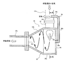
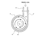
- FIG. 3 is a schematic cross-sectional view of the cyclone type gas-liquid separator 28 shown in FIG. 4 is a cross-sectional view taken along line AA in FIG.
- the cyclonic gas-liquid separator 28 has a cyclone housing 35 into which a mixed fluid of working fluid and air flows.
- the cyclone housing 35 has a cylindrical portion 35a and a truncated cone portion 35b connected to the cylindrical portion 35a.
- the central axis of the cylindrical portion 35a coincides with the central axis of the truncated cone portion 35b.
- a disc-shaped lid 36 is fixed to the end of the cylindrical portion 35a.
- An air vent pipe 38 communicating with the internal space of the cyclone housing 35 is fixed to the center of the lid 36.
- the tip of the truncated cone part 35b is connected to the secondary side circulation line 27b.
- a housing inlet 35c into which the mixed fluid flows is formed in the cylindrical portion 35a.
- the cyclone type gas-liquid separator 28 has an inlet pipe 37 connected to the housing inlet 35c.
- the inlet pipe 37 extends from the housing inlet 35c in the tangential direction of the cylindrical portion 35a. Furthermore, the inlet pipe 37 is connected to the primary side circulation line 27a.
- a housing outlet 35d through which the working fluid from which air has been separated flows out is formed at the tip of the truncated cone part 35b.
- the mixed fluid of the working fluid and air flows into the cyclone housing 35 from the housing inlet 35c through the primary side circulation line 27a and the inlet pipe 37. As shown in FIG. 4, the mixed fluid of the working fluid and air flows into the cyclone housing 35 from the tangential direction of the cylindrical portion 35a. Since the working fluid has a pressure increased by the rotation of the impeller 1, the mixed fluid of the working fluid and air flows into the cyclone housing 35 at a high speed due to its own pressure, and swirls within the cyclone housing 35. Therefore, in this embodiment, since the mixed fluid is swirled in the cyclone housing 35, ancillary equipment such as a pump for increasing the pressure of the working fluid is unnecessary.
- Centrifugal force acts on the mixed fluid swirling in the cyclone housing 35. Since the specific gravity of air is lighter than the specific gravity of the working fluid, the air can be separated from the working fluid by the difference between the centrifugal force acting on the air and the centrifugal force acting on the working fluid.
- the air separated from the working fluid passes through the air vent pipe 38 and is discharged to the outside of the cyclone housing 35, that is, to the outside of the working fluid circulation line 27.
- the working fluid from which the air has been separated flows into the secondary circulation line 27b through the housing outlet 35d, and is returned to the fluid chamber 5 through the fluid cooling device 26 (see FIG. 1).
- air can be separated from the working fluid with a simple configuration in which the cyclonic gas-liquid separator 28 is simply connected to the fluid circulation line 27.
- the cyclone gas-liquid separation device 28 of the present embodiment is horizontally arranged. More specifically, the cylindrical portion 35a and the truncated cone portion 35b of the cyclone housing 35 of the cyclonic gas-liquid separation device 28 are disposed horizontally.
- the cyclonic gas-liquid separator 28 is located below the scoop tube 30.
- the mixed fluid discharged from the scoop tube 30 flows into the cyclone housing 35 through a primary side circulation line 27a extending in a substantially vertical direction. Further, the mixed fluid flows in the horizontal direction from the cylindrical portion 35 a toward the truncated cone portion 35 b while swirling in the cyclone housing 35.
- the working fluid from which the air is separated flows in the horizontal direction as it is, and flows into the fluid cooling device 26 through the secondary side circulation line 27b.
- the air vent pipe 38 for discharging the air separated from the working fluid from the cyclone housing 35 is connected to a communication portion 38 a that is fixed to the lid 36 and communicates with the internal space of the cyclone housing 35.
- the main pipe part 38b extends upward from the communication part 38a, and the horizontal part 38c extends from the main pipe part 38b in the horizontal direction.
- the communication portion 38a extends in the horizontal direction from the center portion of the lid 36, and the main pipe portion 38b extends in the vertical direction.
- An air discharge port 38d is formed at the end of the horizontal portion 38b. The air separated from the working fluid passes through the communication part 38a, the main pipe part 38a and the horizontal part 38b and is discharged from the air discharge port 38d in the horizontal direction.
- the air discharged from the air vent pipe 38 contains mist of working fluid (working oil in this embodiment). Therefore, the air is discharged above the liquid level of the oil stored in the oil tank 9. When the air collides with the oil level stored in the oil tank 9, bubbles may be generated on the oil level. As a result, the amount of oil stored from the oil level gauge 10 may not be confirmed by the bubbles.
- the air separated from the working fluid is discharged from the air discharge port 38c of the air vent pipe 38 in the horizontal direction. Therefore, air does not give an impact to the oil level, and bubbles can be prevented from being generated on the oil level.
- the present invention can be used for a gas-liquid separation device that separates air mixed in a working fluid of a fluid coupling from the working fluid.
Landscapes
- Engineering & Computer Science (AREA)
- General Engineering & Computer Science (AREA)
- Mechanical Engineering (AREA)
- Physics & Mathematics (AREA)
- Fluid Mechanics (AREA)
- Chemical & Material Sciences (AREA)
- Chemical Kinetics & Catalysis (AREA)
- Cyclones (AREA)
- Degasification And Air Bubble Elimination (AREA)
- Separating Particles In Gases By Inertia (AREA)
Abstract
Description
本発明の好ましい態様は、前記サイクロンハウジングには、前記作動流体から分離された空気を水平方向に排出する空気抜き管が接続されることを特徴とする。
本発明の好ましい態様は、前記サイクロン式気液分離装置は、水平に配置されることを特徴とする。
2 ランナ
3 ハウジング本体
5 流体室
7 インペラケーシング
8 ケーシング
9 油タンク
10 油面計
11 駆動軸
12 出力軸
15 入力軸
16,17 ラジアル軸受
21 大歯車
22 小歯車
25 作動流体循環システム
26 流体冷却装置
27 作動流体循環ライン
28 サイクロン式気液分離装置
30 スクープチューブ(すくい管)
31 アクチュエータ
35 サイクロンハウジング
36 蓋
37 入口管
38 空気抜き管
40,41,45,46 ラジアル軸受
42,47 スラスト軸受
50 潤滑油供給システム
51 潤滑油供給ライン
53 油ポンプ
54 油冷却装置
Claims (4)
- 互いに向き合って配置されたインペラおよびランナと、
前記インペラと前記ランナとの間に形成された流体室内にある作動流体の量を増減させるためのスクープチューブと、
前記スクープチューブから前記流体室まで延びる作動流体循環ラインと、
前記作動流体循環ラインに接続され、前記作動流体とともに前記スクープチューブに流入した空気を前記作動流体から分離する気液分離装置を備え、
前記気液分離装置は、前記作動流体と前記空気の混合流体を旋回させることにより、前記空気を前記作動流体から分離するサイクロン式気液分離装置であることを特徴とする流体継手。 - 前記サイクロン式気液分離装置は、前記混合流体が流入するサイクロンハウジングを備え、
前記インペラの回転によって上昇した前記作動流体の圧力により、前記混合流体を前記サイクロンハウジング内で旋回させることを特徴とする請求項1に記載の流体継手。 - 前記サイクロンハウジングには、前記作動流体から分離された空気を水平方向に排出する空気抜き管が接続されることを特徴とする請求項2に記載の流体継手。
- 前記サイクロン式気液分離装置は、水平に配置されることを特徴とする請求項1乃至3のいずれか一項に記載の流体継手。
Priority Applications (1)
| Application Number | Priority Date | Filing Date | Title |
|---|---|---|---|
| KR1020187019395A KR20180094956A (ko) | 2015-12-15 | 2016-10-19 | 유체 커플링 |
Applications Claiming Priority (2)
| Application Number | Priority Date | Filing Date | Title |
|---|---|---|---|
| JP2015244503A JP2017110708A (ja) | 2015-12-15 | 2015-12-15 | 流体継手 |
| JP2015-244503 | 2015-12-15 |
Publications (1)
| Publication Number | Publication Date |
|---|---|
| WO2017104252A1 true WO2017104252A1 (ja) | 2017-06-22 |
Family
ID=59056053
Family Applications (1)
| Application Number | Title | Priority Date | Filing Date |
|---|---|---|---|
| PCT/JP2016/080958 Ceased WO2017104252A1 (ja) | 2015-12-15 | 2016-10-19 | 流体継手 |
Country Status (3)
| Country | Link |
|---|---|
| JP (1) | JP2017110708A (ja) |
| KR (1) | KR20180094956A (ja) |
| WO (1) | WO2017104252A1 (ja) |
Citations (3)
| Publication number | Priority date | Publication date | Assignee | Title |
|---|---|---|---|---|
| JPS6250328U (ja) * | 1985-09-18 | 1987-03-28 | ||
| JPH0518660U (ja) * | 1991-08-19 | 1993-03-09 | 三菱重工業株式会社 | 遠心力を利用する分離装置 |
| WO2014069024A1 (ja) * | 2012-10-29 | 2014-05-08 | 株式会社ティーエヌケー | 液中気泡の分離除去循環システム |
-
2015
- 2015-12-15 JP JP2015244503A patent/JP2017110708A/ja active Pending
-
2016
- 2016-10-19 WO PCT/JP2016/080958 patent/WO2017104252A1/ja not_active Ceased
- 2016-10-19 KR KR1020187019395A patent/KR20180094956A/ko not_active Withdrawn
Patent Citations (3)
| Publication number | Priority date | Publication date | Assignee | Title |
|---|---|---|---|---|
| JPS6250328U (ja) * | 1985-09-18 | 1987-03-28 | ||
| JPH0518660U (ja) * | 1991-08-19 | 1993-03-09 | 三菱重工業株式会社 | 遠心力を利用する分離装置 |
| WO2014069024A1 (ja) * | 2012-10-29 | 2014-05-08 | 株式会社ティーエヌケー | 液中気泡の分離除去循環システム |
Also Published As
| Publication number | Publication date |
|---|---|
| KR20180094956A (ko) | 2018-08-24 |
| JP2017110708A (ja) | 2017-06-22 |
Similar Documents
| Publication | Publication Date | Title |
|---|---|---|
| CN106661875B (zh) | 跨音速两相反动涡轮机 | |
| JP5739589B2 (ja) | 液中気泡の分離除去循環システム | |
| CN104185497B (zh) | 用于曲轴箱气体的清洁的设备 | |
| NO20110061A1 (no) | Rotorseparator og akselkopler for kompressorer | |
| MX2008009436A (es) | Impulsor de alto flujo/de inductor dual/de alta eficiencia para aplicaciones liquidas incluyendo metal fundido. | |
| NO20141139A1 (no) | Fluidseparator | |
| CN106215464A (zh) | 高效双级油液在线除气泡装置 | |
| CN205516904U (zh) | 螺旋加速式油气分离器 | |
| US20210220757A1 (en) | Bubble separator, and fluid circuit for automobile that includes bubble separator | |
| CN107810037B (zh) | 用于清洁曲柄箱气体的设备 | |
| JP6538550B2 (ja) | 潤滑油の漏洩を防止する軸封装置を有する流体継手 | |
| US5435133A (en) | Hydrodynamic clutch | |
| JP6456812B2 (ja) | 水中モータ駆動式ポンプ | |
| WO2017104252A1 (ja) | 流体継手 | |
| CN110787492A (zh) | 能源高效利用的惯性分离装置 | |
| JP5716220B1 (ja) | 流体中気泡の分離除去装置 | |
| JP2021173276A (ja) | 等温圧縮用気液混合圧縮ポンプ | |
| JP4562088B2 (ja) | 自吸式ポンプ | |
| EP4025321B1 (en) | Bubble separator, and fluid circuit including bubble separator for automobile | |
| RU2146227C1 (ru) | Тепломассообменник | |
| CA2229018A1 (en) | Pump/separator apparatus for viscous liquids | |
| RU2506463C1 (ru) | Электронасосный агрегат вертикального типа (варианты) | |
| KR20160140242A (ko) | 사류 펌프 | |
| RU54151U1 (ru) | Роторный кавитационный реактор | |
| CN102606535A (zh) | 一种用于输油主泵的压水室 |
Legal Events
| Date | Code | Title | Description |
|---|---|---|---|
| 121 | Ep: the epo has been informed by wipo that ep was designated in this application |
Ref document number: 16875237 Country of ref document: EP Kind code of ref document: A1 |
|
| NENP | Non-entry into the national phase |
Ref country code: DE |
|
| ENP | Entry into the national phase |
Ref document number: 20187019395 Country of ref document: KR Kind code of ref document: A |
|
| WWE | Wipo information: entry into national phase |
Ref document number: 1020187019395 Country of ref document: KR |
|
| 122 | Ep: pct application non-entry in european phase |
Ref document number: 16875237 Country of ref document: EP Kind code of ref document: A1 |