WO2017104254A1 - Dispositif de climatisation de véhicule - Google Patents
Dispositif de climatisation de véhicule Download PDFInfo
- Publication number
- WO2017104254A1 WO2017104254A1 PCT/JP2016/081100 JP2016081100W WO2017104254A1 WO 2017104254 A1 WO2017104254 A1 WO 2017104254A1 JP 2016081100 W JP2016081100 W JP 2016081100W WO 2017104254 A1 WO2017104254 A1 WO 2017104254A1
- Authority
- WO
- WIPO (PCT)
- Prior art keywords
- refrigerant
- heat exchanger
- outlet
- inlet
- valve
- Prior art date
- Legal status (The legal status is an assumption and is not a legal conclusion. Google has not performed a legal analysis and makes no representation as to the accuracy of the status listed.)
- Ceased
Links
Images






Classifications
-
- B—PERFORMING OPERATIONS; TRANSPORTING
- B60—VEHICLES IN GENERAL
- B60H—ARRANGEMENTS OF HEATING, COOLING, VENTILATING OR OTHER AIR-TREATING DEVICES SPECIALLY ADAPTED FOR PASSENGER OR GOODS SPACES OF VEHICLES
- B60H1/00—Heating, cooling or ventilating devices
-
- B—PERFORMING OPERATIONS; TRANSPORTING
- B60—VEHICLES IN GENERAL
- B60H—ARRANGEMENTS OF HEATING, COOLING, VENTILATING OR OTHER AIR-TREATING DEVICES SPECIALLY ADAPTED FOR PASSENGER OR GOODS SPACES OF VEHICLES
- B60H1/00—Heating, cooling or ventilating devices
- B60H1/22—Heating, cooling or ventilating devices the heat source being other than the propulsion plant
-
- B—PERFORMING OPERATIONS; TRANSPORTING
- B60—VEHICLES IN GENERAL
- B60H—ARRANGEMENTS OF HEATING, COOLING, VENTILATING OR OTHER AIR-TREATING DEVICES SPECIALLY ADAPTED FOR PASSENGER OR GOODS SPACES OF VEHICLES
- B60H1/00—Heating, cooling or ventilating devices
- B60H1/32—Cooling devices
Definitions
- the present disclosure relates to a vehicle air conditioner for heating a vehicle interior.
- Patent Document 1 discloses a vehicle air conditioner using a heat pump system in which an indoor heat exchanger and a water refrigerant heat exchanger are provided in a hot water circuit through which engine coolant flows.
- the water-refrigerant heat exchanger heats engine coolant with high-temperature and high-pressure refrigerant discharged from the compressor.
- the indoor heat exchanger heats the air in the vehicle interior with engine coolant heated by a high-temperature and high-pressure refrigerant.
- the temperature of engine cooling water can be raised rapidly using a high-temperature / high-pressure refrigerant.
- the air temperature in the passenger compartment can be raised rapidly.
- a heat pump system in which an indoor heat exchanger and a water refrigerant heat exchanger are provided in a hot water circuit is referred to as a water heating type heat pump system.
- a heat pump system including an indoor heat exchanger that directly heats air with a refrigerant discharged from a compressor can be considered.
- a heat pump system is referred to as an air heating type heat pump system.
- heat is exchanged between the refrigerant and the air, and heat energy remains in the refrigerant, but the residual heat energy is less than that in the water heating type heat pump system.
- Efficiency refers to the energy given to the compressor to drive the compressor as energy Ea, and the heat energy output from the indoor heat exchanger to the air in the passenger compartment as heat energy En, the heat energy relative to the energy Ea.
- the ratio of En is En / Ea.
- an air heating type heat pump system used for air conditioning of a passenger compartment such as a bus
- a refrigeration cycle in which a refrigerant flow is switched by a four-way valve or the like and an indoor heat exchanger is shared between cooling and heating.
- an indoor heat exchanger it is common to arrange an indoor heat exchanger on the ceiling side in the passenger compartment.
- an object of the present disclosure is to provide a vehicle air conditioner that achieves both efficiency and feeling.
- a vehicle air conditioner includes a first air outlet disposed on a ceiling side in a vehicle interior and a second air outlet disposed on a floor side in the vehicle interior.
- Applies to Vehicle air conditioners A first blower for blowing an air flow; A second blower for blowing an air flow; A first indoor heat exchanger that configures a heat pump cycle that circulates the refrigerant together with a compressor that sucks and compresses and discharges the refrigerant, and heats the air flow blown from the first blower by the refrigerant discharged from the compressor
- a heat exchanger for heating that constitutes the heat pump cycle and heats the heat medium with a refrigerant
- a second indoor heat exchanger that heats the air flow blown from the second blower by the heated heat medium
- a switching control unit A switching control unit.
- the first air outlet blows out the air flow heated by the first indoor heat exchanger into the vehicle interior
- the second air outlet blows out the air flow heated by the second indoor heat exchanger into the vehicle interior. Is heated.
- the switching control unit heats the air flow only by the first indoor heat exchanger out of the first indoor heat exchanger and the second indoor heat exchanger and blows it out from the first outlet.
- Switch between 1 heating mode and 2nd heating mode which heats an air flow only with a 2nd indoor heat exchanger out of a 1st indoor heat exchanger and a 2nd indoor heat exchanger, and blows off from a 2nd outlet .
- the air flow is heated only by the first indoor heat exchanger out of the first indoor heat exchanger and the second indoor heat exchanger and blown out from the first outlet, so that the feeling is felt.
- Efficiency can be prioritized.
- the air flow is heated only by the second indoor heat exchanger out of the first indoor heat exchanger and the second indoor heat exchanger and blown out from the second outlet, so that the feeling is higher than the efficiency.
- the heat medium is a fluid used to move heat.
- FIG. 1st Embodiment It is a block diagram which shows the structure of the vehicle air conditioner in 1st Embodiment, Comprising: It is a figure which shows the warm air which blows off from an indoor heat exchanger in 4th heating mode. It is an arrangement plan of the indoor heat exchanger in the car in the first embodiment, and is a diagram showing the warm air blown out from the indoor heat exchanger in the fourth heating mode.
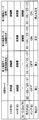
- the chart which shows the operating state of each of an indoor heat exchanger, an outdoor heat exchanger, a water refrigerant condenser, a four-way valve, and the blower outlet which blows off cool air or warm air actually for every air-conditioning mode It is.
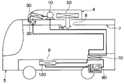
- FIG. 1A is a configuration diagram illustrating a configuration of a vehicle air conditioner 1 according to the first embodiment.
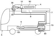
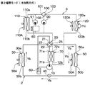
- FIG. 1B is a layout diagram of the indoor heat exchangers 50 and 120 in the automobile 5 according to the first embodiment.
- the vehicle air conditioner 1 is mounted on an automobile 5 such as a bus vehicle.
- the vehicle air conditioner 1 performs air conditioning in the passenger compartment, and includes a refrigeration cycle device 2 and a hot water circuit 3.
- the refrigeration cycle apparatus 2 constitutes a heat pump cycle in which refrigerant is circulated to repeat heat absorption and heat release, and the four-way valve 20 switches the refrigerant flow to switch between cooling and heating.
- This heat pump cycle is a vapor compression refrigeration cycle.
- the refrigeration cycle apparatus 2 forms a closed circuit with refrigerant piping.
- the refrigeration cycle apparatus 2 includes an electric compressor 10, a four-way valve 20, an outdoor heat exchanger 30, an electric expansion valve 40, an indoor heat exchanger 50, a gas-liquid separator 60, a water refrigerant condenser 70, and electric fans 30A and 50A. Prepare.
- the electric compressor 10 includes a compression mechanism that draws in refrigerant, compresses and discharges the refrigerant, and an electric motor that drives the compression mechanism.
- the four-way valve 20 includes a valve mechanism having an outlet 21, an inlet 22, and outlets 23 and 24.
- the valve mechanism is driven by an electric actuator (not shown) so that the inlet 22 is provided at one of the inlets 23 and 24. Connect the outlet 21 to the other entrance.
- the outlet 21 is a valve outlet connected to the refrigerant inlet of the electric compressor 10 via the gas-liquid separator 60.
- the inlet 22 is a valve inlet connected to the refrigerant discharge port of the electric compressor 10 via the water refrigerant condenser 70.
- the inlet / outlet 23 is a first valve inlet / outlet that is connected to the inlet / outlet 30a of the outdoor heat exchanger 30 and serves both as an inlet and an outlet for the refrigerant.
- the inlet / outlet 24 is a second valve inlet / outlet that is connected to the refrigerant inlet / outlet 50a of the indoor heat exchanger 50 and serves both as an inlet and an outlet for the refrigerant.
- the outdoor heat exchanger 30 exchanges heat between the air outside the passenger compartment blown from the electric fan 30A and the refrigerant.
- air outside the passenger compartment is referred to as outside air
- air inside the passenger compartment is referred to as inside air.
- the outdoor heat exchanger 30 includes entrances 30a and 30b that serve both as an inlet and an outlet for the refrigerant.
- the entrance / exit 30a is a first entrance / exit that is connected to the entrance / exit 23 of the four-way valve 20 and serves both as an inlet and an outlet for the refrigerant.
- the entrance / exit 30b is a second entrance / exit that serves both as an inlet and an outlet for the refrigerant, and is connected to the second entrance / exit 50b of the indoor heat exchanger 50 via the electric expansion valve 40.
- the electric expansion valve 40 is disposed between the outdoor heat exchanger 30 and the indoor heat exchanger 50, and adjusts the opening degree of the refrigerant flow path between the outdoor heat exchanger 30 and the indoor heat exchanger 50 by an electric actuator. It is a decompressor.
- the refrigerant channel is a channel through which the refrigerant flows from one heat exchanger to the other heat exchanger of the outdoor heat exchanger 30 and the indoor heat exchanger 50.
- the indoor heat exchanger 50 is an air heating type first indoor heat exchanger that directly heats an air flow blown from the electric fan 50A with a refrigerant.
- the electric fan 50 ⁇ / b> A is a first blower that blows out at least one of the inside air and the outside air supplied from an inside / outside air switching box (not shown) toward the indoor heat exchanger 50.
- the inside / outside air switching box is a device that supplies inside air or outside air to the electric fan 50A.
- the indoor heat exchanger 50 includes refrigerant inlets and outlets 50a and 50b that serve as inlets and outlets for the refrigerant.
- the refrigerant inlet / outlet port 50 a is a first inlet / outlet port connected to the inlet / outlet port 24 of the four-way valve 20.
- the gas-liquid separator 60 is disposed between the outlet 21 of the four-way valve 20 and the refrigerant inlet of the electric compressor 10 to separate the refrigerant flowing from the outlet 21 of the four-way valve 20 into a gas phase refrigerant and a liquid phase refrigerant.
- Gas phase refrigerant is supplied to the refrigerant inlet of the electric compressor 10.
- the water refrigerant condenser 70 is a heating heat exchanger that exchanges heat between the refrigerant and the heat medium, and includes a refrigerant outlet 71a, a refrigerant inlet 71b, a water inlet 72a, and a water outlet 72b.
- the heat medium of the present embodiment is a fluid used for transferring heat, and for example, water to which an antifreeze is added is used.
- the refrigerant inlet 71 b is connected to the refrigerant discharge port of the electric compressor 10.
- the refrigerant outlet 71 a is connected to the inlet 22 of the four-way valve 20.
- the water inlet 72 a is connected to the water outlet of the pump 90, the water outlet of the traveling engine 80, and the water inlet 110 b of the radiator 110.
- the hot water circuit 3 constitutes a closed circuit with water piping through which the heat medium flows.
- the hot water circuit 3 includes pumps 90 and 91, a three-way valve 100, a radiator 110, an indoor heat exchanger 120, and electric fans 110A and 120A.
- the water outlet of the pump 90 is connected to the water inlet 72a of the water refrigerant condenser 70.
- the water outlet of the pump 91 is connected to the water inlet 72 a of the water refrigerant condenser 70 via the exhaust heat portion of the traveling engine 80.
- the traveling engine 80 is an internal combustion engine that applies driving force to driving wheels.
- the exhaust heat unit is a part that discharges exhaust heat from the combustion chamber to the heat medium in the traveling engine 80.
- the three-way valve 100 is provided with a valve mechanism having outlets 101 and 102 and an inlet 103, and the valve mechanism is driven by an electric actuator (not shown) to connect the inlet 103 to one of the outlets 101 and 102.
- This is an electric switching valve.
- the outlet 101 is connected to the water outlet 110a of the radiator 110.
- the outlet 102 is connected to the water inlet of the pump 91.
- the inlet 103 is connected to the water outlet 120 a of the indoor heat exchanger 120.
- the radiator 110 is a heat exchanger that cools the heat medium by outside air blown from the electric fan 110A.
- the water inlet 110 b of the radiator 110 is connected to the water outlet of the pump 91 through the exhaust heat portion of the traveling engine 80.
- the pump 90 circulates the heat medium between the indoor heat exchanger 120 and the water refrigerant condenser 70.
- the pump 91 circulates the heat medium between the exhaust heat section of the traveling engine 80 and the radiator 110, and between the water refrigerant condenser 70 and the indoor heat exchanger 120 via the exhaust heat section of the traveling engine 80. Circulate.
- the indoor heat exchanger 120 is a water heating type second indoor heat exchanger that heats the air flow blown from the electric fan 110A with a heat medium.
- the electric fan 110A sucks the inside air and sends the sucked inside air to the indoor heat exchanger 120 as an air flow.
- the water inlet 120 b of the indoor heat exchanger 120 is connected to the water outlet 72 b of the water refrigerant condenser 70.
- FIG. 1B shows a layout diagram of the indoor heat exchangers 50, 120, etc. constituting the vehicle air conditioner 1 of the present embodiment.
- the indoor heat exchanger 50 of this embodiment comprises the roof installation unit 4 with the electric compressor 10, the four-way valve 20, the outdoor heat exchanger 30, the electric expansion valve 40, the gas-liquid separator 60, and the electric fans 30A and 50A. To do.
- the roof installation unit 4 is installed on the roof surface of the vehicle. In FIG. 1B, illustration of some configurations such as the four-way valve 20, the electric expansion valve 40, the gas-liquid separator 60, the electric fans 30 ⁇ / b> A and 50 ⁇ / b> A, and the refrigerant piping are omitted.
- the vehicle air conditioner 1 is provided with a blower duct 7, a plurality of outlets 8, and a plurality of outlets 9.
- FIG. 1B shows one air outlet 8 and one air outlet 9.
- the air duct 7 is disposed on the ceiling side in the automobile 5 and guides the air flow heated by the indoor heat exchanger 50 to the plurality of outlets 8 side.
- Each of the plurality of air outlets 8 is disposed on the ceiling side of the automobile 5 and opens toward the vehicle interior.
- the indoor heat exchanger 120 is disposed below the seat and below the floor surface. That is, the indoor heat exchanger 120 is arranged on the floor side in the vehicle interior.
- the plurality of air outlets 9 are arranged on the floor side in the passenger compartment and blow out warm air to the feet of the passengers. Specifically, as the plurality of air outlets 9, the air outlets that are arranged below the seat and blow hot air to the passenger's feet, or that are opened on the floor in the passenger compartment and blow the hot air to the passenger's feet. An exit is adopted.
- the vehicle air conditioner 1 includes an electronic control unit 130.
- This electronic control unit 130 is indicated as ECU in FIG. 1A.
- the electronic control device 130 is configured by a microcomputer, a memory, and the like, and performs an air conditioning control process according to a computer program.
- This memory is a non-transitional physical storage medium.
- the vehicle air conditioner 1 performs the air conditioning control process based on the output signals of the temperature sensor 140, the water temperature sensor 141, and the like and the output signal of the operation panel 142, and the electric compressor 10, the four-way valve 20, and the electric fan 30A. , 50A, 110A, 120A, and the three-way valve 100 are controlled.
- the temperature sensor 140 detects the air temperature in the vehicle interior (hereinafter referred to as room temperature Tr).
- the water temperature sensor 141 detects the temperature of the heat medium in the exhaust heat section of the traveling engine 80 (hereinafter referred to as the water temperature Tw).
- the operation panel 142 includes a cooling / heating switching switch that is operated to switch between cooling and heating, a setting switch that is operated to set a set value Tset that is a target temperature of the air temperature in the passenger compartment, and the like.
- the electronic control unit 130 performs any one of the cooling mode and the first to fourth heating modes by performing the air conditioning control process.
- the cooling mode and the first to fourth heating modes will be described separately.
- the cooling mode is an air conditioning mode in which cool air is blown from the air outlet 8 into the vehicle interior.
- the first heating mode is an air conditioning mode in which the air flow is directly heated by the high-temperature and high-pressure refrigerant discharged from the electric compressor 10 and blown out from the outlet 8 into the vehicle interior.
- the second heating mode is an air conditioning mode in which the heat medium is heated by the high-temperature and high-pressure refrigerant discharged from the electric compressor 10, the air flow is heated by the heated heat medium, and the air is blown out from the outlet 9 into the vehicle interior.
- the third heating mode is an air conditioning mode in which the first heating mode and the second heating mode are combined to blow warm air from the outlets 8 and 9 into the vehicle interior.
- the fourth heating mode is an air conditioning mode in which the heat medium is heated by the exhaust heat of the combustion chamber of the traveling engine 80 and the air flow is heated by the heated heat medium and blown out from the outlet 9 into the vehicle interior.
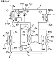
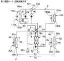
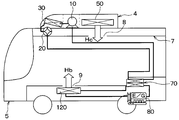
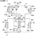
- FIG. 3A, FIG. 4A, FIG. 5A, and FIG. 6A are configuration diagrams showing the configuration of the vehicle air conditioner, and for each air conditioning mode, cool air, hot air blowing, and refrigerant flows Ya, Yb, Yd is shown.
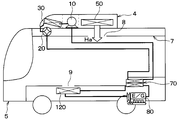
- 2B, FIG. 3B, FIG. 4B, FIG. 5B, and FIG. 6B are layout diagrams of the indoor heat exchangers 50 and 120 in the automobile, and show cool air and hot air blowing for each air conditioning mode.
- 2B, FIG. 3B, FIG. 4B, FIG. 5B, and FIG. 6B are similar to FIG. 1B.
- an arrow Ha indicates cold air blown from the indoor heat exchanger 50
- an arrow Hb indicates hot air blown from the indoor heat exchanger 50
- Arrows Hc and Hd indicate hot air blown out from the indoor heat exchanger 120.
- FIGS. 3A and 3B show the first heating mode
- FIGS. 4A and 4B show the second heating mode
- FIGS. 5A and 5B show the third heating mode
- 6A and 6B show the fourth heating mode.
- FIG. 7 shows the operating states of the indoor heat exchanger 50, the outdoor heat exchanger 30, the water refrigerant condenser 70, and the four-way valve 20 for each air conditioning mode, and the outlets that actually blow out cold air and hot air. Show.
- the indoor heat exchanger 50 and the outdoor heat exchanger 30 and the water refrigerant condenser 70 are represented as IHE, XHE, and W / CCnd, respectively, in the drawing.
- “overhead” indicates the indoor heat exchanger 50 and the outlet 8
- “foot” indicates the indoor heat exchanger 120 and the outlet 9.
- the cooling mode First, the cooling mode will be described.
- the electronic control unit 130 controls the electric compressor 10, the four-way valve 20, the electric expansion valve 40, the electric fans 30A, 50A, 110A, 120A, the pumps 90 and 91, and the three-way valve 100, respectively.
- the inlet 22 and the outlet 23 are connected, and the inlet 24 and the outlet 21 are connected.
- the electric compressor 10 sucks and compresses the refrigerant from the gas-liquid separator 60 and discharges the high-temperature and high-pressure refrigerant.
- the high-temperature and high-pressure refrigerant passes through the water refrigerant condenser 70 and the inlet 22 and outlet 23 of the four-way valve 20 and then passes through the outdoor heat exchanger 30, the electric expansion valve 40, and the indoor heat exchanger 50 as indicated by the arrow Ya. It flows in order.
- the outdoor heat exchanger 30 In the outdoor heat exchanger 30, the high-temperature and high-pressure refrigerant radiates heat to the air flow blown from the electric fan 30A. At this time, the outdoor heat exchanger 30 functions as a condenser in which the refrigerant is cooled and condensed by the air flow, as shown in FIG.
- the refrigerant that has passed through the outdoor heat exchanger 30 is decompressed and expanded by the electric expansion valve 40.
- the decompressed and expanded refrigerant cools the air flow blown from the electric fan 50A in the indoor heat exchanger 50.
- the indoor heat exchanger 50 functions as an evaporator that absorbs heat from the air flow and evaporates the refrigerant.
- the cooled air flow passes through the blower duct 7 and then blows out from the plurality of outlets 8 into the vehicle interior as indicated by the arrow Ha in FIG. 2B.
- cold air is blown out from the passenger's head into the passenger compartment.
- the temperature of the indoor heat exchanger 50 is controlled by the electronic control device 130 controlling the refrigerant capacity discharged from the electric compressor 10 and the opening degree of the refrigerant flow path of the electric expansion valve 40. Become. As a result, the room temperature Tr detected by the temperature sensor 140 approaches the set value Tset.
- the refrigerant that has passed through the indoor heat exchanger 50 in FIG. 2A flows through the inlet / outlet 24 and the outlet 21 of the four-way valve 20 and then flows into the gas-liquid separator 60.
- This refrigerant is separated into a gas-phase refrigerant and a liquid-phase refrigerant in the gas-liquid separator 60, and the gas-phase refrigerant is sucked into the electric compressor 10.
- the pump 91 operates. For this reason, the heat medium is circulated between the exhaust heat section of the traveling engine 80 and the radiator 110. For this reason, the heat medium absorbs heat from the combustion chamber at the exhaust heat portion of the traveling engine 80. In radiator 110, the heat medium radiates heat to the air flow blown from electric fan 110A.
- the first heating mode is an air conditioning mode in which an air flow is heated only by the indoor heat exchanger 50 out of the indoor heat exchangers 50 and 120 and blown out from the plurality of outlets 8.
- the control processing of the four-way valve 20 by the electronic control device 130 is different between the first heating mode and the cooling mode.
- the electronic control unit 130 controls the four-way valve 20 to connect the inlet 22 and the outlet 24 and connect the inlet 23 and the outlet 21.
- the high-temperature and high-pressure refrigerant discharged from the electric compressor 10 passes through the water refrigerant condenser 70 and the inlet 22 and the outlet 24 of the four-way valve 20, and then performs indoor heat exchange as indicated by an arrow Yb in FIG. 3A.
- the indoor heat exchanger 50 In the indoor heat exchanger 50, the high-temperature and high-pressure refrigerant heats the air flow blown from the electric fan 50A. At this time, the indoor heat exchanger 50 functions as a condenser in which the refrigerant is cooled and condensed by the air flow, as shown in FIG. For this reason, the air flow (that is, warm air) heated by the high-temperature and high-pressure refrigerant passes through the air duct 7 and then blows out from the plurality of outlets 8 into the vehicle interior as indicated by the arrow Hb in FIG. 3B. That is, warm air is blown out from the passenger's head into the passenger compartment, and the passenger compartment is heated.
- the air flow that is, warm air heated by the high-temperature and high-pressure refrigerant passes through the air duct 7 and then blows out from the plurality of outlets 8 into the vehicle interior as indicated by the arrow Hb in FIG. 3B. That is, warm air is blown out from the passenger's head into
- the temperature of the indoor heat exchanger 50 is controlled by the electronic control device 130 controlling the refrigerant capacity discharged from the electric compressor 10 and the opening degree of the refrigerant flow path of the electric expansion valve 40. Become. As a result, the room temperature Tr detected by the temperature sensor 140 approaches the set value Tset.
- the refrigerant that has passed through the indoor heat exchanger 50 in FIG. 3A is decompressed and expanded by the electric expansion valve 40.
- the decompressed and expanded refrigerant absorbs heat from the air flow blown from the electric fan 50 ⁇ / b> A in the outdoor heat exchanger 30.
- the outdoor heat exchanger 30 functions as an evaporator that absorbs heat from the air flow from the electric fan 50A and evaporates the refrigerant.
- the refrigerant that has passed through the outdoor heat exchanger 30 passes through the inlet / outlet 23 and the outlet 21 of the four-way valve 20 and then flows into the gas-liquid separator 60.
- This refrigerant is separated into a gas-phase refrigerant and a liquid-phase refrigerant in the gas-liquid separator 60, and the gas-phase refrigerant is sucked into the electric compressor 10.
- the second heating mode is an air conditioning mode in which the air flow is heated only by the indoor heat exchanger 120 out of the indoor heat exchangers 50 and 120 and blown out from the plurality of outlets 9.
- the control processing of the pump 90 and the electric fans 120A and 50A by the electronic control device 130 is different between the second heating mode and the first heating mode.
- the electronic control device 130 operates the pump 90.
- the electronic control unit 130 operates the electric fan 120A and stops the electric fan 50A.
- the electronic control unit 130 controls the four-way valve 20 as in the first heating mode. For this reason, in the refrigeration cycle apparatus 2, the refrigerant circulates as in the first heating mode.
- the heat medium pumped by the pump 90 flows and circulates in the order of the water refrigerant condenser 70, the indoor heat exchanger 120, and the pump 90.
- the water refrigerant condenser 70 the high-temperature and high-pressure refrigerant discharged from the electric compressor 10 heats the heat medium. That is, the water refrigerant condenser 70 functions as a condenser in which the refrigerant is cooled and condensed by the heat medium.
- the heat medium heated by the water refrigerant condenser 70 heats the air flow blown from the electric fan 120A.
- the airflow (that is, warm air) heated by the heat medium is blown out from the plurality of air outlets 9 into the vehicle interior as indicated by an arrow Hc in FIG. 4B. That is, warm air is blown out from the feet of the passengers into the passenger compartment.
- the electronic control device 130 controls the refrigerant capacity discharged from the electric compressor 10 and the opening degree of the refrigerant flow path of the electric expansion valve 40, so that the temperature of the water refrigerant condenser 70 and the indoor heat exchanger 120 is adjusted. Will be controlled. As a result, the room temperature Tr detected by the temperature sensor 140 approaches the set value Tset.
- the third heating mode is an air conditioning mode that combines the first heating mode and the second heating mode.
- the main difference between the third heating mode and the second heating mode is that the electric fans 120A and 50A are operated by the electronic control unit 130, respectively.
- the air flow blown from the electric fan 120A is heated by the heat medium that has passed through the water refrigerant condenser 70 as in the second heating mode. For this reason, the airflow (that is, warm air) heated by the heat medium is blown out from the plurality of outlets 9 into the vehicle interior as indicated by an arrow Hb in FIG. 5B.
- the air flow blown from the electric fan 50A is heated by the high-temperature and high-pressure refrigerant as in the first heating mode. For this reason, the air flow heated by the high-temperature and high-pressure refrigerant (that is, warm air) passes through the air duct 7 and then blows out from the plurality of air outlets 8 into the vehicle interior as indicated by the arrow Hb in FIG. 5B.
- the high-temperature and high-pressure refrigerant that is, warm air
- the water refrigerant condenser 70 and the indoor heat exchanger 50 function as a condenser in which the refrigerant is cooled and condensed by the air flow, as shown in FIG.
- the electronic control unit 130 controls the electric fans 120A and 50A to reduce the amount of air blown from the electric fan 120A compared to the amount of air blown from the electric fan 50A.
- the warm air temperature which blows off from the several blower outlet 9 can be made higher than the warm air temperature which blows off from the several blower outlet 8. FIG. For this reason, the feeling given to the passenger can be improved.
- (4th heating mode) In the fourth heating mode, the electric compressor 10 is stopped, the heat medium is heated by the exhaust heat of the combustion chamber of the traveling engine 80, the air flow is heated by the heated heat medium, and the vehicle is It is an air conditioning mode that blows out indoors.
- the electronic control unit 130 controls the three-way valve 100 to connect only the outlet 101 and the inlet 103 among the outlets 101 and 102. For this reason, with the operation of the pump 91, the heat medium from the pump 91 is heated by the exhaust heat portion of the traveling engine 80, and a part of the heated heat medium is the radiator 110, It flows in the order of the pump 91. In radiator 110, the heat medium is cooled by the air flow blown from electric fan 110A.
- the remaining heat medium other than a part of the heat medium that has flowed to the water inlet 110b side of the radiator 110 is the water refrigerant condenser 70, the indoor heat exchanger. 120, the three-way valve 100, and the pump 91 flow in this order.
- the indoor heat exchanger 120 the airflow blown from the electric fan 120A is heated by the heat medium and blown out from the plurality of outlets 9 into the vehicle interior as indicated by the arrow Hd in FIG. 6B. That is, warm air is blown out from the feet of the passengers into the passenger compartment.
- the cooling mode and the first to fourth heating modes are performed.
- the fourth heating mode is set. carry out. Thereby, the vehicle interior can be heated by effectively using the exhaust heat of the traveling engine 80.
- the electronic control device 130 determines that the temperature of the heat medium in the exhaust heat section of the traveling engine 80 is lower than a predetermined temperature based on the output signal of the water temperature sensor 141, the first heating mode and the second heating mode are performed. Any one of the mode and the third heating mode is performed.
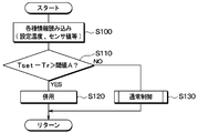
- FIG. 8 is a flowchart showing the selection process in the electronic control unit 130.
- FIG. 9 is a flowchart showing details of step S130 in FIG.
- the electronic control device 130 executes a computer program stored in advance in the memory according to the flowcharts of FIGS.
- step S100 the set value Tset set by the operation panel 142 and the room temperature Tr detected by the temperature sensor 140 are read.
- step S110 it is determined whether or not the difference Tset ⁇ Tr between the set value Tset and the room temperature Tr is larger than the threshold value A.
- the electronic control device 130 corresponds to the capability determination unit by executing step S110.
- the difference Tset ⁇ Tr indicates the heating capacity necessary for heating the vehicle interior by the indoor heat exchangers 50 and 120.
- the heating capacity increases as the difference Tset-Tr increases.
- the heating capacity is an ability to transfer heat from the indoor heat exchangers 50 and 120 to the air flow.
- the difference Tset ⁇ Tr is larger than the threshold value A.
- the heating capacity necessary for heating the passenger compartment becomes larger than a predetermined value, and the electronic control unit 130 determines YES in step S110.
- step S120 the electronic control unit 130 performs the third heating mode in which hot air is blown out using the indoor heat exchangers 120 and 50 together.
- Warm-up is an excessive state from the start of the control until the steady state is reached in the air conditioning control in the passenger compartment.
- the electronic control unit 130 determines NO in step S110, assuming that the heating capacity necessary for heating the passenger compartment is equal to or less than a predetermined value. Accordingly, in step S130, the electronic control unit 130 performs a normal process and performs one of the first heating mode and the second heating mode.
- step S131 of FIG. 9 it is determined whether or not the power consumption P consumed by the electric compressor 10 for heating the passenger compartment is larger than the threshold value B.
- the power consumption P is, for example, power consumption when it is assumed that the second heating mode is performed.
- the power consumption P is positively correlated with the electric energy Ed consumed by the electric compressor 10 for heating the passenger compartment.
- the electronic control unit 130 determines whether or not the electrical energy Ed is greater than the second threshold value.
- the power consumption P is obtained based on the difference Tset ⁇ Tr. As the difference Tset-Tr increases, the power consumption P increases.
- the second threshold corresponds to the reference value.
- step S131 when the power consumption P is greater than the threshold value B, the electronic control device 130 determines that the electrical energy Ed is greater than the second threshold value and determines YES. In this case, the electronic control unit 130 performs the first heating mode in step S132. As a result, the vehicle interior is heated by the air heating type indoor heat exchanger 50.
- step S131 when the power consumption P is equal to or less than the threshold value B, the electronic control device 130 determines NO, assuming that the electric energy Ed is equal to or less than the second threshold value. In this case, the electronic control unit 130 performs the second heating mode in step S133. Thereby, the vehicle interior is heated by the water heating type indoor heat exchanger 120.
- the vehicle air conditioner 1 includes the indoor heat exchanger 50 that heats the air flow blown from the electric fan 50A by the high-temperature and high-pressure refrigerant discharged from the electric compressor 10, and And a water refrigerant condenser 70 that heats a heat medium that absorbs heat from the combustion chamber of the engine 80 with a high-temperature and high-pressure refrigerant.
- the vehicle air conditioner 1 includes an indoor heat exchanger 120 that heats an air flow blown from the electric fan 120 ⁇ / b> A by a heat medium heated by the water refrigerant condenser 70.
- the plurality of air outlets 8 are arranged on the ceiling side of the automobile 5 and open toward the vehicle interior.
- the plurality of air outlets 9 are arranged on the floor side in the passenger compartment and blow out warm air to the feet of the passengers.
- the electronic control unit 130 switches one heating mode between the first heating mode and the second heating mode from the other heating mode.
- the first heating mode is an air conditioning mode in which the air flow is heated only by the indoor heat exchanger 50 out of the indoor heat exchangers 50 and 120 and blown out from the outlet 8. For this reason, the first heating mode can prioritize efficiency over feeling.
- the second heating mode is an air conditioning mode in which the air flow is heated only by the indoor heat exchanger 120 out of the indoor heat exchangers 50 and 120 and blown out from the outlet 9. In the second heating mode, the feeling can be prioritized over the efficiency.
- the vehicle air conditioner 1 can achieve both efficiency and feeling.
- the first heating mode in order to improve the feeling to some extent, it is possible to lower the temperature of the air blown from the air outlet 8 and increase the air volume from the air outlet 8.
- the second heating mode although the temperature at the air outlet 9 can be increased, the air volume from the air outlet 8 cannot be increased in order to increase the air temperature. For this reason, by switching between the first heating mode and the second heating mode, heating can be performed by combining the advantages of the first and second heating modes such as the blowing temperature and the air volume.
- the inventor has studied a system including a refrigeration cycle apparatus that heats hot water using a high-temperature and high-pressure refrigerant discharged from a compressor and a combustor that heats hot water using exhaust heat in a vehicle air conditioner.
- the inventor has studied to preferentially operate one having higher efficiency among the refrigeration cycle apparatus and the combustor when generating hot water used for heating in this system.
- the water heating type heat pump system that heats the air in the passenger compartment with the heat medium requires a water refrigerant condenser that heats the heat medium with the refrigerant.
- the number of heat exchangers is the same as in the case of the water heating type heat pump system, and there are few changes in the configuration of the water heating type heat pump system. For this reason, the vehicle air conditioner 1 of this embodiment can be implemented easily.
- the electronic control device 130 stops the pump 90 when the first heating mode is performed. Therefore, when the first heating mode is performed, the flow of the heat medium through the water refrigerant condenser 70 is stopped. Thereby, it is possible to prevent the heat of the refrigerant from being transmitted to the heat medium in the water refrigerant capacitor 70 in advance.
- the pump 90 since the pump 90 is operated when the second heating mode is performed, the water refrigerant condenser 70 can heat the heat medium favorably with the refrigerant.
- the heat of the refrigerant in the first heating mode, the heat of the refrigerant is directly transmitted to the air in the vehicle interior, whereas in the second heating mode, the heat of the refrigerant is transmitted to the air in the vehicle interior via the heat medium.
- 2nd heating mode has much residual energy compared with 1st heating mode, and its efficiency is low.
- the electric energy given to the electric compressor 10 to drive the electric compressor 10 is referred to as electric energy Ed
- the heat energy output from the indoor heat exchangers 50 and 120 to the air in the passenger compartment is referred to as heat energy Em.
- the efficiency is the ratio En / Em of the thermal energy Em to the electrical energy Ed.
- the amount of heat output from the indoor heat exchanger 50 to the air flow may be the same as the amount of heat output from the indoor heat exchanger 120 to the air flow.
- the electric energy for driving the electric compressor 10 in the second heating mode is larger than the electric energy for driving the electric compressor 10 in the first heating mode.
- the electronic control device 130 performs the first heating mode when the power consumption P is equal to or greater than the first threshold, and performs the second heating mode when the power consumption P is less than the first threshold. .
- the electrical energy consumed in the first heating mode can be brought closer to the electrical energy consumed in the second heating mode. Therefore, the electric energy consumed by the 1st heating mode and the 2nd heating mode can be averaged.
- the air flow is heated by both of the indoor heat exchangers 50 and 120 and the plurality of outlets 9 and the plurality of outlets are heated. Blow out from outlet 8. For this reason, the air temperature in the passenger compartment can be increased in a short time.
- the refrigerant inlet 71b of the water refrigerant condenser 70 is connected to the refrigerant outlet of the electric compressor 10, and the refrigerant outlet 71a of the water refrigerant condenser 70 is connected to the inlet 22 of the four-way valve 20. Therefore, either the cooling mode or the first to fourth heating modes can be performed without using an opening / closing valve other than the four-way valve 20 and without greatly changing the configuration of the refrigerant circuit.
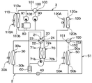
- FIG. 10 shows a configuration of the vehicle air conditioner 1 of the present embodiment.
- the bypass refrigerant flow path 51 is disposed in parallel with the indoor heat exchanger 50 between the inlet / outlet 24 of the four-way valve 20 and the electric expansion valve 40.
- the bypass refrigerant flow path 51 is a refrigerant flow path for bypassing the indoor heat exchanger 50 and flowing the refrigerant flowing through the electric expansion valve 40 from the inlet / outlet 30 b of the outdoor heat exchanger 30 to the inlet / outlet 24 of the four-way valve 20.
- the three-way valve 150 includes a valve mechanism having inlets and outlets 151 and 152 and an outlet 153.
- the valve mechanism is driven by an electric actuator (not shown) to connect the outlet 153 to one of the inlets and outlets 151 and 152. This is a well-known electric switching valve.
- the entrance / exit 151 is an entrance / exit that serves both as an outlet and an inlet for the refrigerant, and is connected to the entrance / exit 24 of the four-way valve 20.
- the entrance / exit 152 is an entrance / exit that serves as both an exit and an entrance for the refrigerant, and is connected to the refrigerant entrance / exit 50a of the indoor heat exchanger 50.
- the outlet 153 is connected to the bypass refrigerant channel 51.
- the electronic control unit 130 controls the four-way valve 20, the pumps 90 and 91, the three-way valve 100, and the like other than the three-way valve 150 in the same manner as in the first embodiment. Therefore, the control of the three-way valve 150 will be mainly described in the cooling mode and the first to third heating modes.
- the electronic control unit 130 controls the three-way valve 150 in the cooling mode to connect only the entrance / exit 152 of the entrance / exit 152 and the exit 153 to the entrance / exit 151. Accordingly, the three-way valve 150 allows the refrigerant to flow into the indoor heat exchanger 50 and prohibits the refrigerant from flowing into the bypass refrigerant flow path 51.
- the refrigerant discharged from the electric compressor 10 passes through the water refrigerant condenser 70, the inlet 22 of the four-way valve 20, and the inlet / outlet 23 of the four-way valve 20 in this order.
- the refrigerant is the outdoor heat exchanger 30, the electric expansion valve 40, the indoor heat exchanger 50, the inlet / outlet 152 of the three-way valve 150, the inlet / outlet 151 of the three-way valve 150, the inlet / outlet 24 of the four-way valve 20, the outlet 21 of the four-way valve 20, It flows in the order of the gas-liquid separator 60 and the refrigerant inlet of the electric compressor 10.
- the electronic control unit 130 controls the three-way valve 150 to connect only the entrance / exit 152 and the entrance / exit 151 out of the entrance / exit 152 and the exit 153 in the first heating mode.
- the refrigerant discharged from the electric compressor 10 passes through the water refrigerant condenser 70, the inlet 22 of the four-way valve 20, and the inlet / outlet 24 of the four-way valve 20 in this order. Thereafter, the refrigerant is the inlet / outlet 151 of the three-way valve 150, the inlet / outlet 152 of the three-way valve 150, the indoor heat exchanger 50, the electric expansion valve 40, the outdoor heat exchanger 30, the inlet / outlet 23 of the four-way valve 20, the outlet 21 of the four-way valve 20, It flows in the order of the gas-liquid separator 60 and the refrigerant inlet of the electric compressor 10.
- the electronic control unit 130 controls the three-way valve 150 in the second heating mode to connect only the outlet 153 and the inlet / outlet 151 out of the inlet / outlet 152 and the outlet 153. Accordingly, the three-way valve 150 prohibits the refrigerant from flowing into the indoor heat exchanger 50 and allows the refrigerant to flow into the bypass refrigerant flow path 51.
- the refrigerant discharged from the electric compressor 10 passes through the water refrigerant condenser 70, the inlet 22 of the four-way valve 20, and the inlet / outlet 24 of the four-way valve 20 in this order. Thereafter, the refrigerant is the inlet 151 of the three-way valve 150, the outlet 153 of the three-way valve 150, the bypass refrigerant flow path 51, the electric expansion valve 40, the outdoor heat exchanger 30, the inlet / outlet 23 of the four-way valve 20, the outlet 21 of the four-way valve 20, It flows in the order of the gas-liquid separator 60 and the refrigerant inlet of the electric compressor 10.
- the electronic control unit 130 controls the three-way valve 150 in the third heating mode, similarly to the first heating mode of the present embodiment. For this reason, the refrigerant
- the electronic control unit 130 controls the three-way valve 150 in the second heating mode to connect only the outlet 153 and the inlet / outlet 151 out of the inlet / outlet 152 and the outlet 153. For this reason, the refrigerant discharged from the electric compressor 10 passes through the water refrigerant condenser 70, the inlet 22 of the four-way valve 20, and the inlet / outlet 24 of the four-way valve 20 in this order. Thereafter, the refrigerant passes through the inlet / outlet 151 of the three-way valve 150 and the outlet 153 of the three-way valve 150 in this order, and then flows to the electric expansion valve 40 side, bypassing the indoor heat exchanger 50.
- the refrigerant discharged from the electric compressor 10 bypasses the indoor heat exchanger 50 and flows toward the electric expansion valve 40 as described above. For this reason, in the indoor heat exchanger 50, it is possible to prevent the refrigerant from radiating heat to the air flow generated by natural convection.
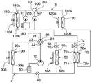
- FIG. 11 shows the configuration of the vehicle air conditioner 1 of the present embodiment.
- the arrangement of the water refrigerant condenser 70 is different from that of the refrigeration cycle apparatus 2 of the above embodiment, and on-off valves 52 and 73 are added.
- the on-off valve 52 is a second on-off valve that is disposed between the inlet / outlet 24 of the four-way valve 20 and the electric expansion valve 40 and opens and closes the refrigerant flow path 53. More specifically, the on-off valve 52 may be disposed between the inlet / outlet 24 of the four-way valve 20 and the refrigerant inlet / outlet 50 a of the indoor heat exchanger 50.
- the refrigerant channel 53 is a channel through which the refrigerant flows between the inlet / outlet 24 of the four-way valve 20 and the electric expansion valve 40, and is arranged in series with the indoor heat exchanger 50.
- the on-off valve 73 is a first on-off valve that is disposed between the inlet / outlet 24 of the four-way valve 20 and the electric expansion valve 40 and opens and closes the refrigerant flow path 74. More specifically, the on-off valve 73 may be disposed between the inlet / outlet 24 of the four-way valve 20 and the refrigerant inlet 71 b of the water refrigerant condenser 70.
- the refrigerant channel 74 is a channel through which the refrigerant flows between the inlet / outlet 24 of the four-way valve 20 and the electric expansion valve 40, and is arranged in series with the water refrigerant capacitor 70.
- the refrigerant flow paths 53 and 74 are arranged in parallel between the inlet / outlet port 24 of the four-way valve 20 and the electric expansion valve 40.
- the on-off valves 52 and 73 for example, electromagnetic valves or electric valves can be used.
- the refrigerant inlet 71b of the water refrigerant condenser 70 is connected to the inlet / outlet 24 of the four-way valve 20, and the refrigerant outlet 71a of the water refrigerant condenser 70 is connected to the electric expansion valve 40.
- the electronic control device 130 controls the four-way valve 20, the pumps 90 and 91, the three-way valve 100, and the like other than the on-off valves 52 and 73 in the same manner as the first embodiment. Therefore, the control of the on-off valves 52 and 73 will be mainly described in the cooling mode and the first to third heating modes.
- the electronic control unit 130 opens the refrigerant channel 53 by the on-off valve 52 and closes the refrigerant channel 74 by the on-off valve 73.
- the refrigerant discharged from the electric compressor 10 passes through the inlet 22 of the four-way valve 20 and the inlet / outlet 23 of the four-way valve 20 in this order.
- the refrigerant is the outdoor heat exchanger 30, the electric expansion valve 40, the indoor heat exchanger 50, the on-off valve 52, the refrigerant flow path 53, the inlet / outlet 24 of the four-way valve 20, the outlet 21 of the four-way valve 20, and the gas-liquid separator 60.
- the refrigerant flows in the order of the refrigerant inlet of the electric compressor 10. For this reason, heat exchange is performed between the refrigerant and the air flow in the indoor heat exchanger 50.
- the electronic control unit 130 controls the on-off valves 52 and 73 in the first heating mode, similarly to the cooling mode of the present embodiment.
- the refrigerant discharged from the electric compressor 10 passes through the inlet 22 of the four-way valve 20 and the inlet / outlet 24 of the four-way valve 20 in this order. Thereafter, the refrigerant is the on-off valve 52, the refrigerant flow path 53, the indoor heat exchanger 50, the electric expansion valve 40, the outdoor heat exchanger 30, the inlet / outlet port 23 of the four-way valve 20, the outlet port 21 of the four-way valve 20, and the gas-liquid separator 60.
- the refrigerant flows in the order of the refrigerant inlet of the electric compressor 10. For this reason, heat exchange is performed between the refrigerant and the air flow in the indoor heat exchanger 50.
- the electronic control unit 130 closes the refrigerant flow path 53 by the opening / closing valve 52 and opens the refrigerant flow path 74 by the opening / closing valve 73.
- the refrigerant discharged from the electric compressor 10 passes through the inlet 22 of the four-way valve 20 and the inlet / outlet 24 of the four-way valve 20 in this order.
- the refrigerant is the on-off valve 73, the refrigerant flow path 74, the refrigerant inlet 71b of the water refrigerant condenser 70, the refrigerant outlet 71a of the water refrigerant condenser 70, the electric expansion valve 40, the outdoor heat exchanger 30, the inlet / outlet 23 of the four-way valve 20, It flows in the order of the outlet 21 of the four-way valve 20, the gas-liquid separator 60, and the refrigerant inlet of the electric compressor 10. For this reason, heat exchange is performed between the refrigerant and the heat medium in the water refrigerant condenser 70.
- the electronic control unit 130 opens the refrigerant flow path 53 by the opening / closing valve 52 and opens the refrigerant flow path 74 by the opening / closing valve 73.
- some of the refrigerant discharged from the electric compressor 10 through the inlet 22 and the inlet / outlet 24 of the four-way valve 20 includes the on-off valve 73, the refrigerant flow path 74, the refrigerant inlet 71b of the water refrigerant condenser 70, the water refrigerant. It flows in the order of the refrigerant outlet 71a of the condenser 70 and the electric expansion valve 40.
- the remaining refrigerant other than a part of the refrigerant flowing toward the on-off valve 73 side includes the on-off valve 52, the refrigerant flow path 53, It flows in the order of the indoor heat exchanger 50 and the electric expansion valve 40.
- the electronic control unit 130 can control the four-way valve 20 and the on-off valves 52 and 73 to perform any one of the cooling mode and the first to fourth heating modes.
- the on-off valve 73 closes the refrigerant flow path 74 in the first heating mode, it is possible to prevent the refrigerant from being circulated wastefully between the electric compressor 10 and the water refrigerant condenser 70. For this reason, the water refrigerant condenser 70 can prevent the refrigerant from heating the heat medium wastefully.
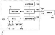
- FIG. 12 shows the electrical configuration of the automobile 5 of the present embodiment.
- the automobile 5 includes a battery 161 and a control device 162 for charge control.
- the battery 161 is a high voltage battery that supplies electric power to the electric motor 160 for traveling and the electric compressor 10.
- the charging control device 162 performs control for charging the battery 161 by the charging device 170 via communication with the charging device 170.
- the charging device 170 is installed in a parking lot or a garage, and includes a charging cable 171.
- the charging cable 171 is used to connect the automobile 5 and supply power to the battery 161. Communication between the charging control device 162 and the charging device 170 is performed via a wiring in the charging cable 171 or the like.
- the traveling motor 160 is an electric motor that applies driving force to the driving wheels.
- the electronic control device 130 of the present embodiment performs a pre-air conditioning control process that implements the first heating mode as pre-air conditioning based on a communication signal from the charging control device 162.
- the communication signal from the charging control device 162 includes information on whether or not the battery 161 is being charged by the charging device 170.
- the pre-air conditioning is to air-condition the passenger compartment before the occupant gets into the automobile 5.
- a timer setting unit for setting a pre-air-conditioning implementation time zone that is, a start time and an end time
- FIG. 13 is a flowchart showing the pre-air conditioning control process of the electronic control device 130.
- the electronic control device 130 executes pre-air conditioning control processing according to the flowchart of FIG.
- step S ⁇ b> 200 the electronic control device 130 determines whether or not the battery 161 is being charged by the charging device 170 based on the communication signal from the charging control control device 162.
- the electronic control device 130 corresponds to the charge determination unit by executing step S200.
- step S200 the electronic control device 130 determines that the battery 161 is not charged by the charging device 170 based on the communication signal from the charging control device 162 and determines NO in step S200.
- step S200 the electronic control device 130 repeats the NO determination in step S200. Thereafter, when charging of battery 161 by charging device 170 is started, electronic control device 130 determines YES in step S200.
- the electronic control unit 130 determines whether or not pre-air conditioning is requested. Specifically, it is determined whether or not the current time is in the pre-air-conditioning implementation time zone set by the timer setting unit of the operation panel 142.
- the electronic control device 130 corresponds to the request determination unit by executing step S210.
- step S210 determines NO in step S210 because pre-air-conditioning is not requested. . Then, the electronic control unit 130 returns to step S210. For this reason, as long as the current time is out of the pre-air conditioning implementation time zone, the electronic control device 130 repeats the NO determination in step S210.
- the electronic control unit 130 determines YES in step S210 because pre-air-conditioning is requested.
- step S220 the electronic control unit 130 performs the first heating mode using the air heating type indoor heat exchanger 50 as pre-air conditioning.
- step S200 the electronic control unit 130 returns to step S200. After that, as long as it is determined that the battery 161 is being charged by the charging device 170 and pre-air conditioning is required, the YES determination in step S200, the YES determination in step S210, and the first heating mode are repeated. .
- the electronic control device 130 when it is determined that the battery 161 is being charged by the charging device 170 and pre-air conditioning is required, the electronic control device 130 performs the first heating mode and performs pre-air conditioning. I do. Thereby, heating of the vehicle interior with high efficiency can be performed. In this case, since there is no occupant in the vehicle compartment, even if the first heating mode is performed, the deterioration of the feeling given to the occupant does not matter.
- the electronic control apparatus 130 demonstrated the example which implemented 1st heating mode in step S220. However, instead of this, the electronic control unit 130 may perform the third heating mode in which the indoor heat exchangers 120 and 50 are used in combination in step S220. Thereby, the air temperature in a vehicle interior can be raised in a short time.
- the vehicle air conditioner 1 of the first embodiment may be applied to an electric vehicle including only the traveling motor 160 among the traveling engine 80 and the traveling motor 160.
- the electronic control unit 130 detects the number of occupants, and when the detected number of occupants is less than the predetermined number, the first heating mode is performed, and the occupant When the number of persons is equal to or greater than the predetermined number, the second heating mode may be performed.
- a sensor for detecting the number of occupants for example, a seating sensor for detecting whether or not the occupant has been seated may be used.
- the electronic control unit 130 can be operated in any one of the cooling mode, the first, second, third, and fourth heating modes by operating the operation panel 142. May be selected and executed.
- a predetermined value may be used. Alternatively, it may be changed according to various kinds of information as in the following (6-1) (6-2) (6-3) (6-4).
- a sensor that detects the remaining amount of fuel in a fuel tank that accumulates fuel such as gasoline or light oil used in the traveling engine 80 may be employed.
- the electronic control unit 130 may decrease the threshold B as the remaining amount of fuel detected by the sensor decreases. Thereby, with the decrease in the fuel in the fuel tank, the first heating mode is more easily performed than the second heating mode.
- a sensor that detects electric power stored in a battery that supplies electric power to the electric compressor 10 may be employed.
- the electronic control unit 130 may decrease the threshold B as the electric power detected by the sensor decreases.
- the 1st heating mode becomes easy to be implemented compared with the 2nd heating mode with the reduction of the electric power stored in the battery.
- (6-3) A navigation device that searches for a route from the current position to the target position may be adopted.
- the electronic control unit 130 may predict the energy required for traveling the automobile 5 based on the road information of the route searched by the navigation device, and may decrease the threshold B as the predicted energy increases. . Accordingly, the first heating mode is more easily performed as compared to the second heating mode as the energy required for traveling of the automobile 5 increases.
- the electronic control unit 130 acquires information indicating the weather forecast of the current location of the vehicle from the server via the Internet, etc., and predicts the energy required for air conditioning in the vehicle interior based on the acquired information. Also good. In this case, the electronic control unit 130 may decrease the threshold B as the predicted energy increases. Accordingly, the first heating mode is more easily performed as compared with the second heating mode as the energy required for air conditioning in the passenger compartment increases.
- an on-off valve that opens and closes the heat medium flow path through which the heat medium flows between the pump 90 and the water refrigerant condenser 70 is employed.
- the electronic control unit 130 controls the on-off valve to open the heat medium flow path.
- the electronic control unit 130 controls the on-off valve to close the heat medium flow path.
- step S210 of FIG. 13 is the electronic control device 130 requested for pre-air conditioning based on the pre-air conditioning implementation time zone set by the timer setting unit of the operation panel 142?
- the example of determining whether or not was described. However, instead of this, the following may be used.
- wireless communication is performed between the portable wireless terminal and the electronic control device 130.
- the electronic control device 130 determines whether or not pre-air conditioning is requested by determining whether or not a request signal for requesting pre-air conditioning is received from the portable wireless terminal.
- the vehicle air conditioner 1 may be applied to an automobile other than a bus vehicle, a train, a train, or the like.
- the amount of air blown by the electric fan 120A is made smaller than the amount of air blown by the electric fan 50A, and the hot air temperatures from the plurality of outlets 9 are changed from the plurality of outlets 8 to each other.
- the example which made it higher than warm air temperature was demonstrated. However, instead of this, the following may be used.
- the heating capacity of the water refrigerant condenser 70 is an ability of the refrigerant to transfer heat to the heat medium in the water refrigerant condenser 70.
- the heating capacity of the indoor heat exchanger 50 is an ability of the refrigerant to transfer heat to the air flow in the indoor heat exchanger 50.
- the electronic control device 130 may omit the execution of steps S110 and S120 in the process of FIG. More specifically, the electronic control unit 130 may execute step S130 immediately after step S100.
- the vehicle air conditioner is disposed on the ceiling side in the vehicle interior.
- the present invention is applied to a vehicle that includes one air outlet and a second air outlet that is disposed on the floor side in the passenger compartment.
- the vehicle air conditioner switches between a first blower that blows an air flow, a second blower that blows an air flow, a first indoor heat exchanger, a heating heat exchanger, and a second indoor heat exchanger. And a control unit.
- a 1st indoor heat exchanger comprises the heat pump cycle which circulates a refrigerant
- the air flow ventilated from a 1st air blower is carried out with the refrigerant
- the heat exchanger for heating constitutes a heat pump cycle and heats the heat medium with a refrigerant.
- the second indoor heat exchanger heats the air flow blown from the second blower by the heated heat medium.
- the first air outlet blows out the air flow heated by the first indoor heat exchanger into the vehicle interior, and the second air outlet blows out the air flow heated by the second indoor heat exchanger into the vehicle interior. Is heated.
- the switching control unit heats the air flow only by the first indoor heat exchanger out of the first indoor heat exchanger and the second indoor heat exchanger and blows it out from the first outlet. Switching between the heating mode and the second heating mode in which the air flow is heated only by the second indoor heat exchanger out of the first indoor heat exchanger and the second indoor heat exchanger and blown out from the second outlet is performed.
- the vehicle air conditioner includes a pump that circulates the heat medium between the heating heat exchanger and the second indoor heat exchanger.
- the switching control unit stops the pump when implementing the first heating mode, and operates the pump when implementing the second heating mode.
- the heating heat exchanger can be stopped from heating the heat medium with the refrigerant. Accordingly, it is possible to prevent the heating heat exchanger from heating the heat medium with the refrigerant when the first heating mode is performed. For this reason, it is possible to prevent the heat of the refrigerant from being transmitted to the heat medium in vain.
- the heat exchanger for heating can heat a heat carrier favorably with a refrigerant.
- the vehicle air conditioner constitutes a heat pump cycle, and includes a first inlet and a second inlet / outlet that serve both as an outlet and an inlet for the refrigerant, and exchanges heat between the refrigerant and air outside the passenger compartment.
- the first indoor heat exchanger includes a first inlet / outlet and a second inlet / outlet that serve both as an inlet and an outlet for the refrigerant.
- the heat exchanger for heating includes a refrigerant inlet into which a refrigerant enters and a refrigerant outlet from which the refrigerant is discharged.
- the four-way valve is connected to the refrigerant suction port of the compressor and has a valve outlet for flowing the refrigerant to the refrigerant suction port of the compressor, and a valve connected to the refrigerant discharge port of the compressor and receiving the refrigerant from the refrigerant discharge port of the compressor
- a second valve inlet / outlet that also serves as a second valve.
- the pressure reducer includes a four-way valve having a valve inlet connected to one of the first valve inlet and the second valve inlet, and a valve outlet connected to the other valve inlet and second outlet of the outdoor heat exchanger.
- the refrigerant flowing between the second inlet / outlet of the outdoor heat exchanger and the second inlet / outlet of the first indoor heat exchanger is decompressed and expanded between the second inlet / outlet of the outdoor heat exchanger and the second inlet / outlet of the first indoor heat exchanger.
- the refrigerant inlet of the heating heat exchanger is connected to the refrigerant outlet of the compressor, and the refrigerant outlet of the heating heat exchanger is connected to the inlet of the four-way valve.
- the refrigerant discharged from the compressor is discharged from the compressor in the outdoor heat exchanger.
- the refrigerant radiates heat to the outdoor air, and in the first indoor heat exchanger, the refrigerant supplied from the outdoor heat exchanger through the decompressor cools the air flow from the first blower.
- the four-way valve inlet and the second valve outlet are connected, and the first valve outlet and the valve outlet are connected.
- the refrigerant discharged from the compressor heats the air flow from the first blower in the first indoor heat exchanger, and the first indoor heat exchanger in the outdoor heat exchanger.
- the refrigerant supplied through the decompressor absorbs heat from the air outside the passenger compartment.
- any one of the cooling mode, the first heating mode, and the second heating mode can be performed by operating the four-way valve without using an on-off valve other than the four-way valve.
- the vehicle air conditioner is disposed between the second valve inlet / outlet of the four-way valve and the pressure reducer and bypasses the first indoor heat exchanger to flow the refrigerant
- a three-way valve disposed between the second valve inlet / outlet of the four-way valve and the pressure reducer to allow refrigerant to flow through one of the first indoor heat exchanger and the bypass refrigerant flow path and prohibit the refrigerant from flowing through the other And a valve.
- the three-way valve In the cooling mode and the first heating mode, the three-way valve allows the refrigerant to flow to the first indoor heat exchanger and prohibits the refrigerant from flowing to the bypass refrigerant flow path.
- the three-way valve prohibits the refrigerant from flowing into the first indoor heat exchanger and allows the refrigerant to flow into the bypass refrigerant flow path.
- the refrigerant in the cooling mode and the first heating mode, since the refrigerant flows through the first indoor heat exchanger, the refrigerant can cool or heat the air flow in the first indoor heat exchanger.
- the second heating mode since the refrigerant is prohibited from flowing through the first indoor heat exchanger, it is possible to prevent the refrigerant from heating the air flow in the first indoor heat exchanger.
- the vehicle air conditioner includes a first inlet and a second inlet / outlet that serve as both a refrigerant outlet and an inlet, constituting a heat pump cycle, and heat exchange between the refrigerant and air outside the passenger compartment.
- the first indoor heat exchanger includes a first inlet / outlet and a second inlet / outlet that serve both as an inlet and an outlet for the refrigerant.
- the heat exchanger for heating includes a refrigerant inlet into which a refrigerant enters and a refrigerant outlet from which the refrigerant is discharged.
- the four-way valve is connected to the refrigerant suction port of the compressor to allow the refrigerant to flow into the refrigerant suction port of the compressor, and the refrigerant from the refrigerant discharge port of the compressor is connected to the refrigerant discharge port of the compressor.
- the valve inlet is connected to one of the first valve inlet / outlet and the second valve inlet / outlet, and the valve outlet is connected to the other valve inlet / outlet.
- the decompressor is disposed between the second inlet / outlet of the outdoor heat exchanger and the second inlet / outlet of the first indoor heat exchanger, and is connected to the second inlet / outlet of the outdoor heat exchanger and the second inlet / outlet of the first indoor heat exchanger. The refrigerant flowing from one to the other is decompressed and expanded.
- the refrigerant inlet of the heating heat exchanger is connected to the second inlet / outlet of the four-way valve, and the refrigerant outlet of the heating heat exchanger is connected to the second inlet / outlet of the outdoor heat exchanger via the decompressor.
- the refrigerant discharged from the compressor through the four-way valve in the outdoor heat exchanger Dissipates heat to the air outside the passenger compartment, and in the first indoor heat exchanger, the refrigerant supplied from the outdoor heat exchanger through the decompressor cools the air flow from the first blower.
- the valve inlet of the four-way valve and the second valve inlet / outlet are connected, and the first valve inlet / outlet of the four-way valve and the valve outlet are connected.
- the refrigerant discharged from the compressor through the four-way valve heats the air flow from the first blower, and in the outdoor heat exchanger, the pressure is reduced from the first indoor heat exchanger.
- the refrigerant supplied through the chamber absorbs heat from the air outside the passenger compartment.
- the valve inlet of the four-way valve and the second valve inlet / outlet are connected, and the first valve inlet / outlet of the four-way valve and the valve outlet are connected.
- the refrigerant discharged from the compressor through the four-way valve heats the heat medium in the heating heat exchanger, and the refrigerant supplied from the first indoor heat exchanger through the decompressor in the outdoor heat exchanger. Absorbs heat from outside the cabin.
- any one of the cooling mode, the first heating mode, and the second heating mode can be performed by operating the four-way valve.
- the vehicle air conditioner includes a first on-off valve that opens and closes a first refrigerant flow path for flowing a refrigerant between the compressor and the heat exchanger for heating, the compressor, and the first indoor heat.
- a second opening / closing valve arranged in parallel to the first refrigerant flow path to open and close the second refrigerant flow path for flowing the refrigerant.
- the first on-off valve closes the first refrigerant flow path, and the second on-off valve opens the second refrigerant flow path. For this reason, it can prevent beforehand that a refrigerant heats a heat carrier in a heat exchanger for heating.
- the first on-off valve opens the first refrigerant flow path, and the second on-off valve closes the second refrigerant flow path. For this reason, it is possible to prevent the refrigerant from heating the air flow in the first indoor heat exchanger.
- the vehicle air conditioner heats the air flow by both the first indoor heat exchanger and the second indoor heat exchanger and blows out the air from the first air outlet and the second air outlet.
- the combination control part which replaces and implements a mode in the 1st heating mode and the 2nd heating mode is provided.
- the air temperature in the passenger compartment can be increased in a short time by performing the third heating mode.
- the vehicle air conditioner determines whether the heating capacity required for the first indoor heat exchanger and the second indoor heat exchanger to heat the vehicle interior is greater than the first threshold value.
- a capability determination unit for determining is provided. When the capacity determination unit determines that the heating capacity is greater than the first threshold, the combined control unit performs the third heating mode.
- the capacity determination unit determines that the heating capacity is larger than the first threshold, the air temperature in the passenger compartment can be increased in a short time.
- the vehicle air conditioner includes an energy determination unit that determines whether or not the energy given to the compressor for heating the vehicle interior is larger than the second threshold value.
- the switching control unit performs the first heating mode.
- the switching control unit performs the second heating mode.
- the heat of the refrigerant is directly transmitted to the air in the vehicle interior, whereas in the second heating mode, the heat of the refrigerant is transmitted to the air in the vehicle interior via the heat medium. For this reason, efficiency is low in the 2nd heating mode compared with the 1st heating mode.
- the compressor is used to perform the second heating mode.
- the energy to be given is larger than the energy given to the compressor in order to implement the first heating mode.
- the energy given to the compressor for heating is larger than the second threshold, the first heating mode is performed, and when the energy given to the compressor for heating is equal to or lower than the second threshold, 2nd heating mode is implemented. For this reason, the energy consumed in the 1st heating mode and the energy consumed in the 2nd heating mode can be brought close. Therefore, energy consumed in the first heating mode and the second heating mode can be averaged.
- the vehicle air conditioner is applied to a vehicle including an electric compressor as a compressor, a traveling motor, and a battery that supplies electric power to the electric compressor and the traveling motor.
- the vehicle air conditioner is required to perform a charge determination unit that determines whether or not the battery is charged by the charging device and pre-air conditioning that heats the passenger compartment before the passenger gets into the passenger compartment.
- a request determination unit that determines whether or not the request exists.
- the vehicle air conditioner is configured such that when the charge determination unit determines that the battery is charged by the charging device and the request determination unit determines that pre-air conditioning is required, the first indoor heat
- the heating setting part which heats an air flow by both an exchanger and a 2nd indoor heat exchanger, and blows off from a 1st blower outlet and a 2nd blower outlet, or the 1st heating mode is provided.
- the air temperature in the passenger compartment can be shortened in a short time. Can be high.
- the efficiency is improved if the first heating mode is performed. For this reason, consumption of electric energy can be suppressed in the electric compressor. Thereby, it can suppress that the electrical energy stored in the battery reduces. Therefore, the charging of the battery can be completed in a short time by the charging device.
- the vehicle air conditioner includes an energy determination unit that determines whether or not the energy given to the compressor for heating the vehicle interior is larger than the reference value. When the energy determination unit determines that the energy is larger than the reference value, the switching control unit performs the first heating mode. When the energy determination unit determines that the energy is equal to or less than the reference value, the switching control unit performs the second heating mode.
- the energy consumed in the first heating mode can be brought closer to the energy consumed in the second heating mode. Therefore, energy consumed in the first heating mode and the second heating mode can be averaged.
Landscapes
- Physics & Mathematics (AREA)
- Thermal Sciences (AREA)
- Engineering & Computer Science (AREA)
- Mechanical Engineering (AREA)
- Air-Conditioning For Vehicles (AREA)
Abstract
L'invention concerne un dispositif de climatisation de véhicule utilisé dans un véhicule comprenant un premier orifice de sortie (8) disposé dans le plafond de l'habitacle, et un second orifice de sortie (9) disposé dans le sol de l'habitacle. Le dispositif de climatisation de véhicule comprend une première soufflante (50A) et une seconde soufflante (120A) qui envoient des flux d'air. Le dispositif de climatisation de véhicule comprend un premier échangeur de chaleur d'habitacle (50), un échangeur de chaleur de chauffage (70), un second échangeur de chaleur d'habitacle (120) et des unités de commande de commutation (S131-S133). Le premier orifice de sortie envoie un flux d'air chauffé par le premier échangeur de chaleur d'habitacle dans l'habitacle, et le second orifice de sortie envoie un flux d'air chauffé par le second échangeur de chaleur d'habitacle dans l'habitacle, chauffant ainsi l'habitacle. Lors du chauffage de l'habitacle, les unités de commande de commutation commutent entre : un premier mode de chauffage dans lequel le flux d'air est chauffé uniquement par le premier échangeur de chaleur d'habitacle des premier et second échangeurs de chaleur d'habitacle, et le flux d'air est envoyé à travers le premier orifice de sortie ; et un second mode de chauffage dans lequel le flux d'air est chauffé uniquement par le second échangeur de chaleur d'habitacle des premier et second échangeurs de chaleur d'habitacle, et le flux d'air est envoyé à travers le second orifice de sortie.
Applications Claiming Priority (2)
| Application Number | Priority Date | Filing Date | Title |
|---|---|---|---|
| JP2015-244321 | 2015-12-15 | ||
| JP2015244321A JP2019031109A (ja) | 2015-12-15 | 2015-12-15 | 車両用空調装置 |
Publications (1)
| Publication Number | Publication Date |
|---|---|
| WO2017104254A1 true WO2017104254A1 (fr) | 2017-06-22 |
Family
ID=59055951
Family Applications (1)
| Application Number | Title | Priority Date | Filing Date |
|---|---|---|---|
| PCT/JP2016/081100 Ceased WO2017104254A1 (fr) | 2015-12-15 | 2016-10-20 | Dispositif de climatisation de véhicule |
Country Status (2)
| Country | Link |
|---|---|
| JP (1) | JP2019031109A (fr) |
| WO (1) | WO2017104254A1 (fr) |
Cited By (3)
| Publication number | Priority date | Publication date | Assignee | Title |
|---|---|---|---|---|
| CN112223983A (zh) * | 2020-11-13 | 2021-01-15 | 宏图智能物流股份有限公司 | 一种用于卡车的驻车空调系统 |
| CN112339526A (zh) * | 2020-11-27 | 2021-02-09 | 同济大学 | 一种蓄热式卡车驻车空调系统 |
| CN115703321A (zh) * | 2021-08-05 | 2023-02-17 | 三花控股集团有限公司 | 热管理系统 |
Families Citing this family (6)
| Publication number | Priority date | Publication date | Assignee | Title |
|---|---|---|---|---|
| KR102518177B1 (ko) | 2017-12-08 | 2023-04-07 | 현대자동차주식회사 | 차량의 공조시스템 |
| KR102730527B1 (ko) | 2019-04-25 | 2024-11-14 | 현대자동차주식회사 | 차량의 공조장치 |
| KR102757461B1 (ko) | 2019-04-30 | 2025-01-20 | 현대자동차주식회사 | 차량용 열관리시스템 |
| KR102663607B1 (ko) | 2019-05-09 | 2024-05-08 | 현대자동차주식회사 | 차량용 열관리시스템 |
| KR102699010B1 (ko) | 2019-08-19 | 2024-08-26 | 현대자동차주식회사 | 차량의 통합 열관리 모듈 |
| KR102952379B1 (ko) | 2020-12-07 | 2026-04-13 | 현대자동차주식회사 | 차량의 통합열관리 시스템 |
Citations (5)
| Publication number | Priority date | Publication date | Assignee | Title |
|---|---|---|---|---|
| JP2001121946A (ja) * | 1999-10-28 | 2001-05-08 | Sanden Corp | 車両用空調装置 |
| JP2005306300A (ja) * | 2004-04-23 | 2005-11-04 | Denso Corp | 車両用空調装置 |
| JP2008006894A (ja) * | 2006-06-28 | 2008-01-17 | Denso Corp | 車両用空調装置 |
| JP2012111251A (ja) * | 2010-11-19 | 2012-06-14 | Mitsubishi Heavy Ind Ltd | 車両用空気調和装置 |
| JP2014144757A (ja) * | 2013-01-30 | 2014-08-14 | Denso Corp | 車両用熱電供給装置 |
-
2015
- 2015-12-15 JP JP2015244321A patent/JP2019031109A/ja active Pending
-
2016
- 2016-10-20 WO PCT/JP2016/081100 patent/WO2017104254A1/fr not_active Ceased
Patent Citations (5)
| Publication number | Priority date | Publication date | Assignee | Title |
|---|---|---|---|---|
| JP2001121946A (ja) * | 1999-10-28 | 2001-05-08 | Sanden Corp | 車両用空調装置 |
| JP2005306300A (ja) * | 2004-04-23 | 2005-11-04 | Denso Corp | 車両用空調装置 |
| JP2008006894A (ja) * | 2006-06-28 | 2008-01-17 | Denso Corp | 車両用空調装置 |
| JP2012111251A (ja) * | 2010-11-19 | 2012-06-14 | Mitsubishi Heavy Ind Ltd | 車両用空気調和装置 |
| JP2014144757A (ja) * | 2013-01-30 | 2014-08-14 | Denso Corp | 車両用熱電供給装置 |
Cited By (3)
| Publication number | Priority date | Publication date | Assignee | Title |
|---|---|---|---|---|
| CN112223983A (zh) * | 2020-11-13 | 2021-01-15 | 宏图智能物流股份有限公司 | 一种用于卡车的驻车空调系统 |
| CN112339526A (zh) * | 2020-11-27 | 2021-02-09 | 同济大学 | 一种蓄热式卡车驻车空调系统 |
| CN115703321A (zh) * | 2021-08-05 | 2023-02-17 | 三花控股集团有限公司 | 热管理系统 |
Also Published As
| Publication number | Publication date |
|---|---|
| JP2019031109A (ja) | 2019-02-28 |
Similar Documents
| Publication | Publication Date | Title |
|---|---|---|
| WO2017104254A1 (fr) | Dispositif de climatisation de véhicule | |
| CN103492204B (zh) | 车辆温度控制设备和车载热系统 | |
| JP5860361B2 (ja) | 電動車両用熱管理システム | |
| CN113370739B (zh) | 车载温度调节系统 | |
| CN113370741B (zh) | 车载温度调节系统 | |
| JP5532029B2 (ja) | 車両用空調装置 | |
| CN113165477B (zh) | 车辆用空气调节装置 | |
| JP2008308080A (ja) | 自動車の吸放熱システムおよびその制御方法 | |
| JP2013212829A (ja) | 温調装置 | |
| JP2012201295A (ja) | 車両用空調装置 | |
| WO2020110509A1 (fr) | Climatiseur de véhicule | |
| JP2009291008A (ja) | 電気駆動自動車の熱管理システム | |
| JP7316841B2 (ja) | 車両用空気調和装置 | |
| WO2020110508A1 (fr) | Appareil de réglage de la température de la batterie d'un véhicule et climatiseur de véhicule équipé de celui-ci | |
| JP2014037179A (ja) | 電動車両用熱管理システム | |
| CN116075439A (zh) | 车辆用空调装置 | |
| WO2020121737A1 (fr) | Dispositif de climatisation de véhicule | |
| JP2014189077A (ja) | ハイブリッド自動車 | |
| CN113412397A (zh) | 车用空调装置 | |
| WO2020100410A1 (fr) | Dispositif de climatisation pour véhicule | |
| JP5533516B2 (ja) | 車両用空調装置 | |
| JP2008006894A (ja) | 車両用空調装置 | |
| JP2024100494A (ja) | 車載温調システム | |
| JP2020097320A (ja) | 車両用空気調和装置 | |
| WO2021049339A1 (fr) | Module d'échange de chaleur |
Legal Events
| Date | Code | Title | Description |
|---|---|---|---|
| 121 | Ep: the epo has been informed by wipo that ep was designated in this application |
Ref document number: 16875239 Country of ref document: EP Kind code of ref document: A1 |
|
| NENP | Non-entry into the national phase |
Ref country code: DE |
|
| 122 | Ep: pct application non-entry in european phase |
Ref document number: 16875239 Country of ref document: EP Kind code of ref document: A1 |
|
| NENP | Non-entry into the national phase |
Ref country code: JP |