WO2017104259A1 - Filtre écran - Google Patents
Filtre écran Download PDFInfo
- Publication number
- WO2017104259A1 WO2017104259A1 PCT/JP2016/081158 JP2016081158W WO2017104259A1 WO 2017104259 A1 WO2017104259 A1 WO 2017104259A1 JP 2016081158 W JP2016081158 W JP 2016081158W WO 2017104259 A1 WO2017104259 A1 WO 2017104259A1
- Authority
- WO
- WIPO (PCT)
- Prior art keywords
- frame member
- film
- metal porous
- main surface
- bent
- Prior art date
- Legal status (The legal status is an assumption and is not a legal conclusion. Google has not performed a legal analysis and makes no representation as to the accuracy of the status listed.)
- Ceased
Links
Images


Classifications
-
- B—PERFORMING OPERATIONS; TRANSPORTING
- B01—PHYSICAL OR CHEMICAL PROCESSES OR APPARATUS IN GENERAL
- B01D—SEPARATION
- B01D71/00—Semi-permeable membranes for separation processes or apparatus characterised by the material; Manufacturing processes specially adapted therefor
- B01D71/02—Inorganic material
-
- B—PERFORMING OPERATIONS; TRANSPORTING
- B01—PHYSICAL OR CHEMICAL PROCESSES OR APPARATUS IN GENERAL
- B01D—SEPARATION
- B01D29/00—Filters with filtering elements stationary during filtration, e.g. pressure or suction filters, not covered by groups B01D24/00 - B01D27/00; Filtering elements therefor
- B01D29/01—Filters with filtering elements stationary during filtration, e.g. pressure or suction filters, not covered by groups B01D24/00 - B01D27/00; Filtering elements therefor with flat filtering elements
-
- B—PERFORMING OPERATIONS; TRANSPORTING
- B01—PHYSICAL OR CHEMICAL PROCESSES OR APPARATUS IN GENERAL
- B01D—SEPARATION
- B01D46/00—Filters or filtering processes specially modified for separating dispersed particles from gases or vapours
- B01D46/0002—Casings; Housings; Frame constructions
- B01D46/0004—Details of removable closures, lids, caps or filter heads
-
- B—PERFORMING OPERATIONS; TRANSPORTING
- B01—PHYSICAL OR CHEMICAL PROCESSES OR APPARATUS IN GENERAL
- B01D—SEPARATION
- B01D46/00—Filters or filtering processes specially modified for separating dispersed particles from gases or vapours
- B01D46/0002—Casings; Housings; Frame constructions
- B01D46/0005—Mounting of filtering elements within casings, housings or frames
-
- B—PERFORMING OPERATIONS; TRANSPORTING
- B01—PHYSICAL OR CHEMICAL PROCESSES OR APPARATUS IN GENERAL
- B01D—SEPARATION
- B01D63/00—Apparatus in general for separation processes using semi-permeable membranes
- B01D63/08—Flat membrane modules
- B01D63/087—Single membrane modules
-
- B—PERFORMING OPERATIONS; TRANSPORTING
- B01—PHYSICAL OR CHEMICAL PROCESSES OR APPARATUS IN GENERAL
- B01D—SEPARATION
- B01D65/00—Accessories or auxiliary operations, in general, for separation processes or apparatus using semi-permeable membranes
- B01D65/003—Membrane bonding or sealing
-
- B—PERFORMING OPERATIONS; TRANSPORTING
- B01—PHYSICAL OR CHEMICAL PROCESSES OR APPARATUS IN GENERAL
- B01D—SEPARATION
- B01D69/00—Semi-permeable membranes for separation processes or apparatus characterised by their form, structure or properties; Manufacturing processes specially adapted therefor
- B01D69/02—Semi-permeable membranes for separation processes or apparatus characterised by their form, structure or properties; Manufacturing processes specially adapted therefor characterised by their properties
-
- B—PERFORMING OPERATIONS; TRANSPORTING
- B01—PHYSICAL OR CHEMICAL PROCESSES OR APPARATUS IN GENERAL
- B01D—SEPARATION
- B01D69/00—Semi-permeable membranes for separation processes or apparatus characterised by their form, structure or properties; Manufacturing processes specially adapted therefor
- B01D69/10—Supported membranes; Membrane supports
-
- B—PERFORMING OPERATIONS; TRANSPORTING
- B01—PHYSICAL OR CHEMICAL PROCESSES OR APPARATUS IN GENERAL
- B01D—SEPARATION
- B01D71/00—Semi-permeable membranes for separation processes or apparatus characterised by the material; Manufacturing processes specially adapted therefor
- B01D71/02—Inorganic material
- B01D71/022—Metals
- B01D71/0221—Group 4 or 5 metals
-
- B—PERFORMING OPERATIONS; TRANSPORTING
- B01—PHYSICAL OR CHEMICAL PROCESSES OR APPARATUS IN GENERAL
- B01D—SEPARATION
- B01D71/00—Semi-permeable membranes for separation processes or apparatus characterised by the material; Manufacturing processes specially adapted therefor
- B01D71/02—Inorganic material
- B01D71/022—Metals
- B01D71/0223—Group 8, 9 or 10 metals
- B01D71/02231—Palladium
-
- B—PERFORMING OPERATIONS; TRANSPORTING
- B01—PHYSICAL OR CHEMICAL PROCESSES OR APPARATUS IN GENERAL
- B01D—SEPARATION
- B01D71/00—Semi-permeable membranes for separation processes or apparatus characterised by the material; Manufacturing processes specially adapted therefor
- B01D71/02—Inorganic material
- B01D71/022—Metals
- B01D71/0223—Group 8, 9 or 10 metals
- B01D71/02232—Nickel
-
- C—CHEMISTRY; METALLURGY
- C12—BIOCHEMISTRY; BEER; SPIRITS; WINE; VINEGAR; MICROBIOLOGY; ENZYMOLOGY; MUTATION OR GENETIC ENGINEERING
- C12M—APPARATUS FOR ENZYMOLOGY OR MICROBIOLOGY; APPARATUS FOR CULTURING MICROORGANISMS FOR PRODUCING BIOMASS, FOR GROWING CELLS OR FOR OBTAINING FERMENTATION OR METABOLIC PRODUCTS, i.e. BIOREACTORS OR FERMENTERS
- C12M1/00—Apparatus for enzymology or microbiology
- C12M1/12—Apparatus for enzymology or microbiology with sterilisation, filtration or dialysis means
-
- B—PERFORMING OPERATIONS; TRANSPORTING
- B01—PHYSICAL OR CHEMICAL PROCESSES OR APPARATUS IN GENERAL
- B01D—SEPARATION
- B01D2313/00—Details relating to membrane modules or apparatus
- B01D2313/02—Specific tightening or locking mechanisms
- B01D2313/025—Specific membrane holders
-
- B—PERFORMING OPERATIONS; TRANSPORTING
- B01—PHYSICAL OR CHEMICAL PROCESSES OR APPARATUS IN GENERAL
- B01D—SEPARATION
- B01D2313/00—Details relating to membrane modules or apparatus
- B01D2313/20—Specific housing
-
- B—PERFORMING OPERATIONS; TRANSPORTING
- B01—PHYSICAL OR CHEMICAL PROCESSES OR APPARATUS IN GENERAL
- B01D—SEPARATION
- B01D2315/00—Details relating to the membrane module operation
- B01D2315/10—Cross-flow filtration
-
- B—PERFORMING OPERATIONS; TRANSPORTING
- B01—PHYSICAL OR CHEMICAL PROCESSES OR APPARATUS IN GENERAL
- B01D—SEPARATION
- B01D2315/00—Details relating to the membrane module operation
- B01D2315/20—Operation control schemes defined by a periodically repeated sequence comprising filtration cycles combined with cleaning or gas supply, e.g. aeration
-
- B—PERFORMING OPERATIONS; TRANSPORTING
- B01—PHYSICAL OR CHEMICAL PROCESSES OR APPARATUS IN GENERAL
- B01D—SEPARATION
- B01D2325/00—Details relating to properties of membranes
- B01D2325/04—Characteristic thickness
-
- B—PERFORMING OPERATIONS; TRANSPORTING
- B01—PHYSICAL OR CHEMICAL PROCESSES OR APPARATUS IN GENERAL
- B01D—SEPARATION
- B01D29/00—Filters with filtering elements stationary during filtration, e.g. pressure or suction filters, not covered by groups B01D24/00 - B01D27/00; Filtering elements therefor
- B01D29/01—Filters with filtering elements stationary during filtration, e.g. pressure or suction filters, not covered by groups B01D24/00 - B01D27/00; Filtering elements therefor with flat filtering elements
- B01D29/03—Filters with filtering elements stationary during filtration, e.g. pressure or suction filters, not covered by groups B01D24/00 - B01D27/00; Filtering elements therefor with flat filtering elements self-supporting
-
- B—PERFORMING OPERATIONS; TRANSPORTING
- B01—PHYSICAL OR CHEMICAL PROCESSES OR APPARATUS IN GENERAL
- B01D—SEPARATION
- B01D29/00—Filters with filtering elements stationary during filtration, e.g. pressure or suction filters, not covered by groups B01D24/00 - B01D27/00; Filtering elements therefor
- B01D29/01—Filters with filtering elements stationary during filtration, e.g. pressure or suction filters, not covered by groups B01D24/00 - B01D27/00; Filtering elements therefor with flat filtering elements
- B01D29/05—Filters with filtering elements stationary during filtration, e.g. pressure or suction filters, not covered by groups B01D24/00 - B01D27/00; Filtering elements therefor with flat filtering elements supported
-
- C—CHEMISTRY; METALLURGY
- C12—BIOCHEMISTRY; BEER; SPIRITS; WINE; VINEGAR; MICROBIOLOGY; ENZYMOLOGY; MUTATION OR GENETIC ENGINEERING
- C12M—APPARATUS FOR ENZYMOLOGY OR MICROBIOLOGY; APPARATUS FOR CULTURING MICROORGANISMS FOR PRODUCING BIOMASS, FOR GROWING CELLS OR FOR OBTAINING FERMENTATION OR METABOLIC PRODUCTS, i.e. BIOREACTORS OR FERMENTERS
- C12M29/00—Means for introduction, extraction or recirculation of materials, e.g. pumps
- C12M29/18—External loop; Means for reintroduction of fermented biomass or liquid percolate
-
- C—CHEMISTRY; METALLURGY
- C12—BIOCHEMISTRY; BEER; SPIRITS; WINE; VINEGAR; MICROBIOLOGY; ENZYMOLOGY; MUTATION OR GENETIC ENGINEERING
- C12M—APPARATUS FOR ENZYMOLOGY OR MICROBIOLOGY; APPARATUS FOR CULTURING MICROORGANISMS FOR PRODUCING BIOMASS, FOR GROWING CELLS OR FOR OBTAINING FERMENTATION OR METABOLIC PRODUCTS, i.e. BIOREACTORS OR FERMENTERS
- C12M33/00—Means for introduction, transport, positioning, extraction, harvesting, peeling or sampling of biological material in or from the apparatus
- C12M33/14—Means for introduction, transport, positioning, extraction, harvesting, peeling or sampling of biological material in or from the apparatus with filters, sieves or membranes
-
- C—CHEMISTRY; METALLURGY
- C12—BIOCHEMISTRY; BEER; SPIRITS; WINE; VINEGAR; MICROBIOLOGY; ENZYMOLOGY; MUTATION OR GENETIC ENGINEERING
- C12M—APPARATUS FOR ENZYMOLOGY OR MICROBIOLOGY; APPARATUS FOR CULTURING MICROORGANISMS FOR PRODUCING BIOMASS, FOR GROWING CELLS OR FOR OBTAINING FERMENTATION OR METABOLIC PRODUCTS, i.e. BIOREACTORS OR FERMENTERS
- C12M47/00—Means for after-treatment of the produced biomass or of the fermentation or metabolic products, e.g. storage of biomass
- C12M47/02—Separating microorganisms from the culture medium; Concentration of biomass
Definitions
- the present invention relates to a filtration filter that filters a filtration object contained in a fluid.
- a cross-flow filtration method is known as a method for filtering an object to be filtered contained in a fluid (for example, see Patent Document 1).
- filtration is performed by flowing a fluid parallel to the membrane surface of the hollow fiber membrane.
- An object of the present invention is to provide a filter having a structure suitable for cross-flow filtration using a metal porous membrane.
- the filtration filter of one embodiment of the present invention includes: A metal porous membrane having a membrane portion for filtering the filtration object contained in the fluid and a holding portion provided on the outer periphery; A first frame member and a second frame member that sandwich the holding portion of the metal porous membrane; With The holding portion has a bent portion that bends to the second main surface side facing the first main surface of the film portion, The first frame member is in contact with the holding portion on the first main surface side of the metal porous membrane, The second frame member is disposed inside the first frame member and contacts the holding portion on the second main surface side of the metal porous membrane.
- a filtration filter having a structure suitable for cross-flow filtration using a metal porous membrane.
- the filtration filter of one embodiment of the present invention includes: A metal porous membrane having a membrane portion for filtering the filtration object contained in the fluid and a holding portion provided on the outer periphery; A first frame member and a second frame member that sandwich the holding portion of the metal porous membrane; With The holding portion has a bent portion that bends to the second main surface side facing the first main surface of the film portion, The first frame member is in contact with the holding portion on the first main surface side of the metal porous membrane, The second frame member is disposed inside the first frame member and contacts the holding portion on the second main surface side of the metal porous membrane.
- Such a configuration can provide a filtration filter having a structure suitable for cross-flow filtration using a metal porous membrane.
- the metal porous film can be firmly held by holding the holding portion having the bent portion between the first frame member and the second frame member.
- the first frame member is in contact with the holding portion, which is a portion on the outer edge side of the metal porous membrane, while the second frame member is disposed inside the first frame member and the second main member of the metal porous membrane.
- the step between the first main surface (film surface) of the metal porous film and the first frame member can be reduced. Therefore, the amount of the filtration object attached to the step portion is reduced, and the collection rate of the filtration object is increased.
- the holding part bends in the extending direction of the film part at a first bending part that bends to the second main surface side of the film part, and at a position closer to the outer edge side of the metal porous film than the first bending part.
- a second bent portion The second frame member has a first step portion protruding toward the film portion, The first stepped portion is in contact with the first bent portion, The first frame member may contact the second bending portion.
- the first step portion of the second frame member contacts the first bent portion of the holding portion, and the first frame member contacts the second bent portion of the holding portion, thereby making the metal porous film Can be more firmly fixed.
- the holding portion is a position on the outer edge side of the metal porous membrane with respect to the second bending portion, and a third bending portion that bends in the direction from the first main surface of the film portion to the second main surface, A fourth bent part that bends in the extending direction of the film part at a position closer to the outer edge side of the metal porous film than the third bent part,
- the second frame member has a second step portion that protrudes toward the holding portion of the metal porous film at a position closer to the outer edge side of the second frame member than the first step portion.
- the first frame member has a third step portion that protrudes toward the holding portion of the metal porous film at a position outside the second step portion of the second frame member,
- the second stepped portion is in contact with the third bent portion;
- the third step portion may be in contact with the fourth bent portion.
- the metal porous film can be more firmly fixed by sandwiching the holding portion having more bent portions between the first frame member and the second frame member.
- the first frame member and the second frame member in the extending direction of the metal porous membrane in a state where the holding portion of the metal porous membrane is sandwiched between the first frame member and the second frame member The distance between may be greater than the distance between the first frame member and the second frame member in the thickness direction of the metal porous membrane.
- the distance between the first contact surface of the second frame member that contacts a part of the first bent portion and the film portion and the second contact surface of the second frame member that contacts the second bent portion. May be substantially equal to the distance between the third contact surface of the first frame member that contacts the second bent portion and the bottom surface of the first frame member.
- the step between the first main surface of the metal porous film and the bottom surface of the first frame member is reduced, and the first main surface of the metal porous film and the bottom surface of the first frame member are substantially flush with each other. Can be.
- FIG. 1 is a schematic diagram illustrating a state in which an object to be filtered is filtered using the filtration device having the filtration filter according to the first embodiment of the present invention.
- the filtration device 1 is a cross-flow type filtration device.
- the filtration device 1 is configured to introduce the fluid 12 including the filtration object 11 from the fluid introduction port 1a and discharge the fluid 12 from the fluid discharge port 1b.
- the filtration device 1 also filters a part of the fluid 12 flowing from the fluid inlet 1a to the fluid outlet 1b, and removes a fluid 13 (hereinafter referred to as filtrate) 13 from which the filtration object 11 has been removed by the filtration. It is configured to discharge from 1c.
- filtrate a fluid 13
- the fluid 12 including the filtration object 11 is placed in the fluid tank 2.
- the fluid 12 in the fluid tank 2 is taken into the pump 3 through the pipe 21, and is supplied to the fluid inlet 1 a of the filtration device 1 through the pipe 22 by the pump 3.
- the fluid 12 passing through the inside of the filtration device 1 and discharged from the fluid discharge port 1 b is returned to the fluid tank 2 through the pipe 23.
- the fluid 12 circulates in the order of the fluid tank 2, the pipe 21, the pump 3, the pipe 22, the filtration device 1, and the pipe 23.
- the pump 3 may be arranged in the path of the pipe 23 instead of between the pipe 21 and the pipe 22.
- a closed filtration apparatus may be realized by using the fluid tank 2 or the filtrate tank 4 as a sealed container.
- the fluid 12 is a liquid
- the filtration object 11 is a biological substance contained in the liquid.
- the “biological substance” means a substance derived from a living organism such as a cell (eukaryotic organism), a bacterium (eubacteria), or a virus.
- cells eukaryotes
- examples of cells include eggs, sperm, induced pluripotent stem cells (iPS cells), ES cells, stem cells, mesenchymal stem cells, mononuclear cells, single cells, cell masses, suspension cells, and adhesions.
- bacteria include gram positive bacteria, gram negative bacteria, Escherichia coli, and tuberculosis bacteria.
- virus examples include DNA virus, RNA virus, rotavirus, (bird) influenza virus, yellow fever virus, dengue fever virus, encephalitis virus, hemorrhagic fever virus, and immunodeficiency virus.
- the fluid 12 is a gas
- the filtration object 11 is fine particles contained in the gas.
- the fine particles mean industrial powder materials, PM2.5, and the like.
- FIG. 2 is a schematic sectional view of the filtration device 1.
- the filtration device 1 includes a tubular member 31 having a flow path 31 a through which a fluid 12 including the filtration object 11 flows, and a filtration filter 40 that filters the filtration object 11.
- the tubular member 31 is, for example, a cylindrical member.
- the tubular member 31 is configured by a tubular member having a uniform inner diameter.
- the tubular member 31 has a fluid inlet 1a, a fluid outlet 1b, and a filtrate outlet 1c.
- the fluid inlet 1 a is provided at the lower part of the tubular member 31, and the fluid outlet 1 b is provided at the upper part of the tubular member 31.
- the filtrate discharge port 1 c is provided in a part of the side wall of the tubular member 31.
- the filtration filter 40 is attached to a part of the side wall of the tubular member 31.
- the filtration filter 40 is attached to the filtrate outlet 1c.
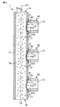
- the filtration filter 40 includes a metal porous film 41 that filters the object to be filtered 11, and a first frame member 42 and a second frame member 43 that sandwich the outer peripheral portion of the metal porous film 41.
- the flow direction of the fluid 12 is parallel to the extending direction of the tube axis A1.
- the metal porous film 41 is disposed in parallel with the extending direction of the tube axis A1.
- an arbitrary cross-sectional shape such as a square or an ellipse may be used.
- Examples of the material of the tubular member 31 include stainless steel, silicon resin, PVDF (Teflon), vinyl chloride, glass, and butadiene-free resin. Furthermore, you may apply
- FIG. 3 is a schematic diagram showing the configuration of the filtration filter 40.
- the metal porous membrane 41 is a membrane that separates the filtration object 11 from the fluid 12.
- the metal porous film 41 is, for example, a circular metal mesh having a first main surface PS1 and a second main surface PS2 facing each other.
- the first main surface PS ⁇ b> 1 is a main surface of the metal porous film 41 located on the flow channel 31 a side of the tubular member 31.
- the second main surface PS2 is a main surface of the metal porous film 41 located on the filtrate outlet 1c side of the tubular member 31.
- Examples of the material of the metal porous film 41 include gold, silver, copper, platinum, nickel, stainless steel, palladium, titanium, cobalt, and alloys thereof.
- the metal porous film 41 has a diameter of, for example, 8 mm.
- the thickness of the metal porous film 41 is, for example, not less than 0.05 ⁇ m and not more than 100 ⁇ m, and preferably not less than 0.1 ⁇ m and not more than 50 ⁇ m.
- the outer shape of the metal porous film 41 may be, for example, a circle, an ellipse, or a polygon.
- the metal porous film 41 includes a film part 41a having a plurality of through holes 41aa and a holding part 41b provided in the outer peripheral part.
- FIG. 4 is an enlarged perspective view of a part of the film part 41 a of the metal porous film 41.
- the X, Y, and Z directions in FIG. 4 indicate the vertical direction, the horizontal direction, and the thickness direction of the metal porous film 41, respectively.
- the film part 41a has a plurality of through holes 41aa penetrating the first main surface PS1 and the second main surface PS2.
- the film part 41a is a plate-like structure (lattice-like structure) in which a plurality of through holes 41aa are arranged in a matrix at regular intervals.
- FIG. 5 is a schematic view of a part of the film part 41a of the metal porous film 41 shown in FIG.
- the plurality of through holes 41aa have a square shape when viewed from the first main surface PS1 side of the film portion 41a of the metal porous film 41, that is, when viewed in the Z direction.
- the plurality of through holes 41aa are provided at equal intervals in two arrangement directions parallel to each side of the square, that is, in the X direction and the Y direction in FIG.
- the through hole 41aa is not limited to a square, and may be, for example, a rectangle, a circle, or an ellipse.
- the arrangement of the holes is not limited to the square lattice arrangement. For example, if the arrangement is a square arrangement, the arrangement may be a rectangular arrangement in which the intervals in the two arrangement directions are not equal, or a triangular lattice arrangement or a quasi-periodic arrangement.
- the shape and size of the through-hole 41aa are appropriately designed according to the size and shape of the filtration object 11 to be filtered.
- the size of the through hole 41aa is, for example, not less than 0.1 ⁇ m and not more than 500 ⁇ m, and not less than 0.1 ⁇ m and not more than 500 ⁇ m.
- the interval between the through holes 41aa is, for example, more than 1 time and less than 10 times, more preferably less than 3 times the opening diameter of the through holes 41aa.
- the opening ratio of the through hole 41aa in the film part 41a of the metal porous film 41 is, for example, 10% or more.
- the holding unit 41b will be described. As shown in FIG. 3, the holding portion 41 b is formed by bending the outer peripheral portion of the metal porous film 41 to the second main surface PS2 side.
- the holding portion 41b is a portion on the outer edge side of the metal porous membrane 41 from a position where the bending starts in the membrane portion 41a.
- the holding portion 41b has a first bent portion 41ba and a second bent portion 41bb.
- the first bent portion 41ba is a portion that bends to the second main surface PS2 side of the film portion 41a.
- the second bent portion 41bb is a portion that is formed on the outer edge side of the metallic porous film 41 with respect to the first bent portion 41ba and bends in the extending direction D1 of the film portion 41a.
- the first bent portion 41ba is bent from the first main surface PS1 to the second main surface PS2 of the film portion 41a.
- the second bent portion 41bb is bent in parallel with the first main surface PS1 and the second main surface PS2 of the film portion 41a. Therefore, in the portion between the first bent portion 41ba and the second bent portion 41bb, the holding portion 41b extends in the direction from the first main surface PS1 of the film portion 41a to the second main surface PS2.
- the holding portion 41b extends in the extending direction D1 of the membrane portion 41a, that is, the first main surface PS1 and the second main surface of the membrane portion 41a. It extends parallel to PS2.
- the extending direction D1 of the film part 41a of the metal porous film 41 includes a direction toward the outer edge side of the metal porous film 41 and a direction opposite to the outer edge of the metal porous film 41.
- the second bent portion 41bb of the holding portion 41b is bent in a direction toward the outer edge side of the metal porous film 41 with respect to the first bent portion 41ba.
- the first bent portion 41ba and the second bent portion 41bb may be, for example, a portion bent in an arc shape or a portion bent at an obtuse angle.
- the first frame member 42 is a frame that sandwiches the holding portion 41 b of the metal porous film 41 with the second frame member 43.
- the first frame member 42 is formed in an annular shape (for example, an annular shape), and is configured to receive the second frame member 43 with the holding portion 41b of the metal porous film 41 interposed therebetween.
- the first frame member 42 is located on the outer edge side of the metallic porous membrane 41 with respect to the boundary between the membrane portion 41a and the holding portion 41b, and contacts the holding portion 41b on the first main surface PS1 side of the metallic porous membrane 41. ing.
- the boundary between the film part 41a and the holding part 41b is a position where the outer peripheral part of the metal porous film 41 starts to bend toward the second main surface PS2.
- the first frame member 42 is located in the extending direction D1 from the bending position of the first bent portion 41ba, and on the first main surface PS1 side of the metal porous film 41, the holding portion 41b is provided. Although it is in contact, it is not in contact with the film part 41a.
- the first frame member 42 is attached to the side wall of the tubular member 31.
- the second frame member 43 is a frame that sandwiches the holding portion 41 b of the metal porous film 41 with the first frame member 42.
- the second frame member 43 is formed in an annular shape (for example, an annular shape).
- a first step portion 43 a that protrudes toward a part of the film portion 41 a of the metal porous film 41 is provided on the inner peripheral portion of the second frame member 43.
- the second frame member 43 is disposed inside the first frame member 42 with the holding portion 41b of the metal porous film 41 interposed therebetween.
- the second frame member 43 is configured such that the first step portion 43 a is fitted inside the first frame member 42. That is, the second frame member 43 is in contact with the holding part 41b and a part of the film part 41a on the second main surface PS2 side of the metal porous film 41.
- the second frame member 43 is connected to the pipe 24.
- the second frame member 43 defines the position of the first main surface PS1 of the film part 41a by pushing the film part 41a from the second main surface PS2 toward the first main surface PS1 by the first step part 43a. be able to.
- Examples of the material of the first frame member 42 and the second frame member 43 include metals such as duralumin and aluminum, and resins such as polyethylene, polystyrene, polypropylene, polycarbonate, polyacetal, polyetherimide, acrylic resin, and polylactic acid. Is mentioned.
- FIG. 6 is an enlarged view of the Z1 portion of the filtration filter 40 of FIG.
- the contact surface 43 aa of the first step portion 43 a of the second frame member 43 in a state where the holding portion 41 b of the metal porous membrane 41 is sandwiched between the first frame member 42 and the second frame member 43.
- the film portion 41a is pushed out from the second main surface PS2 toward the first main surface PS1 by the contact surface 43aa of the first stepped portion 43a.
- the first bent portion 41ba of the holding portion 41b contacts the corner of the first step portion 43a of the second frame member 43, and the direction from the second main surface PS2 of the film portion 41a to the first main surface PS1. Is applied to the holding portion 41b.
- the corner portion of the first step portion 43a of the second frame member 43 supports the holding portion 41b in the first bent portion 41ba in the direction from the second main surface PS2 of the film portion 41a to the first main surface PS1. is doing.
- the holding portion 41b contacts the corner portion of the first frame member 42.
- the corner portion of the first frame member 42 contacts the second bent portion bb, and a force is applied to the holding portion 41b in the direction from the first main surface PS1 to the second main surface PS2 of the film portion 41a.
- the corner portion of the first frame member 42 supports the holding portion 41b in the second bent portion 41bb in the direction from the first main surface PS1 to the second main surface PS2 of the film portion 41a.
- the first bent portion 41ba and the second bent portion 41bb of the holding portion 41b are supported by forces in mutually different directions in the thickness direction D2 of the film portion 41a. Sufficient tension can be applied to hold the porous membrane 41.
- the distance d1 between the first frame member 42 and the second frame member 43 in the extending direction D1 is the distance between the first frame member 42 and the second frame member 43 in the thickness direction D2 of the metal porous film 41. It is designed to be larger than d2. By designing in this way, a gap 44 can be formed between the first frame member 42 and the second frame member 43 in the extending direction D1 of the metal porous film 41.
- the distance d1 is, for example, greater than 1 time and less than 100 times the distance d2.
- the first step 43a protrudes toward a part of the film part 41a, and the film part 41a is pushed out from the second main surface PS2 toward the first main surface PS1 by the contact surface 43aa. ing.
- the film portion 41a contacts the second frame member 43 on the second main surface PS2 side, but does not contact the first frame member 42 on the first main surface side PS1. Since the position of the film part 41a is not limited by the first frame member 42, the holding position of the film part 41a can be freely determined by changing the height h1 of the first step part 43a of the second frame member 43. .
- the height h1 of the first step portion 43a of the second frame member 43 refers to the distance between the first contact surface 43aa of the first step portion 43a of the second frame member 43 and the second contact surface 43ab of the second frame member 43. Means distance.
- the height of the first stepped portion 43a is determined so that the first main surface PS1 of the film portion 41a and the bottom surface 42aa of the first frame member 42 are substantially the same surface.
- the height h1 of the first step 43a is substantially equal to the distance h2 between the third contact surface 42ab of the first frame member 42 and the bottom surface 42aa of the first frame member.
- substantially equal means that the difference between the distance h1 and the distance h2 is within a range of ⁇ 10%.
- the frame member is not limited to an annular shape, and may be any shape such as a square shape or a polygonal shape.
- the 1st frame member 42 and the 2nd frame member 43 are arrange
- the second frame member 43 is in contact with the holding portion 41b on the second main surface PS2 side of the metal porous membrane 41 and a part of the membrane portion 41a.
- the outer peripheral portion of the metal porous film 41 can be firmly held by the first frame member 42 and the second frame member 43. Therefore, the filtration filter 40 suitable for the cross flow filtration method can be provided.
- the second frame member 43 has a first step portion 43a protruding toward a part of the membrane portion 41a. Therefore, the first bent portion 41ba is brought into contact with the first stepped portion 43a of the second frame member 43 in a state where the holding portion 41b of the metal porous film 41 is sandwiched between the first frame member 42 and the second frame member 43.
- the second bent portion 41bb can be brought into contact with the first frame member 42. With such a configuration, the holding portion 41b can be held with tension. Even when a fluid passes through the metal porous membrane 41 and pressure is applied, the first bent portion 41ba and the second bent portion 41bb can be firmly held by the first frame member 32 and the second frame member 43. .
- the contact surface 43aa of the first step portion 43a of the second frame member 43 contacts a part of the film portion 41a so as to push the film portion 41a from the second main surface PS2 toward the first main surface PS1.
- the first frame member 42 is not disposed on the first main surface PS1 side of the film part 41a
- the first hull surface of the film part 41a is determined by determining the height h1 of the first step part 43a.
- the position of the main surface PS1 can be freely defined. That is, the first contact surface 43aa of the first step portion 43a of the second frame member 43 that contacts the first bent portion 41ba and a part of the film portion 41a, and the second frame member 43 that contacts the second bent portion 41bb.
- the position of the first main surface PS1 of the film part 41a can be freely defined.
- the step between the first main surface PS1 of the film part 41a and the bottom surface 42aa of the first frame member 42 can be reduced.
- the height h1 of the first step 43a is a distance h2 between the third contact surface 42ab of the first frame member 42 that contacts the second bent portion 41bb and the bottom surface 42aa of the first frame member. It is set approximately equal. With such a configuration, the first main surface PS1 of the film part 41a and the bottom surface 42aa of the first frame member 42 can be made substantially flush with each other.
- the first frame member 42 and the first step portion of the second frame member 43 in a state where the holding portion 41b of the metal porous membrane 41 is sandwiched between the first frame member 42 and the second frame member 43.
- a gap 44 is formed between the gap 43a.
- the distance of the gap 44 is designed to be larger than the distance of the gap between the first frame member 42 and the second frame member 43 in the thickness direction D2 of the metal porous film 41.
- FIG. 2 shows an example in which the tubular member 31 has a straight cylindrical shape (straight tube shape), but the present invention is not limited to this.
- the tubular member 31 only needs to be configured to allow the fluid 12 to flow along the film part 41a of the metal porous film 41.
- a portion of the tubular member 31 on the fluid introduction port 1a side or fluid discharge port 1b side is configured to bend in a direction intersecting the extending direction of the tube axis A1. May be.
- FIG. 2 shows an example in which one filtration filter 40 is provided for one tubular member 31, but the present invention is not limited to this.
- a plurality of (for example, three) filtration filters 40 may be provided for one tubular member 31.
- the plurality of filtration filters 40 are preferably arranged in the extending direction of the tube axis A1, as shown in FIG.
- the plurality of filtration filters 40 may have different opening diameters of the through holes 41aa of the film portions 41a of the respective metal porous membranes 41. According to this configuration, even if the fluid 12 includes a plurality of filtering objects 11 having different sizes, the filtering objects 11 can be classified.
- FIG. 7 is a view showing a modified filter 40A. As shown in FIG. 7, in the filtration filter 40A, the first bent portion 41ca of the holding portion 41c is bent at an inclination angle ⁇ with respect to the first main surface PS1.
- the first step portions 43b of the first frame member 42a and the second frame member 43 are configured in a shape corresponding to the inclination of the holding portion 41c.
- the surface of the first frame member 42a on the first bent portion 41ca side is formed with an inclination of an angle ⁇ .
- the first stepped portion 43b is formed in a trapezoidal shape that follows the bent shape of the holding portion 41c.
- the second bent portion 41bb has been described as being bent in the extending direction D1 of the film portion 41a, but is not limited thereto.
- the second bent portion 41bb may be supported by the corner portion of the first frame member 42, and may be inclined in an oblique direction with respect to the extending direction D1 of the film portion 41a.
- the second bent portion 41bb of the holding portion 41b is bent in the direction toward the outer edge side of the metal porous film 41
- the present invention is not limited to this.
- the second bent portion 41bb may be bent to the side opposite to the outer edge of the metal porous film 41.
- the first frame member 42 is on the outer edge side of the metallic porous film 20 with respect to the boundary between the film part 41a and the holding part 41b, and on the first main surface PS1 side of the metallic porous film 41.
- the first frame member 42 may be in contact with the holding portion 41b on the upper side (second main surface PS2 side) of the first main surface PS1 of the film portion 41a.
- the 2nd frame member 43 demonstrated the structure which has contacted the holding
- the 2nd frame member 43 may be the structure which contacts only the holding
- the 1st frame member 42 demonstrated the structure formed with the tubular member 31 and a separate member, it is not limited to this.
- the first frame member 42 may be formed integrally with the tubular member 31.
- the 2nd frame member 43 demonstrated the structure formed by the tubular member 31 and a separate member, it is not limited to this.
- the second frame member 43 may be formed integrally with the tubular member 31 on the filtrate discharge port 1c side.
- the 1st frame member 42 and the 2nd frame member 43 may be hold
- the first housing and the second housing may be configured to be fitted to each other by inserting a plurality of convex portions into a plurality of through holes.
- a plurality of convex portions are arranged in a ring shape on the first housing.
- a plurality of through holes are provided in the second housing in an annular shape so as to correspond to the positions of the plurality of convex portions of the first housing.
- the holding portion 41b of the metal porous film 41 may be held between the first frame member 42 and the second frame member 43 by fitting the first housing and the second housing together.
- the first housing and the second housing may be formed integrally with the first frame member 42 and the second frame member 43, respectively.
- FIG. 8 shows a schematic configuration of the filtration filter of the filtration filter 40B of the second embodiment.
- the same or similar components as those in the first embodiment will be described with the same or similar reference numerals.
- descriptions overlapping with those in the first embodiment are omitted.
- the holding part 41d of the metal porous membrane 41 has a third bent part 41dc and a fourth bent part as compared with the filter 40 of the first embodiment.
- the difference is that it has 41dd.
- the second frame member 43 has a second step portion 43c and the first frame member 42b has a third step as compared with the filtration filter 40 of the first embodiment.
- the point which has the part 42ba differs.
- the holding portion 41d includes a third bent portion 41dc and a fourth bent portion 41dd in addition to the first bent portion 41da and the second bent portion 41db.
- the first bent portion 41da and the second bent portion 41db may be formed in the same manner as the first bent portion 41ba and the second bent portion 41bb of the first embodiment.
- the first bent portion 41da is bent from the first main surface PS1 to the second main surface PS2 of the film portion 41a.
- the second bent portion 41db is formed on the outer edge side of the metal porous film 41 with respect to the first bent portion da, and is bent in the extending direction D1 of the film portion 41a.
- the third bent portion 41dc is formed on the outer edge side of the metallic porous film 41 with respect to the second bent portion 41db, and is bent in the direction from the first main surface PS1 to the second main surface PS2 of the film portion 41a.
- the fourth bent portion 41dd is formed on the outer edge side of the metallic porous film 41 with respect to the third bent portion 41dc, and is bent in the extending direction D1 of the film portion 41a.
- the second frame member 43 has a second step portion 43c in addition to the first step portion 43a.
- the second step portion 43c is provided outside the first step portion 43a. That is, the second step portion 43c is provided on the outer edge side of the metal porous film 41 with respect to the first step portion 43a.
- the second stepped portion 43c is formed so as to protrude toward the holding portion 41d on the second main surface PS2 side of the metal porous film 41. Specifically, the second stepped portion 43c protrudes toward the holding portion 41d between the second bent portion 41db and the third bent portion 41dc.
- the first frame member 42b has a third step portion 42ba.
- the third step portion 42ba is formed outside the second step portion 43c of the second frame member 43.
- the third step portion 42ba is formed to protrude toward the holding portion 41d on the first main surface PS1 side of the metal porous film. Specifically, the third stepped portion 42ba protrudes toward the holding portion 41d between the fourth bent portion 41dd and the outer edge of the metal porous film 41.
- the first frame member 42b is formed in an L shape, for example.
- the first bent portion 41da is in contact with the first step portion 43a of the second frame member 43, and the second bent portion 41db is in contact with the first frame member 42b.
- the first bent portion 41da is supported by the corner portion of the first step portion 43a of the second frame member 43, and the second bent portion 41db is supported by the corner portion of the first frame member 42b.
- a force in the direction from the second main surface PS2 of the film portion 41a to the first main surface PS1 is applied by the corner portion of the first step portion 43a of the second frame member 43.
- the second bent portion 41db a force in the direction from the first main surface PS1 to the second main surface PS2 of the film portion 41a is applied by the corner portion of the first frame member 42b.
- the third bent portion 41 dc is in contact with the second step portion 43 c of the second frame member 43. Specifically, the third bent portion 41dc is supported by the corner portion of the second stepped portion 43c, and a force in the direction from the second main surface PS2 to the first main surface PS1 of the film portion 41a is applied. . Therefore, the holding portion 41d is supported in the third bending portion 41dc by the corner portion of the second step portion 43c of the second frame member 43 in the direction from the second main surface PS2 to the first main surface PS1 of the film portion 41a. ing.
- the fourth bent portion 41dd is in contact with the third step portion 43ba of the first frame member 42b. Specifically, the fourth bending portion 41dd is supported by the corner portion of the third step portion 43ba, and a force in the direction from the first main surface PS1 to the second main surface PS2 of the film portion 41a is applied. . Accordingly, the holding portion 41d is supported in the direction from the first main surface PS1 to the second main surface PS2 of the film portion 41a in the fourth bending portion 41dd.
- the contact surface 42ac of the third step part 42ba of the first frame member 42b and the second frame is clamped by the contact surface 43ac of the member 43. That is, the holding portion 41b outside the fourth bent portion 41dd is held by the contact surface 42ac of the first frame member 42 and the contact surface 43ac of the second frame member 43.
- the holding portion 41d having the first bent portion 41da, the second bent portion 41db, the third bent portion 41dc, and the fourth bent portion 41dd is sandwiched between the first frame member 42b and the second frame member 43. is doing.
- the metal porous membrane 41 can be more firmly fixed by the first frame member 42b and the second frame member 43, and a filtration filter 40B suitable for the cross-flow filtration method is provided. be able to.
- the first contact surface 43aa of the first step portion 43a of the second frame member 43 that contacts the first bent portion 41da and a part of the film portion 41a By changing the distance between the second contact surface 43ab of the second frame member 43 that contacts the second bent portion 41db, the position of the first main surface PS1 of the film portion 41a can be freely defined. As a result, the step between the first main surface PS1 of the film part 41a and the bottom surface 42aa of the first frame member 42 can be reduced.
- the holding portion 41d has been described as having four bent portions, but is not limited thereto.
- the holding part 41d may have four or more bent parts.
- the third bending portion 41dc is described as being bent in the direction from the first main surface PS1 to the second main surface PS2 of the film portion 41a.
- the third bent portion 41dc only needs to be supported by the corner of the second stepped portion 43c of the second frame member 43, and is inclined obliquely with respect to the direction from the first main surface PS1 to the second main surface PS2. It may be bent.
- the fourth bent portion 41dd is bent in the extending direction of the film portion 41a has been described, the present invention is not limited to this.
- the first frame member 42b is formed in an L shape.
- the R-shaped portion 42r cannot sufficiently reduce the distance d2 between the first frame member 42b and the second frame member 43 in the thickness direction D2 of the metal porous membrane 41 by contacting the holding portion 41d. Can happen. Thereby, the holding force of the holding part 41d by the first frame member 42b and the second frame member 43 in the thickness direction D2 of the metal porous film 41 is reduced.
- the R-shaped portion 42 r can be a factor that reduces the force for holding the holding portion 41 d by the first frame member 42 b and the second frame member 43 in the thickness direction D2 of the metal porous film 41. Therefore, an annular groove 42c that is recessed downward may be provided at the corner portion of the first frame member 42d as shown in FIG.
- the groove 42c can reduce a decrease in holding force of the holding portion 41d due to the first frame member 42b and the second frame member 43 in the thickness direction D2 of the metal porous film 41.
- the depth and width of the groove 42c are, for example, 0.1 mm.
- the second frame member 43 may be provided with a groove portion at the corner portion similarly to the first frame member 42d.
- the present invention is useful in fields such as chemical material purification and pharmaceuticals.
- it is useful for a filtration apparatus that filters biological material contained in a liquid.
Landscapes
- Chemical & Material Sciences (AREA)
- Chemical Kinetics & Catalysis (AREA)
- Inorganic Chemistry (AREA)
- Health & Medical Sciences (AREA)
- Life Sciences & Earth Sciences (AREA)
- Engineering & Computer Science (AREA)
- Bioinformatics & Cheminformatics (AREA)
- Biotechnology (AREA)
- Wood Science & Technology (AREA)
- Organic Chemistry (AREA)
- Zoology (AREA)
- Genetics & Genomics (AREA)
- Medicinal Chemistry (AREA)
- Biochemistry (AREA)
- General Engineering & Computer Science (AREA)
- General Health & Medical Sciences (AREA)
- Biomedical Technology (AREA)
- Microbiology (AREA)
- Sustainable Development (AREA)
- Separation Using Semi-Permeable Membranes (AREA)
- Physics & Mathematics (AREA)
- Geometry (AREA)
- Filtering Materials (AREA)
- Filtering Of Dispersed Particles In Gases (AREA)
- Filtration Of Liquid (AREA)
Abstract
L'invention fournit un filtre écran dont la structure est adaptée au cas où une filtration à contre courant est effectuée à l'aide d'une membrane poreuse en métal. Le filtre écran de l'invention est équipé : de la membrane poreuse en métal (41) qui possède une partie membrane (41a) filtrant une substance objet de la filtration (11) contenue dans un fluide (12), et d'une partie soutien (41b) agencée sur une périphérie externe ; et d'un premier ainsi que d'un second élément cadre (42, 43) enserrant la partie soutien (41b) de la membrane poreuse en métal (41). La partie soutien (41b) possède des parties courbure (41ba, 41bb) courbées du côté d'une seconde face principale (PS2) s'opposant à une première face principale (PS1) de la partie membrane (41a). Le premier élément cadre (42) vient en contact avec la partie soutien (41b) côté première face principale (PS1) de ladite membrane poreuse en métal (41), et le second élément cadre (43) tout en étant disposé côté interne du premier élément cadre (42), vient en contact avec la partie soutien (41b) côté seconde face principale (PS2) de la membrane poreuse en métal (41).
Priority Applications (3)
| Application Number | Priority Date | Filing Date | Title |
|---|---|---|---|
| JP2017513562A JP6137438B1 (ja) | 2015-12-14 | 2016-10-20 | 濾過フィルタ |
| US15/719,942 US10632427B2 (en) | 2015-12-14 | 2017-09-29 | Filtration filter |
| US16/823,636 US10926229B2 (en) | 2015-12-14 | 2020-03-19 | Filtration filter |
Applications Claiming Priority (2)
| Application Number | Priority Date | Filing Date | Title |
|---|---|---|---|
| JP2015-243476 | 2015-12-14 | ||
| JP2015243476 | 2015-12-14 |
Related Child Applications (1)
| Application Number | Title | Priority Date | Filing Date |
|---|---|---|---|
| US15/719,942 Continuation US10632427B2 (en) | 2015-12-14 | 2017-09-29 | Filtration filter |
Publications (1)
| Publication Number | Publication Date |
|---|---|
| WO2017104259A1 true WO2017104259A1 (fr) | 2017-06-22 |
Family
ID=59056036
Family Applications (1)
| Application Number | Title | Priority Date | Filing Date |
|---|---|---|---|
| PCT/JP2016/081158 Ceased WO2017104259A1 (fr) | 2015-12-14 | 2016-10-20 | Filtre écran |
Country Status (3)
| Country | Link |
|---|---|
| US (2) | US10632427B2 (fr) |
| JP (1) | JP6332519B2 (fr) |
| WO (1) | WO2017104259A1 (fr) |
Cited By (4)
| Publication number | Priority date | Publication date | Assignee | Title |
|---|---|---|---|---|
| WO2018212096A1 (fr) * | 2017-05-19 | 2018-11-22 | 株式会社村田製作所 | Dispositif de filtration |
| WO2019009044A1 (fr) * | 2017-07-03 | 2019-01-10 | 株式会社村田製作所 | Dispositif de concentration |
| WO2020039677A1 (fr) * | 2018-08-23 | 2020-02-27 | 株式会社村田製作所 | Dispositif de filtration et procédé de filtration |
| CN117919984A (zh) * | 2024-03-21 | 2024-04-26 | 山西恒泰佳源生物科技有限公司 | 一种复合碳源生产用原料配比装置 |
Families Citing this family (2)
| Publication number | Priority date | Publication date | Assignee | Title |
|---|---|---|---|---|
| JP3047622B2 (ja) | 1992-04-28 | 2000-05-29 | 信越半導体株式会社 | 過酸化水素含有排水の処理方法及びその装置 |
| JP7797222B2 (ja) * | 2022-01-25 | 2026-01-13 | 日立グローバルライフソリューションズ株式会社 | 洗濯機 |
Citations (12)
| Publication number | Priority date | Publication date | Assignee | Title |
|---|---|---|---|---|
| JPS5631825U (fr) * | 1979-08-20 | 1981-03-28 | ||
| JPS59154322U (ja) * | 1983-04-04 | 1984-10-16 | 株式会社クボタ | 流体吸入用ホ−スにおける異物除去用網状体取付構造 |
| JPS6086433U (ja) * | 1983-11-17 | 1985-06-14 | 西武機材株式会社 | 塵埃補集具 |
| JPS62123737U (fr) * | 1986-01-27 | 1987-08-06 | ||
| JPS63242303A (ja) * | 1987-03-30 | 1988-10-07 | Kurita Water Ind Ltd | 被張設物の固定装置 |
| JPH0225006U (fr) * | 1988-08-05 | 1990-02-19 | ||
| JP2000167318A (ja) * | 1998-12-01 | 2000-06-20 | Ultra Clean Technology Kaihatsu Kenkyusho:Kk | ガスケットフィルタ |
| JP2002537523A (ja) * | 1999-02-26 | 2002-11-05 | ドナルドソン カンパニー,インコーポレイティド | 枠構造体に挿入される濾過エレメントとその使用方法 |
| JP2003093817A (ja) * | 2001-09-27 | 2003-04-02 | Noritz Corp | フィルタ |
| JP2006501450A (ja) * | 2002-10-02 | 2006-01-12 | ジーシックス サイエンス コーポレーション | 所望量の物質を捕捉するためのフィルターデバイスおよびその使用方法 |
| DE102006009623A1 (de) * | 2006-03-02 | 2007-09-06 | Frank Sommer | Verfahren zum Herstellen eines Membranfilterelements |
| WO2015151762A1 (fr) * | 2014-03-31 | 2015-10-08 | 株式会社クボタ | Procede de fabrication d'un element membranaire plat et element membranaire plat |
Family Cites Families (5)
| Publication number | Priority date | Publication date | Assignee | Title |
|---|---|---|---|---|
| JPS57167712A (en) * | 1981-04-10 | 1982-10-15 | Hitachi Ltd | Strainer |
| JPS6443305A (en) * | 1987-08-10 | 1989-02-15 | Fuji Photo Film Co Ltd | Cross flow type filtration process |
| JPH0380921A (ja) * | 1989-08-24 | 1991-04-05 | Shinko Pantec Co Ltd | 膜濾過装置の運転方法 |
| JP2012217872A (ja) * | 2011-04-04 | 2012-11-12 | Shimadzu Corp | ろ過装置 |
| JP6322882B2 (ja) | 2012-03-30 | 2018-05-16 | 栗田工業株式会社 | 水系におけるオンライン測定用前処理装置、および該オンライン測定用前処理装置を用いたオンライン測定装置、並びにオンライン測定における前処理方法、および該前処理方法を用いたオンライン測定方法 |
-
2016
- 2016-10-20 WO PCT/JP2016/081158 patent/WO2017104259A1/fr not_active Ceased
-
2017
- 2017-04-25 JP JP2017086582A patent/JP6332519B2/ja active Active
- 2017-09-29 US US15/719,942 patent/US10632427B2/en active Active
-
2020
- 2020-03-19 US US16/823,636 patent/US10926229B2/en active Active
Patent Citations (12)
| Publication number | Priority date | Publication date | Assignee | Title |
|---|---|---|---|---|
| JPS5631825U (fr) * | 1979-08-20 | 1981-03-28 | ||
| JPS59154322U (ja) * | 1983-04-04 | 1984-10-16 | 株式会社クボタ | 流体吸入用ホ−スにおける異物除去用網状体取付構造 |
| JPS6086433U (ja) * | 1983-11-17 | 1985-06-14 | 西武機材株式会社 | 塵埃補集具 |
| JPS62123737U (fr) * | 1986-01-27 | 1987-08-06 | ||
| JPS63242303A (ja) * | 1987-03-30 | 1988-10-07 | Kurita Water Ind Ltd | 被張設物の固定装置 |
| JPH0225006U (fr) * | 1988-08-05 | 1990-02-19 | ||
| JP2000167318A (ja) * | 1998-12-01 | 2000-06-20 | Ultra Clean Technology Kaihatsu Kenkyusho:Kk | ガスケットフィルタ |
| JP2002537523A (ja) * | 1999-02-26 | 2002-11-05 | ドナルドソン カンパニー,インコーポレイティド | 枠構造体に挿入される濾過エレメントとその使用方法 |
| JP2003093817A (ja) * | 2001-09-27 | 2003-04-02 | Noritz Corp | フィルタ |
| JP2006501450A (ja) * | 2002-10-02 | 2006-01-12 | ジーシックス サイエンス コーポレーション | 所望量の物質を捕捉するためのフィルターデバイスおよびその使用方法 |
| DE102006009623A1 (de) * | 2006-03-02 | 2007-09-06 | Frank Sommer | Verfahren zum Herstellen eines Membranfilterelements |
| WO2015151762A1 (fr) * | 2014-03-31 | 2015-10-08 | 株式会社クボタ | Procede de fabrication d'un element membranaire plat et element membranaire plat |
Cited By (11)
| Publication number | Priority date | Publication date | Assignee | Title |
|---|---|---|---|---|
| WO2018212096A1 (fr) * | 2017-05-19 | 2018-11-22 | 株式会社村田製作所 | Dispositif de filtration |
| WO2019009044A1 (fr) * | 2017-07-03 | 2019-01-10 | 株式会社村田製作所 | Dispositif de concentration |
| CN110831684A (zh) * | 2017-07-03 | 2020-02-21 | 株式会社村田制作所 | 浓缩装置 |
| JPWO2019009044A1 (ja) * | 2017-07-03 | 2020-03-26 | 株式会社村田製作所 | 濃縮装置 |
| US11498032B2 (en) | 2017-07-03 | 2022-11-15 | Murata Manufacturing Co., Ltd. | Concentration apparatus |
| CN110831684B (zh) * | 2017-07-03 | 2026-03-27 | 株式会社村田制作所 | 浓缩装置 |
| WO2020039677A1 (fr) * | 2018-08-23 | 2020-02-27 | 株式会社村田製作所 | Dispositif de filtration et procédé de filtration |
| JPWO2020039677A1 (ja) * | 2018-08-23 | 2021-04-30 | 株式会社村田製作所 | 濾過装置及び濾過方法 |
| JP7192867B2 (ja) | 2018-08-23 | 2022-12-20 | 株式会社村田製作所 | 濾過装置及び濾過方法 |
| CN117919984A (zh) * | 2024-03-21 | 2024-04-26 | 山西恒泰佳源生物科技有限公司 | 一种复合碳源生产用原料配比装置 |
| CN117919984B (zh) * | 2024-03-21 | 2024-06-07 | 山西恒泰佳源生物科技有限公司 | 一种复合碳源生产用原料配比装置 |
Also Published As
| Publication number | Publication date |
|---|---|
| JP6332519B2 (ja) | 2018-05-30 |
| US20200215497A1 (en) | 2020-07-09 |
| JP2017159300A (ja) | 2017-09-14 |
| US10926229B2 (en) | 2021-02-23 |
| US10632427B2 (en) | 2020-04-28 |
| US20180021737A1 (en) | 2018-01-25 |
Similar Documents
| Publication | Publication Date | Title |
|---|---|---|
| JP6332519B2 (ja) | 濾過装置 | |
| JP6137438B1 (ja) | 濾過フィルタ | |
| JP6394804B2 (ja) | 濾過フィルター | |
| JP6645576B2 (ja) | 濾過フィルタデバイス | |
| Abdallah et al. | Protein crystallization in an actuated microfluidic nanowell device | |
| WO2017022484A1 (fr) | Dispositif de filtration à filtre | |
| WO2017104261A1 (fr) | Dispositif de filtration | |
| WO2017141609A1 (fr) | Filtre de filtration et dispositif de filtre de filtration | |
| US11529579B2 (en) | Filtration device | |
| JP6323632B2 (ja) | 濾過フィルタデバイス | |
| JP7294432B2 (ja) | 濾過回収装置 | |
| US20200346144A1 (en) | Filtration filter and filtration device | |
| WO2022123953A1 (fr) | Dispositif de filtration, système de filtration, et procédé de filtration | |
| Maity et al. | Self-organized implanting of micro/nanofiltration membranes in advanced flow μ-reactors | |
| JP5458581B2 (ja) | 液体クロマトグラフィ装置 | |
| WO2018212096A1 (fr) | Dispositif de filtration | |
| JP2016214154A (ja) | 濾過容器、濾過装置、及び濾過方法 | |
| US20240066440A1 (en) | Filter device | |
| WO2017104260A1 (fr) | Dispositif de filtration | |
| CN115297941B (zh) | 过滤器以及过滤设备 | |
| JP6192007B2 (ja) | マイクロデバイス及びバイオアッセイシステム | |
| JPWO2018042943A1 (ja) | サンプリングフィルター、サンプリング装置およびそれを用いたサンプリング方法 | |
| JP2024031809A (ja) | フィルタデバイス | |
| JPWO2021186825A5 (fr) |
Legal Events
| Date | Code | Title | Description |
|---|---|---|---|
| ENP | Entry into the national phase |
Ref document number: 2017513562 Country of ref document: JP Kind code of ref document: A |
|
| 121 | Ep: the epo has been informed by wipo that ep was designated in this application |
Ref document number: 16875244 Country of ref document: EP Kind code of ref document: A1 |
|
| NENP | Non-entry into the national phase |
Ref country code: DE |
|
| 122 | Ep: pct application non-entry in european phase |
Ref document number: 16875244 Country of ref document: EP Kind code of ref document: A1 |