WO2017104301A1 - 燃料電池システム、及び燃料電池システムの制御方法 - Google Patents
燃料電池システム、及び燃料電池システムの制御方法 Download PDFInfo
- Publication number
- WO2017104301A1 WO2017104301A1 PCT/JP2016/083122 JP2016083122W WO2017104301A1 WO 2017104301 A1 WO2017104301 A1 WO 2017104301A1 JP 2016083122 W JP2016083122 W JP 2016083122W WO 2017104301 A1 WO2017104301 A1 WO 2017104301A1
- Authority
- WO
- WIPO (PCT)
- Prior art keywords
- fuel cell
- gas
- fuel
- cell system
- combustor
- Prior art date
- Legal status (The legal status is an assumption and is not a legal conclusion. Google has not performed a legal analysis and makes no representation as to the accuracy of the status listed.)
- Ceased
Links
Images




Classifications
-
- H—ELECTRICITY
- H01—ELECTRIC ELEMENTS
- H01M—PROCESSES OR MEANS, e.g. BATTERIES, FOR THE DIRECT CONVERSION OF CHEMICAL ENERGY INTO ELECTRICAL ENERGY
- H01M8/00—Fuel cells; Manufacture thereof
- H01M8/04—Auxiliary arrangements, e.g. for control of pressure or for circulation of fluids
- H01M8/04298—Processes for controlling fuel cells or fuel cell systems
- H01M8/04694—Processes for controlling fuel cells or fuel cell systems characterised by variables to be controlled
- H01M8/04746—Pressure; Flow
- H01M8/04761—Pressure; Flow of fuel cell exhausts
-
- H—ELECTRICITY
- H01—ELECTRIC ELEMENTS
- H01M—PROCESSES OR MEANS, e.g. BATTERIES, FOR THE DIRECT CONVERSION OF CHEMICAL ENERGY INTO ELECTRICAL ENERGY
- H01M8/00—Fuel cells; Manufacture thereof
- H01M8/04—Auxiliary arrangements, e.g. for control of pressure or for circulation of fluids
- H01M8/04007—Auxiliary arrangements, e.g. for control of pressure or for circulation of fluids related to heat exchange
- H01M8/04014—Heat exchange using gaseous fluids; Heat exchange by combustion of reactants
- H01M8/04022—Heating by combustion
-
- H—ELECTRICITY
- H01—ELECTRIC ELEMENTS
- H01M—PROCESSES OR MEANS, e.g. BATTERIES, FOR THE DIRECT CONVERSION OF CHEMICAL ENERGY INTO ELECTRICAL ENERGY
- H01M8/00—Fuel cells; Manufacture thereof
- H01M8/04—Auxiliary arrangements, e.g. for control of pressure or for circulation of fluids
- H01M8/04082—Arrangements for control of reactant parameters, e.g. pressure or concentration
- H01M8/04201—Reactant storage and supply, e.g. means for feeding, pipes
-
- H—ELECTRICITY
- H01—ELECTRIC ELEMENTS
- H01M—PROCESSES OR MEANS, e.g. BATTERIES, FOR THE DIRECT CONVERSION OF CHEMICAL ENERGY INTO ELECTRICAL ENERGY
- H01M8/00—Fuel cells; Manufacture thereof
- H01M8/04—Auxiliary arrangements, e.g. for control of pressure or for circulation of fluids
- H01M8/04223—Auxiliary arrangements, e.g. for control of pressure or for circulation of fluids during start-up or shut-down; Depolarisation or activation, e.g. purging; Means for short-circuiting defective fuel cells
- H01M8/04228—Auxiliary arrangements, e.g. for control of pressure or for circulation of fluids during start-up or shut-down; Depolarisation or activation, e.g. purging; Means for short-circuiting defective fuel cells during shut-down
-
- H—ELECTRICITY
- H01—ELECTRIC ELEMENTS
- H01M—PROCESSES OR MEANS, e.g. BATTERIES, FOR THE DIRECT CONVERSION OF CHEMICAL ENERGY INTO ELECTRICAL ENERGY
- H01M8/00—Fuel cells; Manufacture thereof
- H01M8/04—Auxiliary arrangements, e.g. for control of pressure or for circulation of fluids
- H01M8/04223—Auxiliary arrangements, e.g. for control of pressure or for circulation of fluids during start-up or shut-down; Depolarisation or activation, e.g. purging; Means for short-circuiting defective fuel cells
- H01M8/04231—Purging of the reactants
-
- H—ELECTRICITY
- H01—ELECTRIC ELEMENTS
- H01M—PROCESSES OR MEANS, e.g. BATTERIES, FOR THE DIRECT CONVERSION OF CHEMICAL ENERGY INTO ELECTRICAL ENERGY
- H01M8/00—Fuel cells; Manufacture thereof
- H01M8/04—Auxiliary arrangements, e.g. for control of pressure or for circulation of fluids
- H01M8/04298—Processes for controlling fuel cells or fuel cell systems
- H01M8/043—Processes for controlling fuel cells or fuel cell systems applied during specific periods
- H01M8/04303—Processes for controlling fuel cells or fuel cell systems applied during specific periods applied during shut-down
-
- H—ELECTRICITY
- H01—ELECTRIC ELEMENTS
- H01M—PROCESSES OR MEANS, e.g. BATTERIES, FOR THE DIRECT CONVERSION OF CHEMICAL ENERGY INTO ELECTRICAL ENERGY
- H01M8/00—Fuel cells; Manufacture thereof
- H01M8/04—Auxiliary arrangements, e.g. for control of pressure or for circulation of fluids
- H01M8/04298—Processes for controlling fuel cells or fuel cell systems
- H01M8/04313—Processes for controlling fuel cells or fuel cell systems characterised by the detection or assessment of variables; characterised by the detection or assessment of failure or abnormal function
- H01M8/0432—Temperature; Ambient temperature
- H01M8/04328—Temperature; Ambient temperature of anode reactants at the inlet or inside the fuel cell
-
- H—ELECTRICITY
- H01—ELECTRIC ELEMENTS
- H01M—PROCESSES OR MEANS, e.g. BATTERIES, FOR THE DIRECT CONVERSION OF CHEMICAL ENERGY INTO ELECTRICAL ENERGY
- H01M8/00—Fuel cells; Manufacture thereof
- H01M8/04—Auxiliary arrangements, e.g. for control of pressure or for circulation of fluids
- H01M8/04298—Processes for controlling fuel cells or fuel cell systems
- H01M8/04313—Processes for controlling fuel cells or fuel cell systems characterised by the detection or assessment of variables; characterised by the detection or assessment of failure or abnormal function
- H01M8/0432—Temperature; Ambient temperature
- H01M8/04365—Temperature; Ambient temperature of other components of a fuel cell or fuel cell stacks
-
- H—ELECTRICITY
- H01—ELECTRIC ELEMENTS
- H01M—PROCESSES OR MEANS, e.g. BATTERIES, FOR THE DIRECT CONVERSION OF CHEMICAL ENERGY INTO ELECTRICAL ENERGY
- H01M8/00—Fuel cells; Manufacture thereof
- H01M8/04—Auxiliary arrangements, e.g. for control of pressure or for circulation of fluids
- H01M8/04298—Processes for controlling fuel cells or fuel cell systems
- H01M8/04313—Processes for controlling fuel cells or fuel cell systems characterised by the detection or assessment of variables; characterised by the detection or assessment of failure or abnormal function
- H01M8/0438—Pressure; Ambient pressure; Flow
- H01M8/04388—Pressure; Ambient pressure; Flow of anode reactants at the inlet or inside the fuel cell
-
- H—ELECTRICITY
- H01—ELECTRIC ELEMENTS
- H01M—PROCESSES OR MEANS, e.g. BATTERIES, FOR THE DIRECT CONVERSION OF CHEMICAL ENERGY INTO ELECTRICAL ENERGY
- H01M8/00—Fuel cells; Manufacture thereof
- H01M8/04—Auxiliary arrangements, e.g. for control of pressure or for circulation of fluids
- H01M8/04298—Processes for controlling fuel cells or fuel cell systems
- H01M8/04313—Processes for controlling fuel cells or fuel cell systems characterised by the detection or assessment of variables; characterised by the detection or assessment of failure or abnormal function
- H01M8/0438—Pressure; Ambient pressure; Flow
- H01M8/04432—Pressure differences, e.g. between anode and cathode
-
- H—ELECTRICITY
- H01—ELECTRIC ELEMENTS
- H01M—PROCESSES OR MEANS, e.g. BATTERIES, FOR THE DIRECT CONVERSION OF CHEMICAL ENERGY INTO ELECTRICAL ENERGY
- H01M8/00—Fuel cells; Manufacture thereof
- H01M8/04—Auxiliary arrangements, e.g. for control of pressure or for circulation of fluids
- H01M8/04298—Processes for controlling fuel cells or fuel cell systems
- H01M8/04313—Processes for controlling fuel cells or fuel cell systems characterised by the detection or assessment of variables; characterised by the detection or assessment of failure or abnormal function
- H01M8/0444—Concentration; Density
- H01M8/04447—Concentration; Density of anode reactants at the inlet or inside the fuel cell
-
- H—ELECTRICITY
- H01—ELECTRIC ELEMENTS
- H01M—PROCESSES OR MEANS, e.g. BATTERIES, FOR THE DIRECT CONVERSION OF CHEMICAL ENERGY INTO ELECTRICAL ENERGY
- H01M8/00—Fuel cells; Manufacture thereof
- H01M8/04—Auxiliary arrangements, e.g. for control of pressure or for circulation of fluids
- H01M8/04298—Processes for controlling fuel cells or fuel cell systems
- H01M8/04694—Processes for controlling fuel cells or fuel cell systems characterised by variables to be controlled
- H01M8/04701—Temperature
- H01M8/04738—Temperature of auxiliary devices, e.g. reformer, compressor, burner
-
- H—ELECTRICITY
- H01—ELECTRIC ELEMENTS
- H01M—PROCESSES OR MEANS, e.g. BATTERIES, FOR THE DIRECT CONVERSION OF CHEMICAL ENERGY INTO ELECTRICAL ENERGY
- H01M8/00—Fuel cells; Manufacture thereof
- H01M8/04—Auxiliary arrangements, e.g. for control of pressure or for circulation of fluids
- H01M8/04298—Processes for controlling fuel cells or fuel cell systems
- H01M8/04694—Processes for controlling fuel cells or fuel cell systems characterised by variables to be controlled
- H01M8/04746—Pressure; Flow
- H01M8/04776—Pressure; Flow at auxiliary devices, e.g. reformer, compressor, burner
-
- H—ELECTRICITY
- H01—ELECTRIC ELEMENTS
- H01M—PROCESSES OR MEANS, e.g. BATTERIES, FOR THE DIRECT CONVERSION OF CHEMICAL ENERGY INTO ELECTRICAL ENERGY
- H01M8/00—Fuel cells; Manufacture thereof
- H01M8/06—Combination of fuel cells with means for production of reactants or for treatment of residues
- H01M8/0606—Combination of fuel cells with means for production of reactants or for treatment of residues with means for production of gaseous reactants
- H01M8/0612—Combination of fuel cells with means for production of reactants or for treatment of residues with means for production of gaseous reactants from carbon-containing material
- H01M8/0618—Reforming processes, e.g. autothermal, partial oxidation or steam reforming
-
- H—ELECTRICITY
- H01—ELECTRIC ELEMENTS
- H01M—PROCESSES OR MEANS, e.g. BATTERIES, FOR THE DIRECT CONVERSION OF CHEMICAL ENERGY INTO ELECTRICAL ENERGY
- H01M8/00—Fuel cells; Manufacture thereof
- H01M8/06—Combination of fuel cells with means for production of reactants or for treatment of residues
- H01M8/0662—Treatment of gaseous reactants or gaseous residues, e.g. cleaning
-
- H—ELECTRICITY
- H01—ELECTRIC ELEMENTS
- H01M—PROCESSES OR MEANS, e.g. BATTERIES, FOR THE DIRECT CONVERSION OF CHEMICAL ENERGY INTO ELECTRICAL ENERGY
- H01M8/00—Fuel cells; Manufacture thereof
- H01M8/10—Fuel cells with solid electrolytes
- H01M8/12—Fuel cells with solid electrolytes operating at high temperature, e.g. with stabilised ZrO2 electrolyte
- H01M2008/1293—Fuel cells with solid oxide electrolytes
-
- Y—GENERAL TAGGING OF NEW TECHNOLOGICAL DEVELOPMENTS; GENERAL TAGGING OF CROSS-SECTIONAL TECHNOLOGIES SPANNING OVER SEVERAL SECTIONS OF THE IPC; TECHNICAL SUBJECTS COVERED BY FORMER USPC CROSS-REFERENCE ART COLLECTIONS [XRACs] AND DIGESTS
- Y02—TECHNOLOGIES OR APPLICATIONS FOR MITIGATION OR ADAPTATION AGAINST CLIMATE CHANGE
- Y02E—REDUCTION OF GREENHOUSE GAS [GHG] EMISSIONS, RELATED TO ENERGY GENERATION, TRANSMISSION OR DISTRIBUTION
- Y02E60/00—Enabling technologies; Technologies with a potential or indirect contribution to GHG emissions mitigation
- Y02E60/30—Hydrogen technology
- Y02E60/50—Fuel cells
Definitions
- the present invention relates to a fuel cell system that burns and discharges fuel gas discharged from a fuel cell, and a control method for the fuel cell system.
- US Patent Application Publication No. 2014/0113162 describes that when the fuel cell system is stopped, the anode flow path is kept in a reducing atmosphere in order to prevent oxidation of the anode of the fuel cell.
- An object of the present invention is to provide a fuel cell system and a control method for the fuel cell system that suppress the discharge of unburned fuel gas from the fuel cell system.
- a fuel cell system includes an oxidant supply device that supplies an oxidant gas to the fuel cell, a fuel supply device that supplies the fuel gas to the fuel cell, and the fuel cell that is discharged from the fuel cell. And a combustor that introduces a fuel off-gas and an oxidant off-gas and burns and discharges the mixed gas.
- the fuel cell system control method includes a power generation control step of supplying fuel gas and oxidant gas to the fuel cell to generate power, and when the fuel cell system is stopped, And a stop control step of stopping the supply of fuel gas and supplying an oxidant gas to the combustor based on the amount of unburned fuel gas in the fuel cell system.
- air having a flow rate corresponding to the amount of unburned fuel gas that remains in the fuel cell system after the supply of fuel gas is stopped is supplied to the combustor. It is possible to suppress the occurrence of incomplete combustion of unburned fuel gas due to the above. Therefore, the amount of unburned fuel gas discharged from the fuel cell system can be suppressed.
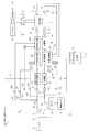
- FIG. 1 is a block diagram showing the main configuration of the fuel cell system according to the first embodiment of the present invention.
- FIG. 2 is a flowchart showing an example of a method for stopping the fuel cell system according to the first embodiment.
- FIG. 3 is a flowchart showing an example of a fuel cell system stop method according to the second embodiment of the present invention.
- FIG. 4 is a flowchart showing another example of the method for stopping the fuel cell system.
- FIG. 5 is a time chart when the oxidant gas is supplied to the fuel passage based on the temperature of the fuel cell when the fuel cell system is stopped.
- FIG. 6 is a flowchart showing another example of the method for stopping the fuel cell system.
- FIG. 1 is a block diagram showing the main configuration of the fuel cell system according to the first embodiment of the present invention.
- FIG. 2 is a flowchart showing an example of a method for stopping the fuel cell system according to the first embodiment.
- FIG. 3 is a flowchart showing an example of a fuel cell
- FIG. 7 is a time chart when the oxidant gas is supplied to the fuel passage based on the pressure of the fuel passage when the fuel cell system is stopped.
- FIG. 8 is a block diagram showing the main configuration of the fuel cell system according to the third embodiment of the present invention.
- FIG. 9 is a flowchart showing an example of a starting method of the fuel cell system.
- FIG. 10 is a flowchart showing an example of a method for stopping the fuel cell system.
- FIG. 1 is a block diagram showing a main configuration of a fuel cell system 10 according to the first embodiment of the present invention.
- the fuel cell system 10 of this embodiment is a solid oxide fuel cell system.
- the fuel cell system 10 includes a fuel supply system 2 that supplies anode gas (fuel gas) to the fuel cell stack 1 and an oxidant supply system 3 that supplies cathode gas (oxidant gas) to the fuel cell stack 1.
- the fuel cell system 10 includes an exhaust system 4 that discharges anode off-gas (fuel off-gas) and cathode off-gas (oxidant off-gas) discharged from the fuel cell stack 1 to the outside, and takes out electric power from the fuel cell stack 1 to load.
- a drive system 5 that secures driving force and a control unit 6 that controls the overall operation of the fuel cell system 10 are provided.
- the fuel cell stack 1 is a solid oxide fuel cell (SOFC).
- SOFC solid oxide fuel cell
- the fuel cell stack 1 is formed by stacking a plurality of cells configured by sandwiching an electrolyte layer formed of a solid oxide such as ceramic between an anode electrode (fuel electrode) and a cathode electrode (air electrode).
- An anode gas reformed by the reformer 26 is supplied to the anode electrode of the fuel cell stack 1, and air containing oxygen as a cathode gas is supplied to the cathode electrode of the fuel cell stack 1.
- electric power is generated by reacting hydrogen contained in the anode gas and oxygen contained in the cathode gas, and the anode off-gas and cathode off-gas generated after the reaction are discharged to the outside. .
- the bipolar manifold formed in the fuel cell stack 1 has an anode gas supply passage 22 and an anode gas discharge passage 29 that constitute a passage through which the anode gas flows, and a cathode gas supply passage that constitutes a passage through which the cathode gas flows. 33 and the cathode gas discharge passage 39 are connected.
- the anode gas supply passage 22 is a route for supplying anode gas to the fuel cell stack 1
- the anode gas discharge passage 29 is a route for introducing the anode off gas discharged from the fuel cell stack 1 into the exhaust combustor 40.
- the cathode gas supply passage 33 is a passage for supplying a cathode gas to the fuel cell stack 1
- the cathode gas discharge passage 39 is an exhaust passage for introducing the cathode off gas discharged from the fuel cell stack 1 into the exhaust combustor 40. It is.
- the fuel supply system 2 is a fuel supply device that supplies anode gas to the fuel cell stack 1.
- the fuel supply system 2 includes a fuel tank 20, a pump 21, an anode gas supply passage 22, a fuel supply valve 23, an evaporator 24, a heat exchanger 25, and a reformer 26.
- the fuel tank 20 stores liquid containing fuel.
- reforming fuel made of a liquid obtained by mixing ethanol and water is stored.
- the pump 21 sucks the reforming fuel and supplies the reforming fuel to the fuel supply system 2 at a constant pressure.
- the anode gas supply passage 22 is a fuel passage through which the anode gas passes through the fuel cell stack 1.
- the anode gas supply passage 22 is provided with a fuel supply valve 23, an evaporator 24, a heat exchanger 25, and a reformer 26.
- the fuel supply valve 23 supplies the reforming fuel supplied from the pump 21 to the injection nozzle 23a and injects it into the evaporator 24 through the injection nozzle 23a.
- the evaporator 24 vaporizes the reforming fuel using the heat of the exhaust gas exhausted from the exhaust combustor 40.
- the heat exchanger 25 is supplied with heat from the exhaust combustor 40, and further heats the vaporized reforming fuel for reforming in the reformer 26.
- the reformer 26 reforms the reforming fuel into an anode gas containing hydrogen by a catalytic reaction and supplies the reformed fuel to the anode electrode of the fuel cell stack 1.
- steam reforming is performed to reform the fuel using steam.
- at least 2 mol of steam (S) is required for 1 mol of carbon (C) contained in the reforming fuel.
- partial oxidation reforming is performed in which fuel is reformed using air instead of steam.
- a pressure sensor 61 and a temperature sensor 62 are provided in the anode gas supply passage 22 located between the reformer 26 and the fuel cell stack 1.
- the pressure sensor 61 detects the pressure of the anode gas supplied to the fuel cell stack 1.
- the pressure sensor 61 of this embodiment detects the pressure in the anode gas supply passage 22.
- the detection value of the pressure sensor 61 is hereinafter referred to as “stack inlet anode pressure”.
- the stack inlet anode pressure detected by the pressure sensor 61 is output to the controller 6.
- the temperature sensor 62 detects the temperature of the anode gas supplied to the fuel cell stack 1.
- the detection value of the temperature sensor 62 is hereinafter referred to as “stack inlet temperature”.
- the stack inlet temperature detected by the temperature sensor 62 is output to the control unit 6.
- a temperature sensor 63 is also provided for the anode gas discharge passage 29 located between the fuel cell stack 1 and the exhaust combustor 40.
- the temperature sensor 63 detects the temperature of the anode off gas discharged from the fuel cell stack 1.
- the detection value of the temperature sensor 63 is referred to as “stack outlet temperature”.
- the stack outlet temperature detected by the temperature sensor 63 is output to the control unit 6.
- the oxidant supply system 3 is an oxidant supply device that supplies an oxidant gas to the fuel cell stack 1.
- the oxidant supply system 3 includes a filter 30, an air intake passage 31, a compressor 32, a cathode gas supply passage 33, a cathode flow rate control valve 34, a heating device 35, a reforming temperature control air passage 311, a combustion And an air control valve 312. Further, the oxidant supply system 3 includes an oxidation reforming passage 331 and an anode air supply valve 341.
- the filter 30 removes foreign matter from the outside air and introduces the outside air into the fuel cell system 10.
- the air suction passage 31 is a passage through which the air from which foreign matter has been removed by the filter 30 passes through the compressor 32.
- One end of the air intake passage 31 is connected to the filter 30, and the other end is connected to the intake port of the compressor 32.
- the compressor 32 is an actuator that supplies a cathode gas to the fuel cell stack 1.
- the compressor 32 takes in outside air through the filter 30 and supplies air to the fuel cell stack 1 and the like.
- a compressor that pumps air is used as the actuator that supplies the cathode gas to the fuel cell stack 1, but any device that can supply the cathode gas to the fuel cell stack 1 may be used.
- An actuator such as a pump may be used.
- the cathode flow rate control valve 34 is a control valve that controls the flow rate of the cathode gas supplied to the fuel cell stack 1.
- the cathode flow rate control valve 34 is constituted by an electromagnetic valve.
- the opening degree of the cathode flow rate control valve 34 can be changed in stages, and is controlled by the control unit 6.
- the heating device 35 is a device that heats the cathode gas supplied to the fuel cell stack 1 so that the temperature of the cathode gas becomes a temperature suitable for power generation of the fuel cell stack 1.
- the heating device 35 is a heat exchanger that exchanges heat between the supply gas to the cathode of the fuel cell stack 1 and the exhaust gas from the fuel cell stack 1, or combustion that heats the supply gas by burning the fuel gas And a combustor that heats the supply gas using heat of the catalytic reaction.
- a temperature sensor 66 is provided in the cathode gas supply passage 33 located between the heating device 35 and the fuel cell stack 1.
- the temperature sensor 66 detects the temperature of the cathode gas supplied to the fuel cell stack 1.
- the detection value of the temperature sensor 66 is hereinafter referred to as “cathode inlet temperature”.
- the cathode inlet temperature detected by the temperature sensor 66 is output to the control unit 6.
- the reforming temperature control air passage 311 is an air passage provided for adjusting the temperature of the fuel gas supplied to the reformer 26 to a temperature necessary for the reforming reaction.
- the reforming temperature control air passage 311 is a bypass passage branched from the air intake passage 31 and connected to the exhaust combustor 40.
- the reforming temperature control air passage 311 is connected to the exhaust combustor 40, but may be joined to the cathode gas discharge passage 39.
- the combustor air control valve 312 is a control valve for supplying or blocking air to the exhaust combustor 40.
- the combustor air control valve 312 is controlled to be opened and closed by the control unit 6. Since the exhaust combustor 40 burns and heats fuel gas, oxygen is required. When the fuel cell system 10 is started up or during normal power generation, oxygen in the cathode offgas may be insufficient. In such a case, it becomes difficult to sufficiently burn the anode off-gas, so the combustion air control valve 312 is opened to supply the combustion promoting gas (oxygen) to the exhaust combustor 40. Thereby, the unburned fuel gas in the anode off-gas can be appropriately combusted by the exhaust combustor 40 when the fuel cell system 10 is started and during normal power generation.
- the oxidation reforming passage 331 is provided to replenish air to the reformer 26 as a substitute for steam when the steam necessary for the steam reforming reaction in the reformer 26 is insufficient.
- the oxidation reforming passage 331 is a branch passage that branches from the cathode gas supply passage 33 and joins the anode gas supply passage 22 upstream of the reformer 26.
- one end of the oxidation reforming passage 331 is connected between the compressor 32 and the cathode flow rate control valve 34, and the other end is an anode gas located between the evaporator 24 and the heat exchanger 25. Connected to the supply passage 22.
- the anode air supply valve 341 is a control valve that supplies all or part of the air discharged from the compressor 32 to the cathode gas supply passage 33 to the anode gas supply passage 22.
- the anode air supply valve 341 supplies air to the anode gas supply passage 22 as a substitute for water vapor necessary for reforming in the reformer 26.
- the anode air supply valve 341 is constituted by, for example, an electromagnetic valve. The opening degree of the anode air supply valve 341 can be changed in stages and is controlled by the control unit 6.
- the exhaust system 4 includes the above-described anode gas discharge passage 29 and cathode gas discharge passage 39, an exhaust combustor 40, and an exhaust passage 41.
- the exhaust combustor 40 mixes the anode off gas and the cathode off gas and catalytically burns the mixed gas, thereby generating exhaust gas mainly composed of carbon dioxide and water, and heat generated by the catalytic combustion to the heat exchanger 25. To communicate.
- the exhaust combustor 40 discharges exhaust gas generated after combustion (post-combustion gas) to the exhaust passage 41.
- the exhaust passage 41 is a passage for discharging exhaust gas from the exhaust combustor 40 to the outside air.
- the exhaust passage 41 passes through the evaporator 24 and is connected to a muffler (not shown). As a result, the evaporator 24 is heated by the exhaust gas from the exhaust combustor 40.
- a temperature sensor 64 and a pressure sensor 65 are provided in the exhaust passage 41 located between the exhaust combustor 40 and the evaporator 24 .
- the temperature sensor 64 detects the temperature of the exhaust gas discharged from the exhaust combustor 40.
- the detection value of the temperature sensor 64 is hereinafter referred to as “combustor outlet temperature”.
- the combustor outlet temperature detected by the temperature sensor 64 is output to the control unit 6.
- the pressure sensor 65 detects the pressure of the exhaust gas discharged from the exhaust combustor 40.
- the detected value of the pressure sensor 65 is referred to as “combustor outlet pressure”.
- the combustor outlet pressure detected by the pressure sensor 65 is input to the control unit 6.
- a temperature sensor 67 is also provided in the cathode gas discharge passage 39 located between the fuel cell stack 1 and the exhaust combustor 40.
- the temperature sensor 67 detects the temperature of the cathode off gas discharged from the fuel cell stack 1.
- the detection value of the temperature sensor 67 is referred to as “cathode outlet temperature”.
- the cathode outlet temperature detected by the temperature sensor 67 is output to the control unit 6.
- the drive system 5 is an electric load connected to the fuel cell stack 1, and includes a DC-DC converter 51, a battery 52, and a drive motor 53 in this embodiment.
- the DC-DC converter 51 is a power controller that is connected to the fuel cell stack 1 and extracts generated power from the fuel cell stack 1.
- the DC-DC converter 51 boosts the output voltage of the fuel cell stack 1 and supplies generated power to at least one of the battery 52 and the drive motor 53.
- the battery 52 charges the electric power supplied from the DC-DC converter 51.
- the battery 52 supplies the stored electric power to the drive motor 53.
- the drive motor 53 is connected to the battery 52 and the DC-DC converter 51 via an inverter (not shown).
- the drive motor 53 is a power source that drives the vehicle. Further, the drive motor 53 can generate regenerative power when the vehicle is braked, and can charge the battery 52 with the regenerative power.
- the control unit 6 includes a general-purpose electronic circuit including a microcomputer, a microprocessor, and a CPU and peripheral devices, and executes a process for controlling the fuel cell system 10 by executing a specific program.
- control unit 6 receives output signals from various sensors such as the pressure sensors 61 and 65 and the temperature sensors 62, 63 and 64, and in response to these signals, the fuel supply system 2, the oxidizer The operating state of the supply system 3, the exhaust system 4, and the drive system 5 is controlled.
- the control unit 6 is connected to an operation unit 101 that outputs a start command signal or a stop command signal for the fuel cell system 10.
- the operation unit 101 includes an EV (Electric Vehicle) key (not shown), and outputs a start command signal to the control unit 6 when the EV key is turned on by a passenger, and a stop command when the EV key is turned off. The signal is output to the control unit 6.
- EV Electric Vehicle
- the control unit 6 executes the start control for starting the fuel cell system 10 when receiving the start command signal from the operation unit 101, and executes the normal power generation control according to the state of the drive system 5 after the start control is completed. To do.
- the control unit 6 supplies anode gas and cathode gas to the fuel cell stack 1 to generate power in the fuel cell stack 1, The generated power is supplied to the battery 52.
- the control unit 6 increases the power generation amount of the fuel cell stack 1 as the required power required from the drive motor 53 to the fuel cell stack 1 increases.
- the required power of the drive motor 53 increases as the amount of depression of the accelerator pedal increases.
- the control unit 6 temporarily stops the power generation of the fuel cell stack 1 until the charging capacity of the battery 52 becomes smaller than the charging threshold value. Note that the control unit 6 continues the power generation of the fuel cell stack 1 when the required power of the drive motor 53 is larger than a predetermined value even when the charge capacity of the battery 52 becomes larger than the predetermined threshold. May be.
- control unit 6 when the control unit 6 receives a stop command signal from the operation unit 101, the control unit 6 executes stop control for stopping the operation of the fuel cell system 10.
- the fuel cell system is configured to stop the supply of the anode gas to the fuel cell stack 1 and stop the discharge of the fuel off-gas from the fuel cell stack 1 to the exhaust combustor 40.
- the reason for stopping the discharge of the fuel off gas is that oxygen flows backward from the cathode gas discharge passage 39 and the exhaust passage 41 to the anode gas discharge passage 29 through the exhaust combustor 40 as the anode gas supply is stopped. Because you get. For this reason, in order to suppress the oxidation of the anode electrode of the fuel cell stack 1, the discharge of the fuel off-gas to the exhaust combustor 40 is stopped.
- the control unit 6 stops the supply of the anode gas to the fuel cell stack 1 and stops the unburned fuel gas remaining in the fuel cell system 10. Air is supplied to the exhaust combustor 40 based on the quantity.
- Air is supplied to the exhaust combustor 40 based on the quantity.
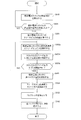
- FIG. 2 is a flowchart showing an example of a processing procedure related to a method for stopping the fuel cell system 10 in the present embodiment.
- the processing procedure of this stopping method is repeatedly performed at a predetermined cycle, for example, several ms (milliseconds).
- step S910 the control unit 6 supplies anode gas and cathode gas to the fuel cell stack 1 to cause the fuel cell stack 1 to generate power according to the load. That is, the control unit 6 performs power generation control of the fuel cell stack 1.
- control unit 6 drives the compressor 32 and opens the cathode flow rate control valve 34 according to the state of the battery 52 and the drive motor 53. As a result, air as the cathode gas is heated by the heating device 35 and supplied to the cathode electrode of the fuel cell stack 1 whose temperature has been raised.
- control unit 6 drives the pump 21 and opens the fuel supply valve 23 according to the state of the battery 52 and the drive motor 53.
- the reforming fuel supplied from the fuel tank 20 is vaporized by the evaporator 24, and the vaporized reforming fuel is heated by the heat exchanger 25.
- the heated reforming fuel is reformed into anode gas in the reformer 26, and this anode gas is supplied to the anode of the fuel cell stack 1.
- step S920 the control unit 6 determines whether or not a stop command signal for the fuel cell system 10 is received from the operation unit 101. If the control unit 6 has not received the stop command signal, the process returns to the process of step S910 to continue the power generation control.
- step S921 the control unit 6 stops the supply of the anode gas to the fuel cell stack 1 when the stop command signal of the fuel cell system 10 is received.
- the control unit 6 closes the anode air supply valve 341, stops driving the pump 21, and closes the fuel supply valve 23. As a result, the supply of fuel to the evaporator 24 is stopped, and thus the supply of anode gas to the fuel cell stack 1 is stopped.
- step S922 the control unit 6 stops supplying the anode gas to the fuel cell stack 1, and then supplies air to the exhaust combustor 40 based on the amount of unburned fuel gas that stays in the fuel cell system 10. Thereby, in the stop control of the fuel cell system 100, the anode off gas discharged from the fuel cell stack 1 can be appropriately burned by the exhaust combustor 40.
- the above-mentioned amount of unburned fuel gas may be obtained by experimentation of the amount of unburned fuel gas remaining in the anode gas flow path from the fuel supply valve 23 to the exhaust combustor 40.
- a map of the unburned fuel gas amount for each temperature of the fuel cell stack 1 at the time of the stop command and the injection amount of the fuel supply valve 23 immediately before the stop command is stored in the computer, and the fuel cell stack at the time of the stop command is stored.
- the amount of unburned fuel gas corresponding to the temperature state of 1 may be called.
- the flow rate of the oxidant gas supplied to the exhaust combustor 40 may be set in accordance with the amount of unburned fuel gas called in the map.
- the oxidant gas flow rate supplied to the exhaust combustor 40 can be directly mapped.
- how much unburned fuel gas remains after the stop command is calculated, the volume of the anode gas flow path formed in the fuel cell stack 1, the state of the fuel supply system 2 (evaporator 24, etc.), and the stop command You may obtain
- the control unit 6 In order to burn the anode off gas in the exhaust combustor 40, the control unit 6 continues to drive the compressor 32 based on the amount of unburned fuel gas of the fuel cell system 10, for example, and sets the opening of the cathode flow control valve 34. Control. As a result, air at a flow rate necessary to burn the unburned fuel gas is supplied to the exhaust combustor 40 via the fuel cell stack 1, so that the anode off gas can be reliably burned by the exhaust combustor 40. It becomes possible.
- the control unit 6 opens the combustor air control valve 312 based on the unburned fuel gas amount of the fuel cell system 10, thereby using the reforming temperature control air passage 311 without going through the fuel cell stack 1. Air may be supplied to the exhaust combustor 40.
- the pressure in the anode gas supply passage 22 downstream from the evaporator 24 is set to the outlet pressure of the exhaust combustor 40. Maintained at a high level. For this reason, the unburned fuel gas staying in the anode gas supply passage 22 is discharged as an anode off-gas to the exhaust combustor 40 through the anode electrode of the fuel cell stack 1.
- unburned fuel gas such as the unburned gas that stays in the reformer 26 or the anode gas that stays in the fuel cell stack 1 when the anode gas supply is stopped is burned in the exhaust burner 40 and discharged to the outside air. Will be able to. Therefore, after the fuel cell system 10 is stopped, when the EV key is set to ON again and the start-up control is executed, the discharge of unburned fuel gas from the fuel cell system 10 to the outside air can be suppressed.
- the control unit 6 stops the supply of the anode gas to the fuel cell stack 1 and reduces the amount of unburned fuel gas remaining in the fuel cell system 10. Based on this, the exhaust combustor 40 is operated.
- control unit 6 receives the stop command signal for the fuel cell system 10 in step S920, the control unit 6 stops driving the compressor 32 and stops the supply of air to the fuel cell stack 1. May be.
- a fuel cell system 10 includes an oxidant supply system 3 that supplies oxidant gas to the fuel cell stack 1, and a fuel supply system 2 that supplies fuel gas to the fuel cell stack 1. And an exhaust combustor 40 that introduces an anode off-gas and a cathode off-gas discharged from the fuel cell stack 1 and burns and discharges the mixed gas.
- the control unit 6 of the fuel cell system 10 performs a power generation control step of supplying the fuel gas and oxidant gas to the fuel cell stack 1 to generate power in the fuel cell stack 1.
- the control unit 6 stops the supply of the anode gas to the fuel cell stack 1, and the exhaust combustor is based on the amount of unburned fuel gas remaining in the fuel cell system 10.
- a stop control step of supplying air as cathode gas to 40 is executed.
- air is supplied through the fuel cell stack 1 by supplying air from the oxidant supply system 3 to the exhaust combustor 40 at a flow rate corresponding to the amount of unburned fuel gas remaining in the fuel cell system 10.
- the anode off gas can be combusted in the exhaust combustor 40. Therefore, the amount of unburned fuel gas remaining in the fuel cell system 10 after the stop control ends is reduced, so that the amount of unburned fuel gas discharged at the next startup of the fuel cell system 10 can be suppressed.
- the amount of air supplied to the exhaust combustor 40 is set in consideration of the amount of unburned fuel gas that remains in the fuel supply system 2 when the anode gas supply is stopped, more air than necessary is supplied to the exhaust combustor 40. It is possible to avoid a situation in which the temperature of the exhaust combustor 40 is excessively lowered by supplying. Therefore, the unburned fuel gas can be reliably burned and exhausted while maintaining the internal temperature of the exhaust combustor 40 at a temperature at which the unburned fuel gas can be combusted appropriately.
- the control unit 6 supplies air as an oxidant gas to the exhaust combustor 40 using the reforming temperature control air passage 311 that is a bypass flow path of the fuel cell stack 1. May be.
- the fuel cell stack 1 is to be restarted immediately after the stop command and performing a process for maintaining the temperature of the fuel cell stack 1 for a specific period, without cooling the fuel cell stack 1,
- the exhaust combustor 40 can be warmed. Therefore, the time required for the restart control immediately after the stop command can be shortened.
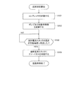
- FIG. 3 is a flowchart showing an example of a processing procedure relating to a method for stopping the fuel cell system according to the second embodiment of the present invention.
- the basic configuration of the fuel cell system of this embodiment is the same as the configuration of the fuel cell system 10 shown in FIG. In the following, the same components as those of the fuel cell system 10 shown in FIG.
- the stopping method of the fuel cell system 10 of this embodiment includes steps S923 and S924 in addition to steps S910, S920, and S921 shown in FIG. Further, steps S922a and S922b are provided instead of step S922. Here, only the processes of steps S922a, S922b, S923, and S924 will be described in detail.
- step S922a the control unit 6 stops the supply of the anode gas to the fuel cell stack 1, and then discharges the anode off gas from the fuel cell stack 1 to the exhaust combustor 40.
- step S922b the control unit 6 supplies the exhaust combustor 40 with a predetermined amount of air necessary for burning the unburned fuel gas remaining in the fuel cell system 10 when the supply of the anode gas is stopped.
- This predetermined amount is set by the amount of unburned fuel gas that stays in the fuel cell system 10.
- the predetermined amount is set in advance in consideration of the internal volumes of the anode gas supply passage 22, the reformer 26, the fuel cell stack 1, and the like necessary for obtaining the unburned fuel gas amount.
- the oxygen molar amount of the ratio of carbon (C) to the molar amount of (O 2) (C / O 2) is greater than 1, and the combustion temperature of the exhaust combustor 40 is unburned fuel gas
- the predetermined amount is set so that the temperature does not fall below the lower limit temperature required.
- a map showing the relationship between the amount of fuel injected into the evaporator 24 and the amount of unburned fuel gas remaining in the anode gas supply passage 22 when receiving a stop command signal is prepared in advance using experimental data, simulation results, or the like.
- the amount of unburned fuel gas stayed is obtained by referring to the map, and the flow rate of air to be supplied to the exhaust combustor 40 is set based on the stay amount. Good.
- the anode off-gas discharged to the exhaust combustor 40 can be reliably burned.
- the temperature of the exhaust combustor 40 is excessively lowered and the exhaust combustor 40 cannot combust unburned fuel gas. Can be avoided and the power consumption of the compressor 32 can be reduced.
- the control unit 6 in the present embodiment continues to drive the compressor 32 and opens the cathode flow rate control valve 34 to supply a predetermined amount of air to the exhaust combustor 40 through the fuel cell stack 1. Thereby, oxygen shortage in the exhaust combustor 40 can be avoided while the fuel cell stack 1 is cooled by the air discharged from the compressor 32.
- the control unit 6 may supply air to the exhaust combustor 40 without passing through the fuel cell stack 1 by closing the cathode flow rate control valve 34 and opening the combustor air control valve 312. Thereby, since the temperature drop of the fuel cell stack 1 is suppressed, the fuel cell system 10 can be started early even if a restart command is issued during the stop control of the fuel cell system 10. it can.
- step S923 after receiving the stop command signal of the fuel cell system 10, the control unit 6 determines whether or not the forced discharge time in the stop control has come.
- the control unit 6 includes a timer that measures an elapsed time from the stop command, starts counting the timer when a stop command signal is received, and forcibly discharges when the count value has passed a predetermined time. Judge that it is time.
- the predetermined time here is a predetermined value for suppressing the oxidation of the anode electrode in the fuel cell.
- the temperature characteristic of the fuel cell stack 1 after the stop command and the pressure in the anode gas supply passage 22 are set. It can be determined using characteristics or the like.
- step S924 the control unit 6 supplies the cathode gas air to the anode gas supply passage 22 when determining that the forced discharge time has come.
- control unit 6 opens the anode air supply valve 341 when the forced discharge time comes.
- the air discharged from the compressor 32 is supplied to the heat exchanger 25 and the reformer 26 and the pressure in the anode gas supply passage 22 is increased, so that it remains in the reformer 26, the fuel cell stack 1 and the like.
- the unburned fuel gas etc. which have been can be pushed out to the exhaust combustor 40.
- control unit 6 determines the flow rate of air necessary to push the unburned fuel gas staying inside the reformer 26 to the exhaust combustor 40 when the forced discharge time comes. 22 is supplied. After supplying air to the anode gas supply passage 22 by a predetermined flow rate, the controller 6 closes the anode air supply valve 341 and stops driving the compressor 32. Thereby, stop control of the fuel cell system 10 is completed.
- step S924 When the processing in step S924 is completed, a series of processing procedures (S910 to S924) regarding the control method of the fuel cell system 10 in the present embodiment is completed. In addition, about each process of step S922a and step S922b, you may perform simultaneously, or you may make it perform the process of step S922b prior to the process of step S922a.
- FIG. 4 is a flowchart showing another example of the processing procedure relating to the method of stopping the fuel cell system.
- step S923a shown in FIG. 3
- step S922c, S931, and S932 Since the other processes are the same as those shown in FIG. 3, only the processes of steps S922c, S923a, S931, and S932 will be described in detail.
- step S922c the control unit 6 performs exhaust from the compressor 32 based on the temperature of the exhaust gas discharged from the exhaust combustor 40 so that the temperature of the exhaust combustor 40 does not fall below the temperature necessary for combustion of the unburned fuel gas.
- the flow rate of air supplied to the combustor 40 is controlled.
- the control unit 6 decreases the air flow rate set in step S922b.
- the combustion lower limit temperature referred to here is a lower limit value of the temperature necessary for burning the unburned fuel gas in the exhaust combustor 40.
- the control unit 6 reduces the flow rate of air to be supplied to the exhaust combustor 40 as the combustor outlet temperature falls within a range where the combustor outlet temperature does not fall below the combustion lower limit temperature. You may make it increase the air flow volume which should be supplied to the exhaust combustor 40, so that it rises.
- control unit 6 corrects the flow rate of air to be supplied to the exhaust combustor 40 in accordance with the temperature of the exhaust combustor 40. Thereby, the temperature of the exhaust combustor 40 can be maintained at a temperature required for combustion of the unburned fuel gas.
- step S931 the control unit 6 acquires the temperature of the fuel cell stack 1.
- the control unit 6 detects the stack inlet temperature detected by the temperature sensor 62, the stack outlet temperature detected by the temperature sensor 63, the cathode inlet temperature detected by the temperature sensor 66, and the temperature sensor 67.
- the temperature of the fuel cell stack 1 is estimated using the cathode outlet temperature.
- control unit 6 estimates the temperature of the fuel cell stack 1 based on the stack inlet temperature detected by the temperature sensor 62 and the stack outlet temperature detected by the temperature sensor 63.
- the control unit 6 calculates the average value obtained by dividing the sum of the stack inlet temperature and the stack outlet temperature by 2 as the temperature of the fuel cell stack 1. Accordingly, it is possible to more accurately determine whether or not the temperature of the fuel cell stack 1 has decreased to a temperature at which the oxidation reaction is unlikely to occur at the anode electrode, as compared with the case where the average value of the cathode inlet temperature and the cathode outlet temperature is used. It becomes possible. Note that a temperature sensor for detecting the temperature of the anode electrode of the fuel cell stack 1 may be provided in the fuel cell stack 1, and the detection value of the temperature sensor may be used.
- step S923a the control unit 6 determines whether or not the temperature of the fuel cell stack 1 has decreased with respect to a temperature threshold value Tth that is set to suppress oxidation of the anode electrode in the fuel cell stack 1.
- the temperature threshold Tth is set to 300 ° C., for example.
- step S922 is repeatedly executed until the temperature of the fuel cell stack 1 becomes lower than the temperature threshold value Tth.
- step S924 when the temperature of the fuel cell stack 1 becomes lower than the temperature threshold value Tth, the control unit 6 determines that the forced discharge time has come, and opens the anode air supply valve 341. As a result, air is supplied from the compressor 32 to the anode gas supply passage 22 via the oxidation reforming passage 331.
- step S932 when the combustion of the unburned fuel gas in the exhaust combustor 40 is completed, the control unit 6 stops driving the compressor 32, and the series of processing procedures for the method of stopping the fuel cell system 10 is completed.
- FIG. 5 is a diagram for explaining the forced discharge timing in the stop control of the fuel cell system 10.
- FIG. 5A is a diagram showing a change in the internal temperature of the fuel cell stack 1.
- FIG. 5B is a diagram showing a change in the opening degree of the anode air supply valve 341. These horizontal axes are time axes common to each other.
- 5 (a) and 5 (b) show a case where air is continuously supplied to the cathode electrode of the fuel cell stack 1 by opening the cathode flow rate control valve 34 when the fuel cell system 10 is stopped.
- the forced discharge time is indicated by a dotted line.
- a solid line indicates the forced discharge timing when the supply of air to the cathode electrode is stopped by closing the cathode flow rate control valve 34 and opening the combustor air control valve 312.
- a stop command signal is transmitted to the control unit 6 by the operation unit 101, and when the control unit 6 receives the stop command signal, the control unit 6 starts stop control for stopping the fuel cell system 10.
- the temperature of the fuel cell stack 1 gradually decreases. Therefore, as shown by the solid line in FIG. 5B, the temperature of the fuel cell stack 1 becomes lower than the temperature threshold value Tth at time t2, so that the anode air supply valve 341 is opened. Thereby, the unburned fuel gas staying inside the reformer 26 and the fuel cell stack 1 can be burned by the exhaust combustor 40 while suppressing the oxidation of the anode electrode in the fuel cell stack 1.
- a heater is disposed around the exhaust combustor 40 to warm the exhaust combustor 40 so that the temperature of the exhaust combustor 40 does not decrease too much. You may do it.
- a passage that branches from the cathode gas discharge passage 39 and bypasses the exhaust combustor 40 is provided, and a part of the air discharged from the cathode side of the fuel cell stack 1 is discharged without passing through the exhaust combustor 40. You may do it.
- the temperature of the fuel cell stack 1 becomes lower than the temperature threshold Tth, and the anode air supply valve 341 is opened as shown by the dotted line in FIG.
- the unburned fuel gas remaining in the anode gas supply passage 22 is pushed out by the air supplied from the anode air supply valve 341, so that the pushed unburned fuel gas is burned in the exhaust combustor 40. For this reason, it is possible to suppress the discharge of unburned fuel gas during the next start-up control while shortening the stop control time until the stop control of the fuel cell system 10 is completed.
- the cathode gas is forcibly supplied from the compressor 32 to the anode gas supply passage 22, so that the unburned gas stayed in the reformer 26 and the fuel cell stack 1.
- the fuel gas can be burned in the exhaust combustor 40. Therefore, the amount of unburned fuel gas discharged from the exhaust passage 41 to the atmosphere at the next startup of the fuel cell system 10 can be reduced.
- air is supplied to the anode gas supply passage 22 through the oxidation reforming passage 331.
- the air supply passage is branched from the cathode gas supply passage 33 between the heating device 35 and the fuel cell stack 1 and merges with the anode gas supply passage 22 between the heat exchanger 25 and the reformer 26. May be provided in the fuel cell system 10 so that air is supplied to the anode gas supply passage 22 by opening an on-off valve provided in the air supply passage when the forced discharge timing comes.
- the compressor 32 is used to supply air to the anode gas supply passage 22 at the forced discharge timing.
- the present invention is not limited to this.
- a new air supply device different from the compressor 32 may be provided in the fuel cell system 10 so that air is supplied to the anode gas supply passage 22 using this air supply device when the forced discharge time comes. .
- FIG. 6 is a flowchart showing another example of a processing procedure related to a method for stopping the fuel cell system 10.
- steps S922d and S923b instead of steps S922b and S923 shown in FIG. 3, and newly includes steps S941 and S942. Since the other processes are the same as those shown in FIG. 3, only the processes of steps S922d, S923b, S941 and S942 will be described in detail.
- step S922d the control unit 6 controls the flow rate of air supplied from the compressor 32 to the exhaust combustor 40 in accordance with the pressure in the anode gas supply passage 22.
- the control unit 6 acquires the stack inlet anode pressure from the pressure sensor 61, and based on the stack inlet anode pressure, the control unit 6 uses the predetermined map or arithmetic expression to determine whether the exhaust gas is discharged to the exhaust combustor 40. Calculate the flow rate of the fuel gas.
- the control unit 6 supplies an air flow rate according to the calculated flow rate of the unburned fuel gas to the exhaust combustor 40.
- the control unit 6 decreases the flow rate of air discharged from the fuel cell stack 1 to the exhaust combustor 40 in accordance with a change in the stack inlet anode pressure.
- the controller 6 decreases the opening of the cathode flow rate control valve 34 as the stack inlet anode pressure decreases. Thereby, the flow rate of the air discharged to the exhaust combustor 40 through the fuel cell stack 1 can be reduced.
- the control unit 6 uses the map showing the relationship between the stack inlet anode pressure and the air flow rate required for the combustion of the exhaust combustor 40 to control the air flow rate to the exhaust combustor 40 based on the stack inlet anode pressure. It is possible to control.
- control unit 6 acquires the combustor outlet pressure from the pressure sensor 65, and the air discharged from the fuel cell stack 1 to the exhaust combustor 40 based on the pressure difference between the stack inlet anode pressure and the combustor outlet pressure.
- the flow rate may be controlled.
- step S923b the control unit 6 acquires the stack inlet anode pressure from the pressure sensor 61, and determines whether or not the stack inlet anode pressure has decreased to a predetermined pressure threshold value Pth.
- the pressure threshold value Pth here is set based on the minimum pressure value required to discharge the gas staying inside the reformer 26 to the exhaust combustor 40.
- the pressure threshold value Pth is set to a value obtained by adding a combustor outlet pressure detected by the pressure sensor 65 or a fixed value in consideration of an error or the like to the combustor outlet pressure.
- step S922a When the stack inlet anode pressure is higher than the pressure threshold Pth, the unburned fuel gas staying in the reformer 26 is discharged to the exhaust combustor 40, so the control unit 6 is not in the forced discharge timing. It returns to the process of step S922a. Then, the process of step S922a is repeatedly executed until the stack inlet anode pressure decreases toward the pressure threshold value Pth.
- step S941 the control unit 6 controls the DC-DC converter 51 to apply a reverse bias voltage to the fuel cell stack 1 when the stack inlet anode pressure is equal to or lower than the pressure threshold Pth. That is, the control unit 6 applies a higher potential to the negative electrode terminal of the fuel cell stack 1 than the potential applied to the positive electrode terminal of the fuel cell stack 1. Thereby, even if oxygen is supplied to the anode gas flow path of the fuel cell stack 1, the oxidation of the anode electrode can be suppressed.
- step S924 air is forcibly supplied to the anode gas supply passage 22 to push the unburned fuel gas remaining inside the reformer 26, the fuel cell stack 1 and the like to the exhaust combustor 40. be able to.
- step S932 the driving of the compressor 32 is stopped in step S932.
- the control unit 6 supplies air from the compressor 32 to the fuel cell stack 1 so that the temperature of the fuel cell stack 1 is higher than the temperature threshold value Tth.
- the driving of the compressor 32 may be stopped when the pressure drops.
- step S942 the control unit 6 stops applying the reverse bias voltage to the fuel cell stack 1 and stops driving the DC-DC converter 51.
- the air supply to the anode gas supply passage 22 is stopped until the stack inlet anode pressure reaches the pressure threshold value Pth after receiving the stop command signal, thereby suppressing the oxidation of the anode electrode and the compressor 32.
- Driving can be suppressed. Therefore, the power consumption of the compressor 32 can be reduced while suppressing a decrease in the power generation performance of the fuel cell stack 1.
- the time for applying the reverse bias voltage to the fuel cell stack 1 can be shortened, the power required for driving the DC-DC converter 51 can be reduced.
- the reverse bias voltage is applied to the fuel cell stack 1 when the stack inlet anode pressure is lower than the pressure threshold Pth.
- the present invention is not limited to this.
- the reverse bias voltage may be applied to the fuel cell stack 1 immediately after receiving the stop command signal in step S920. Thereby, the oxidation of the anode electrode of the fuel cell stack 1 when the fuel cell system 10 is stopped can be more reliably suppressed.
- control unit 6 may execute the processes of step S922a and step S922d at the same time, or may execute the process of step S922d prior to the process of step S922a. Further, the control unit 6 may execute step S922b shown in FIG. 3 instead of the process of step S922d, or may execute the processes of steps S922b and S922c shown in FIG. .
- FIG. 7 is a diagram showing the forced discharge timing in the stop control of the fuel cell system 10 shown in FIG.
- FIG. 7A is a graph showing changes in the pressure of the anode gas supplied to the fuel cell stack 1 (stack inlet anode pressure).
- FIG. 7B is a diagram showing a change in the opening degree of the anode air supply valve 341. These horizontal axes are time axes common to each other.
- FIG. 7A the stack inlet anode pressure when the anode air supply valve 341 is opened after the stop command of the fuel cell system 10 is shown by a solid line, and the anode air supply valve 341 is kept closed without being opened.
- the stack inlet anode pressure in this state is indicated by a dotted line.
- the operation unit 101 supplies a stop command signal to the control unit 6.
- the control unit 6 executes stop control of the fuel cell system 10.
- the control unit 6 continues to drive the compressor 32 and opens the cathode flow rate control valve 34, whereby the flow rate corresponding to the amount of unburned fuel gas is supplied to the exhaust combustor 40 via the fuel cell stack 1. Supply the air.
- the control unit 6 stops driving the pump 21 and closes the fuel supply valve 23. As a result, the supply of the anode gas to the fuel cell stack 1 is stopped, so the pressure in the anode gas supply passage 22 (stack inlet anode pressure) decreases.
- the stack inlet anode pressure decreases to the pressure threshold value Pth.
- the differential pressure between the stack inlet anode pressure and the combustor outlet pressure becomes smaller, so the amount of anode off-gas discharged from the fuel cell stack 1 to the exhaust combustor 40 decreases. Therefore, a reverse bias voltage is applied to the fuel cell stack 1 by the DC-DC converter 51, and the anode air supply valve 341 is fully opened or set to a predetermined opening as shown in FIG. 7B.
- the control unit 6 controls the compressor 32 and the cathode flow rate control valve 34, and gradually decreases the flow rate of air supplied to the exhaust combustor 40, similarly to the time characteristic shown in FIG. Thereby, since surplus air supply to the exhaust combustor 40 can be suppressed, the power consumption of the compressor 32 can be suppressed and the temperature drop of the exhaust combustor 40 can be suppressed.
- the forced discharge timing is determined based on the stack inlet anode pressure.
- the forced discharge timing is determined based on the differential pressure between the stack inlet anode pressure and the combustor outlet pressure. You may make it judge whether it became.
- the control unit 6 supplies air, which is an oxidant gas, to the anode gas supply passage (fuel passage) 22 when the fuel cell system 10 is stopped. Accordingly, the unburned fuel gas that has stayed in the anode gas supply passage 22 and the fuel cell stack 1 can be reliably pushed out from the fuel cell stack 1 as the anode off-gas, so that the unburned fuel stays in the anode gas supply passage 22.
- the gas can be combusted in the exhaust combustor 40.
- the fuel supply system 2 includes the reformer 26 that reforms the fuel gas heated by the exhaust combustor 40, and the oxidant supply system 3 includes the cathode gas supply passage (oxidation).
- the oxidation reforming passage 331 is included as a branch passage that branches from the agent passage 33 and joins the anode gas supply passage 22 located upstream of the reformer 26.
- the control unit 6 supplies air from the oxidation reforming passage 331 to the anode gas supply passage 22 using the compressor 32.
- unburned fuel gas staying inside the reformer 26 can be burned by the exhaust combustor 40. Since a large amount of unburned fuel gas stays inside the reformer 26 provided in the anode gas supply passage 22, a larger amount of unburned fuel gas is supplied by supplying air from the upstream side of the reformer 26. It can be burned by the exhaust combustor 40. For this reason, the amount of unburned fuel gas discharged at the next start-up can be further reduced.
- the oxidation reforming passage 331 is a branch passage that supplies air instead of the steam used for the reforming reaction, and the oxidant supply system 3 is provided in the oxidation reforming passage 331.
- an anode air supply valve (control valve) 341 for controlling the flow rate of the air supplied to the reformer 26 is further included.
- the control unit 6 receives a stop command signal for the fuel cell system 10
- the control unit 6 stops the power generation of the fuel cell stack 1 by stopping the supply of the anode gas, that is, after a predetermined waiting period has elapsed, that is, the forced discharge timing.
- the anode air supply valve 341 is opened.
- the temperature of the fuel cell stack 1 is lowered to some extent by waiting to supply air to the anode electrode for a predetermined waiting period, which is accompanied by the supply of air to the anode gas supply passage 22.
- the progress of the oxidation reaction of the anode electrode can be suppressed.
- the unburned fuel gas is discharged during this period using the differential pressure between the stack inlet anode pressure and the combustor outlet pressure. There is no need to supply air. Therefore, the total amount of air supplied to the anode gas supply passage 22 can be reduced, and oxidation of the anode electrode can be suppressed.
- the above-described standby period is determined based on, for example, the temperature of the fuel cell stack 1.
- air can be supplied to the anode gas supply passage 22 when the temperature of the fuel cell stack 1 decreases to a temperature at which the occurrence of the oxidation reaction of the anode electrode can be suppressed.
- the unburned fuel gas staying in the anode gas supply passage 22 can be reliably burned while suppressing the oxidation of the anode electrode.
- the standby period may be obtained by experiment or the like in consideration of the time characteristic of the stack temperature with respect to the supply amount of the cathode gas to the fuel cell stack 1 in the stop control, for example, the characteristic shown in FIG.
- a map of the standby time for each supply amount of the cathode gas may be stored in a computer, and the standby time may be called according to the supply state of the cathode gas at the time of the stop command.
- the standby period described above may be determined based on the anode gas pressure of the fuel cell stack 1.
- the standby period may be obtained by experiments or the like in consideration of the time characteristics related to the pressure in the anode gas supply passage 22 after the anode gas supply is stopped, for example, the characteristics shown in FIG.
- a map of the standby time for each stack inlet anode pressure at the time of the stop command may be stored in a computer, and the standby time may be called according to the pressure state of the anode gas supply passage 22 at the time of the stop command.
- the control unit 6 when the fuel cell system 10 is stopped, the control unit 6 causes the fuel cell stack 1 from the external DC-DC converter 51 after the standby period has elapsed since the stop of the fuel cell stack 1.
- a reverse bias voltage (back electromotive force) is applied to the anode gas supply passage 22 and air is supplied to the anode gas supply passage 22.
- the unburned fuel gas remaining in the anode gas supply passage 22 can be discharged to the exhaust combustor 40 while suppressing the oxidation of the anode electrode due to the supply of air to the anode gas supply passage 22. . For this reason, it is possible to suppress discharge of unburned fuel gas from the fuel cell system 10 to the outside air while suppressing a decrease in power generation performance of the fuel cell stack 1.
- the example in which the reverse bias voltage is applied from the DC-DC converter 51 to the fuel cell stack 1 has been described.
- an electric circuit different from the DC-DC converter 51 is provided in the fuel cell stack 1 and the electric circuit is used.
- a reverse bias voltage may be applied to the fuel cell stack 1.
- control unit 6 determines that the anode when the stack inlet anode pressure, the temperature of the fuel cell stack 1, and the elapsed time after the stop command exceed a predetermined threshold value.
- the system air supply valve 341 is opened.
- the control unit 6 determines the fuel cell based on the stack inlet temperature that is the temperature of the anode gas supplied to the fuel cell stack 1 and the stack outlet temperature that is the temperature of the anode offgas discharged from the fuel cell stack 1.
- the temperature of the anode electrode in the stack 1 is calculated.
- the control unit 6 determines that the anode system when the temperature of the fuel cell stack 1 is lower than the temperature threshold Tth determined to suppress the oxidation of the fuel cell stack 1.
- the air supply valve 341 is opened to supply air to the anode gas supply passage 22. As described above, since air is supplied to the anode gas supply passage 22 in a state where the oxidation reaction of the anode electrode of the fuel cell stack 1 is less likely to occur, deterioration of the fuel cell stack 1 can be suppressed.
- the control unit 6 opens the anode air supply valve 341 when the stack inlet anode pressure becomes lower than a predetermined pressure threshold value Pth. Accordingly, unburned fuel gas is discharged to the exhaust combustor 40 due to the pressure difference between the stack inlet anode pressure and the combustor outlet pressure without supplying air to the anode gas supply passage 22. The amount of air supply to can be reduced. Therefore, oxidation of the anode electrode in the fuel cell stack 1 can be suppressed.
- control unit 6 includes a timer for measuring time, which is required for the time required for the temperature of the fuel cell stack 1 to reach the temperature threshold Tth after the stop command, or for the stack inlet anode pressure to reach the pressure threshold Pth.
- the time is stored in advance, the timer starts counting when a stop command signal is received, and the anode air supply valve 341 is kept closed until the count value passes the prestored time. .
- control unit 6 determines that the anode system when at least one parameter of the pressure of the anode gas supply passage 22, the temperature of the fuel cell stack 1, and the elapsed time after the stop command exceeds a predetermined threshold value. Open the air supply valve 341. Thereby, supply of air to the anode gas supply passage 22 more than necessary can be suppressed and deterioration of the fuel cell stack 1 can be suppressed.
- control unit 6 closes the anode air supply valve 341 and continues to drive the compressor 32 until a predetermined period elapses after receiving the stop command, and the cathode gas supply passage. Air is supplied to 33.
- the fuel cell stack 1 can be cooled.
- unburned fuel gas can be appropriately burned by the exhaust combustor 40. That is, the stop control of the fuel cell system 10 can be completed early, and the unburned fuel gas staying in the fuel cell system 10 can be reliably burned.
- the oxidant supply system 3 includes a reforming temperature control air passage 311 as a bypass passage that branches from the oxidant passage and merges with the cathode gas discharge passage 39 of the fuel cell stack 1 via the exhaust combustor 40. Then, the control unit 6 opens the combustor air control valve 312 for a predetermined period after the stop command and supplies air to the exhaust combustor 40 through the reforming temperature control air passage 311. Thereby, the situation where the oxygen used for combustion of the unburned fuel gas in the exhaust combustor 40 is insufficient can be avoided.
- control unit 6 supplies air to the exhaust combustor 40 by a predetermined flow rate when the fuel cell system 10 is stopped. Therefore, since it can suppress supplying air excessively to the exhaust combustor 40 using the compressor 32, the power consumption of the compressor 32 can be reduced.
- the fuel cell system 10 includes the temperature sensor 64 that detects the temperature of the exhaust gas discharged from the exhaust combustor 40 (combustor outlet temperature), and the control unit 6 includes the temperature sensor 64.
- the flow rate of the air to be supplied to the exhaust combustor 40 is reduced based on the combustor outlet temperature detected by.
- control unit 6 reduces the flow rate of the air supplied to the exhaust combustor 40 when the combustor outlet temperature decreases with respect to a predetermined combustion lower limit temperature.
- the control unit 6 reduces the flow rate of the air supplied to the exhaust combustor 40 when the combustor outlet temperature decreases with respect to a predetermined combustion lower limit temperature.
- the control unit 6 performs exhaust combustion from the compressor 32 when stopping the fuel cell system 10.
- the flow rate of air supplied to the vessel 40 is gradually reduced. Thereby, the power consumption of the compressor 32 can be reduced while avoiding oxygen shortage in the exhaust combustor 40 during stop control.
- the fuel cell system 10 includes the pressure sensor 61 that detects the pressure of the anode gas supplied to the fuel cell stack 1 (stack inlet anode pressure), and the exhaust discharged from the exhaust combustor 40. And a pressure sensor 65 that detects a gas pressure (combustor outlet pressure). Then, the control unit 6 reduces the flow rate of the air supplied to the exhaust combustor 40 based on the difference between the combustor outlet pressure and the stack inlet anode pressure or only the stack inlet anode pressure. As a result, the air flow rate is more accurately adjusted in accordance with the flow rate of the unburned fuel gas supplied to the exhaust combustor 40, so that the power consumption of the compressor 32 can be further reduced.
- the pressure sensor 61 that detects the pressure of the anode gas supplied to the fuel cell stack 1 (stack inlet anode pressure), and the exhaust discharged from the exhaust combustor 40.
- a pressure sensor 65 that detects a gas pressure (combustor outlet pressure).
- the fuel cell system 10 includes the DC-DC converter 51 as a power controller that is connected to the fuel cell stack 1 and extracts the power of the fuel cell stack 1 and supplies it to the battery 52.
- the control unit 6 applies a back electromotive force from the DC-DC converter 51 to the fuel cell stack 1 when stopping the fuel cell system 10. That is, in the stop control, the control unit 6 performs switching control of the DC-DC converter 51 and applies a higher potential to the negative electrode terminal of the fuel cell stack 1 than the potential applied to the positive electrode terminal of the fuel cell stack 1.
- FIG. 8 is a diagram showing an example of the configuration of the fuel cell system 11 according to the third embodiment of the present invention.
- the fuel cell system 11 includes a heat exchanger 351, a diffusion combustor 352, and a catalytic combustor 353 instead of the heating device 35 of the fuel cell system 10 shown in FIG. Further, the fuel cell system 11 includes a branch passage 332 for passing air from the compressor 32 to the catalyst combustor 353, and a branch passage for passing fuel gas from the pump 21 to each of the exhaust combustor 40, the diffusion combustor 352, and the catalyst combustor 353. 211, 212, and 213. Control valves 342, 231, 232, and 232 are provided in the branch passages 332, 211, 212, and 213, respectively.
- shutoff valve 28 is attached to the anode gas discharge passage 29.
- the shutoff valve 28 is closed after the stop control of the fuel cell system 11 is completed.
- the backflow of cathode off gas or the like in the anode gas discharge passage 29 is prevented, and deterioration of the anode is suppressed.
- a relief valve 36 is attached to the cathode gas supply passage 33.
- the cathode gas supply passage 33 is opened to prevent the compressor 32 from being subjected to a certain load.
- the control valve 342 supplies a certain amount of air to the catalytic combustor 353 when the fuel cell stack 1 is activated, and closes the branch passage 332 after the activation is completed.
- the heat exchanger 351 heats the air for the combustion gas or the air for the cathode gas by using the heat of the exhaust gas discharged from the exhaust combustor 40.
- the diffusion combustor 352 is supplied with the air heated by the heat exchanger 351 and the heating fuel supplied from the branch passage 212 and heated by the electric heater 242 when the fuel cell system 10 is started. Mix. Then, a mixture of air and heating fuel is ignited by an ignition device attached to the diffusion combustor 352 to form a preheating burner for the catalytic combustor 353. After the start-up, the air supplied from the heat exchanger 351 is supplied to the catalytic combustor 353.
- the catalyst combustor 353 generates high-temperature combustion gas using a catalyst and a preheating burner at the time of startup.
- combustion gas air is supplied through the branch passage 332, and heating fuel is supplied from the branch passage 213, and the two are mixed in contact with the catalyst.
- a large amount of combustion gas is produced
- This combustion gas does not contain oxygen and is mainly composed of an inert gas.
- the combustion gas is supplied to the cathode electrode of the fuel cell stack 1 to heat the fuel cell stack 1. After the start-up is completed, the generation of the combustion gas is completed, and the air that has passed through the heat exchanger 351 and the diffusion combustor 352 is supplied to the fuel cell stack 1 as a cathode gas.
- Control valves 231, 232, and 233 open the branch passages 211, 212, and 213 when the fuel cell system 10 is started to flow the heating fuel, and close the branch passages 211, 212, and 213 when the start-up is completed.
- the fuel supply valve 23 closes the anode gas supply passage 22 at the time of start-up, but opens the anode gas supply passage 22 to allow the reforming fuel to flow at the end of the start-up.
- the exhaust combustor 40 When the fuel cell system 10 is started up, the exhaust combustor 40 is supplied with heating fuel supplied from the branch passage 211 and heated by the electric heater 241, and the combustion gas that has passed through the fuel cell stack 1 and the reforming temperature. The air introduced from the control air passage 311 is mixed and the exhaust combustor 40 is heated by a catalytic reaction.
- FIG. 9 is a flowchart showing an example of a processing procedure related to start-up control for starting up the fuel cell system 11.
- step S101 the control unit 6 activates the compressor 32 and opens the cathode flow rate control valve 34, the anode air supply valve 341, and the control valve 342 at a certain opening degree. .
- air combustion gas
- step S102 the controller 6 activates the pump 21 and the diffusion combustor 352 (ignition device) and opens the control valves 231 to 233.
- the heating fuel is supplied to each of the diffusion combustor 352, the catalytic combustor 353, and the exhaust combustor 40.
- a preheating burner is formed in the diffusion combustor 352, combustion gas is generated in the catalytic combustor 353 using the preheating burner, and the combustion gas passes through the fuel cell stack 1 to heat the fuel cell stack 1. Further, the combustion gas that has passed through the fuel cell stack 1 reaches the exhaust combustor 40, and the exhaust combustor 40 is heated and the heat exchanger 25 is heated by catalytic combustion with the heating fuel. Further, the evaporator 24 and the heat exchanger 351 are heated by the exhaust gas from the exhaust combustor 40.
- step S103 the control unit 6 determines whether or not the temperature of the fuel cell stack 1 has reached the operating temperature necessary for power generation.
- the control unit 6 determines whether or not the temperature of the fuel cell stack 1 has reached the operating temperature necessary for power generation.
- a method for determining the temperature of the fuel cell stack for example, if the temperature of the combustion gas detected by the temperature sensor 63 exceeds a certain value, it may be determined that the fuel cell stack 1 has reached the operating temperature.
- the evaporator 24, the heat exchanger 25, and the reformer 26 are originally required to determine whether they have reached an appropriate temperature for satisfactorily reforming the reforming fuel. It is not necessary when the time for reaching the appropriate temperature is shorter than the time for the temperature of the fuel cell stack 1 to reach the operating temperature.
- step S104 the control unit 6 stops the diffusion combustor 352 and controls the control valves 342, 231, 232, 233. Are closed and the fuel supply valve 23 is opened.
- the reforming fuel from the fuel tank 20 passes through the evaporator 24, the heat exchanger 25, and the reformer 26 to become anode gas (fuel gas), and this anode gas is supplied to the anode electrode of the fuel cell stack 1.
- air is continuously supplied from the cathode flow rate control valve 34 and is heated by the heat exchanger 351 and supplied to the fuel cell stack 1 as cathode gas (oxidant gas). Then, when the electrochemical reaction by the anode gas and the cathode gas starts in the fuel cell stack 1, normal power generation is performed, and the start-up control ends.
- the reforming fuel supplied from the fuel tank 20 is vaporized by the evaporator 24, and the vaporized reforming fuel is heated by the heat exchanger 25.
- the reforming fuel is reformed into anode gas, and this anode gas is supplied to the anode electrode of the fuel cell stack 1.
- the air as the cathode gas is heated by the heat exchanger 351, passes through the diffusion combustor 352 and the catalytic combustor 353, and is supplied to the cathode electrode of the fuel cell stack 1.
- FIG. 10 is a flowchart showing an example of a processing procedure related to stop control for stopping the fuel cell system 11.
- the control unit 6 stops the pump 21 and closes the fuel supply valve 23 in step S201. As a result, the supply of the anode gas to the fuel cell stack 1 is stopped, so that the power generation of the fuel cell stack 1 is stopped. Further, the control unit 6 closes the anode air supply valve 341.
- step S202 after stopping the supply of the anode gas, the control unit 6 maintains the shutoff valve 28 provided in the anode gas discharge passage 29 in an open state without closing. Thereby, after the start of the stop control, the unburned fuel gas is discharged to the exhaust combustor 40 through the fuel cell stack 1 due to the pressure difference between the pressure of the anode gas supply passage 22 and the outlet pressure of the exhaust combustor 40.
- step S203 the control unit 6 acquires the stack inlet anode pressure from the pressure sensor 61 and calculates a target air flow rate corresponding to a predetermined air flow rate map, as in the process of step S922d in FIG.
- a target air flow rate map an air flow rate necessary for burning the unburned fuel gas discharged to the exhaust combustor 40 is set for each stack inlet anode pressure.
- step S204 the control unit 6 acquires the combustor outlet temperature from the temperature sensor 64 in the same manner as the process of step S922c in FIG. 4, and the combustor outlet temperature is low within a range in which the air in the exhaust combustor 40 is not insufficient.
- the target air flow rate is made smaller. That is, the control unit 6 corrects the target air flow rate according to the temperature of the exhaust combustor 40. Thereby, the temperature of the exhaust combustor 40 can be maintained at a temperature suitable for combustion.
- step S205 the control unit 6 continues to drive the compressor 32 and controls the opening of the cathode flow control valve 34 based on the target air flow rate calculated in step S204.
- the flow rate of the air supplied to the fuel cell stack 1 is adjusted to the target air flow rate, so that the unburned fuel gas discharged through the fuel cell stack 1 can be burned by the exhaust combustor 40.
- the inside of the fuel cell stack 1 can be cooled by the air supplied from the compressor 32 to the cathode electrode of the fuel cell stack 1.
- step S206 the control unit 6 determines whether or not the internal temperature of the fuel cell system 11 has decreased to a temperature at which the oxidation reaction hardly occurs at the anode electrode of the fuel cell stack 1. In the present embodiment, the control unit 6 determines whether or not the temperature of the fuel cell stack 1 has decreased below the temperature threshold Tth, as in the process of step S923a of FIG.
- step S207 when the temperature of the fuel cell stack 1 falls below the temperature threshold Tth, the control unit 6 opens the anode air supply valve 341 and supplies a predetermined amount of air to the anode gas supply passage 22. As a result, unburned fuel gas staying inside the reformer 26 and the fuel cell stack 1 is pushed out to the exhaust combustor 40. Then, the air supplied from the cathode flow rate control valve 34 to the exhaust combustor 40 through the fuel cell stack 1 and the unburned fuel gas are combusted, and the gas generated after the combustion is discharged to the atmosphere.
- step S ⁇ b> 208 after the unburned fuel gas staying inside the fuel cell system 11 is combusted by the exhaust combustor 40, the control unit 6 closes both the anode air supply valve 341 and the cathode flow rate control valve 34, and the compressor 32. Stop driving.
- step S209 the control unit 6 closes the shut-off valve 28 to prevent the backflow of the gas containing oxygen in the anode gas discharge passage 29 and the discharge of the residual gas that has not been accelerated from the anode gas supply passage 22.
- the shutoff valve 28 is opened at the next start-up.
- the fuel cell stack 1 when the fuel cell system 11 is stopped, by supplying air to the exhaust combustor 40, the fuel cell stack 1 is discharged.
- the unburned fuel gas can be burned in the exhaust combustor 40.
- the amount of unburned fuel gas discharged from the exhaust passage 41 through the fuel cell stack 1 at the next startup of the fuel cell system 11 can be reduced.
- the fuel cell system 10 or 11 includes a bypass passage that branches from a cathode gas supply passage 33 positioned between the cathode flow rate control valve 34 and the fuel cell stack 1 and merges with a cathode gas discharge passage 39, and the bypass passage And a control valve for controlling the flow rate of the cathode gas flowing through. Then, the control unit 6 may open the control valve of the bypass passage until the forced discharge timing comes after receiving the stop command signal.
- the fuel cell stack 1 is not cooled by air.
- the predetermined amount of air necessary for burning the unburned fuel gas can be supplied to the exhaust combustor 40.
- the present invention is suitable for a fuel cell system including a solid oxide fuel cell.
- the present invention is not limited to this.
- fuel off-gas and oxidant discharged from a polymer electrolyte fuel cell The present invention can be applied even to a fuel cell system in which off-gas is burned by a combustor and a turbine is driven by the combustion gas.
- control is performed so as to reduce the air flow rate to the exhaust combustor 40 so that the temperature of the exhaust combustor 40 does not fall too much in the stop control of the fuel cell system, but a heater is provided in the exhaust combustor 40.
- the exhaust combustor 40 may be heated by a heater.
- the inlet pressure of the fuel cell stack 1 is detected and the detected value is used as the pressure of the anode gas supply passage 22.
- the inlet pressure of the reformer 26 or the inlet of the heat exchanger 25 is used. The pressure may be detected and used. Even if it does in this way, the effect similar to 2nd Embodiment is acquired.
Landscapes
- Engineering & Computer Science (AREA)
- Chemical & Material Sciences (AREA)
- Life Sciences & Earth Sciences (AREA)
- Manufacturing & Machinery (AREA)
- Sustainable Development (AREA)
- Sustainable Energy (AREA)
- Chemical Kinetics & Catalysis (AREA)
- Electrochemistry (AREA)
- General Chemical & Material Sciences (AREA)
- Combustion & Propulsion (AREA)
- Fuel Cell (AREA)
- Electric Propulsion And Braking For Vehicles (AREA)
Abstract
Description
図1は、本発明の第1実施形態における燃料電池システム10の主要構成を示すブロック図である。
図3は、本発明の第2実施形態における燃料電池システムの停止方法に関する処理手順例を示すフローチャートである。本実施形態の燃料電池システムの基本構成は、図1に示した燃料電池システム10の構成と同じである。以下では、図1に示した燃料電池システム10と同一の構成については同一符号を付して詳細な説明を省略する。
図8は、本発明の第3実施形態における燃料電池システム11の構成の一例を示す図である。
Claims (16)
- 燃料電池に酸化剤ガスを供給する酸化剤供給装置と、前記燃料電池に燃料ガスを供給する燃料供給装置と、前記燃料電池から排出される燃料オフガスと酸化剤オフガスとを燃焼して排出する燃焼器と、を備える燃料電池システムの制御方法であって、
前記燃料電池に燃料ガス及び酸化剤ガスを供給して前記燃料電池を発電させる発電制御ステップと、
前記燃料電池システムを停止させる場合には、前記燃料電池への燃料ガスの供給を停止し、前記燃料電池システムの未燃燃料ガス量に基づいて前記燃焼器に酸化剤ガスを供給する停止制御ステップと、
を含む燃料電池システムの制御方法。 - 請求項1に記載の燃料電池システムの制御方法であって、
前記停止制御ステップは、前記燃料電池のバイパス流路を利用して前記酸化剤供給装置により前記燃焼器に酸化剤ガスを供給する、
燃料電池システムの制御方法。 - 請求項1又は請求項2に記載の燃料電池システムの制御方法であって、
前記停止制御ステップは、前記燃料電池システムを停止させる場合には、前記燃料電池の停止から所定期間後に前記燃料電池に燃料ガスを通す燃料通路に対して酸化剤ガスを供給することにより、前記燃焼器に燃料オフガスを排出する、
燃料電池システムの制御方法。 - 請求項3に記載の燃料電池システムの制御方法であって、
前記所定期間は、前記燃料電池の温度に基づいて決定される、
燃料電池システムの制御方法。 - 請求項3に記載の燃料電池システムの制御方法であって、
前記所定期間は、前記燃料電池のアノードガス圧力に基づいて決定される、
燃料電池システムの制御方法。 - 請求項5に記載の燃料電池システムの制御方法であって、
前記停止制御ステップは、前記燃料電池システムを停止させる場合には、前記所定期間後に、前記燃料電池に外部から逆起電力を印加するとともに前記燃料通路に酸化剤ガスを供給することにより、前記燃焼器に未燃燃料ガスを排出する、
燃料電池システムの制御方法。 - 請求項3から請求項6までのいずれか1項に記載の燃料電池システムの制御方法であって、
前記燃料供給装置は、前記燃焼器によって加熱された燃料ガスを改質する改質器を含み、
前記酸化剤供給装置は、前記燃料電池に酸化剤ガスを通す酸化剤通路から分岐して、前記改質器よりも上流に位置する前記燃料通路に合流する分岐通路を含み、
前記停止制御ステップは、前記燃料電池システムを停止させる場合には、前記酸化剤供給装置により前記分岐通路から前記燃料通路に酸化剤ガスを供給して前記改質器から排出される未燃燃料ガスを前記燃焼器で燃焼させる、
燃料電池システムの制御方法。 - 請求項7に記載の燃料電池システムの制御方法であって、
前記酸化剤供給装置は、前記分岐通路に設けられ、前記改質器に供給される酸化剤ガスの流量を制御する制御弁をさらに含み、
前記停止制御ステップは、前記燃料電池システムの停止指令を受けた場合において、前記燃料通路の圧力、前記燃料電池の温度、及び前記停止指令後の経過時間のうちの少なくとも1つのパラメータが所定の閾値を超えたときに、前記制御弁を開く、
燃料電池システムの制御方法。 - 請求項8に記載の燃料電池システムの制御方法であって、
前記停止制御ステップは、
前記燃料電池に供給される燃料ガスの温度と、前記燃料電池から排出された燃料オフガスの温度とに基づいて前記燃料電池の温度を演算する演算ステップと、
前記燃料電池の温度が、前記燃料電池の酸化を抑制するために定められた温度閾値よりも低下した場合に、前記制御弁を開いて前記燃料通路に酸化剤ガスを供給する酸化剤供給ステップと、を含む
燃料電池システムの制御方法。 - 請求項8又は請求項9に記載の燃料電池システムの制御方法であって、
前記停止制御ステップは、前記所定期間を経過するまでは、前記制御弁を閉じるとともに前記酸化剤通路、又は前記酸化剤通路から分岐して前記燃料電池の排気通路に合流するバイパス通路に酸化剤ガスを供給する、
燃料電池システムの制御方法。 - 請求項1から請求項10までのいずれか1項に記載の燃料電池システムの制御方法であって、
前記停止制御ステップは、前記燃料電池システムを停止させる場合には、前記未燃燃料ガス量により定められた所定の流量だけ前記燃焼器に酸化剤ガスを供給する、
燃料電池システムの制御方法。 - 請求項1から請求項11までのいずれか1項に記載の燃料電池システムの制御方法であって、
前記燃料電池システムは、前記燃焼器の温度を検出する温度センサをさらに含み、
前記停止制御ステップは、前記温度センサによって検出される前記燃焼器の温度に応じて前記燃焼器への酸化剤ガスの流量を減らす、
燃料電池システムの制御方法。 - 請求項11又は請求項12に記載の燃料電池システムの制御方法であって、
前記停止制御ステップは、前記燃料電池システムを停止させる場合には、前記酸化剤ガスの流量を徐々に減らす、
燃料電池システムの制御方法。 - 請求項1から請求項13までのいずれか1項に記載の燃料電池システムの制御方法であって、
前記燃料電池システムは、前記燃料電池に燃料ガスを通す燃料通路の圧力を検出する圧力センサをさらに含み、
前記停止制御ステップは、前記圧力センサによって検出される前記燃料通路の圧力、又は当該燃料通路の圧力と前記燃焼器の圧力との圧力差に基づいて前記酸化剤ガスの流量を減らす、
燃料電池システムの制御方法。 - 請求項1から請求項14までのいずれか1項に記載の燃料電池システムの制御方法であって、
前記燃料電池システムは、前記燃料電池に接続され、前記燃料電池の電力を取り出して二次電池に供給する電力制御器をさらに含み、
前記停止制御ステップは、前記燃料電池システムを停止させる場合には、前記電力制御器により前記燃料電池に逆起電力を印加する、
燃料電池システムの制御方法。 - 燃料ガスと酸化剤ガスとを用いて発電する燃料電池と、
前記燃料電池に酸化剤ガスを供給する酸化剤供給装置と、
前記燃料電池に燃料ガスを供給する燃料供給装置と、
前記燃料電池から排出される燃料オフガスと酸化剤オフガスを導入してその混合ガスを燃焼して排出する燃焼器と、
前記燃料電池に燃料ガス及び酸化剤ガスを供給して前記燃料電池を発電させる制御部と、を含み、
前記制御部は、前記燃料電池システムを停止させる場合には、前記燃料電池への燃料ガスの供給を停止し、前記燃料電池システムの未燃燃料ガス量に基づいて前記燃焼器に酸化剤ガスを供給する、
燃料電池システム。
Priority Applications (6)
| Application Number | Priority Date | Filing Date | Title |
|---|---|---|---|
| CA3008772A CA3008772C (en) | 2015-12-15 | 2016-11-08 | Fuel cell system and control method for fuel cell system |
| CN201680074701.7A CN108370051B (zh) | 2015-12-15 | 2016-11-08 | 燃料电池系统、及燃料电池系统的控制方法 |
| EP16875285.5A EP3392950B1 (en) | 2015-12-15 | 2016-11-08 | Fuel cell system and control method for fuel cell system |
| BR112018011451-0A BR112018011451B1 (pt) | 2015-12-15 | 2016-11-08 | Sistema de célula de combustível e método de controle para sistema de célula de combustível |
| US15/781,838 US10218016B2 (en) | 2015-12-15 | 2016-11-08 | Fuel cell system and control method for fuel cell system |
| JP2017556411A JP6551542B2 (ja) | 2015-12-15 | 2016-11-08 | 燃料電池システム、及び燃料電池システムの制御方法 |
Applications Claiming Priority (2)
| Application Number | Priority Date | Filing Date | Title |
|---|---|---|---|
| JP2015-244426 | 2015-12-15 | ||
| JP2015244426 | 2015-12-15 |
Publications (1)
| Publication Number | Publication Date |
|---|---|
| WO2017104301A1 true WO2017104301A1 (ja) | 2017-06-22 |
Family
ID=59056039
Family Applications (1)
| Application Number | Title | Priority Date | Filing Date |
|---|---|---|---|
| PCT/JP2016/083122 Ceased WO2017104301A1 (ja) | 2015-12-15 | 2016-11-08 | 燃料電池システム、及び燃料電池システムの制御方法 |
Country Status (7)
| Country | Link |
|---|---|
| US (1) | US10218016B2 (ja) |
| EP (1) | EP3392950B1 (ja) |
| JP (1) | JP6551542B2 (ja) |
| CN (1) | CN108370051B (ja) |
| BR (1) | BR112018011451B1 (ja) |
| CA (1) | CA3008772C (ja) |
| WO (1) | WO2017104301A1 (ja) |
Cited By (5)
| Publication number | Priority date | Publication date | Assignee | Title |
|---|---|---|---|---|
| WO2019035168A1 (ja) * | 2017-08-14 | 2019-02-21 | 日産自動車株式会社 | 燃料電池システム及び燃料電池システムの暖機方法 |
| JP2020161229A (ja) * | 2019-03-25 | 2020-10-01 | 日産自動車株式会社 | 固体酸化物形燃料電池を有する発電ユニット |
| CN112673501A (zh) * | 2018-09-12 | 2021-04-16 | 日产自动车株式会社 | 燃料电池系统 |
| WO2023007555A1 (ja) * | 2021-07-26 | 2023-02-02 | 日産自動車株式会社 | 燃料電池システム |
| KR102628047B1 (ko) * | 2023-02-27 | 2024-01-23 | 주식회사 미코파워 | 가스 역류 방지 배관 장치 및 이를 포함하는 연료전지 시스템 |
Families Citing this family (9)
| Publication number | Priority date | Publication date | Assignee | Title |
|---|---|---|---|---|
| JP7182263B2 (ja) * | 2018-03-15 | 2022-12-02 | パナソニックIpマネジメント株式会社 | 固体酸化物形燃料電池システム |
| JP7120323B2 (ja) * | 2018-11-22 | 2022-08-17 | 日産自動車株式会社 | 燃焼システムおよび燃焼システムの制御方法 |
| WO2021014822A1 (ja) * | 2019-07-19 | 2021-01-28 | パナソニックIpマネジメント株式会社 | 燃料電池システムおよび燃料電池システムの制御方法 |
| CN111725545A (zh) * | 2020-06-29 | 2020-09-29 | 潍柴动力股份有限公司 | 一种sofc系统的控制方法、装置及fcu |
| JP7264932B2 (ja) * | 2021-03-29 | 2023-04-25 | 本田技研工業株式会社 | 燃料電池システムの運転方法および燃料電池システム |
| JP7521489B2 (ja) * | 2021-06-02 | 2024-07-24 | トヨタ自動車株式会社 | 空冷式燃料電池システム |
| JP7382427B2 (ja) * | 2022-01-20 | 2023-11-16 | 本田技研工業株式会社 | 燃料電池システム |
| US12351329B2 (en) * | 2022-01-21 | 2025-07-08 | General Electric Company | Systems and method of operating a fuel cell assembly |
| US12129789B2 (en) * | 2022-02-21 | 2024-10-29 | General Electric Company | Systems and method of operating a fuel cell assembly, a gas turbine engine, or both |
Citations (5)
| Publication number | Priority date | Publication date | Assignee | Title |
|---|---|---|---|---|
| JP2006140065A (ja) * | 2004-11-12 | 2006-06-01 | Nissan Motor Co Ltd | 燃料電池システム |
| JP2007109428A (ja) * | 2005-10-11 | 2007-04-26 | Nissan Motor Co Ltd | 燃料電池システム |
| JP2011076846A (ja) * | 2009-09-30 | 2011-04-14 | Noritz Corp | 固体酸化物型燃料電池の停止方法 |
| JP2013225486A (ja) * | 2012-03-23 | 2013-10-31 | Toto Ltd | 固体酸化物型燃料電池 |
| US20140113162A1 (en) | 2011-06-30 | 2014-04-24 | Convion Oy | Method and arrangement for minimizing need for safety gases |
Family Cites Families (3)
| Publication number | Priority date | Publication date | Assignee | Title |
|---|---|---|---|---|
| JPS63259972A (ja) * | 1987-04-17 | 1988-10-27 | Fuji Electric Co Ltd | 燃料電池設備 |
| WO2006049299A1 (ja) * | 2004-11-08 | 2006-05-11 | Matsushita Electric Industrial Co., Ltd. | 燃料電池システム |
| JP5063340B2 (ja) * | 2005-02-18 | 2012-10-31 | パナソニック株式会社 | 燃料電池システムおよびその運転方法 |
-
2016
- 2016-11-08 EP EP16875285.5A patent/EP3392950B1/en active Active
- 2016-11-08 CN CN201680074701.7A patent/CN108370051B/zh active Active
- 2016-11-08 US US15/781,838 patent/US10218016B2/en active Active
- 2016-11-08 JP JP2017556411A patent/JP6551542B2/ja active Active
- 2016-11-08 BR BR112018011451-0A patent/BR112018011451B1/pt not_active IP Right Cessation
- 2016-11-08 WO PCT/JP2016/083122 patent/WO2017104301A1/ja not_active Ceased
- 2016-11-08 CA CA3008772A patent/CA3008772C/en active Active
Patent Citations (5)
| Publication number | Priority date | Publication date | Assignee | Title |
|---|---|---|---|---|
| JP2006140065A (ja) * | 2004-11-12 | 2006-06-01 | Nissan Motor Co Ltd | 燃料電池システム |
| JP2007109428A (ja) * | 2005-10-11 | 2007-04-26 | Nissan Motor Co Ltd | 燃料電池システム |
| JP2011076846A (ja) * | 2009-09-30 | 2011-04-14 | Noritz Corp | 固体酸化物型燃料電池の停止方法 |
| US20140113162A1 (en) | 2011-06-30 | 2014-04-24 | Convion Oy | Method and arrangement for minimizing need for safety gases |
| JP2013225486A (ja) * | 2012-03-23 | 2013-10-31 | Toto Ltd | 固体酸化物型燃料電池 |
Non-Patent Citations (1)
| Title |
|---|
| See also references of EP3392950A4 |
Cited By (12)
| Publication number | Priority date | Publication date | Assignee | Title |
|---|---|---|---|---|
| WO2019035168A1 (ja) * | 2017-08-14 | 2019-02-21 | 日産自動車株式会社 | 燃料電池システム及び燃料電池システムの暖機方法 |
| JPWO2019035168A1 (ja) * | 2017-08-14 | 2020-09-17 | 日産自動車株式会社 | 燃料電池システム及び燃料電池システムの暖機方法 |
| US10985387B2 (en) | 2017-08-14 | 2021-04-20 | Nissan Motor Co., Ltd. | Fuel cell system and fuel cell system warm-up method |
| CN112673501A (zh) * | 2018-09-12 | 2021-04-16 | 日产自动车株式会社 | 燃料电池系统 |
| US11424459B2 (en) * | 2018-09-12 | 2022-08-23 | Nissan Motor Co., Ltd. | Fuel cell system |
| CN112673501B (zh) * | 2018-09-12 | 2024-03-05 | 日产自动车株式会社 | 燃料电池系统 |
| JP2020161229A (ja) * | 2019-03-25 | 2020-10-01 | 日産自動車株式会社 | 固体酸化物形燃料電池を有する発電ユニット |
| JP7261631B2 (ja) | 2019-03-25 | 2023-04-20 | 日産自動車株式会社 | 固体酸化物形燃料電池を有する発電ユニット |
| WO2023007555A1 (ja) * | 2021-07-26 | 2023-02-02 | 日産自動車株式会社 | 燃料電池システム |
| JP7605321B2 (ja) | 2021-07-26 | 2024-12-24 | 日産自動車株式会社 | 燃料電池システム |
| US12206145B2 (en) | 2021-07-26 | 2025-01-21 | Nissan Motor Co., Ltd. | Fuel cell system |
| KR102628047B1 (ko) * | 2023-02-27 | 2024-01-23 | 주식회사 미코파워 | 가스 역류 방지 배관 장치 및 이를 포함하는 연료전지 시스템 |
Also Published As
| Publication number | Publication date |
|---|---|
| CN108370051B (zh) | 2020-03-10 |
| CA3008772A1 (en) | 2017-06-22 |
| US10218016B2 (en) | 2019-02-26 |
| EP3392950A1 (en) | 2018-10-24 |
| JPWO2017104301A1 (ja) | 2018-10-11 |
| CN108370051A (zh) | 2018-08-03 |
| EP3392950A4 (en) | 2019-01-02 |
| JP6551542B2 (ja) | 2019-07-31 |
| CA3008772C (en) | 2019-05-07 |
| EP3392950B1 (en) | 2019-10-30 |
| BR112018011451A2 (ja) | 2018-11-27 |
| US20180358640A1 (en) | 2018-12-13 |
| BR112018011451B1 (pt) | 2023-01-17 |
Similar Documents
| Publication | Publication Date | Title |
|---|---|---|
| JP6551542B2 (ja) | 燃料電池システム、及び燃料電池システムの制御方法 | |
| JP6586999B2 (ja) | 燃料電池システム及び燃料電池システムの制御方法 | |
| JP6627887B2 (ja) | 燃料電池システム、及び燃料電池システムの制御方法 | |
| CN108604693B (zh) | 固体氧化物型燃料电池系统、固体氧化物型燃料电池系统的控制方法 | |
| CN108475799B (zh) | 燃料电池系统以及燃料电池系统的控制方法 | |
| WO2017104213A1 (ja) | 燃料電池システム及び燃料電池システムの制御方法 | |
| JP6583431B2 (ja) | 燃料電池システム、及び、燃料電池システムの制御方法 | |
| CN108370050B (zh) | 燃料电池系统的控制方法以及燃料电池系统 | |
| JP6759573B2 (ja) | 燃料電池システムの制御方法及び燃料電池システム | |
| WO2021038257A1 (ja) | 燃料電池システム、及び燃料電池システムの制御方法 | |
| JP6981089B2 (ja) | 燃料電池システム及び燃料電池システムの制御方法 |
Legal Events
| Date | Code | Title | Description |
|---|---|---|---|
| 121 | Ep: the epo has been informed by wipo that ep was designated in this application |
Ref document number: 16875285 Country of ref document: EP Kind code of ref document: A1 |
|
| ENP | Entry into the national phase |
Ref document number: 2017556411 Country of ref document: JP Kind code of ref document: A |
|
| ENP | Entry into the national phase |
Ref document number: 3008772 Country of ref document: CA |
|
| NENP | Non-entry into the national phase |
Ref country code: DE |
|
| REG | Reference to national code |
Ref country code: BR Ref legal event code: B01A Ref document number: 112018011451 Country of ref document: BR |
|
| WWE | Wipo information: entry into national phase |
Ref document number: 2016875285 Country of ref document: EP |
|
| ENP | Entry into the national phase |
Ref document number: 2016875285 Country of ref document: EP Effective date: 20180716 |
|
| ENP | Entry into the national phase |
Ref document number: 112018011451 Country of ref document: BR Kind code of ref document: A2 Effective date: 20180606 |