WO2017104343A1 - Dispositif de chauffage - Google Patents
Dispositif de chauffage Download PDFInfo
- Publication number
- WO2017104343A1 WO2017104343A1 PCT/JP2016/084093 JP2016084093W WO2017104343A1 WO 2017104343 A1 WO2017104343 A1 WO 2017104343A1 JP 2016084093 W JP2016084093 W JP 2016084093W WO 2017104343 A1 WO2017104343 A1 WO 2017104343A1
- Authority
- WO
- WIPO (PCT)
- Prior art keywords
- insulating layer
- contact
- layer
- heater
- heat
- Prior art date
- Legal status (The legal status is an assumption and is not a legal conclusion. Google has not performed a legal analysis and makes no representation as to the accuracy of the status listed.)
- Ceased
Links
Images




Classifications
-
- B—PERFORMING OPERATIONS; TRANSPORTING
- B60—VEHICLES IN GENERAL
- B60H—ARRANGEMENTS OF HEATING, COOLING, VENTILATING OR OTHER AIR-TREATING DEVICES SPECIALLY ADAPTED FOR PASSENGER OR GOODS SPACES OF VEHICLES
- B60H1/00—Heating, cooling or ventilating devices
- B60H1/22—Heating, cooling or ventilating devices the heat source being other than the propulsion plant
-
- H—ELECTRICITY
- H05—ELECTRIC TECHNIQUES NOT OTHERWISE PROVIDED FOR
- H05B—ELECTRIC HEATING; ELECTRIC LIGHT SOURCES NOT OTHERWISE PROVIDED FOR; CIRCUIT ARRANGEMENTS FOR ELECTRIC LIGHT SOURCES, IN GENERAL
- H05B3/00—Ohmic-resistance heating
-
- H—ELECTRICITY
- H05—ELECTRIC TECHNIQUES NOT OTHERWISE PROVIDED FOR
- H05B—ELECTRIC HEATING; ELECTRIC LIGHT SOURCES NOT OTHERWISE PROVIDED FOR; CIRCUIT ARRANGEMENTS FOR ELECTRIC LIGHT SOURCES, IN GENERAL
- H05B3/00—Ohmic-resistance heating
- H05B3/20—Heating elements having extended surface area substantially in a two-dimensional [2D] plane, e.g. plate-heater
Definitions
- the present invention relates to a heater device that radiates radiant heat.
- a radiation heater device having an electrode embedded in a substrate portion and a plurality of heat generating portions, the electrodes and the heat generating portion being electrically connected inside the substrate, and each formed in a film shape is disclosed in, for example, Patent Literature 1.
- the electrode and the heat generating part are formed in a film shape, when the object comes into contact with the heat generating part, the temperature of the heat generating part rapidly decreases. For this reason, when a human body touches a heat-emitting part, the thermal discomfort to a person can be reduced.
- a heater provided on the body and a plurality of sensors provided on the upper and lower parts of the body are provided, and energization of the heater is stopped when an object is detected by the plurality of sensors.
- An apparatus configured to do this is described in Patent Document 2, for example.
- Patent Document 1 acts so that when the object touches the heat generating part, the temperature of the touched part rapidly decreases, but when the object continues to touch the heat generating part, the part touched The temperature of the camera gradually increases, giving the user a thermal discomfort.
- the detection unit that detects an object and the heat generation unit are integrated, and when the object is detected by the detection unit as in the device described in Patent Document 2, It is conceivable to stop the energization of the heat generating part so as not to give the user a thermal discomfort.
- This disclosure is intended to provide a contact detection layer in a heat generating portion without reducing the detection accuracy of an object.
- a heater device that radiates radiant heat includes a sheet-like heat generating portion that generates heat when energized and radiates radiant heat, and a contact surface (St) that contacts an object. And a sheet-like contact detection layer for detecting contact of an object with the heat generating portion is disposed on the side opposite to the contact surface of the contact detection layer.
- the heat generating portion is disposed on the side opposite to the contact surface of the contact detection layer, and the contact detection layer directly detects the contact of the object with the contact surface, thereby reducing the object detection accuracy.
- a contact detection layer can be provided in the heat generating portion.
- the heater device 1 is installed in a room of a road traveling vehicle.
- the heater device 1 constitutes a part of a room heating device.
- the heater device 1 is an electric heater that generates heat by being fed from a power source such as a battery or a generator mounted on a moving body.
- the heater device 1 is formed in a thin sheet shape.
- the heater device 1 generates heat when electric power is supplied.
- the heater device 1 radiates radiant heat H mainly in a direction perpendicular to the surface in order to warm an object positioned in a direction perpendicular to the surface.
- the heater device 1 is installed indoors so as to radiate radiant heat H to the feet of the occupant 12.
- the heater device 1 can be used as a device for immediately providing warmth to the occupant 12 immediately after the activation of another heating device, for example.
- the heater device 1 is installed on a wall surface in the room.
- the heater device 1 is installed so as to face the occupant 12 in the assumed normal posture.
- the road traveling vehicle has a steering column 14 for supporting the handle 13.
- the heater device 1 can be installed on the lower surface of the steering column 14 so as to face the occupant 12.
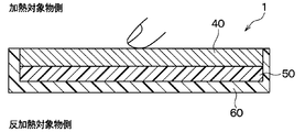
- FIG. 2 is a cross-sectional view of the heater device 1 of the present embodiment.
- the heater device 1 includes a heater housing 60, a heat insulating material 50, and a heater body 40.
- the heater housing 60 is made of a plastic resin such as PP or ABS.
- the heater housing 60 is a box-shaped member having an opening formed on one surface.
- the heat insulating material 50 and the heater body 40 are housed inside the heater housing portion 60.
- the heat insulating material 50 has high elasticity and high heat resistance, and is disposed at the bottom of the heater housing 60. One surface of the heat insulating material 50 is bonded to the bottom surface of the heater housing 60. The heat insulating material 50 suppresses the movement of the radiant heat radiated from the heater body 40 to the heater housing 60.
- the heater body 40 is disposed on the side opposite to the bottom side of the heater housing 60 of the heat insulating material 50. One surface of the heater body 40 is bonded to the heat insulating material 50, and a surface member 35 is disposed on the other surface of the heater body 40.
- the heater body 40 has a heat generating portion 20 described later, and radiates heat by the heat of the heat generating portion 20.
- the heater body 40 has a thickness of several tens of microns to 1 millimeter.
- FIG. 3 is a cross-sectional view of the heater body 40.
- the heater body 40 radiates radiant heat with the upper side in FIG. 3 as the heating target side, that is, the human body side.
- the heater body 40 includes the heat generating part 20 and the contact detection layer 30.
- the contact detection layer 30 is disposed on the heating object side of the heat generating part 20.
- the contact detection layer 30 includes a first insulating layer 31, a first conductive portion 34a, a second insulating layer 32, a second conductive portion 34b, and a surface member 35.
- the first insulating layer 31 and the second insulating layer 32 have high insulation properties. Moreover, the 1st insulating layer 31 and the 2nd insulating layer 32 have comprised the sheet form, respectively.
- the first conductive portion 34 a is disposed on the one surface side of the first insulating layer 31, and the second conductive portion 34 b is disposed on the one surface side of the second insulating layer 32.
- the first insulating layer 31 and the second insulating layer 32 are arranged so that the first conductive portion 34a and the second conductive portion 34b face each other with the air layer 2 interposed therebetween.
- the surface member 35 is disposed on the other surface side of the first insulating layer 31, that is, on the heating object side.
- the surface of the surface member 35 opposite to the first insulating layer 31, that is, the surface on the heating object side is a contact surface St that contacts an object.
- the surface of the surface member 35 on the first insulating layer 31 side is bonded to the first insulating layer 31.
- the surface member 35 is made of, for example, a film-like polyimide resin.
- the surface member 35 is provided not only for increasing the thermal resistance, but also for protecting the heater body 40 and improving the appearance.
- a fixing portion 33 is disposed on the outer edge portions of the first insulating layer 31 and the second insulating layer 32. Due to the fixing portion 33, a gap is provided between the first insulating layer 31 and the second insulating layer 32. That is, the air layer 2 is formed between the first insulating layer 31 and the second insulating layer 32.
- the contact detection layer 30 has a contact surface St that comes into contact with an object, and detects the contact of the object with the contact surface St.
- the gap between the first conductive portion 34a and the second conductive portion 34b is It becomes a non-conductive state.
- the first conductive portion 34a and the second conductive portion 34b are deformed so that the first conductive portion 34a and the second conductive portion 34b are in contact with each other, the first conductive portion 34a and the first conductive portion 34a
- the two conductive portions 34b are in a conductive state.
- the heat generating portion 20 has a sheet shape, and generates heat when energized to emit radiant heat.
- the heat generating unit 20 is provided integrally with the contact detection layer 30 on the side opposite to the contact surface St of the contact detection layer 30.
- the heat generating part 20 has the same configuration as that described in Patent Document 1. That is, the heat generating unit 20 includes a substrate unit, an electrode embedded in the substrate unit, and a plurality of heat generating units (none of which are shown).
- the electrode and the heat generating portion are electrically connected inside the substrate and are each formed in a film shape. Since the electrode and the heat generating part are formed in a film shape, the temperature of the heat generating part rapidly decreases when an object comes into contact with the heat generating part 20. For this reason, for example, when a human body touches the heat-emitting part 20, the thermal discomfort to a person can be reduced.
- the thickness of the heat generating portion 20 is thicker than the total thickness of the first insulating layer 31 and the second insulating layer 32, and the rigidity of the heat generating portion 20 is the first insulating layer 31. And higher than the sum of the second insulating layers 32.
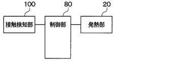
- FIG. 4 is a block diagram showing an electrical configuration of the heater device 1 according to the present embodiment.
- the heater device 1 includes a contact detection unit 100, a control unit 80, and a heat generation unit 20.
- the contact detection unit 100 determines whether the object is in contact with the contact detection layer 30 based on whether the first conductive unit 34a and the second conductive unit 34b that are arranged to face each other are in a conductive state or a non-conductive state. A signal that is detected electrically and indicates whether or not an object is in contact is output to the control unit 80.
- the control unit 80 is configured as a computer including a CPU, a RAM, a ROM, an I / O, and the like, and the CPU performs various processes according to a program stored in the ROM.
- control unit 80 When the contact detection unit 100 detects that an object has come into contact, the control unit 80 performs a control process to stop energization of the heat generating unit.
- FIG. 5 is a flowchart of this control process.
- the control unit 80 periodically performs the process shown in FIG.
- each control step in the flowchart of each drawing comprises the various function implementation
- step S100 the control unit 80 determines whether or not the contact of an object with the contact surface St is detected. Specifically, it is determined based on a signal input from the contact detection unit 100 whether or not contact of an object with the contact surface St has been detected.
- the control unit 80 determines that there is no contact of the object with the contact surface St, and in step S104, continues the energization to the heat generating unit 20 without stopping the heater output, and ends this process.
- the control unit 80 determines that there is an object contact with the contact surface St, and stops the heater output in step S102. Specifically, energization to the heat generating unit 20 is stopped, and this process is terminated.
- the heater device 1 is a heater device that radiates radiant heat, and includes the sheet-like heat generating portion 20 and the sheet-like contact detection layer 30.
- the heat generating part 20 generates heat by energization and radiates radiant heat.
- the contact detection layer 30 has a contact surface St that comes into contact with an object, and detects contact of the object with the contact surface St.
- the heat generating unit 20 is disposed on the side opposite to the contact surface of the contact detection layer 30.
- the heat generating unit 20 is disposed on the opposite side of the contact surface St of the contact detection layer 30, and the contact detection layer 30 directly detects the contact of the object with the contact surface St.
- a contact detection layer can be provided in the heat generating part without reducing accuracy.
- the contact detection layer 30 includes a sheet-like first insulating layer 31, a first conductive portion 34a formed on one surface of the first insulating layer 31, a sheet-like second insulating layer 32, and a second insulating layer. 32, a second conductive portion 34b formed on one surface.
- the first insulating layer 31 and the second insulating layer 32 are arranged such that the first conductive portion 34a and the second conductive portion 34b face each other with the air layer 2 in between.
- control unit 80 includes a contact detection unit 100 that detects contact of an object based on whether the first conductive unit 34 a and the second conductive unit 34 b are in a conductive state. When contact is detected, the power supply to the heat generating unit 20 is stopped, so that safety can be ensured.
- the thickness of the heat generating portion 20 is thicker than the total thickness of the first insulating layer 31 and the second insulating layer 32, and the rigidity of the heat generating portion 20 is the same as that of the first insulating layer 31 and the first insulating layer 31. Since it is higher than the sum of the two insulating layers 32, deformation of the heat generating portion 20 due to pressure when an object comes into contact can be suppressed, and detection accuracy of object contact can be further improved.
- one sheet-like first conductive portion 34a is formed on one surface of the first insulating layer 31, and one sheet-like second conductive portion 34b is a second insulating layer. 32 is formed on one surface.
- a plurality of sheet-like first conductive portions 34a are formed on one surface of the first insulating layer 31, and a plurality of sheet-like second conductive portions 34b are second. It is formed on one surface of the insulating layer 32.
- the heater device 1 of the present embodiment includes a plurality of spacers 36 that maintain the distance between the first conductive portion 34a and the second conductive portion 34b.
- the first insulating layer 31 and the second insulating layer 32 are arranged so that the first conductive portion 34a and the second conductive portion 34b face each other with the air layer 2 interposed therebetween.
- the spacer 36 has a cylindrical shape, and is made of, for example, acrylic resin.
- the spacer 36 forms the air layer 2 between the first insulating layer 31 and the second insulating layer 32.
- the spacer 36 is bonded between the first insulating layer 31 and the second insulating layer 32 using an adhesive.
- a heater device according to a third embodiment will be described with reference to FIG.
- the heater device 1 of this embodiment is different from the heater device 1 of the first embodiment in that it further includes a third insulating layer 21.
- the third insulating layer 21 is disposed so as to surround the entire heat generating portion 20. That is, the third insulating layer 21 is provided so as to surround in three directions, that is, the contact detection layer 30 side of the heat generating unit 20, the opposite side of the heat generating unit 20 on the contact detection layer 30 side, and the side surface side of the heat generating unit 20. Yes.
- the plate thickness of the third insulating layer 21 is thicker than the sum of the plate thickness of the first insulating layer 31 and the plate thickness of the second insulating layer 32, and the rigidity of the third insulating layer 21 is the first insulating layer. It is higher than the sum of the layer 31 and the second insulating layer 32.
- the plate thickness of the third insulating layer 21 on the contact detection layer 30 side of the heat generating portion 20 and the thickness of the third insulating layer 21 on the opposite side of the heat detection portion 20 on the contact detection layer 30 side is: It is thicker than the sum of the thickness of the first insulating layer 31 and the thickness of the second insulating layer 32. Further, the rigidity of the portion of the third insulating layer 21 on the side of the contact detection layer 30 of the heat generating portion 20 and the rigidity of the portion of the third insulating layer 21 on the side of the heat detecting portion 20 on the side of the contact detecting layer 30 are combined. The height is higher than the sum of the first insulating layer 31 and the second insulating layer 32.
- the heater device 1 includes a third insulating layer 21 disposed on the contact detection layer 30 side of the heat generating unit 20 and on the opposite side of the heat detection unit 20 on the contact detection layer 30 side.
- the plate thickness of the third insulating layer 21 is thicker than the total thickness of the plate thickness of the first insulating layer 31 and the plate thickness of the second insulating layer 32.
- the rigidity of the third insulating layer 21 is higher than that of the first insulating layer 31 and the second insulating layer 32 combined.
- the rigidity of the third insulating layer 21 is higher than that of the combination of the first insulating layer 31 and the second insulating layer 32. Therefore, the deformation of the heat generating part 20 due to the pressure when the object comes into contact is reduced. This can be suppressed, and the detection accuracy of the object contact can be further improved.
- the third insulating layer 21 is configured to be located on both the contact detection layer 30 side of the heat generating unit 20 and the side opposite to the contact detection layer 30 side of the heat generating unit 20.
- the third insulating layer 21 is configured to be positioned on at least one of the heat detection unit 20 on the side of the contact detection layer 30 and the heat generation unit 20 on the side opposite to the contact detection layer 30 are also permitted.
- the third insulating layer 21 may be configured to be located only on one of the heat detection unit 20 on the side of the contact detection layer 30 and the heat generation unit 20 on the side opposite to the contact detection layer 30 side.
- a heater device according to a fourth embodiment will be described with reference to FIG.
- a protrusion 70 that protrudes toward the heat insulating material 50 is further formed on the bottom surface of the heater housing 60. The point is different.
- the protrusion 70 is a surface in the heater housing 60 and is formed on a surface to which a load is applied due to the contact of the object when the object contacts the contact surface St. Specifically, the protruding portion 70 is formed on the bottom surface of the heater accommodating portion 60 so as to protrude toward the contact surface St.
- the load is distributed and transmitted to the contact detection layer 30 when a load is applied to the contact surface St by the user's finger. For this reason, in order to make the 1st electroconductive part 34a and the 2nd electroconductive part 34b a contact state, it is necessary to push the contact surface St with a big load. That is, the object detection accuracy is not good.
- the protrusion 70 is formed on the bottom surface of the heater housing 60 as in the present embodiment
- the load is concentrated on the protrusion 70. It is transmitted.
- the 1st electroconductive part 34a and the 2nd electroconductive part 34b can be made into a contact state with a comparatively small load. That is, the object detection accuracy can be further improved.
- the control unit 80 stops energization of the heat generating unit 20 when the first conductive unit 34a and the second conductive unit 34b are in a conductive state.
- the control unit 80 may reduce the amount of current supplied to the heat generating unit 20 when the first conductive unit 34a and the second conductive unit 34b are in a conductive state.
- the heater device 1 is installed on the lower surface of the steering column 14 so as to face the occupant 12.
- the heater device 1 can be installed on the surface of an instrument panel of a vehicle, a glove box of a vehicle, a seat back of the vehicle, or the like.
- the present invention is applied to a heater device configured such that when an object touches the heat generating portion, the temperature of the touched portion rapidly decreases.
- the thickness of the heat generating portion 20 is larger than the total thickness of the first insulating layer 31 and the second insulating layer 32.
- the rigidity of the heat generating portion 20 is higher than that of the combination of the first insulating layer 31 and the second insulating layer.
- the aspect in which the rigidity of the heat generating portion 20 is higher than that of the first insulating layer 31 and the second insulating layer 32 is not limited to this.
- the heat generating part 20 may have a rib, so that the rigidity of the heat generating part 20 may be higher than that of the first insulating layer 31 and the second insulating layer 32 combined.
- the rigidity of the heat generating part 20 is increased between the first insulating layer 31 and the second insulating layer 32. May be higher than combined.
- the thickness of the third insulating layer 21 is larger than the total thickness of the first insulating layer 31 and the second insulating layer 32.
- the rigidity of the third insulating layer 21 is higher than that of the combination of the first insulating layer 31 and the second insulating layer.
- the aspect in which the rigidity of the third insulating layer 21 is higher than that of the first insulating layer 31 and the second insulating layer 32 is not limited to this.
- the rigidity of the third insulating layer 21 may be higher than that of the first insulating layer 31 and the second insulating layer 32 combined.
- the rigidity of the third insulating layer 21 is increased between the first insulating layer 31 and the second insulating layer 31. It may be higher than the sum of the insulating layers 32.
- the contact of the object is detected according to the contact or non-contact of the first conductive portion 34a and the second conductive portion 34b.
- the method of detecting the contact of the object with the contact surface is not limited to this, and for example, a method of detecting the contact of the object with the contact surface by a capacitance method may be employed.
- An electrostatic capacitance detection sheet whose electrostatic capacitance changes due to the approach of an object is used instead of the first conductive portion 34a and the second conductive portion 34b.
- the capacitance detection sheet is a component of the contact detection layer.
- the heat generating portion 20 is disposed on the side opposite to the contact surface St of the capacitance detection sheet.
- the surface member 35 equivalent to that in the first embodiment may be provided or may not be provided.
- the sheet-like heat generating portion that generates heat by energization and emits radiant heat, and the contact surface that contacts the object, to the contact surface
- a sheet-like contact detection layer that detects contact of the object, and the heat generating portion is disposed on the opposite side of the contact surface of the contact detection layer.
- the heat generating part is disposed on the side opposite to the contact surface of the contact detection layer, and the contact detection layer directly detects the contact of the object with the contact surface, thereby reducing the object detection accuracy.
- a contact detection layer can be provided in the heat generating portion.
- the contact detection layer includes a sheet-like first insulating layer, a first conductive portion formed on one surface of the first insulating layer, a sheet-like second insulating layer, and a second insulation.
- a second conductive portion formed on one surface of the layer, the first insulating layer and the second insulating layer such that the first conductive portion and the second conductive portion face each other with the air layer (2) interposed therebetween. Is arranged.
- the first conductive part and the second conductive part are brought into contact with each other by the pressure when the object comes into contact, and the object contact is based on whether or not the first conductive part and the second conductive part are in a conductive state. Therefore, the contact of the object can be detected with a simple configuration.
- the contact detection unit that detects contact of an object based on whether or not the first conductive unit and the second conductive unit are in a conductive state, and the contact detection unit detects contact of the object.
- the heater device includes a control unit that stops energization of the heat generation unit or reduces the amount of power supply to the heat generation unit. According to this, when the contact of the object is detected by the contact detection unit 100, the control unit 80 stops the energization to the heat generating unit 20 or reduces the energization amount to the heat generating unit 20, and thus ensures safety. be able to.
- the rigidity of the heat generating portion is higher than that of the combination of the first insulating layer and the second insulating layer. According to this, since the rigidity of the heat generating part is higher than that of the combination of the first insulating layer and the second insulating layer, it is possible to suppress deformation of the heat generating part due to pressure when an object comes in contact with it, The detection accuracy of the object contact can be improved. Furthermore, the detection accuracy of the object contact can be further improved.
- the thickness of the heat generating portion is larger than the total thickness of the first insulating layer and the second insulating layer.
- the heater device includes the third insulating layer disposed on at least one of the contact detection layer side of the heat generating portion and the contact detection layer side of the heat generating portion, and the rigidity of the third insulating layer is The height is higher than the sum of the first insulating layer and the second insulating layer. According to this, the rigidity of the third insulating layer is higher than that of the combination of the first insulating layer and the second insulating layer, so that it is possible to suppress the deformation of the heat generating portion due to the pressure when the object comes into contact. This can improve the detection accuracy of the object contact.
- the thickness of the third insulating layer is larger than the total thickness of the first insulating layer and the second insulating layer.
- the heater device includes a spacer that is disposed between the first insulating layer and the second insulating layer and maintains a distance between the first insulating layer and the second insulating layer. For this reason, it is possible to prevent erroneous detection that an object is in contact with the object due to deformation due to its own weight or heat. Moreover, since the space
- the heater device includes a heater housing portion that houses the heat generating portion and the contact detection layer, and is a surface in the heater housing portion that is weighted by contact of an object when the object contacts the contact surface.
- a projecting surface having a projecting portion projecting to the contact surface side is formed on this surface.
- the heater device since the heater device includes a heat insulating material between the heat generating portion and the heater accommodating portion, it is possible to suppress the movement of heat from the heat generating portion to the heater accommodating portion.
- the contact detection layer can detect contact of an object with the contact surface by being deformed.
- the contact detection layer has two members, and the two members are in contact with each other, so that the contact detection layer detects contact of an object with the contact surface.
Landscapes
- Physics & Mathematics (AREA)
- Thermal Sciences (AREA)
- Engineering & Computer Science (AREA)
- Mechanical Engineering (AREA)
- Control Of Resistance Heating (AREA)
- Surface Heating Bodies (AREA)
- Air-Conditioning For Vehicles (AREA)
Abstract
Un dispositif de chauffage qui émet une chaleur rayonnante est pourvu d'une section de génération de chaleur (20) et d'une couche de détection de contact (30). La section de génération de chaleur est un élément de type feuille qui, lorsque l'électricité circule dans celle-ci, génère de la chaleur et émet la chaleur rayonnante. La couche de détection de contact est une couche de type feuille qui comporte une surface de contact (St) venant en contact avec un objet et qui détecte le contact de l'objet avec la surface de contact. La section de génération de chaleur est disposée sur le côté de la couche de détection de contact opposée à la surface de contact.
Priority Applications (1)
| Application Number | Priority Date | Filing Date | Title |
|---|---|---|---|
| JP2017556433A JP6432696B2 (ja) | 2015-12-17 | 2016-11-17 | ヒータ装置 |
Applications Claiming Priority (2)
| Application Number | Priority Date | Filing Date | Title |
|---|---|---|---|
| JP2015-246526 | 2015-12-17 | ||
| JP2015246526 | 2015-12-17 |
Publications (1)
| Publication Number | Publication Date |
|---|---|
| WO2017104343A1 true WO2017104343A1 (fr) | 2017-06-22 |
Family
ID=59056090
Family Applications (1)
| Application Number | Title | Priority Date | Filing Date |
|---|---|---|---|
| PCT/JP2016/084093 Ceased WO2017104343A1 (fr) | 2015-12-17 | 2016-11-17 | Dispositif de chauffage |
Country Status (2)
| Country | Link |
|---|---|
| JP (1) | JP6432696B2 (fr) |
| WO (1) | WO2017104343A1 (fr) |
Cited By (1)
| Publication number | Priority date | Publication date | Assignee | Title |
|---|---|---|---|---|
| US20220264702A1 (en) * | 2019-11-18 | 2022-08-18 | Denso Corporation | Heater device |
Citations (9)
| Publication number | Priority date | Publication date | Assignee | Title |
|---|---|---|---|---|
| EP0873903A2 (fr) * | 1997-04-24 | 1998-10-28 | Volkswagen Aktiengesellschaft | Dispositif à palpeur de pression en feuille pour détecter l'occupation d'un siège de véhicule |
| JP2003533311A (ja) * | 2000-05-17 | 2003-11-11 | アイ.イー.イー.インターナショナル エレクトロニクス アンド エンジニアリング エス.エイ アール.エル. | センサー・発熱体の組合せ体 |
| JP2004175291A (ja) * | 2002-11-28 | 2004-06-24 | Aisin Seiki Co Ltd | 着座センサ |
| JP2013178185A (ja) * | 2012-02-29 | 2013-09-09 | Nissan Motor Co Ltd | 布状圧力センサーヒーター |
| JP2014190674A (ja) * | 2013-03-28 | 2014-10-06 | Denso Corp | ヒータ装置 |
| JP2015016703A (ja) * | 2013-07-08 | 2015-01-29 | 株式会社デンソー | 輻射ヒータ装置 |
| WO2015186329A1 (fr) * | 2014-06-03 | 2015-12-10 | 株式会社デンソー | Dispositif de commande de réglage de température |
| WO2016013168A1 (fr) * | 2014-07-25 | 2016-01-28 | 株式会社デンソー | Dispositif de chauffage à rayonnement |
| WO2016117375A1 (fr) * | 2015-01-22 | 2016-07-28 | 株式会社デンソー | Dispositif de chauffage |
Family Cites Families (3)
| Publication number | Priority date | Publication date | Assignee | Title |
|---|---|---|---|---|
| JPH076024U (ja) * | 1993-06-25 | 1995-01-27 | 近畿車輌株式会社 | 車両の暖房装置 |
| JP2010277809A (ja) * | 2009-05-28 | 2010-12-09 | Sumitomo Electric Ind Ltd | 加熱ヒータおよびそれを備えた装置 |
| JP2014089798A (ja) * | 2011-02-23 | 2014-05-15 | Panasonic Corp | 面状発熱体 |
-
2016
- 2016-11-17 WO PCT/JP2016/084093 patent/WO2017104343A1/fr not_active Ceased
- 2016-11-17 JP JP2017556433A patent/JP6432696B2/ja active Active
Patent Citations (9)
| Publication number | Priority date | Publication date | Assignee | Title |
|---|---|---|---|---|
| EP0873903A2 (fr) * | 1997-04-24 | 1998-10-28 | Volkswagen Aktiengesellschaft | Dispositif à palpeur de pression en feuille pour détecter l'occupation d'un siège de véhicule |
| JP2003533311A (ja) * | 2000-05-17 | 2003-11-11 | アイ.イー.イー.インターナショナル エレクトロニクス アンド エンジニアリング エス.エイ アール.エル. | センサー・発熱体の組合せ体 |
| JP2004175291A (ja) * | 2002-11-28 | 2004-06-24 | Aisin Seiki Co Ltd | 着座センサ |
| JP2013178185A (ja) * | 2012-02-29 | 2013-09-09 | Nissan Motor Co Ltd | 布状圧力センサーヒーター |
| JP2014190674A (ja) * | 2013-03-28 | 2014-10-06 | Denso Corp | ヒータ装置 |
| JP2015016703A (ja) * | 2013-07-08 | 2015-01-29 | 株式会社デンソー | 輻射ヒータ装置 |
| WO2015186329A1 (fr) * | 2014-06-03 | 2015-12-10 | 株式会社デンソー | Dispositif de commande de réglage de température |
| WO2016013168A1 (fr) * | 2014-07-25 | 2016-01-28 | 株式会社デンソー | Dispositif de chauffage à rayonnement |
| WO2016117375A1 (fr) * | 2015-01-22 | 2016-07-28 | 株式会社デンソー | Dispositif de chauffage |
Cited By (2)
| Publication number | Priority date | Publication date | Assignee | Title |
|---|---|---|---|---|
| US20220264702A1 (en) * | 2019-11-18 | 2022-08-18 | Denso Corporation | Heater device |
| US12543246B2 (en) * | 2019-11-18 | 2026-02-03 | Denso Corporation | Heater device |
Also Published As
| Publication number | Publication date |
|---|---|
| JPWO2017104343A1 (ja) | 2018-03-22 |
| JP6432696B2 (ja) | 2018-12-05 |
Similar Documents
| Publication | Publication Date | Title |
|---|---|---|
| JP6432691B2 (ja) | ヒータ装置 | |
| CN105075390B (zh) | 加热器装置 | |
| JP6376286B2 (ja) | ヒータ装置 | |
| JP6447245B2 (ja) | 輻射ヒータ装置 | |
| US11497084B2 (en) | Heater device | |
| CN111886147B (zh) | 加热器装置 | |
| JP5568613B2 (ja) | シートヒーター | |
| US10913328B2 (en) | Heater device | |
| WO2020075473A1 (fr) | Dispositif de chauffage | |
| WO2020195900A1 (fr) | Dispositif de chauffage | |
| JP6432696B2 (ja) | ヒータ装置 | |
| US20210331203A1 (en) | Electrostatic transducer and electrostatic transducer unit | |
| WO2013005432A1 (fr) | Structure de détection d'opérations externes | |
| JP6296175B2 (ja) | ヒータ装置 | |
| US8143907B2 (en) | Capacitive occupant sensor | |
| WO2018150769A1 (fr) | Appareil de chauffage | |
| WO2020195901A1 (fr) | Dispositif de chauffage | |
| WO2016013168A1 (fr) | Dispositif de chauffage à rayonnement | |
| JP6528654B2 (ja) | ヒータシステム | |
| JP2007035334A (ja) | 静電容量式タッチスイッチ | |
| WO2019045104A1 (fr) | Appareil de chauffage | |
| JP6669271B2 (ja) | 輻射ヒータ装置 | |
| JP2025009262A (ja) | 車両用内装部品及び車両の乗員報知システム |
Legal Events
| Date | Code | Title | Description |
|---|---|---|---|
| 121 | Ep: the epo has been informed by wipo that ep was designated in this application |
Ref document number: 16875327 Country of ref document: EP Kind code of ref document: A1 |
|
| ENP | Entry into the national phase |
Ref document number: 2017556433 Country of ref document: JP Kind code of ref document: A |
|
| NENP | Non-entry into the national phase |
Ref country code: DE |
|
| 122 | Ep: pct application non-entry in european phase |
Ref document number: 16875327 Country of ref document: EP Kind code of ref document: A1 |