WO2017104559A1 - 燃料噴射制御装置 - Google Patents
燃料噴射制御装置 Download PDFInfo
- Publication number
- WO2017104559A1 WO2017104559A1 PCT/JP2016/086689 JP2016086689W WO2017104559A1 WO 2017104559 A1 WO2017104559 A1 WO 2017104559A1 JP 2016086689 W JP2016086689 W JP 2016086689W WO 2017104559 A1 WO2017104559 A1 WO 2017104559A1
- Authority
- WO
- WIPO (PCT)
- Prior art keywords
- injection
- acquisition unit
- oxygen concentration
- injection rate
- control
- Prior art date
- Legal status (The legal status is an assumption and is not a legal conclusion. Google has not performed a legal analysis and makes no representation as to the accuracy of the status listed.)
- Ceased
Links
Images







Classifications
-
- F—MECHANICAL ENGINEERING; LIGHTING; HEATING; WEAPONS; BLASTING
- F02—COMBUSTION ENGINES; HOT-GAS OR COMBUSTION-PRODUCT ENGINE PLANTS
- F02D—CONTROLLING COMBUSTION ENGINES
- F02D41/00—Electrical control of supply of combustible mixture or its constituents
- F02D41/02—Circuit arrangements for generating control signals
- F02D41/04—Introducing corrections for particular operating conditions
-
- F—MECHANICAL ENGINEERING; LIGHTING; HEATING; WEAPONS; BLASTING
- F02—COMBUSTION ENGINES; HOT-GAS OR COMBUSTION-PRODUCT ENGINE PLANTS
- F02D—CONTROLLING COMBUSTION ENGINES
- F02D41/00—Electrical control of supply of combustible mixture or its constituents
- F02D41/30—Controlling fuel injection
- F02D41/38—Controlling fuel injection of the high pressure type
-
- F—MECHANICAL ENGINEERING; LIGHTING; HEATING; WEAPONS; BLASTING
- F02—COMBUSTION ENGINES; HOT-GAS OR COMBUSTION-PRODUCT ENGINE PLANTS
- F02D—CONTROLLING COMBUSTION ENGINES
- F02D45/00—Electrical control not provided for in groups F02D41/00 - F02D43/00
Definitions
- the present disclosure relates to a fuel injection control device that controls fuel injection into a combustion chamber of an internal combustion engine by a fuel injection valve having a variable injection rate waveform.
- Patent Document 1 discloses an internal combustion engine that includes two pressure accumulators and is capable of boot-type injection that gradually increases the injection rate in order to suppress noise. In order to reduce smoke in a state where the warm-up is insufficient and it is difficult to burn, control is disclosed in which the injection pressure of the boot portion is increased to promote combustion.
- the present disclosure has been made in view of the above-described problems, and an object of the present disclosure is to provide a fuel injection control device that can improve the exhaust gas and keep the combustion noise small regardless of the ease of combustion of the fuel in the cylinder.
- a first aspect of the present disclosure includes an index acquisition unit that acquires an index related to flammability in a cylinder, and a control unit that controls fuel injection using a plurality of injection rate waveforms. And the control unit compares the index acquired by the index acquisition unit with a predetermined threshold and, as a result, determines that it is easy to burn, without intermittent injection among a plurality of injection rate waveforms.
- This is a fuel injection control device that performs control so as to inject a rising injection rate waveform in which the injection rate gradually increases with respect to the elapsed time.
- the injection is controlled so that the injection rate increases gradually with respect to the elapsed time without intermittent injection. As a result, even in a flammable state, the heat generation rate gradually increases, so that combustion noise can be reduced while suppressing NOx.
- a second aspect of the present disclosure includes an index acquisition unit that acquires an index related to the flammability in a cylinder, and a control unit that controls fuel injection using a plurality of injection rate waveforms.
- the control unit compares the index acquired by the index acquisition unit with a predetermined threshold, and determines that it is difficult to burn. It is a fuel injection control device that controls to inject with a multistage injection rate waveform in which the peak of the injection rate of each stage gradually increases with time.
- the injection when the inside of the cylinder is difficult to burn, the injection is multistaged, and the injection is performed with a multistage injection rate waveform in which the peak of the injection rate of each stage gradually rises with respect to the elapsed time. Be controlled.
- the increase in the heat generation rate is moderate even if the injection is multistaged, so that the combustion noise can be reduced while suppressing NOx.
- the rate of change of the injection rate is increased by increasing the number of stages, the time during which the sheet stop is generated is shortened, and the occurrence of smoke can be suppressed.
- the drawing It is a figure which shows the outline
- the fuel injection control device is applied to a multi-cylinder diesel engine equipped with a common rail fuel injection device.
- the engine 10 shown in FIG. 1 is mounted on a vehicle as an in-vehicle main engine, and is a four-cycle engine including intake, compression, expansion, and exhaust strokes.
- an air flow meter 12 that detects an intake air amount
- an intercooler 13 that cools intake air supercharged by a turbocharger 16
- a throttle valve device in order from the upstream side. 14 is provided.
- the throttle valve device 14 adjusts the opening degree of the throttle valve 14a by an actuator such as a DC motor.
- a combustion chamber 10 a of each cylinder of the engine 10 is connected to the downstream side of the throttle valve device 14 in the intake passage 11 via a surge tank 15.
- the combustion chamber 10 a is partitioned by a cylinder 10 b and a piston 17 of the engine 10.
- the engine 10 is provided with a fuel injection valve 18 having a tip projecting into the combustion chamber 10a.
- High pressure fuel specifically light oil, is supplied to the fuel injection valve 18 from a common rail 19 serving as a pressure accumulator. Fuel is pumped from the fuel pump 20 to the common rail 19. In FIG. 1, only one cylinder is shown.
- the fuel injection valve 18 includes a needle and a body in which a plurality of circular injection holes for injecting fuel are formed at the tip, and the needle is accommodated therein. Between the inner surface of the body and the outer surface of the needle, an annular fuel passage that extends in the axial direction of the body and through which the fuel supplied from the common rail 19 passes is formed. A seating surface on which the tip of the needle is seated is formed on the inner surface of the body tip. In this configuration, when the needle is seated on the seating surface, the gap between the fuel passage and the injection hole is blocked, and fuel injection is stopped. On the other hand, the fuel passage and the injection hole are communicated with each other by separating the needle from the seating surface by the energization operation. As a result, the fuel in the fuel passage is directly supplied from the injection hole to the combustion chamber 10a.
- the fuel injection valve 18 is configured to be able to variably control the injection rate waveform.
- the injection rate waveform is a waveform showing a change in the injection rate over time.
- the fuel injection valve 18 is configured to freely control the lift amount of the needle so as to variably control the injection rate waveform.
- the fuel injection valve 18 adjusts the area of the fuel flow path by an actuator having a piezo element and injects fuel.
- the fuel injection valve can change the fuel injection rate waveform.
- the injection rate in the main injection can be made different over time.
- the actuator of the fuel injection valve 18 includes, for example, a piezo stack.
- the piezo stack is a stacked body in which layers called PZT (PbZrTiO 3) and thin electrode layers are alternately stacked, and expands and contracts by applying a voltage due to the reverse piezoelectric effect which is a characteristic of the piezo element.
- the actuator uses the displacement of the piezo stack to control the position of the needle.
- the needle when no voltage is applied to the piezo stack, the needle is closed and fuel injection is not performed.
- a voltage is applied to the piezo stack, the piezo stack expands, and with the expansion as a power, the needle is pushed up and fuel injection is started.
- the voltage applied to the piezo stack is turned off, it discharges and the piezo stack contracts. As a result, the needle is pushed down and fuel injection stops.
- the voltage supplied to the actuator By controlling the voltage supplied to the actuator, the amount of expansion of the piezo stack can be controlled. Therefore, by controlling the voltage, the valve opening speed of the needle can be adjusted in a plurality of stages, so that the injection seal can be freely controlled.
- the intake port and the exhaust port of each cylinder of the engine 10 are opened and closed by the intake valve 21 and the exhaust valve 22, respectively.
- the intake air cooled by the intercooler 13 by opening the intake valve 21 and the external EGR gas are introduced into the combustion chamber 10a.
- the fuel injection valve 18 into the combustion chamber 10a with intake air or the like introduced the fuel self-ignites due to compression of the combustion chamber 10a, and energy is generated by combustion. This energy is taken out as rotational energy of the crankshaft 23 of the engine 10 via the piston 17.
- the gas used for combustion is discharged as exhaust into the exhaust passage 24 by opening the exhaust valve 22.
- a crank angle sensor 25 that detects the rotation angle of the crankshaft 23 is provided in the vicinity of the crankshaft 23.
- the vehicle is provided with a turbocharger 16.
- the turbocharger 16 includes an intake air compressor 16a provided in the intake passage 11, an exhaust turbine 16b provided in the exhaust passage 24, and a rotating shaft 16c that connects these. Specifically, the exhaust turbine 16b is rotated by the energy of the exhaust gas flowing through the exhaust passage 24, and the rotational energy is transmitted to the intake compressor 16a via the rotary shaft 16c, and the intake air is compressed by the intake compressor 16a. That is, the intake air is supercharged by the turbocharger 16.
- the turbocharger 16 can adjust the supercharging pressure of intake air by an energization operation.
- a purification device 26 for purifying exhaust gas is provided on the downstream side of the turbocharger 16.
- a part of the exhaust discharged to the exhaust passage 24 is returned to the intake passage 11 via the EGR passage 27.
- the upstream side of the exhaust turbine 16 b in the exhaust passage 24 is connected to the surge tank 15 via the EGR passage 27.
- An EGR valve device 28 is provided in the EGR passage 27.
- the EGR valve device 28 adjusts the opening degree of the EGR valve 28a by an actuator such as a DC motor.
- a part of the exhaust discharged to the exhaust passage 24 is cooled by the EGR cooler 29 and then supplied to the surge tank 15 as external EGR gas.
- the ECU30 which is an electronic control apparatus which makes an engine system a control object runs the program memorize
- the ECU includes at least one arithmetic processing unit (CPU) and a storage medium that stores programs and data.
- the ECU is realized, for example, by a microcomputer having a storage medium readable by a computer (hereinafter also referred to as “microcomputer”).
- the storage medium is a non-transitional physical storage medium that stores a computer-readable program and data in a non-temporary manner.
- the memory is realized by a semiconductor memory or a magnetic disk.
- the ECU 30 includes an intake pressure sensor 31, an intake temperature sensor 32, an exhaust temperature sensor 33, an in-cylinder pressure sensor 34, an oxygen concentration sensor 38, a fuel pressure sensor 35, a water temperature sensor 36, an accelerator sensor 37, an air flow meter 12, and a crank angle sensor 25.
- the detected value is input.
- the intake pressure sensor 31 detects the gas pressure in the surge tank 15.
- the intake air temperature sensor 32 detects the gas temperature in the surge tank 15.
- the exhaust temperature sensor 33 detects the temperature of the exhaust discharged from the combustion chamber 10a.
- the in-cylinder pressure sensor 34 detects an in-cylinder pressure that is a pressure in the combustion chamber 10a.
- the oxygen concentration sensor 38 is attached to the intake passage 11 and detects the oxygen concentration in the intake air.
- the intake air to be detected is a mixture of fresh air and EGR gas.
- the fuel pressure sensor 35 detects the fuel pressure in the common rail 19.
- the water temperature sensor 36 detects the cooling water temperature of the engine 10.
- the crank angle sensor 25 detects the engine speed that is the rotational speed of the crankshaft 23 that is rotationally driven by the piston 17 and that is the rotational speed of the crankshaft 23 per unit time.
- the accelerator sensor 37 detects the accelerator operation amount of the accelerator operation member of the driver, and specifically detects the depression amount of the accelerator pedal.
- the ECU 30 includes a fuel injection control of the fuel injection valve 18, a drive control of the fuel pump 20, a drive control of the EGR valve device 28, and a supercharging pressure control by the turbocharger 16 based on detection values of various sensors. Combustion control is performed. With these controls, the combustion state in the engine 10 included in the combustion system is controlled to a desired state. Therefore, the ECU 30 functions as a control unit that controls the injection rate.
- the injection mode there are two injection modes, a first injection mode and a second injection mode, and the switching control is performed at a predetermined timing.
- the first injection mode is indicated by a solid line
- the second injection mode is indicated by a broken line.
- the first injection mode has a multistage injection rate waveform in which the injection is multistaged and the peak of the injection rate of each stage gradually increases with respect to the elapsed time.
- the first injection mode has an injection rate waveform in which injection is performed in multiple stages and injection at each stage is performed in a predetermined amount and timing.
- the injection is made into three stages, the first two stages are triangular, and the final stage is trapezoidal.
- the peak of each stage is the smallest in the first stage and gradually increases.
- the second injection mode has a rising injection rate waveform in which the injection rate gradually increases with respect to the elapsed time without intermittent injection.
- the second injection mode has a so-called boot shape, and has a waveform in which the injection rate does not decrease until the maximum injection rate is reached from a state where the inclination of the initial injection rate is large to a state where the inclination is small.
- the waveform gradually rises regardless of the injection rate mode.
- ignition is easy, so the ignition delay is short, and the heat generation rate has a waveform similar to the injection rate shape.
- the heat generation rate becomes a waveform having a swell similar to the injection rate waveform.
- the heat generation rate can be gradually increased even in the first injection mode, so that combustion noise and NOx can be suppressed.
- the first injection mode has a higher valve opening speed than the second injection mode, it is possible to perform injection with less forcible seat choke, so that it is possible to form a spray that is easily mixed with air.
- the first injection mode can also suppress smoke.
- the time during which seat choke is generated is shorter than in the second injection mode, so smoke can be suppressed.
- the seat choke is also called a seat choke, and is a gap between the needle and the valve seat formed when the needle is separated from the valve seat.
- the injection mode is switched using the warm-up EGR, the high load EGR, and the supercharging pressure as indexes, and low noise and low emission according to the operation state can be achieved.
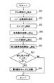
- the switching control shown in FIG. 5 is a control that is repeatedly performed when the injection is controlled in the first injection mode.
- step S11 the accelerator opening degree ⁇ ac is detected, and the process proceeds to step S12.
- the ECU 30 acquires the accelerator opening degree ⁇ ac from the accelerator sensor 37.
- step S12 the engine speed Ne is detected, and the process proceeds to step S13.
- the ECU 30 acquires the engine speed Ne from the crank angle sensor 25.
- step S13 the water temperature Tw is detected, and the process proceeds to step S14.
- the ECU 30 acquires the water temperature Tw from the water temperature sensor 36.
- step S14 the warm-up determination water temperature threshold value Tth is read, and the process proceeds to step S15.
- the warm-up determination water temperature threshold value Tth is a value stored in advance in the storage medium.
- the warm-up determination water temperature threshold Tth is a predetermined constant value or a numerical value based on the detected accelerator opening ⁇ ac and the engine speed Ne. In the latter case, for example, the warm-up determination water temperature threshold Tth is determined using the map of FIG.
- step S15 it is determined whether or not the engine is warming up. If the engine is warming up, the process proceeds to step S16. If the engine is not warming up, the flow ends. Whether or not the engine is warming up is determined by comparing the warm-up determination water temperature threshold Tth and the water temperature Tw, and when the water temperature Tw is smaller than the warm-up determination water temperature threshold Tth. In other words, when the water temperature Tw is smaller than the predetermined warm-up determination water temperature threshold value Tth, the water temperature is still low, and the system is warming up.
- step S16 the EGR amount is adjusted based on the water temperature Tw, and the process proceeds to step S17. Specifically, the colder the water temperature Tw, the easier the inside of the cylinder is to cool and the more difficult it is to burn. Therefore, the EGR valve opening ⁇ EGR is adjusted to reduce the EGR amount.
- step S17 the intake oxygen concentration rO2 is detected, and the process proceeds to step S18.
- the ECU 30 acquires the intake oxygen concentration r O2 from the oxygen concentration sensor 38. Therefore, the ECU 30 functions as an oxygen concentration acquisition unit that acquires the oxygen concentration of the intake air.
- step S18 the intake oxygen concentration threshold value rth is read, and the process proceeds to step S19.
- the intake oxygen concentration threshold value rth is a value stored in advance in the storage medium.
- the intake oxygen concentration threshold value rth is a predetermined constant value or a numerical value based on the detected accelerator opening ⁇ ac and engine speed Ne. In the latter case, the intake oxygen concentration threshold rth is determined using, for example, the map of FIG.
- step S19 it is determined whether or not it is easy to burn. If it is easy to burn, the process proceeds to step S110, and if it is difficult to burn, this flow ends. Or likely or not burn compares the intake oxygen concentration r O2 and intake oxygen concentration threshold rth, when the intake oxygen concentration r O2 is the intake oxygen concentration threshold rth or more, it is determined that easily burn the oxygen is more.
- step S110 the injection mode is switched to the second injection mode, and this flow ends.
- the injection mode is switched from the first injection mode to the second injection mode.
- the second injection mode when it is easy to burn, generation of NOx can be suppressed and noise can be suppressed.
- the injection in the case of a flammable state, the injection is controlled so that the injection is performed in the second injection mode that is a rising injection rate waveform in which the injection rate gradually increases with respect to the elapsed time without intermittent injection. .
- the heat generation rate gradually increases even in a flammable state, so that combustion noise can be reduced while suppressing NOx.
- the oxygen concentration is lower than the predetermined oxygen concentration, by controlling to the first injection mode, which is another injection mode, even when the oxygen concentration is low and non-flammable, NOx, noise and smoke are reduced as described above. Can be suppressed.
- the ease of burning in the cylinder is determined when the engine is warming up, and the engine is switched to the second injection mode when the engine is warming up and combustible. If the engine is warming up, the first injection mode is usually prioritized in order to complete the warming up, but if it is flammable, the second injection is used to compensate for the disadvantage of increased combustion noise in the first injection mode. Implement the mode. This makes it possible to suppress combustion noise when it is easy to burn during warm-up.
- the oxygen concentration is used as an index of the flammability, and when it is determined that the flammability is easy as a result of comparing the index acquired by the index acquisition unit with a predetermined threshold, the second injection mode. It has been switched to.
- the oxygen concentration as an index of flammability, it is possible to accurately determine flammability and switch to the second injection mode.
- the present embodiment is characterized in that the injection mode is switched in consideration of not only the oxygen concentration but also the supercharging amount.
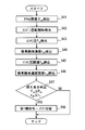
- the switching control shown in FIG. 8 is a control that is repeatedly performed when the injection is controlled in the first injection mode.
- step S21 the accelerator opening degree ⁇ ac is detected as in step S11, and the process proceeds to step S22.
- step S22 as in step S12, the engine speed Ne is detected, and the process proceeds to step S23.
- step S23 the intake manifold pressure Pim is detected, and the process proceeds to step S24.
- the ECU 30 acquires the intake manifold pressure Pim that is the in-cylinder pressure from the in-cylinder pressure sensor 34.
- the intake manifold pressure Pim is correlated with the supercharging amount. In this control, the intake manifold pressure Pim is used instead of the supercharging amount. Therefore, the ECU 30 functions as a supercharging amount acquisition unit that acquires the supercharging amount.
- step S24 as in step S16, the intake oxygen concentration rO2 is detected, and the process proceeds to step S25.
- the intake manifold pressure threshold Pth is read, and the process proceeds to step S26.
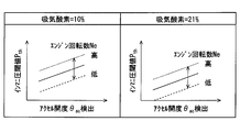
- the intake manifold pressure threshold Pth is a predetermined constant value or a numerical value based on the detected accelerator opening degree ⁇ ac, engine speed Ne, and intake manifold pressure threshold Pth. In the latter case, the intake manifold pressure threshold Pth is determined using, for example, a map for each intake oxygen in FIG. 9, that is, a three-dimensional map. In FIG. 9, two intake air concentrations are shown as an example, but the storage medium stores the relationship between the intake manifold pressure threshold Pth and the accelerator opening ⁇ ac for a plurality of intake air concentrations.
- step S26 the intake oxygen concentration threshold rth is read, and the process proceeds to step S27.
- the intake oxygen concentration threshold rth is a predetermined constant value or a numerical value based on the detected accelerator opening ⁇ ac, engine speed Ne, and intake manifold pressure threshold Pth.
- the intake oxygen concentration threshold value rth is determined using a map for each intake manifold pressure in FIG. 10, that is, a three-dimensional map. In FIG. 10, two intake manifold pressures are shown as an example, but the relationship between the intake oxygen concentration threshold rth and the accelerator opening ⁇ ac is stored in the storage medium for a plurality of intake manifold pressures.
- step S27 it is determined whether or not it is easy to burn. If it is easy to burn, the process proceeds to step S28, and if it is difficult to burn, this flow ends. Whether easy or not burn, compares the intake oxygen concentration r O2 and intake oxygen concentration threshold rth, and the intake oxygen concentration r O2 intake oxygen concentration threshold rth or more, and compared with the intake manifold pressure Pim and the intake manifold pressure threshold value Pth When the intake manifold pressure Pim is equal to or higher than the intake manifold pressure threshold Pth, it is determined that the combustion is easy. In step S29, the injection mode is switched to the second injection mode, and this flow ends.
- the injection mode is switched from the first injection mode to the second injection mode.
- the supercharging pressure which is the intake manifold pressure Pim is high, it is a case of a high load, and when it is easy to burn and is a high load, it is switched to the second injection mode.
- FIG. 10 there is a correlation between the intake manifold pressure Pim and the intake oxygen concentration threshold value rth, and the intake oxygen concentration threshold value rth decreases as the intake manifold pressure Pim increases.
- the combustion noise can be reduced while improving the exhaust gas by switching to the second injection mode at an appropriate timing.
- the present embodiment is characterized in that the second injection mode is switched to the first injection mode.
- the second injection mode is normally implemented, and the second injection mode is switched to the first injection mode by the switching control shown in FIG.
- the switching control shown in FIG. 11 is a control that is repeatedly performed when the injection is controlled in the second injection mode.
- the switching control of this embodiment is similar to the switching control of FIG. 5 of the first embodiment described above. Steps S35, S38, and S39 are different, and the other steps S31 to S34, step S36, and step S37 are different. Is the same process.
- step S31 the accelerator opening degree ⁇ ac is detected, and the process proceeds to step S32.
- step S32 the engine speed Ne is detected, and the process proceeds to step S33.
- step S33 the water temperature Tw is detected, and the process proceeds to step S34.
- step S34 the warm-up determination water temperature threshold value Tth is read, and the process proceeds to step S35.
- step S35 it is determined whether or not the engine is warming up. If the engine is not warming up, the process proceeds to step S36. If the engine is warming up, the flow ends.
- step S36 the EGR amount is adjusted based on the water temperature Tw, and the process proceeds to step S37. Specifically, the colder the water temperature Tw, the easier the inside of the cylinder is to cool and the more difficult it is to burn. Therefore, the EGR valve opening ⁇ EGR is adjusted to reduce the EGR amount.
- step S37 the intake oxygen concentration rO2 is detected, and the process proceeds to step S38.
- step S38 the intake oxygen concentration threshold value rth is read, and the process proceeds to step S39.
- step S39 it is determined whether or not it is easy to burn. If it is difficult to burn, the process proceeds to step S310, and if it is easy to burn, this flow ends. Whether easy or not burn, compares the intake oxygen concentration r O2 and intake oxygen concentration threshold rth, when the intake oxygen concentration r O2 is equal to or less than the intake oxygen concentration threshold rth, it is determined that hardly burning because less oxygen .
- step S310 the injection mode is switched to the first injection mode, and this flow ends.
- the injection when the oxygen concentration is equal to or lower than the predetermined oxygen concentration, the injection is multistage, and the first injection is an injection rate waveform in which the peak of the injection rate of each stage gradually increases with respect to the elapsed time.
- Control to inject in mode Specifically, when it is not warming up and it is difficult to burn, the injection mode is switched from the second injection mode to the first injection mode.
- the first injection mode when it is difficult to burn, the generation of smoke can be suppressed, and the generation of NOx and noise can also be suppressed. Therefore, the disadvantage of continuing the second injection mode can be compensated by switching to the first injection mode.
- this embodiment is characterized in that the second injection mode is switched to the first injection mode.
- the second injection mode is normally performed, and the second injection mode is switched to the first injection mode by the switching control shown in FIG.
- the switching control shown in FIG. 12 is a control that is repeatedly performed when the injection is controlled in the second injection mode.
- the switching control of this embodiment is similar to the switching control of FIG. 8 of the second embodiment described above. Steps S47 and S48 are different, and the other steps S41 to S46 are the same processing.
- step S41 the accelerator opening degree ⁇ ac is detected, and the process proceeds to step S42.
- step S42 the engine speed Ne is detected, and the process proceeds to step S43.
- step S43 the intake manifold pressure Pim is detected, and the process proceeds to step S44.
- step S44 the intake oxygen concentration rO2 is detected, and the process proceeds to step S45.
- step S45 the intake manifold pressure threshold value Pth is read, and the process proceeds to step S46.
- step S46 the intake oxygen concentration threshold value rth is read, and the process proceeds to step S47.
- step S47 it is determined whether or not it is difficult to burn. If it is difficult to burn, the process proceeds to step S48, and if it is easy to burn, this flow ends. Whether hard burned, compared to intake oxygen concentration r O2 intake oxygen compares the density threshold rth, intake oxygen concentration r O2 is below the intake oxygen concentration threshold rth, and the intake manifold pressure Pim and the intake manifold pressure threshold value Pth When the intake manifold pressure Pim is equal to or lower than the intake manifold pressure threshold Pth, it is determined that it is difficult to burn. In step S49, the injection mode is switched to the first injection mode, and this flow ends.
- control is performed so that the injection is performed in the first injection mode. If it is determined that hardly burned from the intake oxygen concentration r O2 and intake manifold pressure Pim, the injection mode is spatula switched from the second injection mode to the first injection mode. As described above, in the first injection mode, when it is difficult to burn, the generation of smoke can be suppressed, and the generation of NOx and noise can also be suppressed. Therefore, the disadvantage of continuing the second injection mode can be compensated by switching to the first injection mode.
- the present embodiment is characterized by switching from the first injection mode to the second injection mode.
- the first injection mode is normally performed, and the first injection mode is switched to the second injection mode by the switching control shown in FIG.
- the switching control shown in FIG. 13 is a control that is repeatedly performed when the injection is controlled in the first injection mode.
- the switching control of the present embodiment is similar to the switching control of FIG. 5 of the first embodiment described above, step S54 and step S55 are different, and the other steps S51 to S53 and step S56 are the same processing.
- step S51 the accelerator opening degree ⁇ ac is detected, and the process proceeds to step S52.
- step S52 the engine speed Ne is detected, and the process proceeds to step S53.
- step S53 the water temperature Tw is detected, and the process proceeds to step S54. Therefore, ECU30 functions as a water temperature acquisition part which acquires the engine coolant temperature.
- step S54 the flammability determination water temperature threshold value Tth0 is read, and the process proceeds to step S55.
- the flammability determination water temperature threshold value Tth0 is a value stored in advance in the storage medium.
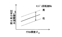
- the flammability determination water temperature threshold value Tth0 is a predetermined constant value or a numerical value based on the detected accelerator opening ⁇ ac and engine speed Ne. In the latter case, for example, the flammability determination water temperature threshold Tth0 is determined using the map of FIG.
- step S55 it is determined whether or not it is easy to burn. If it is easy to burn, the process proceeds to step S56, and if it is difficult to burn, this flow ends. Whether or not it is easy to burn is determined by comparing the water temperature Tw with the flammability determination water temperature threshold Tth0, and when the water temperature Tw is larger than the flammability determination water temperature threshold Tth0, it is determined that the flammability is easy. In step S56, the injection mode is switched to the second injection mode, and this flow ends.
- the engine water temperature is used as an index, not the oxygen concentration, as an index for determining the inflammability in the cylinder.
- the engine water temperature is equal to or higher than the predetermined water temperature, the inside of the cylinder is warm and easily burns. Therefore, as in the first embodiment described above, the combustion noise can be reduced while improving the exhaust gas by switching to the second injection mode at an appropriate timing.
- the present embodiment is characterized in that the second injection mode is switched to the first injection mode.
- the second injection mode is normally implemented, and the second injection mode is switched to the first injection mode by the switching control shown in FIG.
- the switching control shown in FIG. 15 is a control that is repeatedly performed when the injection is controlled in the second injection mode.
- the switching control of this embodiment is similar to the switching control of FIG. 13 of the fifth embodiment described above, step S65 and step S66 are different, and the other steps S61 to S64 are the same processing.
- step S61 the accelerator opening degree ⁇ ac is detected, and the process proceeds to step S62.
- step S62 the engine speed Ne is detected, and the process proceeds to step S63.
- step S63 the water temperature Tw is detected, and the process proceeds to step S64.
- step S64 the flammability determination water temperature threshold value Tth0 is read, and the process proceeds to step S65.
- step S65 it is determined whether or not it is easy to burn. If it is difficult to burn, the process proceeds to step S66, and if it is easy to burn, this flow ends. Whether or not it is easy to burn is determined by comparing the water temperature Tw with the flammability determination water temperature threshold Tth0, and when the water temperature Tw is larger than the flammability determination water temperature threshold Tth0, it is determined that it is difficult to burn. In step S66, the injection mode is switched to the first injection mode, and this flow ends.
- the engine water temperature is used as an index, not the oxygen concentration, as an index for determining the inflammability in the cylinder.
- the engine water temperature is equal to or lower than a predetermined water temperature, the inside of the cylinder is easy to cool and becomes inflammable.
- the injection is multistaged, the increase in the heat generation rate is moderate, so that the combustion noise can be reduced while suppressing NOx.
- the rate of change of the injection rate is increased by increasing the number of stages, the time during which the sheet stop is generated is shortened, and the occurrence of smoke can be suppressed.
- the engine water temperature is used as an index instead of the oxygen concentration as an index for determining the in-cylinder flammability.
- the engine water temperature is equal to or lower than a predetermined water temperature, the inside of the cylinder is cold and is inflammable.
- the increase in heat generation rate is moderate even if the injection is multistaged, so that combustion noise can be reduced while suppressing NOx.
- the rate of change of the injection rate is increased by increasing the number of stages, the time during which the sheet stop is generated is shortened, and the occurrence of smoke can be suppressed. Therefore, similarly to the third embodiment described above, the disadvantages of continuing the second injection mode can be compensated by switching to the first injection mode.
- the present embodiment is characterized by switching from the first injection mode to the second injection mode.
- the first injection mode is normally performed, and the first injection mode is switched to the second injection mode by the switching control shown in FIG.
- the switching control shown in FIG. 16 is a control that is repeatedly performed when the injection is controlled in the first injection mode.
- the switching control of this embodiment is similar to the switching control of FIG. 13 of the fifth embodiment described above, step S73 is different, and the other steps S71, S72, and S74 are the same processing.
- step S71 the accelerator opening degree ⁇ ac is detected, and the process proceeds to step S72. Therefore, the ECU 30 functions as an accelerator opening acquisition unit that acquires the accelerator opening ⁇ ac.
- step S72 the engine speed Ne is detected, and the process proceeds to step S73. Therefore, the ECU 30 functions as a rotation speed acquisition unit that acquires the engine rotation speed Ne.
- step S73 it is determined whether or not it is easy to burn. If it is easy to burn, the process proceeds to step S74, and if it is difficult to burn, this flow ends. Whether or not it is easy to burn is determined from the accelerator opening ⁇ ac and the engine speed Ne using the control map shown in FIG. Specifically, when the accelerator opening ⁇ ac is greater than or equal to a predetermined value and the engine speed is greater than or equal to a predetermined value, the EGR is not used. Is read out. “1” read out in FIG. 17 indicates a state that is easy to burn, and “0” indicates a state that is difficult to burn. In step S74, the injection mode is switched to the second injection mode, and this flow ends.
- the engine speed Ne and the accelerator opening ⁇ ac are used as indices, not oxygen concentration, as indices for determining the inflammability in the cylinder.
- control is performed to inject in the second injection mode.
- the engine speed Ne is equal to or higher than the predetermined speed and the accelerator opening ⁇ ac is equal to or higher than the predetermined accelerator opening, the combustion is easy, so the exhaust gas is improved by switching to the second injection mode.
- combustion noise can be reduced.
- the present embodiment is characterized in that the second injection mode is switched to the first injection mode.
- the second injection mode is normally performed, and the second injection mode is switched to the first injection mode by the switching control shown in FIG.
- the switching control shown in FIG. 18 is a control that is repeatedly performed when the injection is controlled in the second injection mode.
- the switching control of the present embodiment is similar to the switching control of FIG. 15 of the sixth embodiment described above, step S83 is different, and the other steps S81, S82, and S84 are the same processing.
- step S81 the accelerator opening degree ⁇ ac is detected, and the process proceeds to step S82.
- step S82 the engine speed Ne is detected, and the process proceeds to step S83.
- step S83 it is determined whether or not it is difficult to burn. If it is difficult to burn, the process proceeds to step S84, and if it is easy to burn, this flow ends. Whether it is difficult to burn is determined from the accelerator opening ⁇ ac and the engine speed Ne using the control map shown in FIG. In step S84, the injection mode is switched to the first injection mode, and this flow ends.
- not the oxygen concentration but the engine speed Ne and the accelerator opening ⁇ ac are used as indexes for determining the inflammability in the cylinder.
- control is performed to inject in the first injection mode.
- the engine speed Ne is equal to or lower than the predetermined speed and the accelerator opening ⁇ ac is equal to or lower than the predetermined accelerator opening, it is difficult to burn. Therefore, by switching to the first injection mode, it is possible to compensate for the disadvantages of continuing the second injection mode by switching to the first injection mode.
- injection rate waveforms are switched.
- the present invention is not limited to two injection rate waveforms, and three or more injection rate waveforms may be switched.
- the control is not limited to switching between the first mode and the second mode, but may be control that switches between the first mode and another injection mode, or control that switches between the second mode and another injection mode.
- Other injection modes include, for example, an injection rate waveform having a trapezoidal shape and a step shape.
- the second injection mode is a boot-type waveform.
- the second injection mode is not limited to the boot type, and may be a delta type as long as the injection rate gradually increases.
- the oxygen concentration of the intake air is acquired by the oxygen concentration sensor 38.
- the oxygen concentration is not limited to the oxygen concentration sensor 38, and the oxygen concentration is calculated from a correlated numerical value, for example, the EGR rate. It may be estimated. Further, the EGR rate may be used as an index of the ease of burning without estimating the oxygen concentration. Therefore, for example, at least one of the opening degree of the EGR valve 28a, the intake air amount, and the intake pressure may be used as an index related to the inflammability in the cylinder.
- the ECU 30 functions as an index acquisition unit that acquires an index of flammability in the cylinder, and also functions as an EGR rate acquisition unit that acquires an EGR rate.
- the intake manifold pressure Pim correlated with the supercharging amount is used, but the supercharging amount is estimated from the intake manifold pressure Pim to determine whether the supercharging amount is a high load or not. Also good.
- the actuator of the fuel injection valve 18 uses a piezoelectric element, but is not limited to such a configuration. Any configuration capable of adjusting the valve opening speed may be used. For example, a configuration may be adopted in which a plurality of pressure chambers having different pressures are provided and the valve opening speed is adjusted by switching these chambers.
- the functions realized by the ECU 30 may be realized by hardware and software different from those described above, or a combination thereof.
- the ECU 30 may realize each functional block such as a control unit that performs injection control by one processor.
- the ECU 30 may communicate with, for example, another control device, and the other control device may execute part or all of the processing.
- the ECU 30 is realized by an electronic circuit, it can be realized by a digital circuit including a large number of logic circuits or an analog circuit.
Landscapes
- Engineering & Computer Science (AREA)
- Chemical & Material Sciences (AREA)
- Combustion & Propulsion (AREA)
- Mechanical Engineering (AREA)
- General Engineering & Computer Science (AREA)
- Electrical Control Of Air Or Fuel Supplied To Internal-Combustion Engine (AREA)
- Combined Controls Of Internal Combustion Engines (AREA)
Abstract
燃料噴射制御装置は、噴射率波形が可変に構成される燃料噴射弁(18)から、内燃機関(10)の燃焼室(10a)内への燃料の噴射を制御する。燃料噴射制御装置は、気筒内の燃え易さに関する指標を取得する指標取得部(30)と、複数の噴射率波形を用いて燃料噴射を制御する制御部(30)と、を備える。制御部は、指標取得部によって取得された指標と所定の閾値とを比較した結果、燃え易いと判断される場合には、複数の噴射率波形のうち、噴射を間欠することなく、経過時間に対して徐々に噴射率が上昇する上昇噴射率波形で噴射するように制御する。また制御部は、指標取得部によって取得された指標と所定の閾値と比較した結果、燃え難いと判断される場合には、複数の噴射率波形のうち、噴射を多段化し、経過時間に対して各段の噴射率のピークが徐々に上昇する多段噴射率波形で噴射するように制御する。
Description
本出願は、2015年12月14日に出願された日本特許出願番号2015-243349号に基づくもので、ここにその記載内容を援用する。
本開示は、噴射率波形が可変の燃料噴射弁による内燃機関の燃焼室内への燃料噴射を制御する燃料噴射制御装置に関する。
ディーゼルエンジンの燃料噴射装置として、蓄圧器に蓄圧した高圧燃料をエンジンの各気筒に安定に供給してエンジン性能を向上するコモンレールシステムがある。このような燃料噴射装置を用いた場合でも、燃料噴射開始直後における燃料噴射率が過大であると、燃焼の初期に急激な爆発燃焼が行われ、エンジン騒音が増大するばかりでなく排ガス中のNOxと呼ばれる窒素酸化物が増大する。したがってエンジン騒音が増加すると、NOxも増加する傾向にあり、騒音とNOxとは相関関係がある。
このような騒音が問題となる運転状態において、低騒音に維持するためパイロット噴射の段数を基準より多くすることが考えられる。しかしパイロット噴射の段数を増やすと、シート絞りが発生する回数が増え、噴孔における圧力が下がるので、噴霧化しにくくなり、スモークが発生しやすくなる。
また特許文献1には、蓄圧装置を2個備え、騒音を抑制するため噴射率を段階的に上昇させるブーツ型噴射が可能な内燃機関が開示されている。そして、暖機不十分で燃え難い状態においてスモークを低減するため、ブーツ部の噴射圧を高くして燃焼を促進する制御が開示されている。
前述の特許文献1に記載の制御では、暖機不十分で気筒内が燃え難き状態においては、ブーツ部の噴射圧を高くしているので、騒音が悪化することになる。したがってブーツ型の噴射では、暖機中であるか否かの両方にわたって、騒音と排ガス改善との両立はできないという問題がある。また気筒内が燃え易い状態においては、前述のように燃料噴射率が過大であると、エンジン騒音が増大するという問題がある。したがって噴射モードが単一であると、気筒内の燃え易さに起因して、騒音と排ガス改善との両立ができないという問題がある。
本開示は前述の問題点を鑑みてなされたものであり、気筒内の燃料の燃え易さにかかわらず、排ガスを改善しつつ、燃焼騒音も小さく維持できる燃料噴射制御装置を提供することを目的とする。
前述の目的を達成するために、本開示の第1の態様は、気筒内の燃え易さに関する指標を取得する指標取得部と、複数の噴射率波形を用いて燃料噴射を制御する制御部と、を備え、制御部は、指標取得部によって取得された指標と所定の閾値とを比較した結果、燃え易いと判断される場合には、複数の噴射率波形のうち、噴射を間欠することなく、経過時間に対して徐々に噴射率が上昇する上昇噴射率波形で噴射するように制御する燃料噴射制御装置である。
このような本態様に従えば、筒内が燃えやすい状態で噴射率の変化率を大きくすると、騒音が大きくなる。そこで本態様では、筒内が燃えやすい状態の場合は、噴射を間欠することなく、経過時間に対して徐々に噴射率が上昇する上昇噴射率波形で噴射するように制御される。これによって燃え易い状態でも、熱発生率が徐々に上昇するので、NOxを抑制しつつ、燃焼騒音を小さくすることができる。
前述の目的を達成するために、本開示の第2の態様は、気筒内の燃え易さに関する指標を取得する指標取得部と、複数の噴射率波形を用いて燃料噴射を制御する制御部と、を備え、制御部は、指標取得部によって取得された指標と所定の閾値とを比較した結果、燃え難いと判断される場合には、複数の噴射率波形のうち、噴射を多段化し、経過時間に対して各段の噴射率のピークが徐々に上昇する多段噴射率波形で噴射するように制御する燃料噴射制御装置である。
このような本態様に従えば、筒内が燃え難い状態にある場合、噴射を多段化し、経過時間に対して各段の噴射率のピークが徐々に上昇する多段噴射率波形で噴射するように制御される。燃え難い場合には、噴射を多段化しても、熱発生率の上昇がゆるやかなので、NOxを抑制しつつ、燃焼騒音を小さくすることができる。さらに多段化によって噴射率の変化率が大きくなるので、シート絞りが発生する時間が短くなり、スモークの発生を抑制することができる。
本開示についての上記目的およびその他の目的、特徴や利点は、添付の図面を参照しながら下記の詳細な記述により、より明確になる。その図面は、
第1実施形態のエンジンの概要を示す図である。
第1実施形態の噴射モードを示すグラフである。
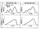
第1実施形態の熱発生率を示すグラフである。
第1実施形態のEGR率と性能との関係を示すグラフである。
第1実施形態の切替制御を示すフローチャートである。
第1実施形態の水温閾値を示すマップである。
第1実施形態の吸気酸素濃度閾値を示すマップである。
第2実施形態の切替制御を示すフローチャートである。
第2実施形態のインマニ圧閾値を示すマップである。
第2実施形態の吸気酸素濃度閾値を示すマップである。
第3実施形態の切替制御を示すフローチャートである。
第4実施形態の切替制御を示すフローチャートである。
第5実施形態の切替制御を示すフローチャートである。
第5実施形態の燃え易さ判定水温閾値を示すマップである。
第6実施形態の切替制御を示すフローチャートである。
第7実施形態の切替制御を示すフローチャートである。
第7実施形態の燃え易さを示すマップである。
第8実施形態の切替制御を示すフローチャートである。
以下、図面を参照しながら複数の実施形態を説明する。各実施形態で先行する実施形態で説明している事項に対応している部分には同一の参照符を付すか、または先行の参照符号に一文字追加し、重複する説明を略する場合がある。また各実施形態にて構成の一部を説明している場合、構成の他の部分は、先行して説明している実施形態と同様とする。各実施形態で具体的に説明している部分の組合せばかりではなく、特に組合せに支障が生じなければ、実施形態同士を部分的に組合せることも可能である。
(第1実施形態)
第1実施形態に関して、図1~図7を用いて説明する。本実施形態では、燃料噴射制御装置をコモンレール式燃料噴射装置が備えられる多気筒ディーゼルエンジンに適用している。
第1実施形態に関して、図1~図7を用いて説明する。本実施形態では、燃料噴射制御装置をコモンレール式燃料噴射装置が備えられる多気筒ディーゼルエンジンに適用している。
本実施形態において、図1に示すエンジン10は、車載主機として車両に搭載されており、吸気、圧縮、膨張及び排気行程からなる4サイクルエンジンである。内燃機関であるエンジン10の吸気通路11には、上流側から順に、吸入される空気量を検出するエアフローメータ12、ターボチャージャ16によって過給された吸気を冷却するインタークーラ13、およびスロットルバルブ装置14が設けられている。スロットルバルブ装置14は、DCモータ等のアクチュエータにより、スロットルバルブ14aの開度を調節する。
吸気通路11においてスロットルバルブ装置14の下流側には、サージタンク15を介してエンジン10の各気筒の燃焼室10aが接続されている。燃焼室10aは、エンジン10のシリンダ10bおよびピストン17にて区画されている。エンジン10には、燃焼室10a内に先端部が突出した燃料噴射弁18が設けられている。燃料噴射弁18には、蓄圧容器としてのコモンレール19から高圧の燃料、具体的には軽油が供給される。コモンレール19には、燃料ポンプ20から燃料が圧送される。なお、図1では、1つの気筒のみを示している。
燃料噴射弁18は、ニードルと、燃料を噴射する円形の噴孔が先端部に複数形成され、内部にニードルが収容されるボディとを備えている。ボディの内面とニードルの外面との間には、ボディの軸方向に延びてかつコモンレール19から供給された燃料が通過する環状の燃料通路が形成されている。ボディ先端部の内面には、ニードルの先端部が着座する着座面が形成されている。この構成において、ニードルを着座面に着座させることにより、燃料通路と噴孔との間が遮断され、燃料噴射が停止される。一方、通電操作によってニードルを着座面から離座させることにより、燃料通路と噴孔との間が連通される。その結果、燃料通路の燃料は、噴孔から燃焼室10aへと直接噴射供給される。
燃料噴射弁18は、噴射率波形を可変に制御できる構成とされている。噴射率波形とは、噴射率の時間経過における変化を示した波形である。本実施形態において、燃料噴射弁18は、噴射率波形を可変に制御すべく、ニードルのリフト量を自在に制御できる構成とされている。たとえば燃料噴射弁18は、ピエゾ素子を有するアクチュエータにより、燃料流路の面積を調節して燃料の噴射を行う。これによって燃料噴射弁は、燃料の噴射率波形を変更可能であり、例えばメイン噴射における噴射率を時間経過につれて異ならせることができる。
燃料噴射弁18のアクチュエータは、たとえばピエゾスタックを含んで構成される。ピエゾスタックは、たとえばPZT(PbZrTiO3)と呼ばれる層と薄い電極層が交互に積まれた積層体で、ピエゾ素子の特性である逆圧電効果により電圧を印加することで伸び縮みする。アクチュエータは、ピエゾスタックの変位を用いて、ニードルの位置を制御する。
たとえばピエゾスタックに電圧が印加されていない状態では、ニードルは閉じた状態であり、燃料噴射は行われない。そしてピエゾスタックに電圧を印加すると、ピエゾスタックは膨張して、膨張を動力として、ニードルが押し上げられ燃料噴射が開始される。ピエゾスタックに印加されている電圧をオフにすると、放電して、ピエゾスタックは収縮する。これによってニードルが押し下げられ燃料噴射が停止する。アクチュエータに供給する電圧を制御することによって、ピエゾスタックの膨張量を制御することができる。したがって電圧を制御することによって、ニードルの開弁速度を複数の段階にわたって調整することができるので、噴射シールを自在に制御できる。
エンジン10の各気筒の吸気ポートおよび排気ポートのそれぞれは、吸気バルブ21および排気バルブ22のそれぞれにより開閉される。ここでは、吸気バルブ21の開弁によってインタークーラ13で冷却された吸気、および外部EGRガスが燃焼室10aに導入される。吸気等が導入された状態で燃料噴射弁18から燃焼室10aに燃料が噴射されると、燃焼室10aの圧縮によって燃料が自己着火し、燃焼によってエネルギが発生する。このエネルギは、ピストン17を介して、エンジン10のクランク軸23の回転エネルギとして取り出される。燃焼に供されたガスは、排気バルブ22の開弁によって、排気通路24に排気として排出される。なお、クランク軸23付近には、クランク軸23の回転角度を検出するクランク角度センサ25が設けられている。
車両には、ターボチャージャ16が設けられている。ターボチャージャ16は、吸気通路11に設けられた吸気コンプレッサ16aと、排気通路24に設けられた排気タービン16bと、これらを連結する回転軸16cとを備えている。詳しくは、排気通路24を流れる排気のエネルギによって排気タービン16bが回転し、その回転エネルギが回転軸16cを介して吸気コンプレッサ16aに伝達され、吸気コンプレッサ16aによって吸気が圧縮される。すなわち、ターボチャージャ16によって吸気が過給される。なお本実施形態では、ターボチャージャ16として、通電操作によって吸気の過給圧を調節可能なものを想定している。
排気通路24のうちターボチャージャ16の下流側には、排気を浄化する浄化装置26が設けられている。また排気通路24に排出された排気の一部は、EGR通路27を介して吸気通路11に還流される。詳しくは、排気通路24のうち排気タービン16bの上流側は、EGR通路27を介してサージタンク15に接続されている。EGR通路27には、EGRバルブ装置28が設けられている。EGRバルブ装置28は、DCモータ等のアクチュエータにより、EGRバルブ28aの開度を調節する。EGRバルブ28aの開度に応じて、排気通路24に排出された排気の一部が、EGRクーラ29によって冷却された後に外部EGRガスとしてサージタンク15に供給される。
エンジンシステムを制御対象とする電子制御装置であるECU30は、記憶媒体に記憶されているプログラムを実行し、各部を制御する。ECUは、少なくともひとつの演算処理装置(CPU)と、プログラムとデータとを記憶する記憶媒体とを有する。ECUは、たとえばコンピュータによって読み取り可能な記憶媒体を備えるマイクロコンピュータ(以下、「マイコン」ということがある)によって実現される。記憶媒体は、コンピュータによって読み取り可能なプログラムおよびデータを非一時的に格納する非遷移的実体的記憶媒体である。メモリは、半導体メモリまたは磁気ディスクなどによって実現される。
ECU30には、吸気圧センサ31、吸気温センサ32、排気温センサ33、筒内圧センサ34、酸素濃度センサ38、燃圧センサ35、水温センサ36、アクセルセンサ37、エアフローメータ12、およびクランク角度センサ25の検出値が入力される。吸気圧センサ31は、サージタンク15内のガス圧力を検出する。吸気温センサ32は、サージタンク15内のガス温度を検出する。排気温センサ33は、燃焼室10aから排出された排気の温度を検出する。筒内圧センサ34は、燃焼室10a内の圧力である筒内圧を検出する。酸素濃度センサ38は、吸気通路11に取り付けられ、吸気中の酸素濃度を検出する。検出対象となる吸気は、新気とEGRガスが混合したものである。燃圧センサ35は、コモンレール19内の燃料圧力を検出する。水温センサ36は、エンジン10の冷却水温を検出する。クランク角度センサ25は、ピストン17により回転駆動するクランク軸23の回転速度であって、単位時間あたりのクランク軸23の回転数であるエンジン回転数を検出する。アクセルセンサ37は、ドライバのアクセル操作部材のアクセル操作量を検出し、具体的にはアクセルペダルの踏み込み量を検出する。
ECU30は、各種センサの検出値に基づいて、燃料噴射弁18の燃料噴射制御、燃料ポンプ20の駆動制御、EGRバルブ装置28の駆動制御、およびターボチャージャ16による過給圧制御を含むエンジン10の燃焼制御を行う。これらの制御により、燃焼システムが備えるエンジン10での燃焼状態は、所望の状態に制御される。したがってECU30は、噴射率を制御する制御部として機能する。
次に、噴射モードに関して説明する。本実施形態では、2つの噴射モードである第1噴射モードと、第2噴射モードとを有し、所定のタイミングで切替制御を行っている。図2では、第1噴射モードを実線で示し、第2噴射モードを破線で示す。
第1噴射モードは、噴射を多段化し、経過時間に対して各段の噴射率のピークが徐々に上昇する多段噴射率波形を有する。換言すると、第1噴射モードは、噴射を多段化し、各段の噴射を予め決めた量、および時期にて噴射する噴射率波形を有する。図2に示す第1噴射モードは、噴射を3段化し、最初の2段は三角形状であり、最終段は台形状である。各段のピークは、初段が最も小さく、徐々に大きくなっている。
第2噴射モードは、噴射を間欠することなく、経過時間に対して徐々に噴射率が上昇する上昇噴射率波形を有する。第2噴射モードは、いわゆるブーツ型といわれる形状であり、最初の噴射率の傾きが大きい状態から、傾きが小さい状態となり、最大噴射率に達するまで噴射率が小さくなることがない波形である。
次に、筒内の燃え易さの違いと、噴射率および熱発生率との関係について、図3を用いて説明する。図3に示すように、燃え難い筒内においては、噴射率モードによらず、緩やかに上昇する波形となる。一方、燃え易い筒内においては、着火しやすいので着火遅れが短く、熱発生率は噴射率形状と似た波形になる。具体的には、燃え易い状態では、第1噴射モードでは、熱発生率は、噴射率波形に似たうねりを持つ波形となる。
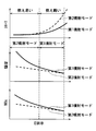
次に、燃え易さの違いと、スモーク、騒音およびNOxとの関係について、図4を用いて説明する。グラフの右側の燃え難い状態では、第1噴射モードでも、熱発生率を緩やかに上昇させることができるので、燃焼騒音およびNOxを抑制可能である。また燃え難い状態では、第1噴射モードは、第2噴射モードに比べ、開弁速度が速いので、強制的なシートチョークが少ない噴射が可能であるので、空気と混合しやすい噴霧を形成できる。これによって第1噴射モードは、スモークも抑制可能である。換言すると、開弁速度が速い第1噴射モードでは、シートチョークが発生する時間が第2噴射モードよりも短いので、スモークを抑制できる。シートチョークは、シート絞りとも呼ばれ、ニードルが弁座から離座するときに形成されるニードルと弁座との隙間のことである。
これに対して、燃え易い状態では、第2噴射モードで噴射することによって、熱発生率を緩やかに上昇させ、燃焼騒音およびNOxを抑制できることがわかる。また、本制御を暖機中等や高負荷での低EGR時において適用するので、スモークは少ない。
したがってEGR率が低い場合には、第2噴射モードで噴射し、EGR率が高い場合には、第1噴射モードで噴射することが好ましい。換言すると、暖機中のEGR、高負荷のEGR、および過給圧を指標に、噴射モードを切替え、運転状態に応じた低騒音および低エミッションが可能となる。
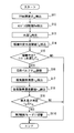
次に、噴射モードと切替制御に関して、図5~図7を用いて説明する。図5に示す切替制御は、第1噴射モードで噴射を制御しているときに、繰り返し実施される制御である。ステップS11では、アクセル開度θacを検出し、ステップS12に移る。ECU30は、アクセルセンサ37からアクセル開度θacを取得する。
ステップS12では、エンジン回転数Neを検出し、ステップS13に移る。ECU30は、クランク角度センサ25からエンジン回転数Neを取得する。ステップS13では、水温Twを検出し、ステップS14に移る。ECU30は、水温センサ36から水温Twを取得する。
ステップS14では、暖機判定水温閾値Tthを読込み、ステップS15に移る。暖機判定水温閾値Tthは、記憶媒体に予め記憶されている値である。暖機判定水温閾値Tthは予め決めた一定値、または検出したアクセル開度θacおよびエンジン回転数Neに基づく数値である。後者の場合は、たとえば図6のマップを用いて暖機判定水温閾値Tthが決定される。
ステップS15では、暖機中であるか否かを判定し、暖機中の場合は、ステップS16に移り、暖機中でない場合には、本フローが終了する。暖機中である否かは、暖機判定水温閾値Tthと水温Twとを比較し、水温Twが暖機判定水温閾値Tthよりも小さい場合に暖機中であると判断される。換言すると、水温Twが所定の暖機判定水温閾値Tthよりも小さい場合は、まだ水温が低いので暖機中である。
ステップS16では、水温Twに基づき、EGR量の調整し、ステップS17に移る。具体的に、水温Twが冷たいほど、筒内は冷めやすく、燃え難い状況にあるので、EGR量を減らすべく、EGRバルブ開度θEGRを調整する。
ステップS17では、吸気酸素濃度rO2を検出し、ステップS18に移る。ECU30は、酸素濃度センサ38から吸気酸素濃度rO2を取得する。したがってECU30は、吸気の酸素濃度を取得する酸素濃度取得部として機能する。
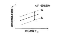
ステップS18では、吸気酸素濃度閾値rthを読込み、ステップS19に移る。吸気酸素濃度閾値rthは、記憶媒体に予め記憶されている値である。吸気酸素濃度閾値rthは予め決めた一定値、または検出したアクセル開度θacおよびエンジン回転数Neに基づく数値である。後者の場合は、たとえば図7のマップを用いて吸気酸素濃度閾値rthが決定される。
ステップS19では、燃え易いか否かを判定し、燃え易い場合は、ステップS110に移り、燃え難い場合には、本フローが終了する。燃え易いか否かは、吸気酸素濃度rO2と吸気酸素濃度閾値rthとを比較し、吸気酸素濃度rO2が吸気酸素濃度閾値rth以上である場合に、酸素が多くあるので燃え易いと判断される。ステップS110では、噴射モードを第2噴射モードに切替え、本フローを終了する。
このように暖機中であり、燃え易い場合には、噴射モードが第1噴射モードから第2噴射モードへと切替へられる。前述のように第2噴射モードは、燃え易い場合に、NOxの発生を抑制でき、騒音を抑制することができる。
以上説明したように本実施形態では、酸素濃度が所定の酸素濃度以上である場合には、筒内が燃えやすい状態にあるので、噴射率の変化率を大きくすると、騒音が大きくなる。そこで本実施形態は、燃えやすい状態の場合は、噴射を間欠することなく、経過時間に対して徐々に噴射率が上昇する上昇噴射率波形である第2噴射モードで噴射するように制御される。これによって燃え易い状態でも熱発生率が徐々に上昇するので、NOxを抑制しつつ、燃焼騒音を小さくすることができる。また酸素濃度が所定の酸素濃度よりも小さい場合は、他の噴射モードである第1噴射モードに制御することによって、酸素濃度が低く燃えがたい場合も、前述のようにNOx、騒音およびスモークを抑制することができる。
また本実施形態では、暖機中の場合に気筒内の燃え易さを判定し、暖機中でありかつ燃え易い場合には第2噴射モードに切り替えている。暖機中であれば、通常、暖機を完了するために第1噴射モードの実施を優先するが、燃え易い場合には第1噴射モードによる燃焼騒音が大きくなるデメリットを補うために第2噴射モードを実施する。これによって暖機中の燃え易い場合に、燃焼騒音を抑制することができる。
さらに本実施形態では、燃え易さの指標として酸素濃度を用いており、指標取得部によって取得された指標と所定の閾値とを比較した結果、燃え易いと判断される場合には第2噴射モードに切り替えている。燃え易さの指標として酸素濃度を用いることによって、燃え易さを精度よく判断して、第2噴射モードに切り替えることができる。
(第2実施形態)
次に、第2実施形態に関して、図8~図10を用いて説明する。本実施形態では、酸素濃度だけでなく、過給量も考慮して噴射モードを切り替える点に特徴を有する。図8に示す切替制御は、第1噴射モードで噴射を制御しているときに、繰り返し実施される制御である。ステップS21では、ステップS11と同様に、アクセル開度θacを検出し、ステップS22に移る。
次に、第2実施形態に関して、図8~図10を用いて説明する。本実施形態では、酸素濃度だけでなく、過給量も考慮して噴射モードを切り替える点に特徴を有する。図8に示す切替制御は、第1噴射モードで噴射を制御しているときに、繰り返し実施される制御である。ステップS21では、ステップS11と同様に、アクセル開度θacを検出し、ステップS22に移る。
ステップS22では、ステップS12と同様に、エンジン回転数Neを検出し、ステップS23に移る。ステップS23では、インマニ圧Pimを検出し、ステップS24に移る。ECU30は、筒内圧センサ34から筒内圧であるインマニ圧Pimを取得する。インマニ圧Pimは、過給量と相関関係にある。本制御では、過給量に換えてインマニ圧Pimを用いる。したがってECU30は、過給量を取得する過給量取得部として機能する。
ステップS24では、ステップS16と同様に、吸気酸素濃度rO2を検出し、ステップS25に移る。ステップS25では、インマニ圧閾値Pthを読込み、ステップS26に移る。インマニ圧閾値Pthは、予め決めた一定値、または検出したアクセル開度θac、エンジン回転数Neおよびインマニ圧閾値Pthに基づく数値である。後者の場合は、たとえば図9の吸気酸素毎のマップ、すなわち三次元マップを用いてインマニ圧閾値Pthが決定される。図9では、2つの吸気濃度について一例として示しているが、記憶媒体には複数の吸気濃度についてインマニ圧閾値Pthとアクセル開度θacの関係が記憶されている。
ステップS26では、吸気酸素濃度閾値rthを読込み、ステップS27に移る。吸気酸素濃度閾値rthは、予め決めた一定値、または検出したアクセル開度θac、エンジン回転数Neおよびインマニ圧閾値Pthに基づく数値である。後者の場合は、たとえば図10のインマニ圧毎のマップ、すなわち三次元マップを用いて吸気酸素濃度閾値rthが決定される。図10では、2つのインマニ圧について一例として示しているが、記憶媒体には複数のインマニ圧について吸気酸素濃度閾値rthとアクセル開度θacの関係が記憶されている。
ステップS27では、燃え易いか否かを判定し、燃え易い場合は、ステップS28に移り、燃え難い場合には、本フローが終了する。燃え易いか否かは、吸気酸素濃度rO2と吸気酸素濃度閾値rthとを比較し、吸気酸素濃度rO2が吸気酸素濃度閾値rth以上であり、かつインマニ圧Pimとインマニ圧閾値Pthとを比較し、インマニ圧Pimがインマニ圧閾値Pth以上である場合に、燃え易いと判断される。ステップS29では、噴射モードを第2噴射モードに切替え、本フローを終了する。
このように吸気酸素濃度rO2およびインマニ圧Pimから燃え易いと判断された場合には、噴射モードが第1噴射モードから第2噴射モードへと切替へられる。またインマニ圧Pimである過給圧が高い場合は、高負荷の場合であり、このような燃え易く高負荷の場合に第2噴射モードに切替られる。図10に示すように、インマニ圧Pimと吸気酸素濃度閾値rthとに相関関係があり、インマニ圧Pimが高くなると吸気酸素濃度閾値rthが小さくなる。このように吸気酸素濃度rO2およびインマニ圧Pimから燃え易いか否かを判断するので、燃え易いか否かの判断精度を向上することができる。
したがって前述のように第2噴射モードは、燃え易い場合に、NOxの発生を抑制でき、騒音を抑制することができる。したがって前述の第1実施形態と同様に、適切なタイミングで第2噴射モードに切り替えることによって、排ガスを改善しつつ、燃焼騒音を小さくすることができる。
(第3実施形態)
次に、第3実施形態に関して、図11を用いて説明する。本実施形態では、第2噴射モードから第1噴射モードに切替える点に特徴を有する。換言すると、本実施形態では、通常は第2噴射モードが実施され、図11に示す切替制御によって第2噴射モードから第1噴射モードへ切り替える。
次に、第3実施形態に関して、図11を用いて説明する。本実施形態では、第2噴射モードから第1噴射モードに切替える点に特徴を有する。換言すると、本実施形態では、通常は第2噴射モードが実施され、図11に示す切替制御によって第2噴射モードから第1噴射モードへ切り替える。
図11に示す切替制御は、第2噴射モードで噴射を制御しているときに、繰り返し実施される制御である。本実施形態の切替制御は、前述の第1実施形態の図5の切替制御と類似しており、ステップS35、ステップS38およびステップS39が異なり、他のステップS31~ステップS34、ステップS36、ステップS37は同じ処理である。
ステップS31では、アクセル開度θacを検出し、ステップS32に移る。ステップS32では、エンジン回転数Neを検出し、ステップS33に移る。ステップS33では、水温Twを検出し、ステップS34に移る。ステップS34では、暖機判定水温閾値Tthを読込み、ステップS35に移る。ステップS35では、暖機中であるか否かを判定し、暖機中でない場合は、ステップS36に移り、暖機中の場合には、本フローが終了する。
ステップS36では、水温Twに基づき、EGR量を調整し、ステップS37に移る。具体的に、水温Twが冷たいほど、筒内は冷めやすく、燃え難い状況にあるので、EGR量を減らすべく、EGRバルブ開度θEGRを調整する。
ステップS37では、吸気酸素濃度rO2を検出し、ステップS38に移る。ステップS38では、吸気酸素濃度閾値rthを読込み、ステップS39に移る。ステップS39では、燃え易いか否かを判定し、燃え難い場合は、ステップS310に移り、燃え易い場合には、本フローが終了する。燃え易いか否かは、吸気酸素濃度rO2と吸気酸素濃度閾値rthとを比較し、吸気酸素濃度rO2が吸気酸素濃度閾値rth以下である場合に、酸素が少ないので燃え難いと判断される。ステップS310では、噴射モードを第1噴射モードに切替え、本フローを終了する。
したがって本実施形態では、酸素濃度が所定の酸素濃度以下である場合には、噴射を多段化し、経過時間に対して各段の噴射率のピークが徐々に上昇する噴射率波形である第1噴射モードで噴射するように制御する。具体的には、暖機中でなく、燃え難い場合には、噴射モードが第2噴射モードから第1噴射モードへと切替へられる。前述のように第1噴射モードは、燃え難い場合に、スモークの発生を抑制でき、さらにNOxの発生および騒音も抑制することができる。したがって第2噴射モードを継続した場合のデメリットを第1噴射モードに切り替えることによって補うことができる。
(第4実施形態)
次に、第4実施形態に関して、図12を用いて説明する。本実施形態では、第3実施形態と同様に、第2噴射モードから第1噴射モードに切替える点に特徴を有する。換言すると、本実施形態では、通常は第2噴射モードが実施され、図12に示す切替制御によって第2噴射モードから第1噴射モードへ切り替える。
次に、第4実施形態に関して、図12を用いて説明する。本実施形態では、第3実施形態と同様に、第2噴射モードから第1噴射モードに切替える点に特徴を有する。換言すると、本実施形態では、通常は第2噴射モードが実施され、図12に示す切替制御によって第2噴射モードから第1噴射モードへ切り替える。
図12に示す切替制御は、第2噴射モードで噴射を制御しているときに、繰り返し実施される制御である。本実施形態の切替制御は、前述の第2実施形態の図8の切替制御と類似しており、ステップS47およびステップS48が異なり、他のステップS41~ステップS46は同じ処理である。
ステップS41では、アクセル開度θacを検出し、ステップS42に移る。ステップS42では、エンジン回転数Neを検出し、ステップS43に移る。ステップS43では、インマニ圧Pimを検出し、ステップS44に移る。
ステップS44では、吸気酸素濃度rO2を検出し、ステップS45に移る。ステップS45では、インマニ圧閾値Pthを読込み、ステップS46に移る。ステップS46では、吸気酸素濃度閾値rthを読込み、ステップS47に移る。
ステップS47では、燃え難いか否かを判定し、燃え難い場合は、ステップS48に移り、燃え易い場合には、本フローが終了する。燃え難いか否かは、吸気酸素濃度rO2と吸気酸素濃度閾値rthとを比較し、吸気酸素濃度rO2が吸気酸素濃度閾値rth以下であり、かつインマニ圧Pimとインマニ圧閾値Pthとを比較し、インマニ圧Pimがインマニ圧閾値Pth以下である場合に、燃え難いと判断される。ステップS49では、噴射モードを第1噴射モードに切替え、本フローを終了する。
したがって本実施形態では、酸素濃度が所定の酸素濃度以下であり、かつ過給量が所定の過給量以下である場合には、第1噴射モードで噴射するように制御する。吸気酸素濃度rO2およびインマニ圧Pimから燃え難いと判断された場合には、噴射モードが第2噴射モードから第1噴射モードへと切替へられる。前述のように第1噴射モードは、燃え難い場合に、スモークの発生を抑制でき、さらにNOxの発生および騒音も抑制することができる。したがって第2噴射モードを継続した場合のデメリットを第1噴射モードに切り替えることによって補うことができる。
(第5実施形態)
次に、第5実施形態に関して、図13および図14を用いて説明する。本実施形態では、第1噴射モードから第2噴射モードに切替える点に特徴を有する。換言すると、本実施形態では、通常は第1噴射モードが実施され、図13に示す切替制御によって第1噴射モードから第2噴射モードへ切り替える。
次に、第5実施形態に関して、図13および図14を用いて説明する。本実施形態では、第1噴射モードから第2噴射モードに切替える点に特徴を有する。換言すると、本実施形態では、通常は第1噴射モードが実施され、図13に示す切替制御によって第1噴射モードから第2噴射モードへ切り替える。
図13に示す切替制御は、第1噴射モードで噴射を制御しているときに、繰り返し実施される制御である。本実施形態の切替制御は、前述の第1実施形態の図5の切替制御と類似しており、ステップS54、ステップS55が異なり、他のステップS51~ステップS53、ステップS56は同じ処理である。
ステップS51では、アクセル開度θacを検出し、ステップS52に移る。ステップS52では、エンジン回転数Neを検出し、ステップS53に移る。ステップS53では、水温Twを検出し、ステップS54に移る。したがってECU30は、エンジンの冷却水温を取得する水温取得部として機能する。
ステップS54では、燃え易さ判定水温閾値Tth0を読込み、ステップS55に移る。燃え易さ判定水温閾値Tth0は、記憶媒体に予め記憶されている値である。燃え易さ判定水温閾値Tth0は予め決めた一定値、または検出したアクセル開度θacおよびエンジン回転数Neに基づく数値である。後者の場合は、たとえば図14のマップを用いて燃え易さ判定水温閾値Tth0が決定される。
ステップS55では、燃え易いか否かを判定し、燃え易い場合は、ステップS56に移り、燃え難い場合は、本フローを終了する。燃え易いか否かは、水温Twと燃え易さ判定水温閾値Tth0とを比較し、水温Twが燃え易さ判定水温閾値Tth0よりも大きい場合に、燃え易いと判断される。ステップS56では、噴射モードを第2噴射モードに切替え、本フローを終了する。
このように本実施形態では、筒内の燃え易さを判定する指標として、酸素濃度ではなく、エンジン水温を指標としている。エンジン水温が所定の水温以上の場合には、筒内は暖かく、燃え易い状態となる。したがって前述の第1実施形態と同様に、適切なタイミングで第2噴射モードに切り替えることによって、排ガスを改善しつつ、燃焼騒音を小さくすることができる。
(第6実施形態)
次に、第6実施形態に関して、図15を用いて説明する。本実施形態では、第2噴射モードから第1噴射モードに切替える点に特徴を有する。換言すると、本実施形態では、通常は第2噴射モードが実施され、図15に示す切替制御によって第2噴射モードから第1噴射モードへ切り替える。
次に、第6実施形態に関して、図15を用いて説明する。本実施形態では、第2噴射モードから第1噴射モードに切替える点に特徴を有する。換言すると、本実施形態では、通常は第2噴射モードが実施され、図15に示す切替制御によって第2噴射モードから第1噴射モードへ切り替える。
図15に示す切替制御は、第2噴射モードで噴射を制御しているときに、繰り返し実施される制御である。本実施形態の切替制御は、前述の第5実施形態の図13の切替制御と類似しており、ステップS65およびステップS66が異なり、他のステップS61~ステップS64は同じ処理である。
ステップS61では、アクセル開度θacを検出し、ステップS62に移る。ステップS62では、エンジン回転数Neを検出し、ステップS63に移る。ステップS63では、水温Twを検出し、ステップS64に移る。ステップS64では、燃え易さ判定水温閾値Tth0を読込み、ステップS65に移る。
ステップS65では、燃え易いか否かを判定し、燃え難い場合は、ステップS66に移り、燃え易い場合は、本フローを終了する。燃え易いか否かは、水温Twと燃え易さ判定水温閾値Tth0とを比較し、水温Twが燃え易さ判定水温閾値Tth0よりも大きい場合に、燃え難いと判断される。ステップS66では、噴射モードを第1噴射モードに切替え、本フローを終了する。
このように本実施形態では、筒内の燃え易さを判定する指標として、酸素濃度ではなく、エンジン水温を指標としてる。エンジン水温が所定の水温以下の場合には、筒内は冷めやすく、燃え難い状態となる。この場合には噴射を多段化するので、熱発生率の上昇がゆるやかなので、NOxを抑制しつつ、燃焼騒音を小さくすることができる。さらに多段化によって噴射率の変化率が大きくなるので、シート絞りが発生する時間が短くなり、スモークの発生を抑制することができる。
このように本実施形態でも、前述の第5実施形態と同様に、筒内の燃え易さを判定する指標として、酸素濃度ではなく、エンジン水温を指標としている。エンジン水温が所定の水温以下の場合には、筒内は冷えており、燃え難い状態となる。この場合には噴射を多段化しても熱発生率の上昇がゆるやかなので、NOxを抑制しつつ、燃焼騒音を小さくすることができる。さらに多段化によって噴射率の変化率が大きくなるので、シート絞りが発生する時間が短くなり、スモークの発生を抑制することができる。したがって前述の第3実施形態と同様に、第2噴射モードを継続した場合のデメリットを第1噴射モードに切り替えることによって補うことができる。
(第7実施形態)
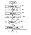
次に、第7実施形態に関して、図16および図17を用いて説明する。本実施形態では、第1噴射モードから第2噴射モードに切替える点に特徴を有する。換言すると、本実施形態では、通常は第1噴射モードが実施され、図16に示す切替制御によって第1噴射モードから第2噴射モードへ切り替える。
次に、第7実施形態に関して、図16および図17を用いて説明する。本実施形態では、第1噴射モードから第2噴射モードに切替える点に特徴を有する。換言すると、本実施形態では、通常は第1噴射モードが実施され、図16に示す切替制御によって第1噴射モードから第2噴射モードへ切り替える。
図16に示す切替制御は、第1噴射モードで噴射を制御しているときに、繰り返し実施される制御である。本実施形態の切替制御は、前述の第5実施形態の図13の切替制御と類似しており、ステップS73が異なり、他のステップS71、ステップS72およびステップS74は同じ処理である。
ステップS71では、アクセル開度θacを検出し、ステップS72に移る。したがってECU30は、アクセル開度θacを取得するアクセル開度取得部として機能する。ステップS72では、エンジン回転数Neを検出し、ステップS73に移る。したがってECU30は、エンジン回転数Neを取得する回転数取得部として機能する。
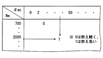
ステップS73では、燃え易いか否かを判定し、燃え易い場合は、ステップS74に移り、燃え難い場合は、本フローを終了する。燃え易いか否かは、図17に示す制御マップを用いて、アクセル開度θacおよびエンジン回転数Neから判断する。具体的には、アクセル開度θacが所定以上で、エンジン回転数が所定以上である場合には、EGRを使わない運転状態となるので、筒内は燃え易い状態となり、図17では「1」が読み出される。図17で読み出される「1」は、燃え易い状態を示し、「0」は燃え難い状態を示す。ステップS74では、噴射モードを第2噴射モードに切替え、本フローを終了する。
このように本実施形態では、筒内の燃え易さを判定する指標として、酸素濃度ではなく、エンジン回転数Neとアクセル開度θacを指標としている。具体的には、エンジン回転数Neが所定の回転数以上であり、かつアクセル開度θacが所定のアクセル開度以上の場合には、第2噴射モードで噴射するように制御されている。エンジン回転数Neが所定の回転数以上であり、かつアクセル開度θacが所定のアクセル開度以上の場合には、燃え易い状態であるので、第2噴射モードに切り替えることによって、排ガスを改善しつつ、燃焼騒音を小さくすることができる。
(第8実施形態)
次に、第8実施形態に関して、図18を用いて説明する。本実施形態では、第2噴射モードから第1噴射モードに切替える点に特徴を有する。換言すると、本実施形態では、通常は第2噴射モードが実施され、図18に示す切替制御によって第2噴射モードから第1噴射モードへ切り替える。
次に、第8実施形態に関して、図18を用いて説明する。本実施形態では、第2噴射モードから第1噴射モードに切替える点に特徴を有する。換言すると、本実施形態では、通常は第2噴射モードが実施され、図18に示す切替制御によって第2噴射モードから第1噴射モードへ切り替える。
図18に示す切替制御は、第2噴射モードで噴射を制御しているときに、繰り返し実施される制御である。本実施形態の切替制御は、前述の第6実施形態の図15の切替制御と類似しており、ステップS83が異なり、他のステップS81、ステップS82およびステップS84は同じ処理である。
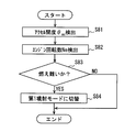
ステップS81では、アクセル開度θacを検出し、ステップS82に移る。ステップS82では、エンジン回転数Neを検出し、ステップS83に移る。
ステップS83では、燃え難いか否かを判定し、燃え難い場合は、ステップS84に移り、燃え易い場合は、本フローを終了する。燃え難いか否かは、図17に示す制御マップを用いて、アクセル開度θacおよびエンジン回転数Neから判断する。ステップS84では、噴射モードを第1噴射モードに切替え、本フローを終了する。
このように本実施形態では、前述の第7実施形態と同様に、筒内の燃え易さを判定する指標として、酸素濃度ではなく、エンジン回転数Neとアクセル開度θacを指標としている。具体的には、エンジン回転数Neが所定の回転数以下であり、かつアクセル開度θacが所定のアクセル開度以下の場合には、第1噴射モードで噴射するように制御されている。エンジン回転数Neが所定の回転数以下であり、かつアクセル開度θacが所定のアクセル開度以下の場合には、燃え難い状態である。したがって第1噴射モードに切り替えることによって、第2噴射モードを継続した場合のデメリットを第1噴射モードに切り替えることによって補うことができる。
以上、実施形態について説明したが、本開示は前述した実施形態に何ら制限されることなく、本開示の主旨を逸脱しない範囲において種々変形して実施することが可能である。
前述の実施形態の構造は、あくまで例示であって、本開示の範囲はこれらの記載の範囲に限定されるものではない。本開示の範囲は、特許請求の範囲の記載によって示され、さらに特許請求の範囲の記載と均等の意味及び範囲内での全ての変更を含むものである。前述の実施形態の変形例について述べる。
前述の第1実施形態では、2つの噴射率波形を切り替えているが、2つの噴射率波形に限るものではなく、3つ以上の噴射率波形を切り替えてもよい。また第1モードと第2モードとを切り替える制御に限るものではなく、第1モードと他の噴射モードとを切り替える制御でもよく、第2モードと他の噴射モードとを切り替える制御でもよい。他の噴射モードは、たとえば噴射率波形が台形状および階段状などがある。
前述の第1実施形態では、第2噴射モードは、ブーツ型の波形であるが、ブーツ型に限るものではなく、徐々に噴射率が上昇する波形であれば、デルタ型であってもよい。
前述の第1実施形態では、吸気の酸素濃度は、酸素濃度センサ38によって取得しているが、酸素濃度センサ38に限るものではなく、酸素濃度を相関のある数値、たとえばEGR率から酸素濃度を推定してもよい。また酸素濃度を推定せず、EGR率を燃え易さの指標としてもよい。したがって、たとえば筒内の燃え易さに関する指標として、EGRバルブ28aの開度、吸入空気量および吸気圧の少なくともいずれか1つを用いてもよい。このような場合には、ECU30は、気筒内の燃え易さの指標を取得する指標取得部として機能し、さらにEGR率を取得するEGR率取得部としても機能する。
前述の第1実施形態では、過給量と相関関係のあるインマニ圧Pimを用いているが、インマニ圧Pimから過給量を推定して、過給量で高負荷か否かを判断してもよい。
前述の第1実施形態では、燃料噴射弁18のアクチュエータは、ピエゾ素子が用いられているが、このような構成に限るものではない。開弁速度を調整可能な構成であればよい。たとえば複数の圧力が異なる圧力室を備え、これらを切り替えて開弁速度を調整する構成であってもよい。
前述の第1実施形態において、ECU30によって実現されていた機能は、前述のものとは異なるハードウェアおよびソフトウェア、またはこれらの組み合わせによって実現してもよい。ECU30は、たとえば噴射制御する制御部など各機能ブロックをそれぞれ1つのプロセッサによって実現してもよい。ECU30は、たとえば他の制御装置と通信し、他の制御装置が処理の一部または全部を実行してもよい。ECU30が電子回路によって実現される場合、それは多数の論理回路を含むデジタル回路、またはアナログ回路によって実現することができる。
本開示は、実施例に準拠して記述されたが、本開示は当該実施例や構造に限定されるものではないと理解される。本開示は、様々な変形例や均等範囲内の変形をも包含する。加えて、様々な組み合わせや形態、さらには、それらに一要素のみ、それ以上、あるいはそれ以下、を含む他の組み合わせや形態をも、本開示の範疇や思想範囲に入るものである。
Claims (15)
- 噴射率波形が可変に構成される燃料噴射弁(18)から、内燃機関(10)の燃焼室(10a)内への燃料の噴射を制御する燃料噴射制御装置であって、
気筒内の燃え易さに関する指標を取得する指標取得部(30)と、
複数の前記噴射率波形を用いて燃料噴射を制御する制御部(30)と、を備え、
前記制御部は、前記指標取得部によって取得された指標と所定の閾値とを比較した結果、燃え易いと判断される場合には、複数の前記噴射率波形のうち、噴射を間欠することなく、経過時間に対して徐々に噴射率が上昇する上昇噴射率波形で噴射するように制御する燃料噴射制御装置。 - 前記指標取得部は、吸気の酸素濃度を取得する酸素濃度取得部(30)であり、
前記制御部は、前記酸素濃度取得部によって取得された酸素濃度が所定の酸素濃度以上である場合には、複数の前記噴射率波形のうち上昇噴射率波形で噴射するように制御する請求項1に記載の燃料噴射制御装置。 - 過給量を取得する過給量取得部(30)をさらに備え、
前記制御部は、前記酸素濃度取得部によって取得された酸素濃度が所定の酸素濃度以上であり、かつ前記過給量取得部によって取得された過給量が所定の過給量以上である場合には、前記上昇噴射率波形で噴射するように制御する請求項2に記載の燃料噴射制御装置。 - 噴射率波形が可変に構成される燃料噴射弁(18)から、内燃機関(10)の燃焼室(10a)内への燃料の噴射を制御する燃料噴射制御装置であって、
気筒内の燃え易さに関する指標を取得する指標取得部(30)と、
複数の前記噴射率波形を用いて燃料噴射を制御する制御部(30)と、を備え、
前記制御部は、前記指標取得部によって取得された指標と所定の閾値と比較した結果、燃え難いと判断される場合には、複数の前記噴射率波形のうち、噴射を多段化し、経過時間に対して各段の噴射率のピークが徐々に上昇する多段噴射率波形で噴射するように制御する燃料噴射制御装置。 - 前記指標取得部は、吸気の酸素濃度を取得する酸素濃度取得部(30)であり、
前記制御部は、前記酸素濃度取得部によって取得された酸素濃度が所定の酸素濃度以下である場合には、複数の前記噴射率波形のうち前記多段噴射率波形で噴射するように制御する請求項4に記載の燃料噴射制御装置。 - 過給量を取得する過給量取得部(30)をさらに備え、
前記制御部は、前記酸素濃度取得部によって取得された酸素濃度が所定の酸素濃度以下であり、かつ前記過給量取得部によって取得された過給量が所定の過給量以下である場合には、前記多段噴射率波形で噴射するように制御する請求項5に記載の燃料噴射制御装置。 - 前記制御部は、前記酸素濃度取得部によって取得された酸素濃度が所定の酸素濃度より大きい場合には、噴射を間欠することなく、経過時間に対して徐々に噴射率が上昇する上昇噴射率波形で噴射するように制御する請求項5に記載の燃料噴射制御装置。
- 前記制御部は、前記酸素濃度取得部によって取得された酸素濃度が所定の酸素濃度より大きく、かつ前記過給量取得部によって取得された過給量が所定の過給量より大きい場合には、噴射を間欠することなく、経過時間に対して徐々に噴射率が上昇する上昇噴射率波形で噴射するように制御する請求項6に記載の燃料噴射制御装置。
- 前記指標取得部は、気筒内の燃え易さに関する指標として、EGRバルブ(28a)の開度、吸入空気量および吸気圧の少なくともいずれか1つを用いる請求項1または4に記載の燃料噴射制御装置。
- 前記指標取得部は、EGR率を取得するEGR率取得部(30)であり、
前記制御部は、前記EGR率取得部によって取得されたEGR率が所定のEGR率以下である場合には、複数の前記噴射率波形のうち前記上昇噴射率波形で噴射するように制御する請求項1に記載の燃料噴射制御装置。 - 前記指標取得部は、EGR率を取得するEGR率取得部(30)であり、
前記制御部は、前記EGR率取得部によって取得されたEGR率が所定のEGR率以上である場合には、複数の前記噴射率波形のうち前記多段噴射率波形で噴射するように制御する請求項4に記載の燃料噴射制御装置。 - 前記指標取得部は、前記内燃機関を冷却する冷却水温を取得する水温取得部(30)であり、
前記制御部は、前記水温取得部によって取得された水温が所定の水温以上である場合には、複数の前記噴射率波形のうち前記上昇噴射率波形で噴射するように制御する請求項1に記載の燃料噴射制御装置。 - 前記指標取得部は、前記内燃機関を冷却する冷却水温を取得する水温取得部(30)であり、
前記制御部は、前記水温取得部によって取得された水温が所定の水温以下である場合には、複数の前記噴射率波形のうち前記多段噴射率波形で噴射するように制御する請求項4に記載の燃料噴射制御装置。 - 前記指標取得部は、前記内燃機関の回転数を取得する回転数取得部(30)、およびアクセル開度を取得するアクセル開度取得部(30)であり、
前記制御部は、前記回転数取得部によって取得された回転数が所定の回転数以上であり、かつ前記アクセル開度取得部によって取得されたアクセル開度が所定のアクセル開度以上の場合には、複数の前記噴射率波形のうち前記上昇噴射率波形で噴射するように制御する請求項1に記載の燃料噴射制御装置。 - 前記指標取得部は、前記内燃機関の回転数を取得する回転数取得部(30)、およびアクセル開度を取得するアクセル開度取得部(30)であり、
前記制御部は、前記回転数取得部によって取得された回転数が所定の回転数以下であり、かつ前記アクセル開度取得部によって取得されたアクセル開度が所定のアクセル開度以下である場合には、複数の前記噴射率波形のうち前記多段噴射率波形で噴射するように制御する請求項4に記載の燃料噴射制御装置。
Applications Claiming Priority (2)
| Application Number | Priority Date | Filing Date | Title |
|---|---|---|---|
| JP2015-243349 | 2015-12-14 | ||
| JP2015243349A JP6350505B2 (ja) | 2015-12-14 | 2015-12-14 | 燃料噴射制御装置 |
Publications (1)
| Publication Number | Publication Date |
|---|---|
| WO2017104559A1 true WO2017104559A1 (ja) | 2017-06-22 |
Family
ID=59056596
Family Applications (1)
| Application Number | Title | Priority Date | Filing Date |
|---|---|---|---|
| PCT/JP2016/086689 Ceased WO2017104559A1 (ja) | 2015-12-14 | 2016-12-09 | 燃料噴射制御装置 |
Country Status (2)
| Country | Link |
|---|---|
| JP (1) | JP6350505B2 (ja) |
| WO (1) | WO2017104559A1 (ja) |
Citations (6)
| Publication number | Priority date | Publication date | Assignee | Title |
|---|---|---|---|---|
| JPH1193735A (ja) * | 1997-09-18 | 1999-04-06 | Nissan Motor Co Ltd | ディーゼルエンジンの制御装置 |
| JP2000234551A (ja) * | 1999-02-16 | 2000-08-29 | Mitsubishi Motors Corp | 蓄圧式燃料噴射制御装置 |
| JP2001159379A (ja) * | 1999-09-22 | 2001-06-12 | Mitsubishi Motors Corp | 蓄圧式燃料噴射装置 |
| JP2004108320A (ja) * | 2002-09-20 | 2004-04-08 | Isuzu Motors Ltd | 排気ガス浄化方法及びそのシステム |
| JP2010025072A (ja) * | 2008-07-24 | 2010-02-04 | Denso Corp | 内燃機関の制御装置及び制御システム |
| JP2016130496A (ja) * | 2015-01-14 | 2016-07-21 | トヨタ自動車株式会社 | 内燃機関 |
-
2015
- 2015-12-14 JP JP2015243349A patent/JP6350505B2/ja not_active Expired - Fee Related
-
2016
- 2016-12-09 WO PCT/JP2016/086689 patent/WO2017104559A1/ja not_active Ceased
Patent Citations (6)
| Publication number | Priority date | Publication date | Assignee | Title |
|---|---|---|---|---|
| JPH1193735A (ja) * | 1997-09-18 | 1999-04-06 | Nissan Motor Co Ltd | ディーゼルエンジンの制御装置 |
| JP2000234551A (ja) * | 1999-02-16 | 2000-08-29 | Mitsubishi Motors Corp | 蓄圧式燃料噴射制御装置 |
| JP2001159379A (ja) * | 1999-09-22 | 2001-06-12 | Mitsubishi Motors Corp | 蓄圧式燃料噴射装置 |
| JP2004108320A (ja) * | 2002-09-20 | 2004-04-08 | Isuzu Motors Ltd | 排気ガス浄化方法及びそのシステム |
| JP2010025072A (ja) * | 2008-07-24 | 2010-02-04 | Denso Corp | 内燃機関の制御装置及び制御システム |
| JP2016130496A (ja) * | 2015-01-14 | 2016-07-21 | トヨタ自動車株式会社 | 内燃機関 |
Also Published As
| Publication number | Publication date |
|---|---|
| JP2017110504A (ja) | 2017-06-22 |
| JP6350505B2 (ja) | 2018-07-04 |
Similar Documents
| Publication | Publication Date | Title |
|---|---|---|
| CN101578442B (zh) | 燃料喷射控制装置和燃料喷射控制方法 | |
| US20100037859A1 (en) | Control device for internal combustion engine, control method, program for performing control method | |
| US9903322B2 (en) | Control device and control method for internal combustion engine with supercharger | |
| US8037742B2 (en) | Systems and methods for engine fuel control | |
| JP5151697B2 (ja) | 内燃機関の制御装置 | |
| CN110219730B (zh) | 内燃机 | |
| JP2007177792A (ja) | 圧縮比変更機構を備えた内燃機関および内燃機関の制御方法 | |
| JP5321844B2 (ja) | 内燃機関の燃料噴射制御装置 | |
| JP2008223542A (ja) | 多種燃料内燃機関の燃料制御装置 | |
| CN100462532C (zh) | 用于内燃发动机的阀门特性控制装置 | |
| JP6350505B2 (ja) | 燃料噴射制御装置 | |
| JP5332871B2 (ja) | 火花点火式内燃機関の燃料噴射制御装置 | |
| JP5075041B2 (ja) | 内燃機関の燃料噴射制御装置 | |
| JP4914874B2 (ja) | 内燃機関の制御装置 | |
| JP7496066B2 (ja) | 車両用内燃機関 | |
| JP6252345B2 (ja) | 内燃機関の制御装置 | |
| JP5786468B2 (ja) | 内燃機関の制御装置 | |
| JP2008069667A (ja) | 2サイクルエンジンの始動方法 | |
| JP2006183493A (ja) | 内燃機関の制御装置 | |
| JP5925099B2 (ja) | 内燃機関の制御装置 | |
| JP2018119441A (ja) | エンジンの制御装置 | |
| JP6428592B2 (ja) | 燃料噴射制御装置 | |
| JP4501108B2 (ja) | 内燃機関の燃料噴射制御装置 | |
| US9885293B2 (en) | Control apparatus of engine | |
| KR20250017671A (ko) | 엔진 장치 |
Legal Events
| Date | Code | Title | Description |
|---|---|---|---|
| 121 | Ep: the epo has been informed by wipo that ep was designated in this application |
Ref document number: 16875539 Country of ref document: EP Kind code of ref document: A1 |
|
| NENP | Non-entry into the national phase |
Ref country code: DE |
|
| 122 | Ep: pct application non-entry in european phase |
Ref document number: 16875539 Country of ref document: EP Kind code of ref document: A1 |