WO2017104595A1 - Dispositif d'injection d'air comprimé - Google Patents
Dispositif d'injection d'air comprimé Download PDFInfo
- Publication number
- WO2017104595A1 WO2017104595A1 PCT/JP2016/086852 JP2016086852W WO2017104595A1 WO 2017104595 A1 WO2017104595 A1 WO 2017104595A1 JP 2016086852 W JP2016086852 W JP 2016086852W WO 2017104595 A1 WO2017104595 A1 WO 2017104595A1
- Authority
- WO
- WIPO (PCT)
- Prior art keywords
- air
- filter
- pipe
- compressed air
- cover member
- Prior art date
- Legal status (The legal status is an assumption and is not a legal conclusion. Google has not performed a legal analysis and makes no representation as to the accuracy of the status listed.)
- Ceased
Links
Images


Classifications
-
- B—PERFORMING OPERATIONS; TRANSPORTING
- B01—PHYSICAL OR CHEMICAL PROCESSES OR APPARATUS IN GENERAL
- B01D—SEPARATION
- B01D46/00—Filters or filtering processes specially modified for separating dispersed particles from gases or vapours
- B01D46/02—Particle separators, e.g. dust precipitators, having hollow filters made of flexible material
- B01D46/04—Cleaning filters
Definitions
- the present invention relates to a compressed air injection device that injects compressed air onto a filter of a filter cloth type dust collector.
- filter cloth type dust collectors are used for dust removal in incinerators and general factories, and for collecting powder in powder factories.
- a bottomed cylindrical filter using a woven fabric or a non-woven fabric as a filter medium is installed.
- Patent Document 1 discloses a dust collector including a reverse injection pipe 12 for removing accumulated dust and a nozzle 13 for injecting compressed air (see FIG. 1 of Patent Document 1).
- This dust collector can perform so-called backwashing in which compressed air is jetted in a direction opposite to the direction of filtration by a filter, and dust and powder adhering to the filter are removed.
- the venturi is used for the injected compressed air to attract outside air, and theoretically, the filter can be washed with a small amount of compressed air.
- it is difficult to align the nozzle and the filter, and there is a problem that if it is slightly shifted, the amount of attracting air is greatly reduced and the performance as designed cannot be exhibited.
- Patent Document 4 discloses a cleaning device for a filter dust removing device.
- Patent Document 5 discloses a bag filter type dust collector that filters dust in combustion exhaust gas.
- the forced air flows from the delivery part to the cylinder by the compressed air from the annular injection hole flowing along the inner wall surface of the cylindrical delivery part by the Coanda effect. Is injected into the shape.
- the cylindrical forced air is amplified by attracting external air from above to the inside in the radial direction, and is injected into the filter. Therefore, the compressed air injected from the injection hole is surely amplified through the delivery part, and is sent almost straight and reaches the back of the filter, so that dust and powder adhering to the filter can be removed well. it can.
- Patent Document 2 when the air speed when filtering air with a filter (hereinafter also referred to as “filtered air speed”) or when the filter diameter is large, dust or dust adhering to the filter is used. In some cases, the body was not fully discharged. Further, Patent Document 3 does not describe that dust and powder attached to the filter are improved by the present invention.
- Patent Documents 4 and 5 do not describe a compressed air injection device having the following configurations (1) to (4).
- the air inlet is provided in the lower wall portion of the annular portion.
- the sending section has a first pipe located on the upper side and a second pipe located on the lower side, which are coaxially arranged and connected to each other so as to be separable from each other.
- a stopper is fixed to the outer peripheral surface of the second pipe.
- the second pipe is fixed to the first pipe by screw fastening at a position where the lower end surface of the stopper contacts the upper surface of the cover member.
- Patent Documents 4 and 5 do not describe a compressed air injection device having the following configurations (1), (2), (5), and (6).
- the air inflow port is provided in the lower wall portion of the annular portion.
- the sending section has a first pipe located on the upper side and a second pipe located on the lower side, which are coaxially arranged and connected to each other so as to be separable from each other.
- the cover member is fixed to the outer peripheral surface of the second pipe.
- the cover member is fixed to the upper opening edge of the filter.
- the present invention has been made in view of such circumstances, and it is an object of the present invention to provide a compressed air injection device capable of more reliably removing dust and powder adhering to a filter of a filter cloth type dust collector. To do.
- the present invention is a compressed air injection device for injecting compressed air to a filter of a filter cloth type dust collector, wherein an air distribution pipe through which compressed air flows and air sent from the air distribution pipe
- An air amplifying device that amplifies the air by attracting outside air and injects it to the filter, and the air circulation pipe has an air outlet through which air to be sent to the air amplifying device passes, and the air amplifying device
- the apparatus includes an air inlet connected to the air outlet, and an annular portion in which an annular injection hole for injecting air introduced through the air inlet is provided, and an annular space is formed therein, A tubular delivery part that is connected to the annular part and delivers the air injected from the injection hole to the filter together with the attracted air, and the air inlet is located below the annular part.
- the tip of the delivery part extends inside the filter, and a cover member that covers the upper end opening of the filter is installed on the radially outer side of the delivery part.
- the second pipe is fixed to the first pipe by screw fastening at a position where the lower end surface of the stopper contacts the upper surface of the cover member.
- the compressed air ejected from the ejection hole is reliably amplified through the delivery section, and is delivered almost straight and reaches the back of the filter.
- the pressure in the filter increases sequentially from the back of the filter toward the upper end opening.
- the tip of the delivery part extends into the filter, and a cover member that covers the upper end opening of the filter is installed. Therefore, the pressure in the filter is increased by the cover member. Escape from the opening to the outside of the filter is suppressed. For this reason, the sufficient pressure and air volume of the compressed air can effectively give vibration to the filter without losing the filtration wind speed, and dust and powder on the filter can be removed.
- the present invention it is possible to provide a compressed air injection device capable of more reliably removing dust and powder adhering to the filter of the filter cloth type dust collector.
- the tip of the delivery section is filtered by extending the length of the delivery section. It becomes possible to change to the state extended
- the cover member is further suppressed from floating upward from the upper end opening of the filter. For this reason, it can suppress more effectively that the pressure in a filter escapes out of a filter. Further, the cover member can be further prevented from being lifted by contacting the stopper. Therefore, the upward movement of the cover member can be restricted with a simple configuration. Further, since the cover member can be easily attached or detached, the ease of maintenance work can be ensured.
- the present invention is also a compressed air injection device for injecting compressed air to a filter of a filter cloth type dust collector, wherein an air circulation pipe through which the compressed air circulates and air sent from the air circulation pipe attracts outside air.
- An air amplifying device that amplifies and injects the air to the filter, and the air circulation pipe has an air outlet through which air to be sent to the air amplifying device passes, and the air amplifying device includes the air An air inlet connected to the outlet, and an annular injection hole for injecting air introduced through the air inlet, an annular portion having an annular space formed therein, and an annular portion connected to the annular portion are provided.
- a cylindrical delivery part that delivers the air injected from the injection hole to the filter together with the attracted air, and the air inlet is provided on the lower wall part of the annular part.
- the leading end of the outlet extends to the inside of the filter, and a cover member that covers the upper end opening of the filter is installed on the radially outer side of the outlet, and the outlet is arranged coaxially.
- the cover member can be prevented from being lifted by being fixed to the edge of the upper end opening of the filter. Further, since the upper end opening of the filter is closed by the cover member, it is possible to more reliably suppress the pressure in the filter from escaping from the upper end opening to the outside of the filter.
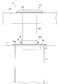
- FIG. 4 It is a block diagram which shows typically the filter cloth type dust collector with which the compressed air injection device which concerns on 1st Embodiment of this invention was attached.
- A is an enlarged plan view of an air circulation pipe and an air amplification device
- (b) is an enlarged side view of the air circulation pipe and the air amplification device. It is an expanded sectional view of an air circulation pipe and an air amplification device. It is an enlarged side view of the air amplification device periphery in the state where the compressed air injection device is attached to the filter cloth type dust collector.
- (A) is a side view of the cover member shown by FIG. 4, (b) is the top view.
- FIG. 6 It is a partial cross section enlarged side view of the air amplifier periphery in the state where the compressed air injection device concerning a 2nd embodiment of the present invention was attached to the filter cloth type dust collector.
- A is a side view of the air amplifying device to which the stopper shown in FIG. 6 is fixed, and (b) is a bottom view of the same. It is an enlarged side view of the air amplifier periphery in the state where the compressed air injection device concerning a 3rd embodiment of the present invention was attached to the filter cloth type dust collector.
- A) is a top view of the stopper and set screw shown in FIG. 6, (b) is the same side view.
- FIG. 10 is a side view of the second pipe to which the stopper shown in FIG. 10 is fixed
- (b) is a sectional view taken along the line CC of (a).
- (A) is a side view of the 2nd pipe
- (b) is sectional drawing which follows the DD line
- FIG. 16 is an enlarged view at a time point ta in FIG. 15. It is an enlarged view at the time tc in FIG.
- FIG. 1 is a configuration diagram schematically showing a filter cloth dust collector 100 to which a compressed air injection device 5 according to a first embodiment of the present invention is attached.
- a filter cloth type dust collector 100 includes a housing 1 and a plurality of filters 3 that collect dust and powder by filtering air that is disposed in the housing 1 and sent into the housing 1. And a compressed air injection device 5 that jets compressed air to the filter 3 in a pulsed manner to remove dust and powder adhering to the filter 3.
- the inside of the housing 1 is divided into a lower dust collection chamber 12 and an upper cleaning chamber 13 by a partition wall 11 in the vertical direction.
- the filter 3 has a ring-shaped upper end opening edge 31 (see FIG. 4) located at the upper end thereof attached to the partition wall 11, and the air flowing in the housing 1 from the dust collection chamber 12 side to the clean chamber 13 side. Collects dust and powder contained inside.
- Into the dust collection chamber 12 of the housing 1 is air introduction for introducing air A containing dust and powder from an incineration plant, a steel factory, a powder factory (all not shown) into the dust collection chamber 12.
- a tube 15 is connected.
- an air discharge pipe 16 that discharges air B that has been filtered and purified by the filter 3 from the clean chamber 13 is connected to the clean chamber 13 of the housing 1.
- An air suction device (not shown) is provided on the downstream side of the air discharge pipe 16 so that the purified air B in the clean chamber 13 is sucked to the outside.
- the lower part of the dust collection chamber 12 of the housing 1 is formed in a funnel shape, and a discharge port 17 is formed at the lower end of the housing 1.
- the dust and powder that have been removed from the filter 3 are configured to be discharged from the discharge port 17 to the outside.
- the filter 3 has a bottomed cylindrical shape, and is suspended from the partition wall 11 so that the upper end opening 32 (see FIG. 4) of the filter 3 faces the clean chamber 13.
- a plurality of rows in which six filters 3 are continuously arranged in the left and right (lateral) direction of the paper surface are arranged side by side in the depth direction of the paper surface.
- the number of installed filters 3 and the installed layout can be changed as appropriate.
- the filter 3 is configured by covering a bag-like filter cloth on the outside of a support frame having a cylindrical cage shape.
- a material for the filter cloth for example, a woven cloth or a non-woven cloth can be used.
- the filter cloth type dust collector 100 includes a differential pressure detection unit 14 that detects a difference between an upstream pressure and a downstream pressure in the air filtration direction of the filter 3 (hereinafter also referred to as “differential pressure”), and a compression. And a control unit (not shown) for controlling the operation of the filter cloth type dust collector 100 such as the operation of the air injection device 5.
- the differential pressure detector 14 includes a water surface on the dust collection chamber 12 side and a clean chamber enclosed in a U-shaped tube 19 having one end communicating with the dust collection chamber 12 and the other end communicating with the clean chamber 13. By detecting the altitude difference H from the 13th water surface, the differential pressure can be detected.
- the compressed air injection device 5 includes a compressed air supply unit 51 that supplies compressed air, an air circulation pipe 52 through which compressed air supplied from the compressed air supply part 51 circulates, and air sent from the air circulation pipe 52 to the outside. And a plurality of air amplifying devices 53 that amplify the air by attracting the air and inject the air onto the filter 3.
- the compressed air supply unit 51 includes, for example, a tank 54 in which compressed air is stored, a valve 55 for supplying compressed air to the air flow pipe 52 in a pulsed manner, and a supply that connects the tank 54 and the air flow pipe 52.
- a tube 56 is
- FIG. 2 (a) is an enlarged plan view of the air circulation pipe 52 and the air amplifying device 53
- FIG. 2 (b) is an enlarged side view of the air circulation pipe 52 and the air amplifying device 53
- FIG. 3 is an enlarged cross-sectional view of the air circulation pipe 52 and the air amplifying device 53.
- the air circulation pipe 52 is a pipe having a rectangular cross section.
- the cross-sectional shape of the air circulation pipe 52 is not particularly limited, and may be, for example, a square or a polygon.
- One end of the air circulation pipe 52 is provided with a connection port 57 connected to the supply pipe 56, and the other end of the air circulation pipe 52 (the end opposite to the connection port 57) is closed.
- the air circulation pipe 52 has an air outlet 58 through which air to be sent to the air amplifier 53 passes.
- the air amplifying device 53 includes an annular portion 59 in which an annular space S is formed, and a cylindrical delivery portion 60 that is connected to the annular portion 59.
- the annular portion 59 is configured by joining an upper wall portion 61 and a lower wall portion 62 at the outer peripheral end, for example, by caulking.
- the upper wall portion 61 has a curved cross section that is convex upward.
- the lower wall portion 62 includes a flat portion 63 having a substantially horizontal planar shape, and an R-shaped portion 64 having an R-shaped cross section extending from the inner peripheral edge of the flat portion 63.
- the annular space S is formed between the upper wall portion 61 and the lower wall portion 62.
- the lower wall 62 of the annular part 59 is provided with an air inlet 65 connected to the air outlet 58 of the air circulation pipe 52.
- the connection portion between the air outlet 58 and the air inlet 65 is sealed using the packing P.
- An annular injection hole 66 for injecting air introduced via the air inlet 65 is provided on the inner diameter side of the annular portion 59.
- the injection hole 66 is a slit nozzle formed as a gap between the inner peripheral portion of the upper wall portion 61 and the inner peripheral portion of the lower wall portion 62.
- the injection direction of the compressed air from the injection hole 66 is set obliquely downward toward the central axis of the delivery unit 60.
- the compressed air injection direction is set, for example, at an angle of 45 ° with respect to the central axis of the delivery unit 60, but is not limited thereto.
- the width W of the injection hole 66 is set to 0.3 mm or more and 2 mm or less, for example, it is not limited to this.
- the delivery part 60 is connected to the inner peripheral edge of the lower wall part 62 of the annular part 59, and the filter 3 (FIG. 4) together with the compressed air 71 injected from the injection hole 66 together with the attracted air 72. (See below).
- the delivery part 60 is formed integrally with the lower wall part 62 of the annular part 59.
- the delivery part 60 and the lower wall part 62 may be configured by being manufactured separately and then joined by welding or the like, for example.
- the compressed air injection device 5 includes a reinforcing member 67 disposed in parallel with the air circulation pipe 52.
- the air circulation pipe 52 and the reinforcing member 67 are joined to each other at both ends, so that strength and rigidity are improved.
- the delivery part 60 is disposed between the air circulation pipe 52 and the reinforcing member 67, and the annular part 59 is placed on the air circulation pipe 52 and the reinforcing member 67 and is held by a holding means (not shown).
- a holding means not shown
- the air flow pipe 52 and the reinforcing member 67 are made of, for example, metal, and here, iron (rust-proofing and baking coating) is used as a material.
- the air amplifying device 53 is made of, for example, metal or high-strength plastic, and here, stainless steel is used as the material.
- FIG. 4 is an enlarged side view of the periphery of the air amplifying device 53 in a state where the compressed air injection device 5 is attached to the filter cloth type dust collector 100.
- Fig.5 (a) is a side view of the cover member shown by FIG. 4,
- FIG.5 (b) is the same top view.
- the tip of the delivery unit 60 of the air amplifying device 53 extends into the filter 3.
- the depth at which the tip of the delivery part 60 enters the filter 3 is set to, for example, more than 0 mm and 50 mm or less, but may be changed as appropriate.
- a cover member 68 that covers the upper end opening 32 of the filter 3 is installed on the radially outer side of the delivery unit 60 of the air amplifying device 53.
- the cover member 68 is a ring-shaped plate body in which an opening hole 69 into which the delivery section 60 is inserted is formed at the center, and is placed on the upper end opening edge 31 of the filter 3.
- the outer diameter of the cover member 68 is set to be larger than the inner diameter of the upper end opening edge 31 of the filter 3, and the inner diameter of the cover member 68, that is, the diameter of the opening hole 69 is outside the sending section 60 of the air amplifying device 53. It is set slightly larger than the diameter. In other words, a certain amount of gap is formed between the inner surface of the opening hole 69 of the cover member 68 and the outer peripheral surface of the delivery section 60 of the air amplifying device 53 in consideration of assembly workability.
- the gap is set in the diametrical direction to be, for example, greater than 0 mm and 2 mm or less, but may be changed as appropriate.
- the cover member 68 is made of, for example, metal, and here, stainless steel is used as a material.
- the compressed air 70 supplied from the compressed air supply unit 51 (see FIG. 1) is injected from the annular injection hole 66.
- Compressed air 71 from the annular injection hole 66 flows along the inner wall surface of the cylindrical delivery part 60 by the Coanda effect, so that forced air is ejected from the delivery part 60 in a cylindrical shape.
- the cylindrical forced air is amplified by attracting external air 72 from above to the inside in the radial direction, and is injected into the filter 3 (see FIG. 1). Therefore, the compressed air 71 injected from the injection hole 66 is reliably amplified through the delivery unit 60 and is delivered almost straight and reaches the back of the filter 3.
- the pressure in the filter 3 sequentially increases from the back of the filter 3 toward the upper end opening 32.
- the tip of the sending part 60 extends inside the filter 3, and a cover member 68 that covers the upper end opening 32 of the filter 3 is installed outside the sending part 60 in the radial direction. Yes. Therefore, the pressure inside the filter 3 is suppressed by the cover member 68 from escaping from the upper end opening 32 of the filter 3 to the outside of the filter 3. For this reason, the filter 3 can be vibrated effectively without losing the filtered wind speed by the sufficient pressure and air volume of the compressed air, and dust and powder on the filter 3 can be removed. As described above, according to this embodiment, it is possible to provide the compressed air injection device 5 that can more surely remove dust and powder adhering to the filter 3 of the filter cloth type dust collector 100.
- FIG. 6 is a partial cross-sectional enlarged side view of the periphery of the air amplifying device 53 in a state where the compressed air injection device 5 according to the second embodiment of the present invention is attached to the filter cloth type dust collector 100.
- 7A is a side view of the air amplifying device 53 to which the stopper 75 shown in FIG. 6 is fixed, and
- FIG. 7B is a bottom view thereof.
- illustration of the air inlet 65 is omitted for simplification of the drawing.
- the compressed air injection device 5 includes the stopper 75 as a restricting means for restricting the upward movement of the cover member 68a.
- the cover member 68 a is formed with an opening hole 69 a into which the delivery part 60 is inserted at the center, and is placed on the upper end opening edge part 31 a of the filter 3.
- the stopper 75 is fixed to the outer peripheral surface of the delivery part 60 of the air amplifying device 53 by welding or the like, and extends obliquely from the lower end edge of the fixation part 76 toward the radially outer side of the delivery part 60. It is a bent rectangular plate having a regulating portion 77, and can function as a leaf spring. A plurality (three in this case) of stoppers 75 are provided on the outer peripheral surface of the delivery part 60 at equal angular intervals in the circumferential direction.
- the stopper 75 is preferably connected to the delivery unit 60 so that the regulating unit 77 is slightly deformed by urging the upper surface of the cover member 68a when the compressed air injection device 5 is attached to the filter cloth type dust collector 100.
- the fixed position is set.
- the cover member 68 floats due to its own weight, the frictional resistance between the inner surface of the opening hole 69 of the cover member 68 and the outer peripheral surface of the delivery section 60 of the air amplifying device 53, or the like.
- the rise is suppressed.
- the stopper 75 as the restricting means further suppresses the cover member 68a from floating upward from the upper end opening 32 of the filter 3. For this reason, it can suppress more effectively that the pressure in the filter 3 escapes from the upper end opening part 32 out of the filter 3.
- the cover member 68a of the second embodiment is set to be thinner than the cover member 68 of the first embodiment because the upward movement is restricted by the stopper 75.
- the cover member 68a abuts against the stopper 75, so that the cover member 68a can be further prevented from rising. Therefore, the upward movement of the cover member 68a can be restricted with a simple configuration. Further, the cover member 68a can be easily attached and detached, and the ease of maintenance work can be ensured.
- FIG. 8 is an enlarged side view of the periphery of the air amplifying device 53 in a state where the compressed air injection device 5 according to the third embodiment of the present invention is attached to the filter cloth type dust collector 100.
- FIG. 9A is a plan view of the stopper 78 and the set screw 79 shown in FIG. 6, and FIG. 9B is a side view thereof.
- the stopper 78 has a cylindrical shape into which the delivery part 60 of the air amplifying device 53 is inserted radially inward.
- a plurality (three in this case) of screw holes into which set screws 79 are screwed are formed at equal angular intervals in the circumferential direction.
- the stopper 78 is formed by tightening a set screw 79 at a position where the lower end surface of the stopper 78 contacts the upper surface of the cover member 68a in a state where the compressed air injection device 5 is attached to the filter cloth type dust collector 100. 60 is fixed. Also according to the third embodiment, it is possible to achieve the same operational effects as those of the second embodiment described above. Further, the stopper 78 can be firmly fixed to the delivery portion 60 in a state where the upper end opening 32 of the filter 3 is closed by the cover member 68a. Further, the upward movement of the cover member 68a can be uniformly restricted at each position in the circumferential direction by the cylindrical stopper 78.
- FIG. 10 is an enlarged side view of the periphery of the air amplifying device 53 in a state where the compressed air injection device 5 according to the fourth embodiment of the present invention is attached to the filter cloth type dust collector 100.
- 11A is a side view of the second pipe 82 to which the stopper 80 shown in FIG. 10 is fixed, and FIG. 11B is a cross-sectional view taken along the line CC in FIG. 11A.
- the sending section 60a of the air amplifying device 53 is arranged on the same axis and connected to be separable from each other. It has a tube 82.
- the second tube 82 has a cylindrical shape in which the first tube 81 is inserted radially inward.
- a plurality of screw holes are formed side by side at equal angular intervals in the circumferential direction.
- the stopper 80 is provided on the outer peripheral surface of the second pipe 82 by being fixed by welding or the like in a plurality (three in this case) arranged at equal angular intervals in the circumferential direction.
- the second pipe 82 is tightened by tightening a set screw 83 at a position where the lower end surface of the stopper 80 contacts the upper surface of the cover member 68a. It is fixed to one tube 81. Further, it is preferable to use a fixing nut 84 for preventing loosening (the same applies to other embodiments).
- the connection method between the first pipe 81 and the second pipe 82 is not limited to the above-described method.
- the fourth embodiment has a plurality of pipes (here, the first pipe 81 and the second pipe 82) that are coaxially and detachably connected to each other.
- a compressed air injection device that has a short delivery section of the air amplifier and does not reach the filter 3 is already attached to the filter cloth dust collector 100, the tip of the delivery section is extended by extending the length of the delivery section. Can be changed to a state of being stretched inside the filter 3. Therefore, the compressed air injection device 5 according to the present embodiment can be quickly implemented at low cost by using existing equipment.
- FIG. 12A is a side view of the second pipe 82 to which the stopper 85 according to a modification of the fourth embodiment is fixed
- FIG. 12B is a cross section taken along the line DD in FIG. FIG.
- the stopper 85 has a ring shape into which the second pipe 82 is inserted radially inward, and is fixed to the outer peripheral surface of the second pipe 82 by welding or the like. Also by such a modification, the same effect as the above-described fourth embodiment can be obtained. Further, the ring-shaped stopper 85 can uniformly restrict the upward movement of the cover member 68a at each position in the circumferential direction.
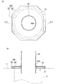
- FIG. 13 is an enlarged side view of the periphery of the air amplifying device 53 in a state where the compressed air injection device 5 according to the fifth embodiment of the present invention is attached to the filter cloth type dust collector 100.
- FIG. 14A is a plan view of the second pipe 82 to which the cover member 68b shown in FIG. 13 is fixed, and
- FIG. 14B is a cross-sectional view taken along line EE of FIG. .
- the cover member 68b has a plate-like portion 86 composed of a horizontal flat plate and a cross section extending downward from two opposite sides of the outer peripheral edge of the plate-like portion 86. And an engagement portion 87 having a letter shape.
- the plate-like portion 86 has an octagonal shape in plan view, but is not limited thereto, and may have another polygonal shape or a substantially circular shape.
- the inner peripheral part of the opening hole 69b and the outer peripheral part of the second pipe 82 are entirely or partially welded in a state where the second pipe 82 of the delivery part 60a is inserted into the opening hole 69b formed in the center of the cover member 68b.
- the cover member 68b is fixed to the second pipe 82 of the delivery part 60a.
- the engaging portion 87 of the cover member 68 b engages with the upper end opening edge 31 by the L-shaped tip of the engaging member 87 entering under the upper end opening edge 31 of the filter 3.
- the cover member 68b is fixed to the upper end opening edge 31 of the filter 3, and the engaging portion 87 functions as a restricting means for restricting the upward movement of the cover member 68b.
- the plate-like portion 86 of the cover member 68b covers the upper end opening 32 of the filter 3, and the second pipe 82 of the delivery portion 60a is supported by the upper end opening edge 31 of the filter 3 via the cover member 68b. ing. Therefore, it is not necessary to fix the first pipe 81 and the second pipe 82 with a set screw or the like.
- the same operational effects as those of the fourth embodiment described above can be achieved. Further, the fifth embodiment further provides the following operational effects. That is, since the cover member 68b and the second pipe 82 of the delivery section 60a can be configured in advance, handling of the parts is facilitated, and the operation of attaching the compressed air injection device 5 to the filter cloth type dust collector 100 can be performed quickly and easily. It can be done easily. Further, the cover member 68b is fixed to the upper end opening edge 31 of the filter 3, whereby the cover member 68b can be prevented from being lifted. And since the upper end opening part 32 of the filter 3 is closed by the cover member 68b, it can suppress more reliably that the pressure in the filter 3 escapes out of the filter 3 from the upper end opening part 32. FIG.
- this invention is not limited to the structure described in each above-mentioned embodiment, The combination thru
- the cover member 68 is placed on the upper end opening edge 31 of the filter 3 and is not fixed, but is not limited thereto.
- the cover member 68 may be fixed to the delivery unit 60 of the air amplifying device 53 by fixing means such as welding or screw fastening. In this configuration, the cover member 68 is fixed to the delivery unit 60, whereby the cover member 68 can be prevented from being lifted. In this case, a certain amount of gap may be formed between the lower surface of the cover member 68 and the upper surface of the upper end opening edge 31 of the filter 3.
- the outer diameter of the cover member 68 may be set slightly smaller than the inner diameter of the upper end opening edge 31 of the filter 3.
- the cover member 68 may be fixed to the upper end opening edge 31 of the filter 3 by fixing means such as screw fastening. In this configuration, the cover member 68 is fixed to the upper end opening edge 31 of the filter 3, whereby the cover member 68 can be prevented from rising. In addition, since the upper end opening 32 of the filter 3 is closed by the cover member 68, it is possible to more reliably suppress the pressure in the filter 3 from escaping from the upper end opening 32 to the outside of the filter 3.
- the outer diameter of the delivery section 60 may be set so that the difference from the inner diameter of the filter 3 is 5 mm or less, preferably 3 mm or less. Also with this configuration, the pressure inside the filter 3 can be prevented from escaping from the upper end opening 32 to the outside of the filter 3. Therefore, with the configuration in which the cover members 68, 68a, 68b are omitted, it is possible to provide the compressed air injection device 5 that can more reliably remove dust and powder attached to the filter 3 of the filter cloth type dust collector 100.
- FIG. 15 is a graph showing a temporal change in the differential pressure, which is the difference between the upstream pressure and the downstream pressure in the air filtration direction of the filter 3.
- FIG. 16 is an enlarged view at time ta in FIG.
- FIG. 17 is an enlarged view at time tc in FIG.
- time points t1, t2, t3, and t4 correspond to dates at one-month intervals.
- This embodiment is in the middle of a state in which an existing compressed air injection device that has a short delivery section of the air amplifying device and does not reach the filter 3 is attached to the filter cloth type dust collector 100 and operated (time tb in FIG. 15). It changed to the compressed air injection device 5 concerning. That is, it implemented about the modification (refer FIG. 12) of above-described 4th Embodiment using the existing installation.
- a filter 3 having an outer diameter of 165 mm and a length of 2700 mm was used.
- As the valve 55 a diaphragm valve 40A was used.
- the filtration wind speed was a design value of 2 m / min and an actual measurement value of 1.5 m / min.
- the compressed air ejecting device 5 is provided with six rows of six amplifying devices 53 arranged continuously in the left and right (lateral) direction of the paper surface, and arranged in six rows in the depth direction of the paper surface. A thing was used (6 rows and 6 rows).
- the compressed air pressure in the tank 54 was 0.5 MPa.
- the compressed air injection time was set to 0.1 seconds.
- the differential pressure which is the difference in pressure between the upstream side and the downstream side of the filter 3 during operation, is 180 to The pressure dropped from about 190 mmAq (about 1.8 to 1.9 kPa) to about 120 to 130 mmAq (about 1.2 to 1.3 kPa).
- a state such as clogging of the filter cloth type dust collector 100 can be determined by a differential pressure during operation.
- the differential pressure becomes about 200 mmAq (about 2 kPa) or more, maintenance such as cleaning or replacement is required. 0.5 kPa) or less is preferable. Therefore, it was confirmed that the existing equipment, which was in need of maintenance soon, applied the present embodiment to reduce the differential pressure to a level where there was no problem in operation.
- FIG. 16 shows a temporal change in the differential pressure before application of the present embodiment (time point ta in FIG. 15).
- FIG. 17 shows a temporal change in the differential pressure after application of the present embodiment (time tc in FIG. 15). As shown in FIG.
Landscapes
- Chemical & Material Sciences (AREA)
- Chemical Kinetics & Catalysis (AREA)
- Filtering Of Dispersed Particles In Gases (AREA)
Abstract
L'invention concerne un dispositif d'injection d'air comprimé apte à éliminer, d'une manière plus certaine, la poussière et la poudre adhérant à un filtre d'un collecteur de poussière de type tissu filtrant. Le dispositif d'injection d'air comprimé (5) comprend un tube d'écoulement d'air (52) et un dispositif d'amplification d'air (53). Le dispositif d'amplification d'air (53) comprend une partie annulaire (59) et une partie d'éjection tubulaire (60a). L'extrémité avant de la partie d'éjection (60a) s'étend vers l'intérieur d'un filtre (3), et un élément de couvercle (68a) recouvrant une partie d'ouverture d'extrémité supérieure (32) du filtre (3) est agencé sur le côté externe de la partie d'éjection (60a), dans la direction radiale. La partie d'éjection (60a) comprend un premier tube (81) positionné sur son côté supérieur et un second tube (82) positionné sur son côté inférieur, le premier tube (81) et le second tube (82) étant reliés l'un à l'autre de façon à être librement séparables l'un de l'autre. Des butées (80) sont fixées sur la surface circonférentielle externe du second tube (82), et le second tube (82) est fixé, par fixation de vis, au premier tube (81) dans une position dans laquelle les surfaces d'extrémité inférieures des butées (80) sont en contact avec la surface supérieure de l'élément de couvercle (68a).
Applications Claiming Priority (2)
| Application Number | Priority Date | Filing Date | Title |
|---|---|---|---|
| JP2015245978A JP6155534B2 (ja) | 2015-12-17 | 2015-12-17 | 圧縮空気噴射装置 |
| JP2015-245978 | 2015-12-17 |
Publications (1)
| Publication Number | Publication Date |
|---|---|
| WO2017104595A1 true WO2017104595A1 (fr) | 2017-06-22 |
Family
ID=59056564
Family Applications (1)
| Application Number | Title | Priority Date | Filing Date |
|---|---|---|---|
| PCT/JP2016/086852 Ceased WO2017104595A1 (fr) | 2015-12-17 | 2016-12-12 | Dispositif d'injection d'air comprimé |
Country Status (3)
| Country | Link |
|---|---|
| JP (1) | JP6155534B2 (fr) |
| TW (1) | TW201726228A (fr) |
| WO (1) | WO2017104595A1 (fr) |
Cited By (1)
| Publication number | Priority date | Publication date | Assignee | Title |
|---|---|---|---|---|
| USD918654S1 (en) | 2019-06-06 | 2021-05-11 | Sharkninja Operating Llc | Grill plate |
Families Citing this family (5)
| Publication number | Priority date | Publication date | Assignee | Title |
|---|---|---|---|---|
| JP2019167932A (ja) * | 2018-03-26 | 2019-10-03 | いすゞ自動車株式会社 | サージ回避システム及びその制御方法 |
| CN110840329A (zh) * | 2019-11-28 | 2020-02-28 | 安徽富坤机械设备有限公司 | 一种吸尘器集尘装置 |
| JP2023078511A (ja) * | 2021-11-26 | 2023-06-07 | 東北電機鉄工株式会社 | バグフィルター式集塵機 |
| JP7638533B2 (ja) * | 2022-10-25 | 2025-03-04 | 株式会社不二製作所 | ブラスト加工装置における集塵機の制御方法及びブラスト加工装置 |
| CN121082022B (zh) * | 2025-10-31 | 2026-04-14 | 中矿和创环境科技(山东)有限公司 | 一种方便拆卸更换过滤袋的除尘装置 |
Citations (4)
| Publication number | Priority date | Publication date | Assignee | Title |
|---|---|---|---|---|
| JPS5037067A (fr) * | 1973-06-23 | 1975-04-07 | ||
| JPH10137528A (ja) * | 1996-11-12 | 1998-05-26 | Power Reactor & Nuclear Fuel Dev Corp | サイクロン式集塵装置 |
| JP2008115847A (ja) * | 2006-11-01 | 2008-05-22 | Kwang Sup Cho | 空気増幅器を利用した圧縮空気噴射装置 |
| JP2013116466A (ja) * | 2011-11-01 | 2013-06-13 | Total Business Solution:Kk | コアンダインジェクター |
Family Cites Families (3)
| Publication number | Priority date | Publication date | Assignee | Title |
|---|---|---|---|---|
| DE3341786A1 (de) * | 1983-11-17 | 1985-06-20 | Delbag-Luftfilter Gmbh, 1000 Berlin | Mit druckluft abreinigbare filteranlage zur abscheidung von staub oder sand aus der luft |
| JP4200671B2 (ja) * | 2000-12-04 | 2008-12-24 | 株式会社日立プラントテクノロジー | 集塵装置 |
| JP2008296128A (ja) * | 2007-05-31 | 2008-12-11 | Nippon Spindle Mfg Co Ltd | バグ式集塵機 |
-
2015
- 2015-12-17 JP JP2015245978A patent/JP6155534B2/ja active Active
-
2016
- 2016-12-12 WO PCT/JP2016/086852 patent/WO2017104595A1/fr not_active Ceased
- 2016-12-16 TW TW105141681A patent/TW201726228A/zh unknown
Patent Citations (4)
| Publication number | Priority date | Publication date | Assignee | Title |
|---|---|---|---|---|
| JPS5037067A (fr) * | 1973-06-23 | 1975-04-07 | ||
| JPH10137528A (ja) * | 1996-11-12 | 1998-05-26 | Power Reactor & Nuclear Fuel Dev Corp | サイクロン式集塵装置 |
| JP2008115847A (ja) * | 2006-11-01 | 2008-05-22 | Kwang Sup Cho | 空気増幅器を利用した圧縮空気噴射装置 |
| JP2013116466A (ja) * | 2011-11-01 | 2013-06-13 | Total Business Solution:Kk | コアンダインジェクター |
Cited By (1)
| Publication number | Priority date | Publication date | Assignee | Title |
|---|---|---|---|---|
| USD918654S1 (en) | 2019-06-06 | 2021-05-11 | Sharkninja Operating Llc | Grill plate |
Also Published As
| Publication number | Publication date |
|---|---|
| TW201726228A (zh) | 2017-08-01 |
| JP6155534B2 (ja) | 2017-07-05 |
| JP2017109176A (ja) | 2017-06-22 |
Similar Documents
| Publication | Publication Date | Title |
|---|---|---|
| JP6155534B2 (ja) | 圧縮空気噴射装置 | |
| JP6607880B2 (ja) | 圧縮空気噴射装置 | |
| US7585343B2 (en) | Filter cleaning system and method | |
| JP2008238166A (ja) | フィルタ洗浄制御システム及び方法 | |
| CZ2011370A3 (cs) | Systém a zpusob pro odstranování cásticové hmoty z náplne filtru | |
| SE513489C2 (sv) | Vätskefilter | |
| US20130125754A1 (en) | Systems and methods for improved baghouse filters | |
| US20080022855A1 (en) | Filter cleaning system and method | |
| JP2008279405A (ja) | バグ式集塵機 | |
| KR101495057B1 (ko) | 이동식 필터 백 재생장치 | |
| US10814262B2 (en) | Flow control device for a self-cleaning gas filtration system | |
| US10245539B2 (en) | Virtual impactor filter assembly and method | |
| KR101643574B1 (ko) | 백필터 탈진용 분사노즐 | |
| JP6499779B2 (ja) | バグフィルター用空気増幅装置および該バグフィルター用空気増幅装置を用いたバグフィルター用空気増幅システム | |
| JP4593463B2 (ja) | 集塵装置 | |
| US11071931B1 (en) | Self-cleaning inline filter | |
| KR200473565Y1 (ko) | 화재감지기용 공기여과장치 | |
| JP6090797B2 (ja) | 集塵装置 | |
| KR20160007264A (ko) | 이동식 필터 백 재생장치 | |
| KR20160007263A (ko) | 이동식 필터 백 재생장치 | |
| JP5969686B2 (ja) | バグフィルター用空気増幅装置および該バグフィルター用空気増幅装置を用いたバグフィルター用空気増幅システム | |
| JP2014180609A (ja) | 集塵装置 | |
| JP2010227773A (ja) | 集塵機 | |
| JP2019093368A (ja) | バグフィルターの逆洗に用いる空気増幅装置を独立搭載により備えた集塵装置 | |
| KR20160007270A (ko) | 이동식 필터 백 재생 방법 |
Legal Events
| Date | Code | Title | Description |
|---|---|---|---|
| 121 | Ep: the epo has been informed by wipo that ep was designated in this application |
Ref document number: 16875572 Country of ref document: EP Kind code of ref document: A1 |
|
| NENP | Non-entry into the national phase |
Ref country code: DE |
|
| 122 | Ep: pct application non-entry in european phase |
Ref document number: 16875572 Country of ref document: EP Kind code of ref document: A1 |