WO2017104659A1 - Tube à rayons x et spectromètre à rayons x - Google Patents
Tube à rayons x et spectromètre à rayons x Download PDFInfo
- Publication number
- WO2017104659A1 WO2017104659A1 PCT/JP2016/087055 JP2016087055W WO2017104659A1 WO 2017104659 A1 WO2017104659 A1 WO 2017104659A1 JP 2016087055 W JP2016087055 W JP 2016087055W WO 2017104659 A1 WO2017104659 A1 WO 2017104659A1
- Authority
- WO
- WIPO (PCT)
- Prior art keywords
- ray
- target
- thin film
- sample
- vacuum vessel
- Prior art date
- Legal status (The legal status is an assumption and is not a legal conclusion. Google has not performed a legal analysis and makes no representation as to the accuracy of the status listed.)
- Ceased
Links
Images

Classifications
-
- G—PHYSICS
- G01—MEASURING; TESTING
- G01N—INVESTIGATING OR ANALYSING MATERIALS BY DETERMINING THEIR CHEMICAL OR PHYSICAL PROPERTIES
- G01N23/00—Investigating or analysing materials by the use of wave or particle radiation, e.g. X-rays or neutrons, not covered by groups G01N3/00 – G01N17/00, G01N21/00 or G01N22/00
- G01N23/02—Investigating or analysing materials by the use of wave or particle radiation, e.g. X-rays or neutrons, not covered by groups G01N3/00 – G01N17/00, G01N21/00 or G01N22/00 by transmitting the radiation through the material
- G01N23/04—Investigating or analysing materials by the use of wave or particle radiation, e.g. X-rays or neutrons, not covered by groups G01N3/00 – G01N17/00, G01N21/00 or G01N22/00 by transmitting the radiation through the material and forming images of the material
-
- H—ELECTRICITY
- H01—ELECTRIC ELEMENTS
- H01J—ELECTRIC DISCHARGE TUBES OR DISCHARGE LAMPS
- H01J35/00—X-ray tubes
- H01J35/02—Details
- H01J35/16—Vessels; Containers; Shields associated therewith
- H01J35/18—Windows
- H01J35/186—Windows used as targets or X-ray converters
-
- G—PHYSICS
- G01—MEASURING; TESTING
- G01N—INVESTIGATING OR ANALYSING MATERIALS BY DETERMINING THEIR CHEMICAL OR PHYSICAL PROPERTIES
- G01N23/00—Investigating or analysing materials by the use of wave or particle radiation, e.g. X-rays or neutrons, not covered by groups G01N3/00 – G01N17/00, G01N21/00 or G01N22/00
- G01N23/20—Investigating or analysing materials by the use of wave or particle radiation, e.g. X-rays or neutrons, not covered by groups G01N3/00 – G01N17/00, G01N21/00 or G01N22/00 by using diffraction of the radiation by the materials, e.g. for investigating crystal structure; by using scattering of the radiation by the materials, e.g. for investigating non-crystalline materials; by using reflection of the radiation by the materials
- G01N23/207—Diffractometry using detectors, e.g. using a probe in a central position and one or more displaceable detectors in circumferential positions
-
- G—PHYSICS
- G01—MEASURING; TESTING
- G01N—INVESTIGATING OR ANALYSING MATERIALS BY DETERMINING THEIR CHEMICAL OR PHYSICAL PROPERTIES
- G01N23/00—Investigating or analysing materials by the use of wave or particle radiation, e.g. X-rays or neutrons, not covered by groups G01N3/00 – G01N17/00, G01N21/00 or G01N22/00
- G01N23/22—Investigating or analysing materials by the use of wave or particle radiation, e.g. X-rays or neutrons, not covered by groups G01N3/00 – G01N17/00, G01N21/00 or G01N22/00 by measuring secondary emission from the material
- G01N23/223—Investigating or analysing materials by the use of wave or particle radiation, e.g. X-rays or neutrons, not covered by groups G01N3/00 – G01N17/00, G01N21/00 or G01N22/00 by measuring secondary emission from the material by irradiating the sample with X-rays or gamma-rays and by measuring X-ray fluorescence
Definitions
- the present invention relates to an X-ray tube configured to irradiate an electron beam onto a target placed in a vacuum vessel and to emit X-rays from the target, and an X-ray analyzer using the X-ray tube It is about.
- the X-ray tube 100A irradiates an electron beam E generated from a cathode 3A provided in a vacuum vessel 1A to a target thin film 51A serving as an anode, and then emits X-rays from the target thin film 51A. It is configured to generate XR.
- the X-ray tube 100A shown in FIG. 7 and Patent Document 1 is a vacuum vessel 1A in which the inside is maintained at a predetermined degree of vacuum, and a diamond product provided so as to prevent the opening of the vacuum vessel 1A.
- the X-ray tube 100A is a so-called microfocus X-ray tube configured such that the electron beam EB forms a minute image on the target thin film 51A.
- the obtained captured image is obtained by bringing the sample S to be imaged as close as possible to the target thin film 51A where X-rays are generated. Resolution and brightness can be improved. Therefore, the target thin film 51A is provided in the vicinity of the X-ray transmission window so as to reduce the distance from the sample.
- the sample S when the sample S is disposed in the atmospheric pressure, there is a pressure difference between the inside and outside of the X-ray tube 100A, so that the X-ray transmission window plate 2A is recessed toward the inside of the vacuum vessel 1A. I will bend. At this time, the target thin film 51A formed integrally with the X-ray transmission window plate 2A is also bent so as to be recessed inward.
- the distance between the target thin film 51A and the sample S is maintained larger than the designed distance, and X-ray transmission is maintained. It causes the resolution of the image to be constantly reduced.
- the target thin film 51A is elastically deformed, the X-ray tube 100A is opened to the atmosphere for maintenance and the like, and therefore, the target thin film 51A is repeatedly stressed by deformation and restoration, The target thin film 51A may be deteriorated or destroyed at an early stage.
- the present invention has been made in view of the above-described problems, and can optimize the separation distance between the sample and the target. For example, the resolution and brightness of a captured image based on X-rays can be increased.
- An object of the present invention is to provide an X-ray tube that can be used, and an X-ray analyzer using the X-ray tube.
- the X-ray tube according to the present invention is provided inside the vacuum vessel, and separates the target mechanism that receives an electron beam and emits X-rays, and the target mechanism so as to partition the inside and outside of the vacuum vessel.
- an X-ray permeable membrane that can transmit X-rays emitted from the target mechanism, and the X-ray permeable membrane is disposed inside the vacuum vessel when the inside of the vacuum vessel has a predetermined degree of vacuum. It is configured to bend and approach or contact the target mechanism.
- the load based on the pressure difference can be borne mainly by the X-ray permeable membrane.
- the X-ray permeable membrane and the target mechanism are configured separately, deformation of the X-ray permeable membrane is hardly transmitted to the target mechanism. Therefore, it is possible to prevent the target mechanism from being deformed in such a manner that almost no load is applied to the target mechanism.
- the X-ray permeable membrane is configured to bend toward the inside of the vacuum vessel when the inside of the vacuum vessel has a predetermined degree of vacuum, the X-ray transmissive membrane is close to or in contact with the target mechanism.
- the distance between the sample to be analyzed arranged outside the membrane and the target mechanism can be reduced.
- the target mechanism hardly deforms, the distance between the sample and the target mechanism can be kept at a designed value.
- the target mechanism is hardly deformed, a repeated load due to repeated deformation and restoration is small, and the target mechanism can have a long life.
- the outer surface of the X-ray transmission film is a sample mounting surface on which a sample to be irradiated with X-rays is mounted, and the inner surface of the X-ray transmission film is an opposing surface that is in proximity to or in contact with the target mechanism. If it is.
- the distance between the sample and the location where the X-rays are actually generated in the target mechanism can be made about the thickness of the X-ray transmission film, and the resolution and brightness in the X-ray image of the sample can be further improved.
- the target mechanism has a target thin film made of metal and a target in which the target thin film is arranged at a position spaced apart from the X-ray transmission film when there is no pressure difference between the inside and outside of the vacuum vessel. What is necessary is just to be provided with the support body.
- the separation distance between the X-ray permeable film and the target thin film is substantially the same value as the amount of deformation of the X-ray permeable film that occurs in the X-ray transmissive film when the inside of the vacuum vessel has a predetermined degree of vacuum. It only has to be set.
- the traveling direction of the X-rays emitted from the target thin film is limited to a predetermined direction to prevent a large amount of primary X-rays generated in the target thin film from entering the detector, for example, secondary X-rays generated in the sample
- the target mechanism includes a target thin film made of metal and a vacuum vessel. When there is no internal and external pressure difference, the target thin film is disposed between the target thin film at a position spaced apart from the X-ray transmissive film by a predetermined distance, the X-ray transmissive film, and the target thin film.
- an intervening body that regulates the traveling direction of X-rays generated in the thin film in a predetermined direction, and the X-ray permeable film contacts the intervening body when the inside of the vacuum vessel has a predetermined degree of vacuum. What is necessary is just to be comprised so that it may do.
- the X-ray transmission film is made of an elastic material formed of polyimide. Any film may be used.
- the area of the X-ray transmissive film that deforms to the inside of the vacuum vessel is determined by the target mechanism. As long as it is larger than the area on which the electron beam is incident.
- the X-ray transmissive film may be provided so as to be movable.
- an X-ray detector for detecting X-rays generated from a sample
- a signal processing unit for generating an X-ray spectrum based on the output of the detector
- the signal processing unit If the X-ray analyzer includes an analysis unit that performs qualitative analysis or quantitative analysis of the sample based on the generated X-ray spectrum, the X-ray generation position in the target mechanism, the sample to be imaged, It is possible to obtain an image with high resolution and brightness.
- an optical microscope provided so as to capture the outer surface on the X-ray transmission film in the field of view, and an element at each position of the sample What is necessary is just to further include an imaging unit that generates image data in which the distribution is mapped.
- the distance between the sample and the target mechanism can be optimized at the time of X-ray irradiation. Brightness and the like can be improved.
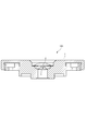
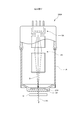
- the schematic diagram which shows the X-ray tube and X-ray analyzer which concern on 1st Embodiment of this invention.
- the typical cross-sectional enlarged view which expanded the front-end
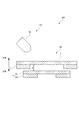
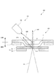
- the typical cross-sectional enlarged view which shows the structure of the X-ray permeable film and target mechanism in case the X-ray tube which concerns on 1st Embodiment is not evacuated.
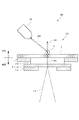
- the typical cross-sectional enlarged view which shows the structure of the X-ray permeable film and target mechanism in case the vacuum of the X-ray tube which concerns on 1st Embodiment is carried out.
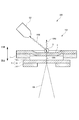
- the typical cross-sectional enlarged view which shows the structure of the X-ray tube which concerns on 2nd Embodiment of this invention.
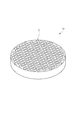
- the typical perspective view which shows the structure of the capillary plate of the X-ray tube which concerns on 2nd Embodiment.
- the typical cross-sectional enlarged view which shows the structure of the X-ray tube in the modification of 2nd Embodiment.
- the X-ray tube 100 and the X-ray analyzer 200 according to the first embodiment of the present invention will be described with reference to FIGS.
- the X-ray tube 100 of the first embodiment is a microfocus X-ray source configured so that the focal diameter of the primary X-ray XR1 is about several ⁇ m.
- the X-ray analysis apparatus 200 of the first embodiment includes the X-ray tube 100, a detector system 101, a control unit 7, a calculation mechanism 8, and a display 9, as shown in FIG. This is an inverted X-ray analyzer 200 configured such that the X-ray tube 100 emits a primary X-ray XR1 vertically upward.
- a sample S to be X-ray analyzed is directly placed on an X-ray transmission window portion formed on the top surface of the X-ray tube 100, and secondary X-ray XR2 generated in the sample S is obtained. Is detected and the sample S is analyzed.
- the X-ray tube 100 is provided as shown in FIG. 1 so as to partition the inside and outside of the vacuum container 1, and an X-ray transmission film 2 that forms an X-ray transmission window; At least the electron beam source 3, the beam optical system 4, and the target mechanism 5 including the target thin film 51 provided inside the vacuum container 1 are provided.
- the sample S and the target are sandwiched between the X-ray transmissive film 2 in a state where the inside is maintained at a predetermined degree of vacuum and the sample X is irradiated with the primary X-ray XR1.
- the thin film 51 is adjacent.
- the vacuum vessel 1 is connected to a vacuum pump 6, and the inside of the vacuum vessel 1 is maintained at a predetermined degree of vacuum when the sample S is irradiated with the primary X-ray XR1. As shown in FIGS. 2 and 3, the vacuum vessel 1 is provided with the X-ray permeable film 2 detachably on the top surface.
- the X-ray permeable membrane 2 has a membrane structure as shown in the enlarged view of FIG. 3, and the inside of the vacuum vessel 1 is not evacuated, and the pressure is approximately the same as the atmospheric pressure.
- the target mechanism 5 is provided as a separate body so as not to contact the target mechanism 5.
- the X-ray transmission film 2 is moved to the inside of the vacuum vessel 1.
- the opposing surface which is the inner surface, is in direct contact with the target mechanism 5. As shown in FIG.
- the sample S when the sample S is, for example, in the form of particles, the sample S can be placed in the recess on the outer surface that is recessed on the outer surface of the X-ray permeable membrane 2.
- the sample S is not limited to a particulate material, and may be a solid or a liquid.
- the X-ray permeable film 2 is made of, for example, polyimide having a predetermined elasticity, and a material that does not have a chemical reaction with the target sample S and has X-ray permeability is selected.
- the electron beam source 3 is configured such that a voltage is applied to the target thin film 51 as an anode, and an electron beam EB is emitted to the target thin film 51.
- the beam optical system 4 is composed of, for example, a plurality of electromagnets as shown in FIG. 1, deflects the electron beam EB emitted from the electron beam source 3, and is irradiated on the target thin film 51 with a diameter of about several ⁇ m. So that the light is condensed.
- the irradiation position of the electron beam EB on the target thin film 51 can be scanned by changing the magnetic field or electric field formed in the beam optical system 4.
- the target mechanism 5 receives the electron beam EB emitted from the electron beam source 3 and emits primary X-rays XR1 in the direction of the X-ray transmission film 2 as shown in FIGS. More specifically, in the first embodiment, the target mechanism 5 separates the target thin film 51 and the target thin film 51 from the X-ray transmission film 2 by a predetermined distance when there is no pressure difference between the inside and outside of the vacuum vessel 1. And a target support 52 for disposing the target thin film 51 at the position.
- the target thin film 51 is a thin film made of a metal such as tungsten, for example, and generates an X-ray XR upon receiving an electron beam EB.
- One surface of the thin film is supported from the inside of the vacuum vessel 1 by the target support 52 so as to face the inner surface of the X-ray permeable membrane 2.
- This target thin film 51 is also configured to be replaceable when it deteriorates.
- the target support 52 has a substantially circular opening that reaches the target thin film 51 when the electron beam EB is incident on the center thereof. This opening is formed coaxially smaller than the opening in which the X-ray transmission film 2 is provided in the vacuum vessel 1.
- the separation distance d between the target thin film 51 and the X-ray transmission film 2 shown in FIG. 3 when there is no pressure difference inside and outside the vacuum vessel 1 will be described.
- the X-ray permeable membrane 2 bends inwardly due to an evenly distributed load due to a pressure difference between the inside and outside.
- the maximum displacement amount on the target thin film 51 side of the X-ray transmission film 2 and the separation distance d are set to be substantially the same value. That is, as shown in FIG. 4, even when the X-ray transmissive film 2 is deformed due to a pressure difference, the X-ray transmissive film 2 only touches the target thin film 51 and presses against the target thin film 51.
- the load is hardly applied. Therefore, in any state shown in FIGS. 3 and 4, the target thin film 51 is maintained in substantially the same shape, and is configured so as to hardly deform. Further, as shown in FIG. 4, the flat portion on the inner side surface of the X-ray transmissive film 2 after deformation substantially coincides with the opening portion of the target support 52. Therefore, even if the electron beam EB is irradiated on any part of the target thin film 51, the primary X-ray XR1 is incident on the X-ray transmission film 2 in substantially the same state.
- the detector system 101 includes a first X-ray detector D1 provided along the axial direction, and the axial direction.
- a second X-ray detector D2 provided obliquely and an optical microscope provided so that the outer surface of the X-ray transmission film 2 is captured in the field of view.
- the second X-ray detector D2 is provided obliquely with respect to the traveling direction of the main primary X-ray XR1, and can mainly detect fluorescent X-rays that are the secondary X-ray XR2 excited in the sample S. is there. Even in the second X-ray detector D2 provided in this way, some of the primary X-rays XR1 generated in the target thin film 51 that travel obliquely with respect to the axial direction are incident.
- the detector system 101 detects the fluorescent X-rays excited by the sample S as the secondary X-ray XR2.
- the detector system 101 detects other types of secondary X-rays XR2. May be.
- the secondary X-ray XR2 detected by the detector system 101 may be a scattered X-ray in which the primary X-ray XR1 is scattered in the sample S or a transmitted X-ray in which the primary X-ray XR1 is transmitted through the sample S. .
- the control unit 7 controls the operation of the X-ray tube 100, the vacuum pump 6, the detector system 101, and the arithmetic mechanism 8.
- the arithmetic mechanism 8 is a computer including, for example, a CPU, a memory, an A / D / D / A converter, an input / output means, and the like so that the X-ray analyzer program stored in the memory is executed. It is configured.
- the calculation mechanism 8 exhibits at least functions as a signal processing unit 81, an analysis unit 82, and an imaging unit 83 by executing programs and cooperation of various devices.
- the signal processing unit 81 generates a spectrum of the secondary X-ray XR2 generated from the sample S based on, for example, the output of the first X-ray detector D1 or the second X-ray detector D2.
- the analysis unit 82 performs qualitative analysis or quantitative analysis of the sample S based on the spectrum of the secondary X-ray XR2 generated in the signal processing unit. For example, the analysis unit 82 specifies the composition of the sample S from the wavelength of fluorescent X-rays generated from the sample S, and specifies the ratio of the constituent substances from the intensity.
- the imaging unit 83 provides information on the position where the X-ray is irradiated in the sample S obtained by the optical microscope MS, and the qualitative analysis of the element output by the analysis unit 82 regarding the position irradiated with the X-ray. Based on the result or the quantitative analysis result, image data is generated by mapping the element distribution for each position of the sample S and displayed on the display unit 9.
- the pressure in the vacuum vessel 1 is a predetermined pressure, and the primary X-ray XR1 is irradiated to the sample S.
- the resolution and brightness of the X-ray transmission image of the sample S obtained based on the output from the detector system 101 can be set to the highest state.
- the X-ray permeable membrane 2 and the target mechanism 5 are provided separately from each other, the load generated when there is a pressure difference inside and outside the vacuum vessel 1 is borne only by the X-ray permeable membrane 2.
- the target thin film 51 can be hardly loaded. For this reason, the target thin film 51 is plastically deformed, for example, is dented toward the electron beam source 3, and a gap is generated between the X-ray transmission film 2 and the target thin film 51, so that the sample S and the target thin film 51 It is possible to prevent the distance between them from changing from the design value in the direction of increasing.
- the target thin film 51 Even if the pressure in the vacuum vessel 1 repeatedly fluctuates between atmospheric pressure and a predetermined degree of vacuum, for example, due to maintenance or the like, the target thin film 51 hardly fluctuates in load. It is difficult to cause deterioration and destruction due to the above, and the life as the target thin film 51 can be improved as compared with the conventional case.
- the target thin film and the sample are tried to be as close as possible in the conventional X-ray tube, the target is caused by the pressure difference between the inside and outside of the vacuum vessel. A large deformation occurs in the thin film, which can solve the problem that the resolution and brightness of the captured image based on, for example, X-rays are impaired.
- the target thin film 51 is close to the sample S through the X-ray transmissive film 2, the sample S does not come into direct contact with the target thin film 51. Therefore, even when the sample S and the metal forming the target thin film 51 have high chemical activity, the target thin film 51 can be prevented from being deteriorated by a chemical reaction.
- the X-ray tube 100 of the second embodiment is different from the X-ray tube 100 of the first embodiment in the configuration of the X-ray permeable membrane 2 and the target mechanism 5.
- the target mechanism 5 of the second embodiment is configured so that the target thin film 51 made of metal and the target thin film 51 are located at a predetermined distance from the X-ray transmission film 2 when there is no pressure difference between the inside and outside of the vacuum vessel 1. Between the X-ray transmission film 2 and the target thin film 51, and an intermediate body 53 that regulates the traveling direction of the X-ray XR generated in the target thin film 51 in a predetermined direction. And.
- the interposer 53 is a capillary plate in which a large number of capillaries C are formed so as to penetrate both face plate portions in the axial direction of a disk-shaped lead glass.
- the inclusions 53 are placed on the target thin film 51 so that each capillary C is perpendicular to the face plate portion of the target thin film 51.
- the interposer 53 is not fixed to the vacuum vessel 1 or the X-ray permeable membrane 2 by adhesion or the like, and is provided as a separate body from each constituent member.
- the amount of deformation of the X-ray transmission film 2 is smaller than the amount of deformation of the first embodiment.
- the dimension and rigidity of the membrane 2 are set.
- the X-ray permeable membrane 2 is in contact with the outer surface of the interposer 53 in a state of being bent and deformed, and generates little load on the interposer 53 and the target thin film 51. is there.
- the traveling direction of the X-ray XR generated in the target thin film 51 by the inclusion 53 can be limited only to the axial direction in which the capillary extends. . Therefore, the primary X-ray XR1 traveling in an oblique direction with respect to the axial direction as shown in FIG. 4 is prevented from directly entering the second X-ray detector D2, and only the secondary X-ray XR2 derived from the sample S is prevented. Imaging can be performed. Therefore, in the second detector D2, it is possible to prevent background noise from increasing due to the incidence of the primary X-ray XR1, and the output from being easily saturated. For this reason, the detection range and resolution of the secondary X-ray XR2 can be increased, and precise analysis becomes possible.
- the X-ray tube 100 of the second embodiment does not generate a load on the target thin film 51 even when there is a pressure difference between the inside and the outside of the vacuum vessel 1 so as not to be deformed. can do. Therefore, substantially the same effect as the first embodiment can be obtained.
- the interposition body 53 having the same separation distance between the X-ray transmission film 2 and the target thin film 51 is provided.
- an interposition body having a smaller thickness may be provided. Good.
- the X-ray permeable film 2 is bent inward so as to come close to or come into contact with the upper side surface of the interposition body 53. It may be configured.
- the X-ray permeable film is not limited to polyimide, and may be a resin film having X-ray permeability and not chemically reactive with the sample.
- the X-ray permeable film may be a Mylar film or the like.
- the target thin film is not limited to tungsten, and may be copper, molybdenum, cobalt, chromium, iron, silver, or the like.
- the X-ray analyzer may be any apparatus that irradiates a sample with X-rays and analyzes the sample based on scattered X-rays, fluorescent X-rays, transmitted X-rays, and the like obtained from the sample.
- the inclusion is not limited to the capillary plate, and may be silicon nitride (silicon nitride) or the like.
- the X-ray permeable membrane may be configured so that its position can be changed with respect to the target thin film. That is, the top surface portion of the vacuum vessel may be configured as a stage that can move with respect to the face plate direction of the target thin film while supporting the X-ray transmission film, for example. In this way, when the sample is very small and the X-rays emitted from the target thin film do not enter well, the position can be changed so that the X-rays are irradiated.
- the X-ray permeable membrane may be configured to be slightly separated from and close to the target mechanism when the inside of the vacuum vessel reaches a predetermined degree of vacuum.
- the X-ray permeable film may be separated from the target thin film when the inside of the vacuum vessel reaches a predetermined degree of vacuum. What is necessary is just to make it the separation distance of the said X-ray permeable film and the said target thin film be 1 mm or less, for example when the inside of the said vacuum vessel becomes a predetermined degree of vacuum.
- the distance between the target mechanism and the X-ray transmission film may be equal to or less than the film thickness of the X-ray transmission film.
- the distance between the sample and the target mechanism can be optimized at the time of X-ray irradiation. For example, the resolution, brightness, etc. of an X-ray transmission image of the sample can be reduced. It becomes possible to improve.
Landscapes
- Physics & Mathematics (AREA)
- Health & Medical Sciences (AREA)
- Life Sciences & Earth Sciences (AREA)
- Chemical & Material Sciences (AREA)
- Analytical Chemistry (AREA)
- Biochemistry (AREA)
- General Health & Medical Sciences (AREA)
- General Physics & Mathematics (AREA)
- Immunology (AREA)
- Pathology (AREA)
- Analysing Materials By The Use Of Radiation (AREA)
Abstract
Afin de réaliser un tube à rayons X qui réduit, dans la mesure du possible, la distance entre une cible et un échantillon et qui peut limiter la survenue de déformations résultant du différentiel de pression dans une cible qui émet des rayons X lorsqu'elle est irradiée par un faisceau d'électrons, et de réaliser un spectromètre à rayons X utilisant ledit tube à rayons X, le présent tube à rayons X est équipé d'un mécanisme (5) de cible qui est installé à l'intérieur d'un récipient (1) sous vide et qui reçoit un faisceau d'électrons EB et émet des rayons X XR, et un film (2) perméable aux rayons X qui est installé séparément du mécanisme (5) de cible de manière à établir un cloisonnement entre l'intérieur et l'extérieur du récipient (1) sous vide et à travers lequel les rayons X émis à partir du mécanisme (5) de cible sont susceptibles de passer, le film (2) perméable aux rayons X s'incurve vers l'intérieur jusque dans le récipient (1) sous vide et s'approche ou vient au contact du mécanisme (5) de cible lorsque l'intérieur du récipient (1) sous vide se trouve sous un degré de vide prescrit.
Priority Applications (1)
| Application Number | Priority Date | Filing Date | Title |
|---|---|---|---|
| JP2017556068A JP6630365B2 (ja) | 2015-12-15 | 2016-12-13 | X線管、及び、x線分析装置 |
Applications Claiming Priority (2)
| Application Number | Priority Date | Filing Date | Title |
|---|---|---|---|
| JP2015244617 | 2015-12-15 | ||
| JP2015-244617 | 2015-12-15 |
Publications (1)
| Publication Number | Publication Date |
|---|---|
| WO2017104659A1 true WO2017104659A1 (fr) | 2017-06-22 |
Family
ID=59056743
Family Applications (1)
| Application Number | Title | Priority Date | Filing Date |
|---|---|---|---|
| PCT/JP2016/087055 Ceased WO2017104659A1 (fr) | 2015-12-15 | 2016-12-13 | Tube à rayons x et spectromètre à rayons x |
Country Status (2)
| Country | Link |
|---|---|
| JP (1) | JP6630365B2 (fr) |
| WO (1) | WO2017104659A1 (fr) |
Cited By (3)
| Publication number | Priority date | Publication date | Assignee | Title |
|---|---|---|---|---|
| CN109827982A (zh) * | 2017-11-23 | 2019-05-31 | 核工业西南物理研究院 | 一种土壤重金属检测的快速检测仪 |
| WO2023145235A1 (fr) * | 2022-01-31 | 2023-08-03 | キヤノンアネルバ株式会社 | Dispositif d'inspection et procédé d'inspection |
| WO2025005137A1 (fr) * | 2023-06-30 | 2025-01-02 | 株式会社堀場製作所 | Dispositif d'analyse, procédé d'analyse et programme |
Citations (3)
| Publication number | Priority date | Publication date | Assignee | Title |
|---|---|---|---|---|
| JPS5461494A (en) * | 1977-10-07 | 1979-05-17 | Machlett Lab Inc | Xxray tube |
| JP2001266781A (ja) * | 2000-03-21 | 2001-09-28 | Toshiba Corp | 放射線透過窓構体およびその製造方法 |
| JP2011209118A (ja) * | 2010-03-30 | 2011-10-20 | Jeol Ltd | X線顕微鏡及びx線を用いた顕微方法。 |
-
2016
- 2016-12-13 WO PCT/JP2016/087055 patent/WO2017104659A1/fr not_active Ceased
- 2016-12-13 JP JP2017556068A patent/JP6630365B2/ja active Active
Patent Citations (3)
| Publication number | Priority date | Publication date | Assignee | Title |
|---|---|---|---|---|
| JPS5461494A (en) * | 1977-10-07 | 1979-05-17 | Machlett Lab Inc | Xxray tube |
| JP2001266781A (ja) * | 2000-03-21 | 2001-09-28 | Toshiba Corp | 放射線透過窓構体およびその製造方法 |
| JP2011209118A (ja) * | 2010-03-30 | 2011-10-20 | Jeol Ltd | X線顕微鏡及びx線を用いた顕微方法。 |
Cited By (17)
| Publication number | Priority date | Publication date | Assignee | Title |
|---|---|---|---|---|
| CN109827982A (zh) * | 2017-11-23 | 2019-05-31 | 核工业西南物理研究院 | 一种土壤重金属检测的快速检测仪 |
| CN109827982B (zh) * | 2017-11-23 | 2024-04-26 | 核工业西南物理研究院 | 一种土壤重金属检测的快速检测仪 |
| WO2023145101A1 (fr) * | 2022-01-31 | 2023-08-03 | キヤノンアネルバ株式会社 | Dispositif d'inspection et procédé d'inspection |
| US11971370B2 (en) | 2022-01-31 | 2024-04-30 | Canon Anelva Corporation | Inspection apparatus and inspection method |
| WO2023145238A1 (fr) * | 2022-01-31 | 2023-08-03 | キヤノンアネルバ株式会社 | Dispositif d'inspection et procédé d'inspection |
| WO2023145236A1 (fr) * | 2022-01-31 | 2023-08-03 | キヤノンアネルバ株式会社 | Dispositif d'identification qui détecte une matière étrangère et fonctionne à l'aide de rayons x de fluorescence |
| US11921059B2 (en) | 2022-01-31 | 2024-03-05 | Canon Anelva Corporation | Inspection apparatus and inspection method |
| US11927554B2 (en) | 2022-01-31 | 2024-03-12 | Canon Anelva Corporation | Inspection apparatus and inspection method |
| WO2023145235A1 (fr) * | 2022-01-31 | 2023-08-03 | キヤノンアネルバ株式会社 | Dispositif d'inspection et procédé d'inspection |
| WO2023145237A1 (fr) * | 2022-01-31 | 2023-08-03 | キヤノンアネルバ株式会社 | Dispositif d'inspection et procédé d'inspection |
| US11977038B2 (en) | 2022-01-31 | 2024-05-07 | Canon Anelva Corporation | Inspection apparatus and inspection method |
| TWI845136B (zh) * | 2022-01-31 | 2024-06-11 | 日商佳能安內華股份有限公司 | 檢查裝置以及檢查方法 |
| TWI845135B (zh) * | 2022-01-31 | 2024-06-11 | 日商佳能安內華股份有限公司 | 檢查裝置以及檢查方法 |
| TWI846289B (zh) * | 2022-01-31 | 2024-06-21 | 日商佳能安內華股份有限公司 | 檢查裝置及檢查方法 |
| US12241848B2 (en) | 2022-01-31 | 2025-03-04 | Canon Anelva Corporation | Inspection apparatus and inspection method |
| TWI874900B (zh) * | 2022-01-31 | 2025-03-01 | 日商佳能安內華股份有限公司 | 檢查裝置以及檢查方法 |
| WO2025005137A1 (fr) * | 2023-06-30 | 2025-01-02 | 株式会社堀場製作所 | Dispositif d'analyse, procédé d'analyse et programme |
Also Published As
| Publication number | Publication date |
|---|---|
| JPWO2017104659A1 (ja) | 2018-10-04 |
| JP6630365B2 (ja) | 2020-01-15 |
Similar Documents
| Publication | Publication Date | Title |
|---|---|---|
| JP5135602B2 (ja) | X線管及びx線分析装置 | |
| JP4956701B2 (ja) | X線管及びx線分析装置 | |
| US10147511B2 (en) | Radiolucent window, radiation detector and radiation detection apparatus | |
| CN105518821B (zh) | 带电粒子束装置以及试样图像取得方法 | |
| JP6630365B2 (ja) | X線管、及び、x線分析装置 | |
| JP6952055B2 (ja) | 放射線検出装置 | |
| KR102029869B1 (ko) | 탈착가능한 전자현미경용 시료실 장치 및 이를 포함하는 전자현미경 | |
| JP2014240770A (ja) | 放射線検出装置および放射線分析装置 | |
| KR20150024720A (ko) | 평판형 엑스선 발생기 및 이를 구비하는 엑스선 영상 시스템 | |
| JP5458472B2 (ja) | X線管 | |
| JP7646270B1 (ja) | 蛍光x線分析装置 | |
| US9269533B2 (en) | Analysis apparatus and analysis method | |
| JP2019045402A (ja) | 蛍光x線分析装置及び蛍光x線分析方法 | |
| US11348757B2 (en) | Charged particle beam device | |
| JP2010223898A (ja) | 試料分析方法及び試料分析装置 | |
| JP3869995B2 (ja) | コリメーティングx線分光器およびコリメータ | |
| JP3654568B2 (ja) | X線分析装置 | |
| JP6326341B2 (ja) | 試料ホルダー、および電子顕微鏡 | |
| JP4349146B2 (ja) | X線分析装置 | |
| JP2011209118A (ja) | X線顕微鏡及びx線を用いた顕微方法。 | |
| KR20140142129A (ko) | 전자빔 검사 장치 | |
| JP6754780B2 (ja) | 試料分析装置及び試料分析装置用集光ミラーユニット | |
| US20250231124A1 (en) | Inspection device, inspection element, and inspection method | |
| JP5993356B2 (ja) | 走査型電子顕微鏡 | |
| JP6016938B2 (ja) | 荷電粒子線装置およびそれを用いた観察方法 |
Legal Events
| Date | Code | Title | Description |
|---|---|---|---|
| 121 | Ep: the epo has been informed by wipo that ep was designated in this application |
Ref document number: 16875636 Country of ref document: EP Kind code of ref document: A1 |
|
| ENP | Entry into the national phase |
Ref document number: 2017556068 Country of ref document: JP Kind code of ref document: A |
|
| NENP | Non-entry into the national phase |
Ref country code: DE |
|
| 122 | Ep: pct application non-entry in european phase |
Ref document number: 16875636 Country of ref document: EP Kind code of ref document: A1 |