WO2017104813A1 - Particules composites et leur procédé de fabrication - Google Patents
Particules composites et leur procédé de fabrication Download PDFInfo
- Publication number
- WO2017104813A1 WO2017104813A1 PCT/JP2016/087581 JP2016087581W WO2017104813A1 WO 2017104813 A1 WO2017104813 A1 WO 2017104813A1 JP 2016087581 W JP2016087581 W JP 2016087581W WO 2017104813 A1 WO2017104813 A1 WO 2017104813A1
- Authority
- WO
- WIPO (PCT)
- Prior art keywords
- hydrogen
- particles
- hydrogen detection
- composite particles
- detection member
- Prior art date
- Legal status (The legal status is an assumption and is not a legal conclusion. Google has not performed a legal analysis and makes no representation as to the accuracy of the status listed.)
- Ceased
Links
Images




Classifications
-
- G—PHYSICS
- G01—MEASURING; TESTING
- G01N—INVESTIGATING OR ANALYSING MATERIALS BY DETERMINING THEIR CHEMICAL OR PHYSICAL PROPERTIES
- G01N21/00—Investigating or analysing materials by the use of optical means, i.e. using sub-millimetre waves, infrared, visible or ultraviolet light
- G01N21/75—Systems in which material is subjected to a chemical reaction, the progress or the result of the reaction being investigated
-
- G—PHYSICS
- G01—MEASURING; TESTING
- G01N—INVESTIGATING OR ANALYSING MATERIALS BY DETERMINING THEIR CHEMICAL OR PHYSICAL PROPERTIES
- G01N21/00—Investigating or analysing materials by the use of optical means, i.e. using sub-millimetre waves, infrared, visible or ultraviolet light
- G01N21/75—Systems in which material is subjected to a chemical reaction, the progress or the result of the reaction being investigated
- G01N21/77—Systems in which material is subjected to a chemical reaction, the progress or the result of the reaction being investigated by observing the effect on a chemical indicator
-
- G—PHYSICS
- G01—MEASURING; TESTING
- G01N—INVESTIGATING OR ANALYSING MATERIALS BY DETERMINING THEIR CHEMICAL OR PHYSICAL PROPERTIES
- G01N21/00—Investigating or analysing materials by the use of optical means, i.e. using sub-millimetre waves, infrared, visible or ultraviolet light
- G01N21/75—Systems in which material is subjected to a chemical reaction, the progress or the result of the reaction being investigated
- G01N21/77—Systems in which material is subjected to a chemical reaction, the progress or the result of the reaction being investigated by observing the effect on a chemical indicator
- G01N21/78—Systems in which material is subjected to a chemical reaction, the progress or the result of the reaction being investigated by observing the effect on a chemical indicator producing a change of colour
-
- G—PHYSICS
- G01—MEASURING; TESTING
- G01N—INVESTIGATING OR ANALYSING MATERIALS BY DETERMINING THEIR CHEMICAL OR PHYSICAL PROPERTIES
- G01N31/00—Investigating or analysing non-biological materials by the use of the chemical methods specified in the subgroup; Apparatus specially adapted for such methods
Definitions
- the present invention relates to composite particles, a method for producing composite particles, a hydrogen detection member, a hydrogen detection method, and a method for processing a hydrogen detection member.
- a hydrogen detection member In order to detect hydrogen, a hydrogen detection member is used as an indispensable element.
- a hydrogen detection member As a hydrogen detection member, a hydrogen sensor that detects hydrogen by a change in electrical resistance of the surface of a semiconductor (tin oxide) due to adsorption of hydrogen is often used.
- the operating temperature is about 400 ° C. and heating is required.
- Patent Document 1 discloses an element having a stacked structure of a metal that adsorbs and dissociates hydrogen or a hydrogen-containing compound gas and a solid compound that is reduced by hydrogen atoms in the metal, and changes in light absorption of the solid compound due to reduction.
- a gas sensor comprising optical means for detection is disclosed.
- Patent Document 2 discloses a hydrogen sensor in which a catalyst layer is formed in contact with a magnesium thin film having a thickness of 40 nm or less.
- Patent Document 3 on the substrate, are a thickness of 10 ⁇ 200 nm magnesium-palladium alloy MgPd x (0.05 ⁇ x ⁇ 0.3 ) thin film is formed, on the substrate, or A hydrogen sensor in which a catalyst layer is further formed on a thin film is disclosed.
- One embodiment of the present invention provides composite particles capable of detecting hydrogen in a short time by visual observation and maintaining the state in which hydrogen is detected even when temporarily exposed to an atmosphere containing hydrogen. With the goal.
- nanopalladium particles are attached to the surface of nickel oxyhydroxide particles in a composite particle, and the molar ratio of Pd to Ni is 0.01 to 0.03.
- FIG. 2 is an FT-IR spectrum of the composite particles of Example 1.
- 2 is an X-ray photoelectron spectroscopy spectrum around Ni 2p of the composite particle of Example 1.
- FIG. 2 is an X-ray photoelectron spectroscopy spectrum around Pd 3d of the composite particles of Example 1.
- FIG. 2 is an X-ray diffraction spectrum of a composite particle of Example 1.
- FIG. 2 is a scanning electron micrograph (2000 times) of the composite particles of Example 1.
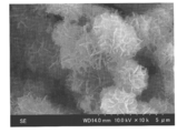
- FIG. 2 is a scanning electron micrograph (10,000 times) of the composite particles of Example 1.
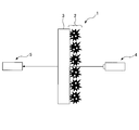
- FIG. FIG. 3 is a schematic view showing an optical device for measuring the light transmittance of the hydrogen detection member of Example 1. It is a figure which shows the measurement result of the light transmittance of the hydrogen detection member of Example 1.
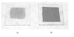
- FIG. It is the photograph before and behind detecting the hydrogen of the hydrogen detection member of Example 1.
- nanopalladium particles are attached to the surface of the nickel oxyhydroxide particles.
- the molar ratio of Pd to Ni in the composite particles is 0.01 to 0.03, preferably 0.15 to 0.025.
- hydrogen cannot be detected in a short time by visual observation, and when it exceeds 0.03, hydrogen cannot be detected by visual observation.
- the composite particles When the composite particles are exposed to an atmosphere containing hydrogen, nickel oxyhydroxide is reduced to nickel hydroxide by the catalytic action of nanopalladium particles adhering to the surface of the composite particles, and the wavelength ranges from 400 to 800 nm. Thus, the light transmittance or reflectance changes.
- the nickel oxyhydroxide particles are black.
- the particle diameter of the nickel oxyhydroxide particles is preferably 2 to 5 ⁇ m.
- the method for synthesizing the nickel oxyhydroxide particles is not particularly limited, and examples thereof include a chemical bath deposition method, a coprecipitation method, and a uniform precipitation method.
- Nickel oxyhydroxide particles can be synthesized by dropping an aqueous solution of a metal compound containing, an aqueous solution of potassium persulfate, and an aqueous solution of ammonium hydroxide.
- a sufficient amount of an aqueous solution of an alkali metal hydroxide is preferably added appropriately.
- the catalytic properties of nanopalladium particles are dramatically improved compared to normal palladium particles due to the increase in surface area accompanying the nanosize of the particle size.
- the number average particle diameter of the nanopalladium particles is preferably 20 to 40 nm.
- the nanopalladium particles preferably have a protective layer formed on the surface.
- the protective layer preferably contains a water-soluble polymer.
- the water-soluble polymer is not particularly limited, and examples thereof include polyvinyl pyrrolidone and polyol.
- the method for synthesizing the nanopalladium particles is not particularly limited, and examples thereof include a chemical reduction method and a solution method.
- reaction solution for example, in a reaction vessel at 70 ° C., an aqueous solution of a metal compound containing palladium as a main component, a water-soluble polymer as a material constituting the protective layer, and an aqueous solution of sodium hydroxide (NaOH) are reacted. By doing so, nanopalladium particles can be synthesized. At that time, the reaction solution is preferably made alkaline.
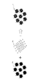
- FIG. 1 shows an example of a method for producing composite particles of the present embodiment.
- the composite particles 1 can be produced by mixing the nickel oxyhydroxide particles 1a and the nanopalladium particles 1b in a solvent.
- the solvent is not particularly limited, and examples thereof include water and ethanol. Among these, water is particularly preferable.
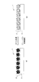
- FIG. 2 shows an example of the hydrogen detection member of this embodiment.
- the hydrogen detection member detects hydrogen by a change in optical properties, and a hydrogen detection film 2 including the composite particles 1 is formed on the substrate 3.
- the hydrogen detection film 2 changes in light transmittance or reflectance according to an atmosphere containing hydrogen to be exposed.
- the film thickness of the hydrogen detection film 2 is preferably 20 to 100 ⁇ m.
- the thickness of the hydrogen detection film 2 is 20 ⁇ m or more, the black color of the hydrogen detection film 2 is easily recognized by visual observation.
- the thickness is 100 ⁇ m or less, the white color of the hydrogen detection film 2 is easily recognized by visual observation.
- the hydrogen detection film 2 can be formed by a wet coating method.
- the wet coating method is not particularly limited, and examples thereof include a spin coating method, a spray coating method, a dip coating method, and a drop coating method.
- the hydrogen detection film 2 can be formed by a wet coating method, the hydrogen detection film 2 having a large surface area can also be formed at high speed. Further, since an expensive vacuum device or the like is not used, the hydrogen detection member of the present embodiment can be manufactured at a very low cost compared to the conventional hydrogen detection member.
- the material constituting the substrate 3 is not particularly limited, but is an oxide such as glass, quartz, sapphire, and lithium niobate, polymer such as polyethylene terephthalate (PET), and cellophane tape that transmits light in the visible light region. Examples thereof include metals and opaque plastics that reflect light in the visible light region.
- FIG. 3 shows an example of the hydrogen detection method of the present embodiment.
- the hydrogen detection film 2 is black in a state before detecting hydrogen (see FIG. 3A), but changes to white when hydrogen is detected by exposure to an atmosphere containing hydrogen (FIG. 3B). )reference). Therefore, the hydrogen detection member of the present embodiment has a greater contrast before and after hydrogen detection than the conventional hydrogen detection member, so that even when a small amount of hydrogen is contained in the atmosphere, hydrogen can be detected visually. .
- the hydrogen detection film 2 has a memory property that retains white color once it is detected and changes to white color. Therefore, even when hydrogen leakage has occurred in the past and then no longer occurs, hydrogen leakage can be visually confirmed. For this reason, a hydrogen detection member can be used for the use which detects a hydrogen leak. Furthermore, even if the hydrogen detection film 2 changes to white once, by treating with ozone (O 3 ), nickel hydroxide in the composite particles is oxidized to nickel oxyhydroxide and can be returned to black. . This makes it possible to reuse the hydrogen detection member.
- Example 1 ⁇ Synthesis of nickel oxyhydroxide particles> 1.0M and nickel (II) sulfate hexahydrate (NiSO 4 ⁇ 6H 2 O) aqueous solution of 25 ml, 0.25M potassium persulfate (K 2 S 2 O 8) with stirring an aqueous solution 18.25ml mixed, mixed A liquid was obtained.
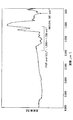
- FT-IR apparatus Frontier Fourier transform near-infrared / mid-infrared / far-infrared spectrometer (Perkin Elmer Japan) was used to measure the FT-IR spectrum of the composite particles.
- FIG. 4 shows the FT-IR spectrum of the composite particles.
- the X-ray photoelectron spectroscopy spectrum of the composite particles was measured using an X-ray photoelectron spectrometer Theta Probe Angle-Resolved Spectrometer system (manufactured by Thermo Fisher Scientific).
- FIG. 5 shows an X-ray photoelectron spectroscopy spectrum around Ni 2p of the composite particle.
- the composite particles had a molar ratio of Pd to Ni of 0.025.
- FIG. 6 shows an X-ray photoelectron spectrum around Pd 3d of the composite particle.
- the X-ray diffraction spectrum of the composite particles was measured using an X-ray diffractometer X'Pert-MRD (manufactured by Philip).
- FIG. 7 shows an X-ray diffraction spectrum of the composite particle.
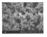
- FIG. 8 shows a scanning electron micrograph (2000 ⁇ magnification) of the composite particles.
- FIG. 8 shows that nickel oxyhydroxide particles having a particle diameter of about 2 to 3 ⁇ m are aggregated.
- FIG. 9 shows a scanning electron micrograph (10,000 times) of the composite particles.
- FIG. 9 shows that the individual nickel oxyhydroxide particles have irregular sheet flakes on the surface.
- 150 ⁇ l of the composite particle aqueous dispersion was drop-coated on a 3 cm ⁇ 3 cm silica glass substrate to form a hydrogen detection film having a thickness of 50 ⁇ m to obtain a hydrogen detection member.
- the light transmittance of the hydrogen detection member before and after being exposed to an atmosphere having a hydrogen content of 4% was measured using the optical apparatus shown in FIG.
- the optical device includes a light source 4 and a spectroscope 5, and a base material 3 on which a hydrogen detection film 2 is formed, that is, a hydrogen detection member is disposed between the light source 4 and the spectroscope 5 to transmit light. Measure the rate.
- FIG. 11 shows the measurement results of the light transmittance of the hydrogen detection member.
- FIG. 12 shows photographs before and after detecting the hydrogen of the hydrogen detection member.
- the hydrogen detection film was black (see FIG. 12B) before being exposed to the hydrogen atmosphere, but changed to white (see FIG. 12A) when exposed to the hydrogen atmosphere.
- the time required for the hydrogen detection film to change to white after being exposed to the hydrogen atmosphere that is, the time for visually detecting hydrogen was 3 minutes.
- the hydrogen detection film returned to black in 5 seconds when ozone treatment was performed under the conditions of an ozone output of 70 mg / h and an air flow rate of 5 L / min using an ozone generator Soec V350 (manufactured by Marco Co., Ltd.). For this reason, the hydrogen detection member can be reused.
- Composite particles and a hydrogen detection member were produced in the same manner as in Example 1 except that the amount of the nanopalladium particle dispersion added was changed to 0.1 ml.
- the composite particles had a molar ratio of Pd to Ni of 0.0015.
- Example 2 ⁇ Production of composite particles and hydrogen detection member> Composite particles and a hydrogen detection member were produced in the same manner as in Example 1 except that the amount of the nanopalladium particle dispersion added was changed to 0.5 ml. The composite particles had a molar ratio of Pd to Ni of 0.01.
- the hydrogen detection film was black before being exposed to an atmosphere containing hydrogen, but turned white when exposed to a hydrogen atmosphere. At this time, the hydrogen detection film had a time of 15 minutes for visually detecting hydrogen. Moreover, even if the hydrogen detection film was stopped from being exposed to the hydrogen atmosphere, it did not return to black and maintained white. On the other hand, the hydrogen detection film returned to black in 5 seconds when ozone treatment was performed under the conditions of an ozone output of 70 mg / h and an air flow rate of 5 L / min using an ozone generator Soec V350 (manufactured by Marco Co., Ltd.). For this reason, the hydrogen detection film can be reused.
- this embodiment relates to a hydrogen detection material, a hydrogen detection member, and a hydrogen detection method using a nickel oxyhydroxide-nanopalladium thin film, and according to this embodiment, heating is not required.
- a hydrogen detector that operates at room temperature can be produced.
- the hydrogen detection member of the present embodiment can be manufactured at low cost because its basic constituent material is inexpensive and an expensive noble metal material is used in a very small amount.
- this embodiment can be manufactured by a simple process using only a wet method and has a simple structure, it is possible to realize a hydrogen detector that is excellent in performance and inexpensive.
Landscapes
- Chemical & Material Sciences (AREA)
- Physics & Mathematics (AREA)
- Health & Medical Sciences (AREA)
- Life Sciences & Earth Sciences (AREA)
- Pathology (AREA)
- Analytical Chemistry (AREA)
- Biochemistry (AREA)
- General Health & Medical Sciences (AREA)
- General Physics & Mathematics (AREA)
- Immunology (AREA)
- Plasma & Fusion (AREA)
- Chemical Kinetics & Catalysis (AREA)
- Engineering & Computer Science (AREA)
- Molecular Biology (AREA)
- Investigating Or Analysing Materials By The Use Of Chemical Reactions (AREA)
- Investigating Or Analyzing Non-Biological Materials By The Use Of Chemical Means (AREA)
- Inorganic Compounds Of Heavy Metals (AREA)
Abstract
La présente invention concerne, dans un aspect, des particules composites, dans lesquelles des nano-particules de palladium sont liées à la surface de particules d'oxyhydroxyde de nickel, le rapport molaire de Pd sur Ni étant de 0,01 à 0,03.
Priority Applications (1)
| Application Number | Priority Date | Filing Date | Title |
|---|---|---|---|
| JP2017556471A JP6552015B2 (ja) | 2015-12-17 | 2016-12-16 | 複合粒子及びその製造方法 |
Applications Claiming Priority (2)
| Application Number | Priority Date | Filing Date | Title |
|---|---|---|---|
| JP2015-246332 | 2015-12-17 | ||
| JP2015246332 | 2015-12-17 |
Publications (1)
| Publication Number | Publication Date |
|---|---|
| WO2017104813A1 true WO2017104813A1 (fr) | 2017-06-22 |
Family
ID=59056646
Family Applications (1)
| Application Number | Title | Priority Date | Filing Date |
|---|---|---|---|
| PCT/JP2016/087581 Ceased WO2017104813A1 (fr) | 2015-12-17 | 2016-12-16 | Particules composites et leur procédé de fabrication |
Country Status (2)
| Country | Link |
|---|---|
| JP (1) | JP6552015B2 (fr) |
| WO (1) | WO2017104813A1 (fr) |
Citations (4)
| Publication number | Priority date | Publication date | Assignee | Title |
|---|---|---|---|---|
| JPS6039536A (ja) * | 1983-08-12 | 1985-03-01 | Hochiki Corp | ガスセンサ |
| JP2004053540A (ja) * | 2002-07-24 | 2004-02-19 | National Institute Of Advanced Industrial & Technology | マグネシウム薄膜を用いた水素センサ及び水素濃度測定方法 |
| JP2011112359A (ja) * | 2009-11-24 | 2011-06-09 | Figaro Engineerign Inc | SnO2ガスセンサの製造方法 |
| JP2016024001A (ja) * | 2014-07-18 | 2016-02-08 | 国立大学法人東北大学 | 新規な酸化第2スズ材料、及びその合成方法とガスセンサ材料 |
Family Cites Families (3)
| Publication number | Priority date | Publication date | Assignee | Title |
|---|---|---|---|---|
| US7700068B2 (en) * | 2006-07-19 | 2010-04-20 | Gm Global Technology Operations, Inc. | Method of making NiO and Ni nanostructures |
| KR20130047885A (ko) * | 2011-11-01 | 2013-05-09 | 강릉원주대학교산학협력단 | 산화수산화니켈-탄소나노튜브 나노복합체 전극의 제조 방법 |
| JP2013124897A (ja) * | 2011-12-14 | 2013-06-24 | Japan Atomic Energy Agency | 光学的水素ガス検知素子 |
-
2016
- 2016-12-16 WO PCT/JP2016/087581 patent/WO2017104813A1/fr not_active Ceased
- 2016-12-16 JP JP2017556471A patent/JP6552015B2/ja active Active
Patent Citations (4)
| Publication number | Priority date | Publication date | Assignee | Title |
|---|---|---|---|---|
| JPS6039536A (ja) * | 1983-08-12 | 1985-03-01 | Hochiki Corp | ガスセンサ |
| JP2004053540A (ja) * | 2002-07-24 | 2004-02-19 | National Institute Of Advanced Industrial & Technology | マグネシウム薄膜を用いた水素センサ及び水素濃度測定方法 |
| JP2011112359A (ja) * | 2009-11-24 | 2011-06-09 | Figaro Engineerign Inc | SnO2ガスセンサの製造方法 |
| JP2016024001A (ja) * | 2014-07-18 | 2016-02-08 | 国立大学法人東北大学 | 新規な酸化第2スズ材料、及びその合成方法とガスセンサ材料 |
Non-Patent Citations (2)
| Title |
|---|
| CHIH-WEI HU ET AL.: "Fabrication of nickel oxyhydroxide/palladium (NiOOH/Pd) nanocomposite for gasochromic application", SOLAR ENERGY MATERIALS & SOLAR CELLS, vol. 4, no. 23, 20 January 2017 (2017-01-20), pages 5390 - 5397, XP055373110 * |
| CHIH-WEI HU ET AL.: "Fabrication of nickel oxyhydroxide/palladium (NiOOH/Pd) thin films for gasochromic application", JOURNAL OF MATERIALS CHEMISTRY C, vol. 4, no. 23, 1 January 2016 (2016-01-01), pages 5390 - 5397, XP055373110 * |
Also Published As
| Publication number | Publication date |
|---|---|
| JPWO2017104813A1 (ja) | 2018-11-08 |
| JP6552015B2 (ja) | 2019-07-31 |
Similar Documents
| Publication | Publication Date | Title |
|---|---|---|
| Nakarungsee et al. | High performance Cr doped ZnO by UV for NH3 gas sensor | |
| Chava et al. | Enhanced H 2 gas sensing properties of Au@ In 2 O 3 core–shell hybrid metal–semiconductor heteronanostructures | |
| Lin et al. | Perovskite nanoparticle-sensitized Ga2O3 nanorod arrays for CO detection at high temperature | |
| US20120176681A1 (en) | Nanostructured anti-reflective coatings for substrates | |
| KR101734733B1 (ko) | 산화몰리브덴 기반 색가변 수소 검출센서 및 그 제조방법 | |
| Liu et al. | Enhanced visible light-excited ZnSnO3 for room temperature ppm-level CO2 detection | |
| Zhang et al. | Size-dependent response of hydrothermally grown SnO2 for a high-performance NO2 sensor and the impact of oxygen | |
| Singh et al. | A stable and highly sensitive room-temperature liquefied petroleum gas sensor based on nano-cubes/cuboids of zinc antimonate | |
| CN104609459B (zh) | 一种金包裹氧化锌花状微米球的制备方法 | |
| Narasimman et al. | Fiber-optic ammonia sensor based on amine functionalized ZnO nanoflakes | |
| JP2016075661A (ja) | 水素検出彩色センサー | |
| Cho et al. | High-sensitivity hydrogen gas sensors based on Pd-decorated nanoporous poly (aniline-co-aniline-2-sulfonic acid): poly (4-styrenesulfonic acid) | |
| Silva et al. | Simple hydrothermal synthesis method for tailoring the physicochemical properties of ZnO: morphology, surface area and polarity | |
| Prabhu et al. | Effect of Ni doping on the acetone vapor sensing performance of ZnO nanofibers | |
| Basso et al. | Sol–Gel Pt-VO2 Films as Selective Chemoresistive and Optical H2 Gas Sensors | |
| Narasimman et al. | Highly selective and rapid detection of ethanol using Ni-functionalized ZnO nanoflakes coated fiber optic sensor | |
| Wen et al. | On the origin of the surface superhydrophobicity of rough-textured inorganic materials with intrinsic hydrophilicity | |
| CN106698498B (zh) | 一种纳米氧化亚铜催化剂的制备方法 | |
| JP6552015B2 (ja) | 複合粒子及びその製造方法 | |
| US20230304954A1 (en) | Noble metal nanoparticle-decorated zinc oxide-on-metal gas sensor for ketone detection | |
| Shaw et al. | Ethanol gas sensors using semi-Hedgehog-like CuO nanostructures: studying the role of oxygen vacancies, unsaturated Cu-sites, and hole accumulation layer | |
| EP3647271B1 (fr) | Procédé de préparation d'une nanoparticule d'oxyde de nickel | |
| Arunachalam et al. | Facile synthesis of Mn doped ZnO for the sensing of ammonia | |
| Mariammal et al. | Role of heterojunction and oxygen vacancies on ethanol detection by ZnO: SnO2 nanocomposites | |
| Hu et al. | Facile Fabrication of Room-Temperature Parts-per-Billion-Level Acetone Sensor Driven by In Situ Laser-Induced Oxygen-Vacancy-Rich Cu/Cu2O/CuO Composites |
Legal Events
| Date | Code | Title | Description |
|---|---|---|---|
| 121 | Ep: the epo has been informed by wipo that ep was designated in this application |
Ref document number: 16875787 Country of ref document: EP Kind code of ref document: A1 |
|
| ENP | Entry into the national phase |
Ref document number: 2017556471 Country of ref document: JP Kind code of ref document: A |
|
| NENP | Non-entry into the national phase |
Ref country code: DE |
|
| 122 | Ep: pct application non-entry in european phase |
Ref document number: 16875787 Country of ref document: EP Kind code of ref document: A1 |