WO2017104895A1 - Structure d'ouverture et de fermeture automatique de cuiseur électrique - Google Patents
Structure d'ouverture et de fermeture automatique de cuiseur électrique Download PDFInfo
- Publication number
- WO2017104895A1 WO2017104895A1 PCT/KR2016/002005 KR2016002005W WO2017104895A1 WO 2017104895 A1 WO2017104895 A1 WO 2017104895A1 KR 2016002005 W KR2016002005 W KR 2016002005W WO 2017104895 A1 WO2017104895 A1 WO 2017104895A1
- Authority
- WO
- WIPO (PCT)
- Prior art keywords
- electric heating
- heating cooker
- driven gear
- gear
- closing structure
- Prior art date
- Legal status (The legal status is an assumption and is not a legal conclusion. Google has not performed a legal analysis and makes no representation as to the accuracy of the status listed.)
- Ceased
Links
Images


Classifications
-
- A—HUMAN NECESSITIES
- A47—FURNITURE; DOMESTIC ARTICLES OR APPLIANCES; COFFEE MILLS; SPICE MILLS; SUCTION CLEANERS IN GENERAL
- A47J—KITCHEN EQUIPMENT; COFFEE MILLS; SPICE MILLS; APPARATUS FOR MAKING BEVERAGES
- A47J27/00—Cooking-vessels
- A47J27/08—Pressure-cookers; Lids or locking devices specially adapted therefor
- A47J27/086—Pressure-cookers; Lids or locking devices specially adapted therefor with built-in heating means
Definitions
- the present invention relates to an automatic opening and closing structure of an electric heating cooker.
- the driven gear meshed with the drive gear consists of an internal gear, which increases the torque by increasing the reduction ratio compared to the installation space of the drive gear and the driven gear as compared to the case where the driven gear is an external gear. It relates to an automatic opening and closing structure of an electric heating cooker that can rotate.
- an electric heating cooker is an electric appliance that uses electricity as a heating source to perform various cooking, and includes an inner pot for receiving food (for example, rice, etc.), a main body for receiving the inner pot, and the main body.
- a lid for opening and closing an upper portion of the lid and an electric heating device for heating the inner pot may perform a function of generating a food such as rice in a edible form such as rice.
- the conventional electric heating cooker automatically rotates the locking wheel mounted on the lid by using a motor and a gear to make the lid closed or to complete the cooking so that the inner pot can be sealed when cooking.
- a structure that makes the lid open can be applied.
- the automatic opening and closing structure of a conventional electric heating cooker is an automatic locking device for an electric pressure cooker which automatically rotates a locking wheel mounted on a lid of the electric pressure cooker, and a motor unit driven by a change in current flow, and the motor unit. It is connected to the operating unit for rotating the locking wheel by using the driving force of the motor unit,
- the motor unit a rotor and a coil installed around the rotor, having a heat dissipation hole perforated on one side
- a gear box accommodating a coil case, at least one gear connected to the rotor, a drive shaft connected between the gear and the operating part to transmit rotational force of the rotor through the gear to the operating part, and the An outer case configured to be detachable from the coil case so as to close at least a part of the heat dissipation hole and not to seal the heat dissipation hole. It includes.
- the automatic opening / closing structure of the conventional electric heating cooker is composed of an external gear whose driven gear (operating lever) engaged with the driving gear is formed on the outer circumference thereof, thereby increasing the installation space of the driving gear and the driven gear (operating lever). There is this.
- the automatic opening and closing structure of the conventional electric heating cooker has a problem that it is difficult to rotate the locking wheel more smoothly and stably by increasing the torque applied to the locking wheel.
- the automatic opening and closing structure of the conventional electric heating cooker has a problem that the twist of the top cover may occur.
- the automatic opening and closing structure of the conventional electric heating cooker has a problem that friction and wear between the driven gear and the rotating shaft can easily occur.
- Patent Document 1 KR10-1555351 B1
- the driven gear meshing with the drive gear is made of an internal gear to increase the torque by increasing the reduction ratio compared to the installation space of the drive gear and the driven gear compared to the case where the driven gear is an external gear. It is an object of the present invention to provide an automatic opening and closing structure of an electric heating cooker capable of rotating the locking ring more smoothly and stably.
- the lock ring may include a motor, a driving gear rotating according to the operation of the motor, a driven gear engaged with the driving gear to rotate, and a first guide hole formed in the upper cover and extending in the driven gear. And a locking ring operating piece coupled to the driven gear, wherein the driven gear is an internal gear.
- a bracket is installed on one side of the lid, a rotating shaft is formed on one side of the bracket, the driven shaft is characterized in that the driven gear is fitted.
- a second guide hole is formed in the driven gear, and a guide bolt is inserted into the second guide hole to be fastened to the drive shaft of the drive gear.
- center of the drive gear is characterized in that disposed between the first guide hole and the rotating shaft.
- At least one oil groove is formed on the outer circumferential surface of the rotation shaft.
- the bracket is characterized in that it is installed to cover at least a portion of the upper portion of the motor.
- the bracket is characterized in that the groove is formed in the upper concave in the lower center, the flange is formed on one end and the other end, respectively.
- the automatic opening / closing structure of the electric heating cooker according to the present invention increases the reduction ratio compared to the installation space of the drive gear and the driven gear compared to the case where the driven gear is the external gear, thereby improving torque and smoothly and stably rotating the lock ring. There is an advantage.
- the automatic opening and closing structure of the electric heating cooker according to the present invention has the advantage of reducing friction and wear between the driven gear and the rotating shaft.
- the automatic opening and closing structure of the electric heating cooker according to the present invention has an advantage of preventing the top cover from twisting.
- FIG. 1 is a perspective view showing an electric heating cooker according to a preferred embodiment of the present invention.
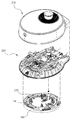
- Figure 2 is an exploded perspective view showing the lid of the electric heating cooker according to a preferred embodiment of the present invention.
- FIG. 3 is a perspective view illustrating a part of a state in which an upper cover and a lower cover of FIG. 2 are coupled;
- FIG. 4 is an exploded perspective view of FIG. 3;
- FIG. 5 is an enlarged perspective view showing the driven gear of FIG. 4 upside down.
- FIG. 1 is a perspective view showing an electric heating cooker 10 according to a preferred embodiment of the present invention
- Figure 2 is an exploded perspective view showing a lid 200 of the electric heating cooker 10 according to a preferred embodiment of the present invention
- 3 is a perspective view showing a part of a state in which the upper cover 220 and the lower cover 230 of FIG. 2 are coupled
- FIG. 4 is an exploded perspective view of FIG. 3
- FIG. 5 is a driven gear of FIG. An enlarged perspective view showing the inverted 350.
- the automatic opening and closing structure of the electric heating cooker 10 according to a preferred embodiment of the present invention, the lid of the electric heating cooker including an upper cover 220 and the lower cover 230.
- the main body 100 forms a lower portion of the external appearance of the electric heating cooker 10, and an inner pot is formed therein so that an inner pot (not shown) is accommodated.
- the lid 200 is installed above the main body 100.
- Lid 200 is hinged to the main body 100 serves to open and close the open upper portion of the main body 100.
- the lid 200 includes a lid case 210, an upper cover 220, and a lower cover 230.
- the lid case 210 forms an upper portion of the external appearance of the electric heating cooker, and a display unit (not shown) is formed on the upper surface so as to visually distinguish various states of the electric cooking cooker, or selectively operates an operation of the electric heating cooker.
- An operation unit (not shown) may be formed.
- An inner receiving space is formed in the lid case 210, and an upper cover 220 and a lower cover 230 are received and installed in the receiving space.
- the upper cover 220 is accommodated in the receiving space of the lid case 210 is fixedly installed, the lower cover 230 is fixedly installed on the lower portion of the upper cover 220, the inner pot at the lower portion of the lower cover 230 Inner pot lid (not shown) for sealing can be installed detachably.
- a circular locking ring 240 is installed between the upper cover 220 and the lower cover 230 to be rotated in a clockwise or counterclockwise direction with respect to the lower cover 230.
- the lock ring 240 is installed to seal the inner pot (not shown).
- a coupling protrusion 241 protruding upward is integrally formed at one upper side of the locking ring 240 and inserted from the lower side to the upper side in the first guide hole 225 formed in an arc shape convex toward the front cover 220. .
- Coupling protrusion 241 serves to rotate the locking ring 240 in accordance with the rotation of the locking ring operating piece 360 to be described later.
- a plurality of first locking parts are formed at a lower end of the inner circumferential surface of the lock ring 240 at predetermined intervals along the circumference of the lock ring 240.
- a plurality of first catching portions is a lower end of the plurality of second catching portions (not shown) formed in the inner pot (not shown) in accordance with the rotation of the lock ring 240 by the locking ring operating piece 360 to be described later.
- the inner pot (not shown) to be in contact with each other to seal the inner pot (not shown) so that the lid 200 does not open.
- the motor 310 and the gearbox 320 are fixed to the upper cover 220.
- the motor 310 is accommodated in the motor accommodating part 221 formed on the upper surface of the upper cover 220 is connected to the gear box 320 accommodated in the gear box accommodating part 223 to reduce the rotational force of the motor 310.
- the gear box 320 is formed such that the drive shaft 321 driven by the rotational force of the motor 310 protrudes upward, and the drive shaft 321 is fitted into the shaft fixing hole 331 of the drive gear 330 to drive the gear ( 330 is fixed to the drive shaft 321 to rotate in accordance with the operation of the motor 310. At this time, the drive shaft 321 and the drive gear 330 is rotated together.
- Brackets 340 are installed on the motor 310 and the gearbox 320 in the longitudinal direction. Bracket 340 is formed long in the left and right direction, is fixed to the upper cover 220 serves to reinforce the prevention of the twist of the upper cover 220, and also, the rotating shaft of the driven gear 350 to be described later ( 347).
- the bracket 340 is formed with a groove 341 concave upward in the lower center to accommodate a part of the motor 310 and the gearbox 320, the flange 343 formed on one end and the other end of the bracket 340, respectively
- the upper cover 220 is fastened with bolts and fixedly installed.
- the groove 341 is open at the lower portion and penetrates back and forth.
- the central portion of the bracket 340 is located above the flange 343.
- the bracket 340 is installed to cover a part of the motor 310 and the gearbox 320.
- a plurality of ribs 345 are formed on the upper surface of the bracket 340 to reinforce the bracket 340.
- a pivot shaft 347 protruding upward is integrally formed at the center of the upper surface of the bracket 340.
- the rotation shaft 347 is a portion into which the driven gear 350 to be described later is fitted.
- At least one oil groove 347a is formed on the outer circumferential surface of the rotation shaft 347 so that oil for reducing friction and wear between the rotation shaft 347 and the driven gear 350 to be described later may be introduced.
- the driven gear 350 is fitted to the rotation shaft 347.
- the driven gear 350 is installed to be engaged with the drive gear 330.
- the driven gear 350 is generally formed in a fan shape, and the front end portion, that is, a circular arc portion of the fan shape protrudes downward.
- the driven gear 350 has a gear 350a formed inside the circular arc-shaped portion protruding downward. That is, the driven gear 350 is formed of an internal gear, and the driving gear 330 is meshed with the driven gear 350.
- the reason why the driven gear 350 is formed of the internal gear is to reduce the installation space as compared with the case in which the driven gear is made of the external gear and meshes with the drive gear, and the driven gear is made of the external gear as in the prior art.
- the driven gear 350 has a rotation shaft 347 inserted into the shaft insertion hole 353 formed at the rear end side thereof in a clockwise or counterclockwise direction with respect to the rotation shaft 347 according to the rotation of the drive gear 330. Will be rotated. At this time, the rotation shaft 347 does not rotate with the driven gear 350 in a fixed state.
- An arc-shaped second guide hole 351 is formed near the center of the driven gear 350 in the forward direction.
- the guide bolt 351a is inserted into the second guide hole 351 to be inserted and fastened to the center of the drive gear 330, that is, to the center of the drive shaft 321.
- the second guide hole 351 is formed to accurately guide the rotation of the driven gear 350 based on the guide bolt 351a.
- the guide bolt 351a prevents the drive gear 330 and the driven gear 350 from being separated.
- the lock ring operating piece 360 is extended to the front side.
- the locking ring operating piece 360 is integrally formed at the center of the outer side of the fan-shaped circular arc portion projecting to the lower side of the driven gear 350 to rotate together with the rotation of the driven gear 350.
- the locking ring operating piece 360 has a trapezoidal shape on the front side as a whole and a rectangular shape on the rear side as a whole when viewed in plan.
- An insertion hole 361 having a long hole shape is formed near the center of the locking ring operating piece 360.
- Insertion hole 361 is coupled to the engaging projection 241 of the locking ring 240 protruding upward through the first guide hole 225 is inserted from the lower side to the upper side, the engaging projection 241 is a locking ring operating piece ( According to the rotation of the 360, the first guide hole 225 is guided and rotated. As a result, the lock ring 240 rotates together as the lock ring operating piece 360 rotates by the driven gear 350.
- Magnets 363 are provided at the front left and right sides of the insertion hole 361. The magnet 363 is detected by the sensing units 227 formed on the left and right sides of the first guide hole 225 to detect whether the lock ring 240 is in an open (unlocked) state or a closed (locked) state. It plays a role.
- the lock ring operating piece 360 rotates in a clockwise direction and the magnet 363 on the left side is adjacent to the sensing unit 227 on the left side, the lock ring 240 is detected to be open (unlocked).
- the locking ring operating piece 360 rotates counterclockwise and the magnet 363 on the right side is adjacent to the sensing unit 227 on the right side, the locking ring 240 may be detected to be closed (locked).
- the lock ring operating piece 360 rotates clockwise so that the magnet 363 on the left side is adjacent to the sensing unit 227 on the left side, the lock ring 240 is detected to be closed (locked).
- the locking ring operating piece 360 When the locking ring operating piece 360 rotates in a clockwise direction and the magnet 363 on the right side is adjacent to the sensing unit 227 on the right side, the locking ring 240 may be detected to be in an open (unlocked) state.
- a stopper 229 is formed between the left end of the first guide hole 225 and the sensing part of the left side and between the right end of the first guide hole 225 and the right sensing part of the first guide hole 225 to rotate the locking ring operating piece 360. Restrict.
- the center of the drive gear 330 that is, the drive shaft 321 is disposed between the first guide hole 225 and the rotation shaft 347. This is because the driven gear 350 is made of an internal gear, and thus the installation space can be reduced compared to when the dependent gear is an external gear.
- the lid 200 is automatically closed (locked) so as to seal the inner pot (not shown) when cooking, or the lid 200 is automatically opened when cooking is completed, such as cooking. It can be made as open as possible (unlocked).
- lid 210 lid case
- gear box accommodating part 225 first guide hole
- flange 345 rib
Landscapes
- Engineering & Computer Science (AREA)
- Food Science & Technology (AREA)
- Cookers (AREA)
Abstract
La présente invention concerne une structure d'ouverture et de fermeture automatiques d'un cuiseur électrique et, plus particulièrement, une structure d'ouverture et de fermeture automatiques d'un cuiseur électrique qui fait tourner automatiquement un anneau de verrouillage monté sur un couvercle du cuiseur électrique comprenant un couvercle supérieur et un couvercle inférieur et qui comprend un moteur, un engrenage d'entraînement qui tourne en fonction du fonctionnement du moteur, un engrenage entraîné qui tourne en prise avec l'engrenage d'entraînement et une pièce de fonctionnement d'anneau de verrouillage s'étendant à partir de l'engrenage entraîné et en prise avec l'anneau de verrouillage à travers un premier trou de guidage formé dans le couvercle supérieur, l'engrenage entraîné étant un engrenage interne et la structure pouvant ainsi faire tourner l'anneau de verrouillage de manière plus uniforme et stable.
Applications Claiming Priority (2)
| Application Number | Priority Date | Filing Date | Title |
|---|---|---|---|
| KR1020150180598A KR102368939B1 (ko) | 2015-12-17 | 2015-12-17 | 전기 가열 조리기의 자동 개폐 구조 |
| KR10-2015-0180598 | 2015-12-17 |
Publications (1)
| Publication Number | Publication Date |
|---|---|
| WO2017104895A1 true WO2017104895A1 (fr) | 2017-06-22 |
Family
ID=59056928
Family Applications (1)
| Application Number | Title | Priority Date | Filing Date |
|---|---|---|---|
| PCT/KR2016/002005 Ceased WO2017104895A1 (fr) | 2015-12-17 | 2016-02-29 | Structure d'ouverture et de fermeture automatique de cuiseur électrique |
Country Status (2)
| Country | Link |
|---|---|
| KR (1) | KR102368939B1 (fr) |
| WO (1) | WO2017104895A1 (fr) |
Cited By (15)
| Publication number | Priority date | Publication date | Assignee | Title |
|---|---|---|---|---|
| CN109984587A (zh) * | 2018-01-03 | 2019-07-09 | 佛山市顺德区美的电热电器制造有限公司 | 锅盖和具有其的烹饪器具 |
| CN109984581A (zh) * | 2018-01-03 | 2019-07-09 | 佛山市顺德区美的电热电器制造有限公司 | 烹饪器具和用于烹饪器具的上盖组件 |
| CN109984589A (zh) * | 2018-01-03 | 2019-07-09 | 佛山市顺德区美的电热电器制造有限公司 | 锅盖和具有其的烹饪器具 |
| US10390656B2 (en) | 2017-08-09 | 2019-08-27 | Sharkninja Operating Llc | Cooking device and components thereof |
| CN110393437A (zh) * | 2018-04-25 | 2019-11-01 | 佛山市顺德区美的电热电器制造有限公司 | 烹饪器具 |
| USD873602S1 (en) | 2018-08-09 | 2020-01-28 | Sharkninja Operating Llc | Lid part of a food preparation device |
| USD874211S1 (en) | 2018-08-09 | 2020-02-04 | Sharkninja Operating Llc | Food preparation device and parts thereof |
| USD903414S1 (en) | 2018-08-09 | 2020-12-01 | Sharkninja Operating Llc | Cooking basket |
| USD914436S1 (en) | 2018-06-19 | 2021-03-30 | Sharkninja Operating Llc | Air diffuser with food preparation pot |
| USD922126S1 (en) | 2019-06-06 | 2021-06-15 | Sharkninja Operating Llc | User interface for a food preparation device |
| US11033146B2 (en) | 2019-02-25 | 2021-06-15 | Sharkninja Operating Llc | Cooking device and components thereof |
| US11134808B2 (en) | 2020-03-30 | 2021-10-05 | Sharkninja Operating Llc | Cooking device and components thereof |
| USD934027S1 (en) | 2018-08-09 | 2021-10-26 | Sharkninja Operating Llc | Reversible cooking rack |
| USD934631S1 (en) | 2019-06-06 | 2021-11-02 | Sharkninja Operating Llc | Grill plate |
| US11751710B2 (en) | 2019-02-25 | 2023-09-12 | Sharkninja Operating Llc | Guard for cooking system |
Citations (5)
| Publication number | Priority date | Publication date | Assignee | Title |
|---|---|---|---|---|
| KR970061166A (ko) * | 1996-02-28 | 1997-09-12 | 배순훈 | 전기압력밥솥의 뚜껑 밀폐장치 |
| KR19980029119U (ko) * | 1996-11-27 | 1998-08-05 | 김용진 | 전기보온압력밥솥의 뚜껑 자동 개폐장치 |
| KR0170124B1 (ko) * | 1995-12-12 | 1999-01-15 | 배순훈 | 전기압력밥솥의 뚜껑 개폐장치 |
| KR20150136879A (ko) * | 2014-05-28 | 2015-12-08 | (주)쿠첸 | 전기압력밥솥을 위한 랙과 피니언 방식의 자동 잠금 장치 |
| KR20150136878A (ko) * | 2014-05-28 | 2015-12-08 | (주)쿠첸 | 전기압력밥솥의 자동 잠금장치 |
Family Cites Families (1)
| Publication number | Priority date | Publication date | Assignee | Title |
|---|---|---|---|---|
| KR101555351B1 (ko) | 2014-12-08 | 2015-09-23 | 주식회사 리홈쿠첸 | 전기압력밥솥의 자동 잠금장치 |
-
2015
- 2015-12-17 KR KR1020150180598A patent/KR102368939B1/ko not_active Expired - Fee Related
-
2016
- 2016-02-29 WO PCT/KR2016/002005 patent/WO2017104895A1/fr not_active Ceased
Patent Citations (5)
| Publication number | Priority date | Publication date | Assignee | Title |
|---|---|---|---|---|
| KR0170124B1 (ko) * | 1995-12-12 | 1999-01-15 | 배순훈 | 전기압력밥솥의 뚜껑 개폐장치 |
| KR970061166A (ko) * | 1996-02-28 | 1997-09-12 | 배순훈 | 전기압력밥솥의 뚜껑 밀폐장치 |
| KR19980029119U (ko) * | 1996-11-27 | 1998-08-05 | 김용진 | 전기보온압력밥솥의 뚜껑 자동 개폐장치 |
| KR20150136879A (ko) * | 2014-05-28 | 2015-12-08 | (주)쿠첸 | 전기압력밥솥을 위한 랙과 피니언 방식의 자동 잠금 장치 |
| KR20150136878A (ko) * | 2014-05-28 | 2015-12-08 | (주)쿠첸 | 전기압력밥솥의 자동 잠금장치 |
Cited By (76)
| Publication number | Priority date | Publication date | Assignee | Title |
|---|---|---|---|---|
| US11445856B2 (en) | 2017-08-09 | 2022-09-20 | Sharkninja Operating Llc | Cooking device and components thereof |
| US11399657B2 (en) | 2017-08-09 | 2022-08-02 | Sharkninja Operating Llc | Cooking device and components thereof |
| US11889950B2 (en) | 2017-08-09 | 2024-02-06 | Sharkninja Operating Llc | Cooking device and components thereof |
| US10390656B2 (en) | 2017-08-09 | 2019-08-27 | Sharkninja Operating Llc | Cooking device and components thereof |
| US10405697B2 (en) | 2017-08-09 | 2019-09-10 | Sharkninja Operating Llc | Cooking device and components thereof |
| US10405698B2 (en) | 2017-08-09 | 2019-09-10 | Sharkninja Operating Llc | Cooking device and components thereof |
| US10413121B2 (en) | 2017-08-09 | 2019-09-17 | Sharkninja Operating Llc | Cooking device and components thereof |
| US10413122B2 (en) | 2017-08-09 | 2019-09-17 | Sharkninja Operating Llc | Cooking device and components thereof |
| US11759049B2 (en) | 2017-08-09 | 2023-09-19 | Sharkninja Operating Llc | Cooking device and components thereof |
| US10485378B2 (en) | 2017-08-09 | 2019-11-26 | Sharkninja Operating Llc | Cooking device and components thereof |
| US11759048B2 (en) | 2017-08-09 | 2023-09-19 | Sharkninja Operating Llc | Cooking device and components thereof |
| US11627834B2 (en) | 2017-08-09 | 2023-04-18 | Sharkninja Operating Llc | Cooking system for cooking food |
| US11547243B2 (en) | 2017-08-09 | 2023-01-10 | Sharkninja Operating Llc | Cooking device and components thereof |
| US11547242B2 (en) | 2017-08-09 | 2023-01-10 | Sharkninja Operating Llc | Cooking device and components thereof |
| US11363910B2 (en) | 2017-08-09 | 2022-06-21 | Sharkninja Operating Llc | Cooking device and components thereof |
| US11109710B2 (en) | 2017-08-09 | 2021-09-07 | Sharkninja Operating Llc | Cooking device and components thereof |
| US11278151B2 (en) | 2017-08-09 | 2022-03-22 | Sharkninja Operating Llc | Cooking device and components thereof |
| US10646070B2 (en) | 2017-08-09 | 2020-05-12 | Sharkninja Operating Llc | Cooking device and components thereof |
| US10653270B2 (en) | 2017-08-09 | 2020-05-19 | Sharkninja Operating Llc | Cooking device and components thereof |
| US10660472B2 (en) | 2017-08-09 | 2020-05-26 | Sharkninja Operating Llc | Cooking device and components thereof |
| US10674868B2 (en) | 2017-08-09 | 2020-06-09 | Sharkninja Operating Llc | Cooking device and components thereof |
| US10682011B2 (en) | 2017-08-09 | 2020-06-16 | Sharkninja Operating Llc | Cooking device and components thereof |
| US11266267B2 (en) | 2017-08-09 | 2022-03-08 | Sharkninja Operating Llc | Cooking device and components thereof |
| US11266268B2 (en) | 2017-08-09 | 2022-03-08 | Sharkninja Operating Llc | Cooking device and components thereof |
| US11304561B2 (en) | 2017-08-09 | 2022-04-19 | Sharkninja Operating Llc | Cooking device and components thereof |
| US11089903B2 (en) | 2017-08-09 | 2021-08-17 | Sharkninja Operating Llc | Cooking device and components thereof |
| US11089902B2 (en) | 2017-08-09 | 2021-08-17 | Sharkninja Operating Llc | Cooking device and components thereof |
| CN109984587A (zh) * | 2018-01-03 | 2019-07-09 | 佛山市顺德区美的电热电器制造有限公司 | 锅盖和具有其的烹饪器具 |
| CN109984581A (zh) * | 2018-01-03 | 2019-07-09 | 佛山市顺德区美的电热电器制造有限公司 | 烹饪器具和用于烹饪器具的上盖组件 |
| CN109984589A (zh) * | 2018-01-03 | 2019-07-09 | 佛山市顺德区美的电热电器制造有限公司 | 锅盖和具有其的烹饪器具 |
| CN109984589B (zh) * | 2018-01-03 | 2021-02-26 | 佛山市顺德区美的电热电器制造有限公司 | 锅盖和具有其的烹饪器具 |
| CN109984587B (zh) * | 2018-01-03 | 2021-02-26 | 佛山市顺德区美的电热电器制造有限公司 | 锅盖和具有其的烹饪器具 |
| CN109984581B (zh) * | 2018-01-03 | 2021-12-21 | 佛山市顺德区美的电热电器制造有限公司 | 烹饪器具和用于烹饪器具的上盖组件 |
| CN110393437B (zh) * | 2018-04-25 | 2021-06-18 | 佛山市顺德区美的电热电器制造有限公司 | 烹饪器具 |
| CN110393437A (zh) * | 2018-04-25 | 2019-11-01 | 佛山市顺德区美的电热电器制造有限公司 | 烹饪器具 |
| USD914447S1 (en) | 2018-06-19 | 2021-03-30 | Sharkninja Operating Llc | Air diffuser |
| USD948938S1 (en) | 2018-06-19 | 2022-04-19 | Sharkninja Operating Llc | Air diffuser |
| USD914436S1 (en) | 2018-06-19 | 2021-03-30 | Sharkninja Operating Llc | Air diffuser with food preparation pot |
| USD873602S1 (en) | 2018-08-09 | 2020-01-28 | Sharkninja Operating Llc | Lid part of a food preparation device |
| USD929794S1 (en) | 2018-08-09 | 2021-09-07 | Sharkninja Operating Llc | Food preparation device |
| USD931680S1 (en) | 2018-08-09 | 2021-09-28 | Sharkninja Operating Llc | Cooking basket |
| USD903413S1 (en) | 2018-08-09 | 2020-12-01 | Sharkninja Operating Llc | Cooking basket |
| USD874211S1 (en) | 2018-08-09 | 2020-02-04 | Sharkninja Operating Llc | Food preparation device and parts thereof |
| USD934027S1 (en) | 2018-08-09 | 2021-10-26 | Sharkninja Operating Llc | Reversible cooking rack |
| USD929173S1 (en) | 2018-08-09 | 2021-08-31 | Sharkninja Operating Llc | Food preparation device |
| USD935259S1 (en) | 2018-08-09 | 2021-11-09 | Sharkninja Operating Llc | Food preparation device |
| USD940503S1 (en) | 2018-08-09 | 2022-01-11 | Sharkninja Operating Llc | Cooking basket |
| USD929793S1 (en) | 2018-08-09 | 2021-09-07 | Sharkninja Operating Llc | Food preparation device |
| USD941090S1 (en) | 2018-08-09 | 2022-01-18 | Sharkninja Operating Llc | Cooking basket |
| USD903415S1 (en) | 2018-08-09 | 2020-12-01 | Sharkninja Operating Llc | Cooking basket |
| USD876874S1 (en) | 2018-08-09 | 2020-03-03 | Sharkninja Operating Llc | User interface for a food preparation device |
| USD903414S1 (en) | 2018-08-09 | 2020-12-01 | Sharkninja Operating Llc | Cooking basket |
| USD883015S1 (en) | 2018-08-09 | 2020-05-05 | Sharkninja Operating Llc | Food preparation device and parts thereof |
| USD883014S1 (en) | 2018-08-09 | 2020-05-05 | Sharkninja Operating Llc | Food preparation device |
| USD883017S1 (en) | 2018-08-09 | 2020-05-05 | Sharkninja Operating Llc | User interface for food preparation device |
| USD883016S1 (en) | 2018-08-09 | 2020-05-05 | Sharkninja Operating Llc | Food preparation device and parts thereof |
| USD920732S1 (en) | 2018-08-09 | 2021-06-01 | Sharkninja Operating Llc | Food preparation device |
| US11766152B2 (en) | 2019-02-25 | 2023-09-26 | Sharkninja Operating Llc | Cooking device and components thereof |
| US11751710B2 (en) | 2019-02-25 | 2023-09-12 | Sharkninja Operating Llc | Guard for cooking system |
| US11832761B2 (en) | 2019-02-25 | 2023-12-05 | Sharkninja Operating Llc | Cooking device and components thereof |
| US11033146B2 (en) | 2019-02-25 | 2021-06-15 | Sharkninja Operating Llc | Cooking device and components thereof |
| US11147415B2 (en) | 2019-02-25 | 2021-10-19 | Sharkninja Operating Llc | Cooking device and components thereof |
| US11363911B2 (en) | 2019-02-25 | 2022-06-21 | Sharkninja Operating Llc | Cooking device and components thereof |
| US12226039B2 (en) | 2019-02-25 | 2025-02-18 | Sharkninja Operating Llc | Guard for cooking system |
| US11051654B2 (en) | 2019-02-25 | 2021-07-06 | Sharkninja Operating Llc | Cooking device and components thereof |
| US11751722B2 (en) | 2019-02-25 | 2023-09-12 | Sharkninja Operating Llc | Cooking device and components thereof |
| USD1054771S1 (en) | 2019-06-06 | 2024-12-24 | Sharkninja Operating Llc | Food preparation device |
| USD1049746S1 (en) | 2019-06-06 | 2024-11-05 | Sharkninja Operating Llc | Food preparation device |
| USD982375S1 (en) | 2019-06-06 | 2023-04-04 | Sharkninja Operating Llc | Food preparation device |
| USD934631S1 (en) | 2019-06-06 | 2021-11-02 | Sharkninja Operating Llc | Grill plate |
| USD922126S1 (en) | 2019-06-06 | 2021-06-15 | Sharkninja Operating Llc | User interface for a food preparation device |
| USD1015798S1 (en) | 2019-06-06 | 2024-02-27 | Sharkninja Operating Llc | Food preparation device |
| US11647861B2 (en) | 2020-03-30 | 2023-05-16 | Sharkninja Operating Llc | Cooking device and components thereof |
| US11969118B2 (en) | 2020-03-30 | 2024-04-30 | Sharkninja Operating Llc | Cooking device and components thereof |
| US11134808B2 (en) | 2020-03-30 | 2021-10-05 | Sharkninja Operating Llc | Cooking device and components thereof |
| US11678765B2 (en) | 2020-03-30 | 2023-06-20 | Sharkninja Operating Llc | Cooking device and components thereof |
Also Published As
| Publication number | Publication date |
|---|---|
| KR102368939B1 (ko) | 2022-03-03 |
| KR20170072449A (ko) | 2017-06-27 |
Similar Documents
| Publication | Publication Date | Title |
|---|---|---|
| WO2017104895A1 (fr) | Structure d'ouverture et de fermeture automatique de cuiseur électrique | |
| KR100878255B1 (ko) | 안전장치가 구비된 내솥 뚜껑 분리형 전기 압력 조리기 | |
| CN109480602A (zh) | 用于厨房用具的用于制备和/或烹饪食物的组件 | |
| EP2871276A1 (fr) | Machine à laver à tambour | |
| JP2005065371A (ja) | ギアードモータ | |
| CN110870678B (zh) | 烹饪器具及其锅盖组件 | |
| KR20150081948A (ko) | 전기조리기 | |
| CN205697177U (zh) | 电压力锅 | |
| CN209712624U (zh) | 烤箱 | |
| JP4217674B2 (ja) | 冷蔵庫扉の開閉構造 | |
| CN213551167U (zh) | 烹饪器具 | |
| CN106388568B (zh) | 家用电器结构、压力锅和电饭煲 | |
| CN201641568U (zh) | 电蒸炉旋钮式门锁 | |
| KR200349638Y1 (ko) | 미닫이창문 개폐장치 | |
| CN214142512U (zh) | 一种自动开关挡板的圆柱靶结构 | |
| CN216652054U (zh) | 一种水箱组件及其烹饪设备 | |
| CN110537847A (zh) | 沥水结构及烹饪装置 | |
| JP3615080B2 (ja) | 脱水兼用洗濯機 | |
| CN211093483U (zh) | 沥水结构及烹饪装置 | |
| CN220459137U (zh) | 烹饪器具 | |
| WO2019135429A1 (fr) | Dispositif de couvercle de batterie de cuisine permettant d'empêcher un débordement | |
| RU99112204A (ru) | Затвор для сращивания кабелей | |
| CN209472911U (zh) | 防水盒、线控器组件以及热水器 | |
| CN211006007U (zh) | 密封件、门体组件及衣物处理设备 | |
| CN217390456U (zh) | 锅盖组件及烹饪器具 |
Legal Events
| Date | Code | Title | Description |
|---|---|---|---|
| 121 | Ep: the epo has been informed by wipo that ep was designated in this application |
Ref document number: 16875837 Country of ref document: EP Kind code of ref document: A1 |
|
| NENP | Non-entry into the national phase |
Ref country code: DE |
|
| 122 | Ep: pct application non-entry in european phase |
Ref document number: 16875837 Country of ref document: EP Kind code of ref document: A1 |