WO2017109823A1 - Échangeur de chaleur et dispositif à cycle de réfrigération - Google Patents
Échangeur de chaleur et dispositif à cycle de réfrigération Download PDFInfo
- Publication number
- WO2017109823A1 WO2017109823A1 PCT/JP2015/085619 JP2015085619W WO2017109823A1 WO 2017109823 A1 WO2017109823 A1 WO 2017109823A1 JP 2015085619 W JP2015085619 W JP 2015085619W WO 2017109823 A1 WO2017109823 A1 WO 2017109823A1
- Authority
- WO
- WIPO (PCT)
- Prior art keywords
- tank space
- tank
- refrigerant
- flat tube
- heat exchanger
- Prior art date
- Legal status (The legal status is an assumption and is not a legal conclusion. Google has not performed a legal analysis and makes no representation as to the accuracy of the status listed.)
- Ceased
Links
Images



Classifications
-
- F—MECHANICAL ENGINEERING; LIGHTING; HEATING; WEAPONS; BLASTING
- F28—HEAT EXCHANGE IN GENERAL
- F28D—HEAT-EXCHANGE APPARATUS, NOT PROVIDED FOR IN ANOTHER SUBCLASS, IN WHICH THE HEAT-EXCHANGE MEDIA DO NOT COME INTO DIRECT CONTACT
- F28D1/00—Heat-exchange apparatus having stationary conduit assemblies for one heat-exchange medium only, the media being in contact with different sides of the conduit wall, in which the other heat-exchange medium is a large body of fluid, e.g. domestic or motor car radiators
- F28D1/02—Heat-exchange apparatus having stationary conduit assemblies for one heat-exchange medium only, the media being in contact with different sides of the conduit wall, in which the other heat-exchange medium is a large body of fluid, e.g. domestic or motor car radiators with heat-exchange conduits immersed in the body of fluid
- F28D1/04—Heat-exchange apparatus having stationary conduit assemblies for one heat-exchange medium only, the media being in contact with different sides of the conduit wall, in which the other heat-exchange medium is a large body of fluid, e.g. domestic or motor car radiators with heat-exchange conduits immersed in the body of fluid with tubular conduits
- F28D1/0408—Multi-circuit heat exchangers, e.g. integrating different heat exchange sections in the same unit or heat exchangers for more than two fluids
- F28D1/0426—Multi-circuit heat exchangers, e.g. integrating different heat exchange sections in the same unit or heat exchangers for more than two fluids with units having particular arrangement relative to the large body of fluid, e.g. with interleaved units or with adjacent heat exchange units in common air flow or with units extending at an angle to each other or with units arranged around a central element
- F28D1/0435—Combination of units extending one behind the other
-
- F—MECHANICAL ENGINEERING; LIGHTING; HEATING; WEAPONS; BLASTING
- F28—HEAT EXCHANGE IN GENERAL
- F28D—HEAT-EXCHANGE APPARATUS, NOT PROVIDED FOR IN ANOTHER SUBCLASS, IN WHICH THE HEAT-EXCHANGE MEDIA DO NOT COME INTO DIRECT CONTACT
- F28D1/00—Heat-exchange apparatus having stationary conduit assemblies for one heat-exchange medium only, the media being in contact with different sides of the conduit wall, in which the other heat-exchange medium is a large body of fluid, e.g. domestic or motor car radiators
- F28D1/02—Heat-exchange apparatus having stationary conduit assemblies for one heat-exchange medium only, the media being in contact with different sides of the conduit wall, in which the other heat-exchange medium is a large body of fluid, e.g. domestic or motor car radiators with heat-exchange conduits immersed in the body of fluid
- F28D1/04—Heat-exchange apparatus having stationary conduit assemblies for one heat-exchange medium only, the media being in contact with different sides of the conduit wall, in which the other heat-exchange medium is a large body of fluid, e.g. domestic or motor car radiators with heat-exchange conduits immersed in the body of fluid with tubular conduits
- F28D1/053—Heat-exchange apparatus having stationary conduit assemblies for one heat-exchange medium only, the media being in contact with different sides of the conduit wall, in which the other heat-exchange medium is a large body of fluid, e.g. domestic or motor car radiators with heat-exchange conduits immersed in the body of fluid with tubular conduits the conduits being straight
- F28D1/0535—Heat-exchange apparatus having stationary conduit assemblies for one heat-exchange medium only, the media being in contact with different sides of the conduit wall, in which the other heat-exchange medium is a large body of fluid, e.g. domestic or motor car radiators with heat-exchange conduits immersed in the body of fluid with tubular conduits the conduits being straight the conduits having a non-circular cross-section
- F28D1/05366—Assemblies of conduits connected to common headers, e.g. core type radiators
- F28D1/05391—Assemblies of conduits connected to common headers, e.g. core type radiators with multiple rows of conduits or with multi-channel conduits combined with a particular flow pattern, e.g. multi-row multi-stage radiators
-
- F—MECHANICAL ENGINEERING; LIGHTING; HEATING; WEAPONS; BLASTING
- F28—HEAT EXCHANGE IN GENERAL
- F28F—DETAILS OF HEAT-EXCHANGE AND HEAT-TRANSFER APPARATUS, OF GENERAL APPLICATION
- F28F1/00—Tubular elements; Assemblies of tubular elements
- F28F1/10—Tubular elements and assemblies thereof with means for increasing heat-transfer area, e.g. with fins, with projections, with recesses
- F28F1/12—Tubular elements and assemblies thereof with means for increasing heat-transfer area, e.g. with fins, with projections, with recesses the means being only outside the tubular element
- F28F1/24—Tubular elements and assemblies thereof with means for increasing heat-transfer area, e.g. with fins, with projections, with recesses the means being only outside the tubular element and extending transversely
- F28F1/32—Tubular elements and assemblies thereof with means for increasing heat-transfer area, e.g. with fins, with projections, with recesses the means being only outside the tubular element and extending transversely the means having portions engaging further tubular elements
-
- F—MECHANICAL ENGINEERING; LIGHTING; HEATING; WEAPONS; BLASTING
- F28—HEAT EXCHANGE IN GENERAL
- F28F—DETAILS OF HEAT-EXCHANGE AND HEAT-TRANSFER APPARATUS, OF GENERAL APPLICATION
- F28F19/00—Preventing the formation of deposits or corrosion, e.g. by using filters or scrapers
- F28F19/002—Preventing the formation of deposits or corrosion, e.g. by using filters or scrapers by using inserts or attachments
-
- F—MECHANICAL ENGINEERING; LIGHTING; HEATING; WEAPONS; BLASTING
- F28—HEAT EXCHANGE IN GENERAL
- F28F—DETAILS OF HEAT-EXCHANGE AND HEAT-TRANSFER APPARATUS, OF GENERAL APPLICATION
- F28F9/00—Casings; Header boxes; Auxiliary supports for elements; Auxiliary members within casings
- F28F9/02—Header boxes; End plates
- F28F9/0202—Header boxes having their inner space divided by partitions
-
- F—MECHANICAL ENGINEERING; LIGHTING; HEATING; WEAPONS; BLASTING
- F28—HEAT EXCHANGE IN GENERAL
- F28F—DETAILS OF HEAT-EXCHANGE AND HEAT-TRANSFER APPARATUS, OF GENERAL APPLICATION
- F28F9/00—Casings; Header boxes; Auxiliary supports for elements; Auxiliary members within casings
- F28F9/02—Header boxes; End plates
- F28F9/026—Header boxes; End plates with static flow control means, e.g. with means for uniformly distributing heat exchange media into conduits
- F28F9/0265—Header boxes; End plates with static flow control means, e.g. with means for uniformly distributing heat exchange media into conduits by using guiding means or impingement means inside the header box
-
- F—MECHANICAL ENGINEERING; LIGHTING; HEATING; WEAPONS; BLASTING
- F28—HEAT EXCHANGE IN GENERAL
- F28F—DETAILS OF HEAT-EXCHANGE AND HEAT-TRANSFER APPARATUS, OF GENERAL APPLICATION
- F28F2265/00—Safety or protection arrangements; Arrangements for preventing malfunction
- F28F2265/18—Safety or protection arrangements; Arrangements for preventing malfunction for removing contaminants, e.g. for degassing
Definitions
- the present invention relates to a heat exchanger and a refrigeration cycle apparatus including a plurality of heat exchange units.
- Patent Document 1 discloses a heat exchanger including a windward tube row and a leeward tube row, each of which is constituted by a plurality of flat tubes arranged in parallel and arranged in the air flow direction, and fins joined to the flat tubes.
- This heat exchanger has a one-to-one correspondence between the end portions of n (n is an integer of 2 or more) flat tubes constituting the windward tube row and the end portions of n flat tubes constituting the leeward tube row.
- a connection unit having n communication paths for communication is provided.
- the connection unit includes a second upwind header collecting pipe, a second downwind header collecting pipe, and n connecting pipes.
- the present invention has been made to solve the above-described problems, and provides a heat exchanger and a refrigeration cycle apparatus capable of reducing the cost of the refrigeration cycle apparatus and improving the reliability of the refrigeration cycle apparatus. Objective.
- the refrigeration cycle apparatus includes the heat exchanger according to the present invention.
- connection tank 205 It is a figure which shows the structure of a part of connection tank 205 between rows which concerns on Embodiment 2 of this invention. It is a figure which shows the structure of a part of connection tank 205 between rows which concerns on Embodiment 3 of this invention. It is a figure which shows the structure of a part of connection tank 205 between rows which concerns on Embodiment 4 of this invention.
- FIG. 1 is a refrigerant circuit diagram illustrating a configuration of a refrigeration cycle apparatus including a heat exchanger according to the present embodiment.
- the heat exchanger according to the present embodiment is used as the outdoor heat exchanger 101 of the refrigeration cycle apparatus 100, for example.
- the relative dimensional relationship and shape of each component may be different from the actual one.
- the installation posture of the component members and the positional relationship between the component members are, in principle, those when the heat exchanger and the refrigeration cycle apparatus are installed in a usable state. is there.
- the refrigeration cycle apparatus 100 includes an outdoor unit 102 and an indoor unit 103.
- the outdoor unit 102 is disposed, for example, outdoors, and the indoor unit 103 is disposed, for example, indoors.
- the outdoor unit 102 and the indoor unit 103 are connected to each other via a liquid side connection pipe 104 and a gas side connection pipe 105.
- the refrigeration cycle apparatus 100 includes a refrigerant circuit 106 formed by the outdoor unit 102, the indoor unit 103, the liquid side connection pipe 104, and the gas side connection pipe 105.
- the refrigerant circuit 106 is provided with a compressor 107, a four-way switching valve 108, an outdoor heat exchanger 101, an expansion valve 109 (an example of a decompression device), and an indoor heat exchanger 110.
- the compressor 107, the four-way switching valve 108, the outdoor heat exchanger 101, and the expansion valve 109 are accommodated in the outdoor unit 102.
- the outdoor unit 102 is provided with an outdoor blower fan 111 for supplying outdoor air to the outdoor heat exchanger 101.
- the indoor heat exchanger 110 is accommodated in the indoor unit 103.
- the indoor unit 103 is provided with an indoor fan 112 for supplying indoor air to the indoor heat exchanger 110.
- the discharge pipe of the compressor 107 is connected to the first port 108a of the four-way switching valve 108 via a refrigerant pipe.
- the suction pipe of the compressor 107 is connected to the second port 108b of the four-way switching valve 108 through a refrigerant pipe.
- the outdoor heat exchanger 101, the expansion valve 109, and the indoor heat exchanger 110 are connected between the third port 108c and the fourth port 108d of the four-way switching valve 108 via a refrigerant pipe. ing.
- the outdoor heat exchanger 101, the expansion valve 109, and the indoor heat exchanger 110 are arranged in this order from the third port 108c to the fourth port 108d.
- the refrigeration cycle apparatus 100 can execute a cooling operation and a heating operation by switching the flow path of the four-way switching valve 108.
- the high-pressure liquid refrigerant condensed in the indoor heat exchanger 110 is depressurized by the expansion valve 109, enters a gas-liquid two-phase state, and flows into the outdoor heat exchanger 101.
- the outdoor heat exchanger 101 operates as an evaporator.
- the low-pressure gas-liquid two-phase refrigerant that has flowed into the outdoor heat exchanger 101 is heated and evaporated by heat exchange with the air supplied by the outdoor blower fan 111.
- the low-pressure gas refrigerant evaporated in the outdoor heat exchanger 101 is sucked into the compressor 107 through the four-way switching valve 108.
- the four-way switching valve 108 is switched so that the first port 108a and the third port 108c communicate with each other and the second port 108b and the fourth port 108d communicate with each other.
- the refrigerant in the refrigerant circuit 106 flows in the opposite direction to that during the heating operation, the outdoor heat exchanger 101 operates as a radiator (in this example, a condenser), and the indoor heat exchanger 110 operates as an evaporator. To do.
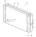
- FIG. 2 is a perspective view showing a schematic configuration of the heat exchanger according to the present embodiment.
- a thick arrow in FIG. 2 indicates the air flow direction.
- the outdoor heat exchanger 101 has a two-row structure in which two heat exchange units are arranged in series along the air flow direction.
- the outdoor heat exchanger 101 includes a windward heat exchange unit 201, a leeward heat exchange unit 202, a windward header collecting pipe 203, a leeward header collecting pipe 204, and an inter-column connection tank 205.
- Both the windward side heat exchanging part 201 and the leeward side heat exchanging part 202 exchange heat between the refrigerant and the air.
- the windward side heat exchange unit 201 and the leeward side heat exchange unit 202 are arranged to face each other.
- the windward side heat exchange unit 201 and the leeward side heat exchange unit 202 are arranged in series along the flow of air, and are arranged in series along the flow of refrigerant.
- the leeward heat exchange unit 202 is disposed downstream of the leeward heat exchange unit 201 in the air flow.
- the inter-column connection tank 205 has, for example, a rectangular tube shape that extends in the vertical direction and is closed at both ends.
- the inter-column connection tank 205 is disposed on the other side in the left-right direction of the windward side heat exchange unit 201 and the leeward side heat exchange unit 202, and connects the windward side heat exchange unit 201 and the leeward side heat exchange unit 202.
- the inter-row connection tank 205 includes a windward row of the outdoor heat exchanger 101 configured by the windward header collecting pipe 203 and the windward heat exchanging section 201, and a leeward heat exchanging section 202 and a leeward header collecting pipe 204. It arrange
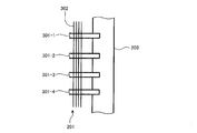
- FIG. 3 is a diagram showing a schematic configuration of a part of the windward heat exchange unit 201 and the windward header collecting pipe 203 according to the present embodiment.
- the windward heat exchange unit 201 has a plurality of flat tubes 301.
- the plurality of flat tubes 301 extend in the horizontal direction (left-right direction in FIG. 3), and are parallel to each other in the up-down direction.
- the number of flat tubes 301 is n (where n is an integer of 2 or more).
- FIG. 3 shows four flat tubes 301-1, 301-2, 301-3, and 301-4 when n flat tubes 301 are formed as flat tubes 301-1 to 301-n in order from the top. Yes.
- the windward side heat exchange unit 201 includes a plurality of plate-like fins 302 that intersect with each of the plurality of flat tubes 301.
- Each of the plurality of plate-like fins 302 is disposed along the air flow direction (the direction perpendicular to the paper surface in FIG. 3).
- Each of the plurality of flat tubes 301 is fixed to each of the plurality of plate-like fins 302 by brazing.
- One end side of each flat tube 301 in the extending direction is connected to the windward header collecting tube 203.
- Each flat tube 301 is inserted into the windward header collecting tube 203 and fixed to the windward header collecting tube 203 by brazing.
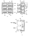
- FIG. 4 is a diagram showing a partial configuration of the inter-column connection tank 205 according to the present embodiment.
- FIG. 4 shows a configuration near the upper end of the inter-row connection tank 205.
- 4A shows the AA cross section of FIG. 4B
- FIG. 4B shows the BB cross section of FIG. 4A
- FIG. 4C shows FIG.
- the cross section CC of (b) is shown.
- the arrow in FIG.4 (c) represents the flow direction of the gas-liquid two-phase refrigerant
- the three flat tubes 401-1, 401-2, 401-3 are shown when the flat tubes 401 are changed to the flat tubes 401-1 to 401-n in order from the top.
- each tank space 208 is defined by the upper wall
- the lower end of each tank space 208 is defined by the lower wall.
- the upper surface wall of the tank space 208 positioned at the uppermost position in the inter-row connection tank 205 is the upper wall 205 b
- the lower wall of the tank space 208 is the partition wall 209.
- the upper surface wall of the tank space 208 positioned at the lowermost position in the inter-row connection tank 205 is a partition wall 209
- the lower wall of the tank space 208 is a lower wall of the inter-row connection tank 205.
- the upper wall and the lower wall of the other tank space 208 are both partition walls 209.
- the flat tube 301 has a flat shape in the air flow direction (left-right direction in FIG. 4A).
- the flat tube 301 is a multi-hole tube including a plurality of refrigerant channels 303 arranged in parallel in the flat direction.
- the flat tube 401 has a flat shape in the air flow direction.
- the flat tube 401 is a multi-hole tube including a plurality of refrigerant channels 403 arranged in parallel in the flat direction.
- the length L is, for example, 5 mm or more.
- each tank space 208 one end of the flat tube 301 and one end of the flat tube 401 are connected to the same height position, and the row direction in which the windward heat exchange unit 201 and the leeward heat exchange unit 202 are arranged in parallel ( It is parallel to the horizontal direction in FIG.
- the height of the upper surface wall (for example, the wall core of the upper surface wall) of the tank space 208 with respect to the lower surface wall (for example, the wall core of the lower surface wall) of the tank space 208 is X.
- the height of one end of the flat tube 301 with respect to the lower wall of the space 208 is Y1.
- X and Y1 are Y1 ⁇ (1/2) X Meet the relationship. That is, one end of the flat tube 301 and one end of the flat tube 401 are disposed below the center position in the vertical direction of each tank space 208.
- the outdoor heat exchanger 101 operates as an evaporator.
- the gas-liquid two-phase refrigerant decompressed by the expansion valve 109 of the refrigerant circuit 106 first flows into the windward header collecting pipe 203 of the outdoor heat exchanger 101 through the liquid side connecting pipe 206.
- the gas-liquid two-phase refrigerant that has flowed into the windward header collecting pipe 203 is divided into the plurality of flat tubes 301 of the windward heat exchange unit 201.
- the refrigerant flowing through the flat tube 301 is heated and evaporated by heat exchange with the air supplied by the outdoor blower fan 111.
- the gas-liquid two-phase refrigerant divided into the flat tube 301 becomes a gas-liquid two-phase refrigerant having a higher dryness than when flowing into the windward header collecting tube 203, and a plurality of tanks of the inter-column connection tank 205 are connected.
- the refrigerant flowing through the flat tube 401 is heated and evaporated by heat exchange with the air supplied by the outdoor blower fan 111.
- the gas-liquid two-phase refrigerant flowing through each flat tube 401 becomes a gas-liquid two-phase refrigerant or a gas single-phase refrigerant having a higher degree of dryness and merges in the leeward header collecting pipe 204.
- the state of the refrigerant in the tank space 208 will be described.
- the refrigerant flow in the tank space 208 is a gas-liquid two-phase flow.
- the liquid refrigerant having a relatively high density may stay in the dead space 210 in the tank space 208 under the influence of gravity.
- dot hatching is given to the dead space 210.
- the dead space 210 is a space below the refrigerant flow paths 303 and 403 of the flat tubes 301 and 401 in the tank space 208.
- the refrigeration oil that flows out of the compressor 107 together with the gas refrigerant may stay in the dead space 210 in the same manner as the liquid refrigerant.
- the heat exchanger includes the flat tube 301 through which the refrigerant is circulated, and the windward heat exchange unit 201 that performs heat exchange between the refrigerant and the air, and the windward heat exchange unit.
- the inter-row connection tank 205 connects the upper and lower walls (e.g., the upper wall 205b or the partition wall 209) and the lower wall (e.g., defining the upper and lower ends of the tank space 208, respectively).
- a partition wall 209 or a lower wall of the inter-row connection tank 205), and one end of the flat tube 301 and one end of the flat tube 401 are connected to the tank space 208, and the flat tube 301 is connected to the tank space 208.
- the end and one end of the flat tube 401 are arranged at the same height position, the height of the upper surface wall with respect to the lower surface wall is X, and the height of one end of the flat tube 301 with respect to the lower surface wall is Y1.
- X and Y1 satisfy the relationship of Y1 ⁇ (1/2) X.
- V1 and V2 may satisfy the relationship of V2 ⁇ (1/2) V1.
- the number of flat tubes 301 and flat tubes 401 connected to one tank space 208 may be one.
- the refrigeration cycle apparatus includes the heat exchanger according to the present embodiment.
- one end of the flat tube 301 connected to the tank space 208 and one end of the flat tube 401 are arranged below the center position in the vertical direction of the tank space 208.
- the amount of refrigerant charged in the refrigerant circuit 106 can be reduced, the amount of refrigerant released into the atmosphere is reduced even when the refrigerant leaks from the refrigerant pipe or the like. can do. Therefore, the environmental load of the refrigeration cycle apparatus 100 can be reduced.
- the present embodiment it is possible to prevent the refrigerating machine oil from being depleted in the compressor 107, so that the lubricity of the sliding portion of the compressor 107 can be maintained. Therefore, the reliability of the refrigeration cycle apparatus 100 can be improved.
- FIG. 6 is a diagram showing a partial configuration of the inter-column connection tank 205 according to the present embodiment.
- FIG. 6 shows a cross section corresponding to FIG. 4A of the inter-row connection tank 205.
- symbol is attached
- each tank space 208 in each tank space 208, one end of one flat tube 301 and one end of one flat tube 401 are connected.
- one flat tube 301-1 and one flat tube 401-1 are connected to the tank space 208 positioned at the top in the inter-row connection tank 205.
- the n flat tubes 301 and the n flat tubes 401 communicate with each other one to one through the n tank spaces 208.
- each of the flat tube 301 and the flat tube 401 is inserted through the cylindrical portion 205a by a length L (for example, 5 mm or more) into the tank space 208.
- the lower wall of each tank space 208 (for example, the partition wall 209 or the lower wall of the inter-row connection tank 205) has a thick portion 501 that partially increases the height of the bottom surface of the tank space 208. is doing.
- two thick portions 501 each having a flat inclined surface are disposed at both ends in the column direction (left-right direction in FIG. 6).
- the slope of the thick portion 501 may be curved instead of flat.
- the thick portion 501 may be formed separately from the lower wall of the tank space 208 or may be formed integrally with the lower wall of the tank space 208.
- the vertical arrangement positions of the flat tubes 301 and 401 connected to the tank space 208 are lower than the vertical center of the tank space 208 as in the first embodiment. It may be, or may be the center of the tank space 208 in the vertical direction or higher than that.
- the bottom wall of the tank space 208 (for example, the partition wall 209 or the lower wall of the inter-column connection tank 205) is the height of the bottom surface of the tank space 208.
- the volume of the dead space 210 formed in the lower part of the tank space 208 can be reduced, the amount of liquid refrigerant and refrigerating machine oil remaining in the tank space 208 can be reduced.
- coolant amount with which the refrigerant circuit 106 is filled can be reduced. Therefore, according to the present embodiment, the cost of the refrigeration cycle apparatus 100 can be reduced.
- the amount of refrigerant charged in the refrigerant circuit 106 can be reduced, the amount of refrigerant released to the atmosphere can be reduced even when the refrigerant leaks from the refrigerant pipe or the like. Therefore, according to the present embodiment, the environmental load of the refrigeration cycle apparatus 100 can be reduced.
- FIG. 7 is a diagram showing a partial configuration of the inter-column connection tank 205 according to the present embodiment.
- the cross section corresponding to FIG.4 (b) of the connection tank 205 between rows is shown.
- six flat tubes 301-1, 301-2, 301-3, 301-4, where n flat tubes 301 are formed as flat tubes 301-1 to 301-n in order from the top, 301-5 and 301-6 are shown.
- symbol is attached
- one end of a plurality of flat tubes 301 and one end of a plurality of flat tubes 401 are connected to the tank space 208 in the present embodiment.
- the tank space 208 positioned at the top in the inter-row connection tank 205, three flat tubes 301-1, 301-2, and 301-3 and three flat tubes 401-1 and 401-2 are provided. , 401-3.
- one end of the flat tubes 301-1, 301-2, and 301-3 and one end of the flat tubes 401-1, 401-2, and 401-3 are disposed at the same height position. ing.
- the height of one end (for example, the height of the central axis of the flat tube 301-3) is Y2.
- the arrangement pitch of the flat tubes 301 in the vertical direction is Z. At this time, Y2 and Z are Y2 ⁇ (1/2) Z Meet the relationship.
- the height of the upper surface wall (for example, the wall core of the upper surface wall) of the tank space 208 with respect to one end of the uppermost flat tube (for example, the flat tube 301-1) among the flat tubes 301 connected to the tank space 208. Is Y3.
- Y2 and Y3 are Y2 ⁇ Y3 Meet the relationship.
- the height of the upper surface wall (for example, the wall core of the upper surface wall) of the tank space 208 with respect to the lower surface wall (for example, the wall core of the lower surface wall) of the tank space 208 is Y4.
- Y4 in each of the plurality of tank spaces 208 has the same value.
- the tank space 208 includes one end of the plurality of flat tubes 301 arranged in the vertical direction and one end of the plurality of flat tubes 401 arranged in the vertical direction.
- the number of the flat tubes 301 and the flat tubes 401 connected to the tank space 208 is the same, and one end of the plurality of flat tubes 301 and one end of the plurality of flat tubes 401 are the tank space 208.
- the amount of liquid refrigerant and refrigeration oil remaining in the tank space 208 can be reduced. Therefore, according to the present embodiment, the amount of refrigerant charged in the refrigerant circuit 106 can be reduced, and the cost of the refrigeration cycle apparatus 100 can be reduced. Further, according to the present embodiment, since the amount of refrigerant charged in the refrigerant circuit 106 can be reduced, the amount of refrigerant released into the atmosphere is reduced even when the refrigerant leaks from the refrigerant pipe or the like. can do. Therefore, the environmental load of the refrigeration cycle apparatus 100 can be reduced.
- the present embodiment it is possible to prevent the refrigerating machine oil from being depleted in the compressor 107, so that the lubricity of the sliding portion of the compressor 107 can be maintained. Therefore, the reliability of the refrigeration cycle apparatus 100 can be improved.
- the upper wall of the tank space 208 (for example, the upper wall 205b) with respect to one end of the uppermost flat tube 301-1 among the plurality of flat tubes 301 connected to the tank space 208.
- the height of the partition wall 209) is Y3, Y2 and Y3 may satisfy the relationship of Y2 ⁇ Y3.
- the inter-column connection tank 205 can be manufactured using common components. Therefore, the productivity of the heat exchanger can be improved.
- FIG. 8 is a diagram showing a partial configuration of the inter-column connection tank 205 according to the present embodiment.
- FIG. 8 shows a cross section corresponding to FIG. 4A of the inter-row connection tank 205.
- symbol is attached
- the vertical arrangement of the flat tubes 301 and the vertical arrangement of the flat tubes 401 are shifted from each other by a half pitch. Thereby, the flat tubes 301 and 401 are arranged in a staggered pattern.
- each tank space 208 one end of one flat tube 301 and one end of one flat tube 401 are connected.
- one flat tube 301-1 and one flat tube 401-1 are connected to the tank space 208 positioned at the top in the inter-row connection tank 205.
- the height of one end of the flat tube 301-1 is lower by a half pitch than the height of one end of the flat tube 401-1.
- a part of the bottom surface of the tank space 208 is inclined in one direction according to the difference in height between the flat tubes 301 and 401.
- the lower wall of each tank space 208 (for example, the partition wall 209 or the lower wall of the inter-column connection tank 205) is horizontal or the lowest part of the bottom surface of the tank space 208 (for example, below the flat tube 401).
- a thick portion 502 having an R shape is provided. Thereby, the lowest part of the bottom surface of the tank space 208 is formed in a horizontal or R shape.
- the thick portion 502 may be formed separately from the lower wall of the tank space 208 or may be formed integrally with the lower wall of the tank space 208.
- the heat exchanger includes the flat tube 301 through which the refrigerant is circulated, and the windward heat exchange unit 201 that performs heat exchange between the refrigerant and the air, and the windward heat exchange unit.
- 201 a flat tube 401 through which a refrigerant flows, and a leeward heat exchange unit 202 that exchanges heat between the refrigerant and air, an upwind heat exchange unit 201, and a leeward heat exchange unit 202
- the inter-row connection tank 205 is connected to each other, and the inter-row connection tank 205 has a lower wall (for example, a partition wall 209 or a lower wall of the inter-row connection tank 205) that defines a lower end of the tank space 208.
- One end of the flat tube 301 and one end of the flat tube 401 are connected to the tank space 208, and one end of the flat tube 301 and one end of the flat tube 401 are at different height positions in the tank space 208. Connected Part of the bottom surface of the tank space 208 is inclined, the lowest part of the height of the bottom surface of the tank space 208 are those which are formed horizontally.
- the volume of the dead space 210 formed in the lower part of the tank space 208 can be reduced, the amount of liquid refrigerant and refrigerating machine oil remaining in the tank space 208 can be reduced.
- coolant amount with which the refrigerant circuit 106 is filled can be reduced. Therefore, according to the present embodiment, the cost of the refrigeration cycle apparatus 100 can be reduced.
- the amount of refrigerant charged in the refrigerant circuit 106 can be reduced, the amount of refrigerant released to the atmosphere can be reduced even when the refrigerant leaks from the refrigerant pipe or the like. Therefore, according to the present embodiment, the environmental load of the refrigeration cycle apparatus 100 can be reduced.
- the exhaust of the refrigeration oil in the compressor 107 can be prevented, the lubricity of the sliding portion of the compressor 107 can be maintained. Therefore, according to the present embodiment, the reliability of the refrigeration cycle apparatus 100 can be improved.
- the present invention is not limited to the above embodiment, and various modifications can be made.
- the heat exchanger having a two-row structure is taken as an example, but the present invention can also be applied to a heat exchanger having a multi-row structure of three or more rows.
- the outdoor heat exchanger 101 is taken as an example, but the heat exchanger of the present invention can also be applied to the indoor heat exchanger 110.
- 100 refrigeration cycle apparatus 101 outdoor heat exchanger, 102 outdoor unit, 103 indoor unit, 104 liquid side connection piping, 105 gas side connection piping, 106 refrigerant circuit, 107 compressor, 108 four-way switching valve, 108a first port, 108b 2nd port, 108c 3rd port, 108d 4th port, 109 expansion valve, 110 indoor heat exchanger, 111 outdoor blower fan, 112 indoor blower fan, 201 upwind heat exchanger, 202 downwind heat exchanger, 203 wind Upper header collecting pipe, 204 leeward header collecting pipe, 205 inter-row connection tank, 205a cylindrical part, 205b upper wall, 206 liquid side connecting pipe, 207 gas side connecting pipe, 208 tank space, 209 partition wall, 210 dead space , 301, 301-1, 301-2, 01-3, 301-4, 301-5, 301-6 flat tube, 302 plate fin, 303 refrigerant flow path, 401, 401-1, 401-2, 401-3, 401-4, 401-5, 401-6 flat
Landscapes
- Engineering & Computer Science (AREA)
- Physics & Mathematics (AREA)
- Thermal Sciences (AREA)
- Mechanical Engineering (AREA)
- General Engineering & Computer Science (AREA)
- Geometry (AREA)
- Heat-Exchange Devices With Radiators And Conduit Assemblies (AREA)
Abstract
Priority Applications (4)
| Application Number | Priority Date | Filing Date | Title |
|---|---|---|---|
| CN201580085442.3A CN108474632B (zh) | 2015-12-21 | 2015-12-21 | 热交换器及制冷循环装置 |
| JP2017557526A JP6570654B2 (ja) | 2015-12-21 | 2015-12-21 | 熱交換器及び冷凍サイクル装置 |
| PCT/JP2015/085619 WO2017109823A1 (fr) | 2015-12-21 | 2015-12-21 | Échangeur de chaleur et dispositif à cycle de réfrigération |
| US15/767,918 US10436514B2 (en) | 2015-12-21 | 2015-12-21 | Heat exchanger and refrigeration cycle apparatus |
Applications Claiming Priority (1)
| Application Number | Priority Date | Filing Date | Title |
|---|---|---|---|
| PCT/JP2015/085619 WO2017109823A1 (fr) | 2015-12-21 | 2015-12-21 | Échangeur de chaleur et dispositif à cycle de réfrigération |
Publications (1)
| Publication Number | Publication Date |
|---|---|
| WO2017109823A1 true WO2017109823A1 (fr) | 2017-06-29 |
Family
ID=59089723
Family Applications (1)
| Application Number | Title | Priority Date | Filing Date |
|---|---|---|---|
| PCT/JP2015/085619 Ceased WO2017109823A1 (fr) | 2015-12-21 | 2015-12-21 | Échangeur de chaleur et dispositif à cycle de réfrigération |
Country Status (4)
| Country | Link |
|---|---|
| US (1) | US10436514B2 (fr) |
| JP (1) | JP6570654B2 (fr) |
| CN (1) | CN108474632B (fr) |
| WO (1) | WO2017109823A1 (fr) |
Cited By (3)
| Publication number | Priority date | Publication date | Assignee | Title |
|---|---|---|---|---|
| JPWO2019193757A1 (ja) * | 2018-04-06 | 2020-10-22 | 三菱電機株式会社 | 熱交換器およびそれを備えた冷凍サイクル装置 |
| JP2020201020A (ja) * | 2019-06-13 | 2020-12-17 | ダイキン工業株式会社 | 熱交換器 |
| JP2021162216A (ja) * | 2020-03-31 | 2021-10-11 | 株式会社富士通ゼネラル | 熱交換器およびこれを備えた空気調和機 |
Families Citing this family (3)
| Publication number | Priority date | Publication date | Assignee | Title |
|---|---|---|---|---|
| JP6881624B1 (ja) * | 2020-01-22 | 2021-06-02 | 株式会社富士通ゼネラル | 熱交換器 |
| JP7292513B2 (ja) * | 2020-06-08 | 2023-06-16 | 三菱電機株式会社 | 熱交換器およびそれを用いた空気調和装置 |
| EP4235058A4 (fr) * | 2020-10-20 | 2024-01-10 | Mitsubishi Electric Corporation | Échangeur de chaleur et dispositif à cycle de réfrigération |
Citations (3)
| Publication number | Priority date | Publication date | Assignee | Title |
|---|---|---|---|---|
| JPS55131479U (fr) * | 1979-03-10 | 1980-09-17 | ||
| JPH04148195A (ja) * | 1990-10-09 | 1992-05-21 | Matsushita Refrig Co Ltd | 熱交換器 |
| WO2015046275A1 (fr) * | 2013-09-27 | 2015-04-02 | 三菱電機株式会社 | Échangeur thermique et appareil de climatisation utilisant cet échangeur thermique |
Family Cites Families (18)
| Publication number | Priority date | Publication date | Assignee | Title |
|---|---|---|---|---|
| US2419575A (en) * | 1945-03-05 | 1947-04-29 | Leonard Byram | Heater |
| US3173482A (en) * | 1962-11-21 | 1965-03-16 | American Air Filter Co | Quadrant baffle for heat exchange header |
| US4168742A (en) * | 1978-03-27 | 1979-09-25 | Hudson Products Corporation | Tube bundle |
| JP3051477B2 (ja) * | 1991-03-14 | 2000-06-12 | 昭和アルミニウム株式会社 | 熱交換器 |
| US5479985A (en) * | 1992-03-24 | 1996-01-02 | Nippondenso Co., Ltd. | Heat exchanger |
| TW552382B (en) * | 2001-06-18 | 2003-09-11 | Showa Dendo Kk | Evaporator, manufacturing method of the same, header for evaporator and refrigeration system |
| JP3960233B2 (ja) * | 2002-04-03 | 2007-08-15 | 株式会社デンソー | 熱交換器 |
| JP3736514B2 (ja) * | 2002-09-13 | 2006-01-18 | 三菱電機株式会社 | 熱交換器および熱交換器を用いた空気調和機 |
| US20110005271A1 (en) * | 2009-07-10 | 2011-01-13 | Keihin Corporation | Vehicular air conditioning apparatus |
| JP5687937B2 (ja) * | 2010-03-31 | 2015-03-25 | モーディーン・マニュファクチャリング・カンパニーModine Manufacturing Company | 熱交換器 |
| CN101832719A (zh) * | 2010-04-28 | 2010-09-15 | 苏州昆拓冷机有限公司 | 新型多通道换热器 |
| US9151540B2 (en) * | 2010-06-29 | 2015-10-06 | Johnson Controls Technology Company | Multichannel heat exchanger tubes with flow path inlet sections |
| US9651317B2 (en) * | 2011-01-21 | 2017-05-16 | Daikin Industries, Ltd. | Heat exchanger and air conditioner |
| EP2706318B1 (fr) * | 2011-05-06 | 2016-03-30 | Mitsubishi Electric Corporation | Échangeur de chaleur et dispositif à cycle de réfrigération équipé de cet échangeur |
| JP5609916B2 (ja) | 2012-04-27 | 2014-10-22 | ダイキン工業株式会社 | 熱交換器 |
| CN103256853A (zh) * | 2013-05-22 | 2013-08-21 | 江苏嘉和热系统股份有限公司 | 一种带限位结构的车用冷凝器 |
| JP6171766B2 (ja) * | 2013-09-11 | 2017-08-02 | ダイキン工業株式会社 | 熱交換器 |
| JP2015055413A (ja) | 2013-09-11 | 2015-03-23 | ダイキン工業株式会社 | 熱交換器 |
-
2015
- 2015-12-21 WO PCT/JP2015/085619 patent/WO2017109823A1/fr not_active Ceased
- 2015-12-21 US US15/767,918 patent/US10436514B2/en active Active
- 2015-12-21 JP JP2017557526A patent/JP6570654B2/ja active Active
- 2015-12-21 CN CN201580085442.3A patent/CN108474632B/zh not_active Expired - Fee Related
Patent Citations (3)
| Publication number | Priority date | Publication date | Assignee | Title |
|---|---|---|---|---|
| JPS55131479U (fr) * | 1979-03-10 | 1980-09-17 | ||
| JPH04148195A (ja) * | 1990-10-09 | 1992-05-21 | Matsushita Refrig Co Ltd | 熱交換器 |
| WO2015046275A1 (fr) * | 2013-09-27 | 2015-04-02 | 三菱電機株式会社 | Échangeur thermique et appareil de climatisation utilisant cet échangeur thermique |
Cited By (4)
| Publication number | Priority date | Publication date | Assignee | Title |
|---|---|---|---|---|
| JPWO2019193757A1 (ja) * | 2018-04-06 | 2020-10-22 | 三菱電機株式会社 | 熱交換器およびそれを備えた冷凍サイクル装置 |
| JP2020201020A (ja) * | 2019-06-13 | 2020-12-17 | ダイキン工業株式会社 | 熱交換器 |
| WO2020250624A1 (fr) * | 2019-06-13 | 2020-12-17 | ダイキン工業株式会社 | Échangeur de chaleur |
| JP2021162216A (ja) * | 2020-03-31 | 2021-10-11 | 株式会社富士通ゼネラル | 熱交換器およびこれを備えた空気調和機 |
Also Published As
| Publication number | Publication date |
|---|---|
| CN108474632A (zh) | 2018-08-31 |
| US10436514B2 (en) | 2019-10-08 |
| JPWO2017109823A1 (ja) | 2018-08-02 |
| US20180299203A1 (en) | 2018-10-18 |
| CN108474632B (zh) | 2020-01-07 |
| JP6570654B2 (ja) | 2019-09-04 |
Similar Documents
| Publication | Publication Date | Title |
|---|---|---|
| JP6570654B2 (ja) | 熱交換器及び冷凍サイクル装置 | |
| US9651317B2 (en) | Heat exchanger and air conditioner | |
| JP6091641B2 (ja) | 熱交換器、及び、空気調和装置 | |
| EP2930456B1 (fr) | Appareil d'échange thermique à tubes plats, et unité extérieure pour climatiseur le comportant | |
| JP6109303B2 (ja) | 熱交換器及び冷凍サイクル装置 | |
| US20160223231A1 (en) | Heat exchanger and air conditioner | |
| CN107429975A (zh) | 热交换器及空调机 | |
| JPWO2014115240A1 (ja) | 冷媒分配器及びこの冷媒分配器を用いたヒートポンプ装置 | |
| EP3156752B1 (fr) | Échangeur thermique | |
| WO2018173356A1 (fr) | Échangeur de chaleur et climatiseur faisant appel audit échangeur | |
| JP6120978B2 (ja) | 熱交換器及びそれを用いた空気調和機 | |
| US20250020420A1 (en) | Heat exchanger and air-conditioning apparatus | |
| JP2016050718A (ja) | 空気調和機 | |
| JP2018138826A (ja) | 空気調和装置 | |
| JP2020115070A (ja) | 熱交換器 | |
| WO2019130394A1 (fr) | Échangeur de chaleur et dispositif à cycle frigorifique | |
| JP6767606B1 (ja) | 分配装置、分配装置を備えた熱交換器およびその熱交換器を備えた空気調和機 | |
| US20230147134A1 (en) | Heat exchanger and air-conditioning apparatus | |
| JP7642170B1 (ja) | 熱交換器、熱交換器を備えた室外機、および、室外機を備えた空気調和装置 | |
| JP2021025747A (ja) | 熱交換器および空気調和機 | |
| JPWO2019155571A1 (ja) | 熱交換器および冷凍サイクル装置 | |
| JP2014126220A (ja) | 熱交換器 | |
| WO2023281656A1 (fr) | Échangeur de chaleur et dispositif à cycle frigorifique | |
| CN118339417A (zh) | 热交换器 | |
| JP2021025746A (ja) | 熱交換器および空気調和機 |
Legal Events
| Date | Code | Title | Description |
|---|---|---|---|
| 121 | Ep: the epo has been informed by wipo that ep was designated in this application |
Ref document number: 15911261 Country of ref document: EP Kind code of ref document: A1 |
|
| WWE | Wipo information: entry into national phase |
Ref document number: 15767918 Country of ref document: US |
|
| ENP | Entry into the national phase |
Ref document number: 2017557526 Country of ref document: JP Kind code of ref document: A |
|
| NENP | Non-entry into the national phase |
Ref country code: DE |
|
| 122 | Ep: pct application non-entry in european phase |
Ref document number: 15911261 Country of ref document: EP Kind code of ref document: A1 |