WO2017109881A1 - 情報処理装置、実装装置、情報処理方法及び部品把持具 - Google Patents
情報処理装置、実装装置、情報処理方法及び部品把持具 Download PDFInfo
- Publication number
- WO2017109881A1 WO2017109881A1 PCT/JP2015/085961 JP2015085961W WO2017109881A1 WO 2017109881 A1 WO2017109881 A1 WO 2017109881A1 JP 2015085961 W JP2015085961 W JP 2015085961W WO 2017109881 A1 WO2017109881 A1 WO 2017109881A1
- Authority
- WO
- WIPO (PCT)
- Prior art keywords
- component
- information processing
- mounting
- lead
- positioning
- Prior art date
- Legal status (The legal status is an assumption and is not a legal conclusion. Google has not performed a legal analysis and makes no representation as to the accuracy of the status listed.)
- Ceased
Links
Images



Classifications
-
- H—ELECTRICITY
- H05—ELECTRIC TECHNIQUES NOT OTHERWISE PROVIDED FOR
- H05K—PRINTED CIRCUITS; CASINGS OR CONSTRUCTIONAL DETAILS OF ELECTRIC APPARATUS; MANUFACTURE OF ASSEMBLAGES OF ELECTRICAL COMPONENTS
- H05K13/00—Apparatus or processes specially adapted for manufacturing or adjusting assemblages of electric components
- H05K13/04—Mounting of components, e.g. of leadless components
- H05K13/0404—Pick-and-place heads or apparatus, e.g. with jaws
- H05K13/0413—Pick-and-place heads or apparatus, e.g. with jaws with orientation of the component while holding it; Drive mechanisms for gripping tools, e.g. lifting, lowering or turning of gripping tools
-
- H—ELECTRICITY
- H05—ELECTRIC TECHNIQUES NOT OTHERWISE PROVIDED FOR
- H05K—PRINTED CIRCUITS; CASINGS OR CONSTRUCTIONAL DETAILS OF ELECTRIC APPARATUS; MANUFACTURE OF ASSEMBLAGES OF ELECTRICAL COMPONENTS
- H05K13/00—Apparatus or processes specially adapted for manufacturing or adjusting assemblages of electric components
- H05K13/04—Mounting of components, e.g. of leadless components
- H05K13/0404—Pick-and-place heads or apparatus, e.g. with jaws
- H05K13/0408—Incorporating a pick-up tool
-
- H—ELECTRICITY
- H05—ELECTRIC TECHNIQUES NOT OTHERWISE PROVIDED FOR
- H05K—PRINTED CIRCUITS; CASINGS OR CONSTRUCTIONAL DETAILS OF ELECTRIC APPARATUS; MANUFACTURE OF ASSEMBLAGES OF ELECTRICAL COMPONENTS
- H05K13/00—Apparatus or processes specially adapted for manufacturing or adjusting assemblages of electric components
- H05K13/0015—Orientation; Alignment; Positioning
-
- H—ELECTRICITY
- H05—ELECTRIC TECHNIQUES NOT OTHERWISE PROVIDED FOR
- H05K—PRINTED CIRCUITS; CASINGS OR CONSTRUCTIONAL DETAILS OF ELECTRIC APPARATUS; MANUFACTURE OF ASSEMBLAGES OF ELECTRICAL COMPONENTS
- H05K13/00—Apparatus or processes specially adapted for manufacturing or adjusting assemblages of electric components
- H05K13/04—Mounting of components, e.g. of leadless components
- H05K13/0417—Feeding with belts or tapes
- H05K13/0426—Feeding with belts or tapes for components being oppositely extending terminal leads
-
- H—ELECTRICITY
- H05—ELECTRIC TECHNIQUES NOT OTHERWISE PROVIDED FOR
- H05K—PRINTED CIRCUITS; CASINGS OR CONSTRUCTIONAL DETAILS OF ELECTRIC APPARATUS; MANUFACTURE OF ASSEMBLAGES OF ELECTRICAL COMPONENTS
- H05K13/00—Apparatus or processes specially adapted for manufacturing or adjusting assemblages of electric components
- H05K13/08—Monitoring manufacture of assemblages
- H05K13/081—Integration of optical monitoring devices in assembly lines; Processes using optical monitoring devices specially adapted for controlling devices or machines in assembly lines
- H05K13/0812—Integration of optical monitoring devices in assembly lines; Processes using optical monitoring devices specially adapted for controlling devices or machines in assembly lines the monitoring devices being integrated in the mounting machine, e.g. for monitoring components, leads, component placement
-
- H—ELECTRICITY
- H05—ELECTRIC TECHNIQUES NOT OTHERWISE PROVIDED FOR
- H05K—PRINTED CIRCUITS; CASINGS OR CONSTRUCTIONAL DETAILS OF ELECTRIC APPARATUS; MANUFACTURE OF ASSEMBLAGES OF ELECTRICAL COMPONENTS
- H05K13/00—Apparatus or processes specially adapted for manufacturing or adjusting assemblages of electric components
- H05K13/08—Monitoring manufacture of assemblages
- H05K13/081—Integration of optical monitoring devices in assembly lines; Processes using optical monitoring devices specially adapted for controlling devices or machines in assembly lines
- H05K13/0813—Controlling of single components prior to mounting, e.g. orientation, component geometry
-
- Y—GENERAL TAGGING OF NEW TECHNOLOGICAL DEVELOPMENTS; GENERAL TAGGING OF CROSS-SECTIONAL TECHNOLOGIES SPANNING OVER SEVERAL SECTIONS OF THE IPC; TECHNICAL SUBJECTS COVERED BY FORMER USPC CROSS-REFERENCE ART COLLECTIONS [XRACs] AND DIGESTS
- Y10—TECHNICAL SUBJECTS COVERED BY FORMER USPC
- Y10T—TECHNICAL SUBJECTS COVERED BY FORMER US CLASSIFICATION
- Y10T29/00—Metal working
- Y10T29/53—Means to assemble or disassemble
- Y10T29/5313—Means to assemble electrical device
- Y10T29/53174—Means to fasten electrical component to wiring board, base, or substrate
- Y10T29/53183—Multilead component
Definitions
- the present invention relates to an information processing device, a mounting device, an information processing method, and a component gripper.
- a mounting apparatus for example, horizontal light is applied to a limited part in the longitudinal direction of a lead having connector parts from a direction orthogonal to the longitudinal direction of the lead, and the tip of the lead is illuminated to position the lead. What is detected is disclosed (for example, refer to Patent Document 1). With this apparatus, the position of the lead can be detected quickly.
- Patent Document 1 can detect the position of the lead quickly, if the height of the lead or the shape of the lead tip changes, the lead tip cannot be reliably detected. There was a case.
- the present invention has been made in view of such a problem, and provides an information processing device, a mounting device, an information processing method, and a component gripper that can more reliably acquire the position of a gripped component. Main purpose.
- the present invention adopts the following means in order to achieve the main object described above.
- the information processing apparatus of the present invention An information processing apparatus used in a mounting apparatus for mounting a component on a board, The component is gripped by a component gripper having a positioning gripper that grips the component in a positioned state, a position of the component gripped by the positioning gripper, and a reference portion that represents a reference position that is a predetermined relative position.
- An image including at least the reference portion in a state of being acquired, acquiring the position of the reference portion based on the acquired image, and determining the position of the component based on the relative position with respect to the acquired position of the reference portion.
- Processing unit to acquire It is equipped with.
- an image of a component gripped by the positioning gripper is acquired, and the position of the component is determined by the relative position of the positioning gripper that positions and grips the component, not the component itself in the image. get. Therefore, in this apparatus, it is possible to acquire the position of the component without depending on the imaging state of the component, and it is possible to more reliably acquire the position of the gripped component.
- the component may include a lead, and the processing unit may acquire the position of the lead as the position of the component.
- the position of the lead of the component can be acquired more reliably.
- the insertion ratio of lead components when a lead is inserted and components are mounted can be further improved.
- the component includes a lead and a main body in which the lead is disposed, and the component gripping tool includes a groove portion in which the positioning grip portion receives and positions the lead, It is good also as what grasps the above-mentioned component by fitting the above-mentioned lead in a slot. In this apparatus, it is easy to position and grip the part by using the groove.
- the component may include a main body, and the component gripping tool may position and grip the component by a positioning grip unit that grips the main body from four directions.
- positioning can be performed by gripping the main body from four directions.
- the reference portion may be at least one of a tip surface of the positioning grip portion and a mark provided on the component gripper.
- the position of the gripped component can be acquired more reliably by using the tip surface or the mark of the positioning grip portion.
- the reference portion may be a color different from the background.
- background refers to an area around the reference portion in the captured image.
- the mounting apparatus of the present invention is A mounting head for mounting a component gripping tool including a positioning gripper that grips the component in a positioned state, a position of the component gripped by the positioning gripper, and a reference portion that represents a reference position that is a predetermined relative position; ,
- An information processing apparatus according to any one of the above, A control unit that causes the mounting head to mount the component on the substrate using the position of the component gripped by the component gripping tool acquired by the information processing apparatus; It is equipped with.
- This mounting device can acquire the position of the gripped component more reliably.
- the mounting apparatus includes any of the information processing apparatuses described above, it is possible to obtain an effect corresponding thereto.
- this mounting apparatus components can be more reliably mounted on the board.
- the information processing method of the present invention includes: An information processing method used in a mounting apparatus for mounting a component on a board, (A) a component gripper having a positioning gripper that grips the component in a positioned state, a position of the component gripped by the positioning gripper, and a reference portion that represents a reference position that is a predetermined relative position; Obtaining an image including at least the reference portion in a state where the object is gripped; (B) acquiring a position of the reference portion based on the acquired image; (C) acquiring the position of the component based on the relative position with respect to the acquired position of the reference portion; Is included.
- the position of the gripped component can be acquired more reliably.
- various aspects of the information processing apparatus described above may be adopted, and steps for realizing each function of the information processing apparatus described above may be added.
- the component gripping tool of the present invention includes a positioning gripping unit that grips the component in a positioned state, and a reference unit that represents a reference position that is a predetermined relative position with the position of the component gripped by the positioning gripping unit. Is. By using this component gripping tool in the information processing apparatus described above, the position of the gripped component can be acquired more reliably. In this component gripping tool, various aspects of the component gripping tool of the information processing apparatus described above may be adopted.
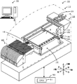
- FIG. 1 is a schematic explanatory diagram illustrating an example of a mounting system 10.
- FIG. The perspective view of the component holding tool 30.
- FIG. The flowchart showing an example of a mounting process routine.
- FIG. Explanatory drawing of the components holding tool 30 which is not holding the components 60.
- FIG. Explanatory drawing of the component holding tool 30 which is holding the component 60.
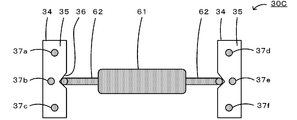
- Explanatory drawing of the component holding tool 30C which has the marks 37a-37f.
- FIG. 1 is a schematic explanatory diagram illustrating an example of the mounting system 10.
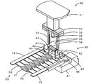
- FIG. 2 is an explanatory diagram of the component gripping tool 30 and the component supply unit 40.
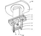
- FIG. 3 is a perspective view of the component gripping tool 30.
- the mounting system 10 is a system that executes a mounting process related to a process of mounting the component 60 on the board S.
- the mounting system 10 includes a mounting device 11 and a management computer 70. In FIG. 1, only one mounting apparatus 11 is shown for convenience of explanation. In the present embodiment, the left-right direction (X-axis), the front-rear direction (Y-axis), and the up-down direction (Z-axis) are as shown in FIG.
- the mounting apparatus 11 includes a board transfer unit 12, a mounting unit 13, a parts camera 15, a component supply unit 40, and a control device 50 (see FIG. 1).
- the substrate transport unit 12 is a unit that carries in, transports, fixes and unloads the substrate S at the mounting position.
- the substrate transport unit 12 has a pair of conveyor belts provided at intervals in the front-rear direction of FIG. 1 and spanned in the left-right direction. The board
- substrate S is conveyed by this conveyor belt.
- the mounting unit 13 collects the component 60 from the component supply unit 40 and arranges it on the substrate S fixed to the substrate transport unit 12.
- the mounting unit 13 includes a head moving unit 20, a mounting head 22, and a component gripping tool 30.
- the head moving unit 20 includes a slider that is guided by the guide rail and moves in the XY directions, and a motor that drives the slider.
- the mounting head 22 is detachably mounted on the slider and is moved in the XY direction by the head moving unit 20.
- a component gripping tool 30 is detachably mounted on the lower surface of the mounting head 22.
- the mounting head 22 incorporates a Z-axis motor 23, and this Z-axis motor 23 adjusts the height of the component gripper 30 along the Z-axis.
- the parts camera 15 images the component 60 collected by the mounting head 22 and is disposed in front of the board transfer unit 12.
- the parts camera 15 transmits the captured image to the control device 50.
- the captured image is used for determination of an abnormality in the shape of the component, a positional deviation of the collected component, and the like.
- the component gripping tool 30 is configured as a mechanical chuck that grips and samples the component 60, for example.
- the component 60 includes a columnar main body 61 and leads 62 disposed at both ends of the column.
- the lead 62 bent downward is inserted into a hole provided in the substrate S and then fixed by solder.
- the component supply unit 40 that supplies the component 60 and the component gripper 30 that collects the component 60 will be described as main examples.
- the component gripping tool 30 includes a mounting base 31, a fixed base 32, a positioning grip 34, a reference portion 35 (see FIG. 3), a groove 36, and a pressing portion 38. I have.
- the mounting base 31 is mounted on the lower surface of the mounting head 22, and a connection plate 33 is disposed below.
- the fixed base 32 is provided with a positioning grip 34 on the lower surface side.
- the fixed base 32 is fixed to the lower surface of the connection plate 33 with a screw so as not to move.
- the fixed base 32 can be slidably fixed in the longitudinal direction of the connection plate 33 so as to change the interval between the positioning grips 34.
- the positioning grip 34 is a pair of claw-shaped members that grip the component 60 in a positioned state.
- the positioning grip part 34 has a groove part 36 for receiving and positioning the lead 62.
- the groove 36 is a V-shaped groove formed on the opposing surfaces of the pair of positioning grips 34 in the vertical direction along the longitudinal direction of the positioning grips 34.
- the lead 62 abuts against the wall surface of the groove 36 by a spring force to spread, and its tip is always positioned at a predetermined position (see FIG. 7 described later).
- the reference portion 35 represents a reference position that is a predetermined relative position with the position of the component 60, and is a front end surface of the positioning grip portion 34.
- the reference unit 35 is, for example, a color different from the background of the image captured by the parts camera 15.
- the background is, for example, an area around the reference portion 35 in an image captured by the parts camera 15, for example, the main body of the fixed base 32, the connection plate 33, and the positioning grip portion 34.
- this background is colored with low luminance (for example, gray or black), and the reference portion 35 is colored with high luminance (for example, white or yellow).
- the reference unit 35 may have a contrast with the background so that it can be easily recognized, the background may be colored with high luminance, and the reference unit 35 may be colored with low luminance.
- the component gripping tool 30 positions the component 60 by fitting the lead 62 into the groove portion 36 of the positioning gripping portion 34, and grips the component 60 so as not to fall by the spring force of the lead 62.
- the component supply unit 40 includes a plurality of reels and is detachably attached to the front side of the mounting apparatus 11. A tape is wound around each reel, and a plurality of parts are held on the surface of the tape along the longitudinal direction of the tape. In the component 60, as shown in FIG. 2, the tips of linear leads 62 and 62 are fixed to the tapes 18 and 18. The tape 18 is unwound from the reel toward the rear, and is sent out by the transfer unit 41 to a sampling position where the component gripping tool 30 collects the component 60 with the component 60 exposed.
- the component supply unit 40 that supplies the component 60 includes a transfer portion 41, a support plate 42, a push-up portion 43, a bending plate 44, and a separation portion 45.
- the transfer unit 41 is a mechanism that sends out the tape 18 by a gear and a sprocket (not shown).
- the support plate 42 is a plate-like member that supports the lead 62 on both sides of the main body 61 and lifts the component 60 upward.
- the support plate 42 has a notch into which the lead 62 fits in the upper center.
- the push-up portion 43 is a member that is disposed between the support plates 42 and 42 and pushes up the main body 61 from below.
- the bending plate 44 is fixed to the housing of the component supply unit 40 and has a notch through which the lead 62 can pass on the side facing the support plate 42.
- the separation part 45 is a member that separates the tip end side of the lead 62 fixed to the tape 18.
- the support plate 42, the push-up portion 43, and the separation portion 45 are disposed on a pedestal (not shown) and move in the vertical direction together with the pedestal.
- the control device 50 is configured as a microprocessor centered on a CPU 51.
- the control device 50 outputs control signals to the substrate transport unit 12, the mounting unit 13, the parts camera 15, and the component supply unit 40, and inputs signals from the mounting unit 13, the parts camera 15, and the component supply unit 40. Further, the control device 50 stores information (for example, relative coordinates and distance) regarding the relative positional relationship between the reference portion 35 and the component 60 (the tip of the lead 62).
- the control device 50 acquires an image including at least the reference portion 35 in a state where the component 60 is gripped, acquires the position of the reference portion 35 based on the acquired image, and is relative to the acquired position of the reference portion 35. A process of acquiring the position of the component 60 based on the position is performed.
- the management computer 70 is a computer that manages information of each device of the mounting system 10.
- the management computer 70 includes an input device such as a keyboard and a mouse for an operator to input various commands, and a display for displaying various information.
- FIG. 4 is a flowchart illustrating an example of a mounting process routine executed by the CPU 51 of the control device 50.
- This routine is stored in the storage unit of the control device 50, and is executed by a start instruction from the operator.
- the CPU 51 of the control device 50 first determines whether it is time to correct the position of the mounting head 22 (step S100). As this timing, for example, at the time of starting the apparatus, after exchanging the tape 18 or at the time of restarting after an error stop, etc. may be mentioned. When it is the position correction timing, the CPU 51 causes the component gripper 30 to sample the component 60 and moves the sampled component 60 to the reference imaging position of the parts camera 15 (step S110).
- FIG. 5 is an explanatory diagram of the sampling process for the component 60.
- the component supply unit 40 moves the most advanced component 60 held on the tape 18 by the transfer unit 41 to above the support plate 42 and the push-up portion 43 (FIG. 5A).
- the initial positions of the support plate 42, the push-up portion 43, and the separation portion 45 are lower than the tape 18.
- the component supply unit 40 moves the support plate 42, the push-up portion 43, and the separation portion 45 upward.
- the component 60 is cut off from the tape 18 and the lead 62 held by the bending plate 44 is bent downward with the support plate 42 as a fulcrum while the lead 62 passes through the notch of the bending plate 44 (FIG. 5). (B)). Subsequently, the CPU 51 moves the component gripping tool 30 above the component 60 where the lead 62 is bent, and then lowers the component gripping tool 30 (FIG. 5C), and leads to the groove portion 36 of the positioning gripping portion 34. 62 is guided to cause the positioning grip 34 to grip the component 60.
- the component supply unit 40 may place the component gripper 30 at the sampling position of the component 60 before the support plate 42 is lifted, and cause the positioning gripper 34 to grip the component 60 together with the bending of the lead 62.
- the CPU 51 causes the parts camera 15 to capture an image including at least the reference unit 35 (step S120).
- the CPU 51 determines whether or not there is a component 60 in the captured image (step S130). That is, the CPU 51 determines whether or not the component gripping tool 30 has collected the component 60. This determination can be made based on, for example, whether the pixel value of the region where the component 60 should be present is the pixel value of the component 60 or the pixel value of the connection plate 33.
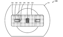
- FIG. 6 is an explanatory diagram of the component gripping tool 30 that does not grip the component 60.
- FIG. 7 is an explanatory diagram of the component gripping tool 30 that is gripping the component 60.
- the captured image is, for example, the image shown in FIG. 6 if there is no component 60, and the image shown in FIG. 7 if there is the component 60.
- the CPU 51 causes the processes after step S110 to be executed. At this time, the CPU 51 may display an error and stop the mounting process.
- the position of the reference unit 35 is acquired (step S140). In this processing, for example, binarization processing is performed on the region where the reference portion 35 should exist, edge detection is performed based on the displacement of the pixel value of each pixel, and the region of the pixel value corresponding to the reference portion 35 is extracted. The position (coordinates) of the reference unit 35 may be acquired.
- the CPU 51 acquires the position of the component 60 based on the acquired relative position with respect to the position of the reference unit 35 (step S150).
- the CPU 51 acquires the position of the lead 62 (tip surface) as the position of the component 60.
- the component 60 is gripped by the positioning grip 34 with the lead 62 fitted in the groove 36 of the positioning grip 34.
- the reference portion 35 is a tip surface of the positioning grip portion 34. Due to these relationships, the relative positional relationship between the reference portion 35 and the component 60 (the lead 62) is predetermined, so that the position of the tip surface of the lead 62 can be obtained from the position of the reference portion 35.
- the CPU 51 detects the amount of misalignment based on the relative position between the obtained position of the lead 62 and the regular reference position B (see FIG. 7), and corrects this misalignment.
- a correction value for correcting the position of is set (step S160). For example, the CPU 51 sets a correction value for correcting the positional deviation amount x in the X-axis direction and the positional deviation amount y in the Y-axis direction in FIG.
- step S160 the CPU 51 performs the mounting process of the component 60 using the set positional deviation correction value (step S170).
- the CPU 51 performs the following process. First, when the component 60 is not gripped by the component gripper 30, the CPU 51 performs steps S110 to S130 and collects the component 60 from the component supply unit 40. Next, the CPU 51 moves the mounting head 22 to a position where the component 60 is mounted on the substrate S, drives the Z-axis motor 23 to lower the component gripping tool 30, and further lowers the pressing portion 38 to move onto the substrate S.
- the component 60 is inserted and arranged in the box.
- the CPU 51 determines whether or not all the components 60 have been mounted on the substrate S (step S180), and when the mounting process is not completed, causes the processes after step S100 to be executed. On the other hand, when the mounting process is finished, this routine is finished as it is.
- the control device 50 of this embodiment corresponds to the processing unit and the information processing device of the present invention
- the component gripping tool 30 corresponds to the component gripping tool
- the positioning gripping portion 34 corresponds to the positioning gripping portion
- the reference portion 35 is the reference portion. It corresponds to the part.
- an example of the information processing method of the present invention is also clarified by describing the operation of the mounting apparatus 11.
- an image of the component 60 gripped by the positioning gripper 34 is acquired, and the positioning grip that positions and grips the component 60, not the component 60 itself in the image.
- the position of the component 60 is acquired from the relative positional relationship between the part 34 and the reference part 35.
- the tip surface of the lead 62 may not be flat or the height position of the tip surface may not be constant, and it is difficult to specify the tip surface of the lead 62 from the captured image with high accuracy. is there.
- the position of the component 60 can be acquired without depending on the imaging state of the component 60 by using the position of the reference portion 35, and thus the position of the gripped component 60 can be more reliably determined. Can be obtained.
- the mounting apparatus 11 can more reliably acquire the position of the lead 62 based on the position of the reference portion 35, and the lead component insertion rate when the component 62 is mounted by inserting the lead 62 into the substrate S. Can be further improved.
- the mounting apparatus 11 has a groove portion 36 in which the positioning grip portion 34 of the component gripper 30 accommodates and positions the lead 62, and the lead portion 62 fits into the groove portion 36 to grip the component 60. 36 makes it easy to position and grip the component 60.
- the reference portion 35 is the distal end surface of the positioning grip portion 34, the position of the gripped component 60 can be more reliably acquired by using the distal end surface of the positioning grip portion 34.
- standard part 35 is a color different from the connection board 33 etc. which are backgrounds, the control apparatus 50 is easy to recognize the reference
- the mounting apparatus 11 can more reliably acquire the position of the gripped component 60, so that the component 60 can be more reliably mounted on the substrate S.
- the component gripping tool 30 has been described as gripping the component 60 including the main body portion 61 and the lead 62.
- the component gripping tool 30 is particularly limited as long as the component can be gripped in a positioned state.
- the positioning grip 34 may be configured to position and grip the component 60 with a structure other than the groove 36.
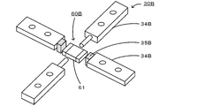
- the component may not have the lead 62, and the positioning grip portion 34 may not have the groove portion 36. At this time, as shown in FIG.
- the component 60 ⁇ / b> B has a main body 61
- the component gripping tool 30 ⁇ / b> B may position and grip the component 60 ⁇ / b> B by the positioning grip portion 34 ⁇ / b> B that grips the main body 61 from four directions.
- FIG. 8 is an explanatory diagram of another component gripping tool 30B.
- the component gripping tool 30B has a reference portion 35B at the tip of the positioning gripping portion 34B.
- the component gripping tool 30B can be positioned by gripping the main body from four directions.
- the reference portion 35 is the tip surface of the positioning grip portion 34, but is not particularly limited as long as the position can be specified by image recognition. Any one or more side portions may be used. Alternatively, in the component gripping tool 30, the reference portion 35 may be a mark provided at any location of the component gripping tool 30.
- FIG. 9 is an explanatory diagram of a component gripping tool 30C having marks 37a to 37f as reference portions. The component gripping tool 30C has circular marks 37a to 37f on the distal end surface of the positioning gripping portion 34. Note that the position and the number of marks are not particularly limited as long as they have a relative positional relationship with the tip position of the lead 62 and the tip position of the lead 62 can be grasped.
- the mark preferably has a shape and color that can be easily identified by image processing, and examples thereof include a circle, an ellipse, a rectangle, a polygon, and a star.
- the reference portion may be a combination of two or more of the mark, the tip surface, and the side portion of the member.
- control device 50 has been described as having the function of the information processing device according to the present invention.
- the present invention is not particularly limited thereto, and the control device 50 includes a processing unit separately from the control device 50 that controls the mounting process. Also good.
- the control unit of the management computer 70 may have the function of the information processing apparatus of the present invention.
- a plurality of control devices may be responsible for sharing the functions of the information processing apparatus of the present invention.
- control device 50 obtains the interval between the reference portions 35 and 35 from the acquired positions of the reference portions 35 and 35, and the correct component gripper 30 is mounted using this interval. It may be determined whether the head 22 is attached. By doing so, it is possible to prevent erroneous mounting in advance by using an incorrect component gripper.
- the present invention has been described as the mounting apparatus 11.
- the present invention may be the control apparatus 50, the present invention may be the component gripping tool 30, and the present invention may be an information processing method or the mounting apparatus 11.
- the present invention may be a control method, or the present invention may be a program that causes a computer to execute the processing described above.
- the present invention can be used for a mounting apparatus that arranges components on a substrate.
- 10 mounting system 11 mounting device, 12 substrate transport unit, 13 mounting unit, 15 parts camera, 18 tape, 20 head moving unit, 22 mounting head, 23 Z axis motor, 30, 30B, 30C component gripper, 31 mounting base , 32 fixed base, 33 connection plate, 34, 34B positioning gripping part, 35, 35B reference part, 36 groove part, 37a-37f mark, 38 pressing part, 40 parts supply unit, 41 transfer part, 42 support plate, 43 push-up part 44 bending plate, 45 cutting part, 50 control device, 51 CPU, 60, 60B parts, 61 main body part, 62 lead, 70 management computer, B reference position, S substrate.
Landscapes
- Engineering & Computer Science (AREA)
- Manufacturing & Machinery (AREA)
- Microelectronics & Electronic Packaging (AREA)
- Operations Research (AREA)
- Supply And Installment Of Electrical Components (AREA)
Abstract
Description
部品を基板に実装する実装装置に用いられる情報処理装置であって、
前記部品を位置決めした状態で把持する位置決め把持部と前記位置決め把持部に把持された前記部品の位置と所定の相対位置となる基準位置を表す基準部とを有する部品把持具により前記部品が把持された状態の少なくとも前記基準部を含む画像を取得し、前記取得した画像に基づいて前記基準部の位置を取得し、前記取得した基準部の位置との前記相対位置に基づいて前記部品の位置を取得する処理部、
を備えたものである。
前記部品を位置決めした状態で把持する位置決め把持部と前記位置決め把持部に把持された前記部品の位置と所定の相対位置となる基準位置を表す基準部とを有する部品把持具を装着する実装ヘッドと、
上述したいずれかに記載の情報処理装置と、
前記情報処理装置により取得された前記部品把持具に把持された前記部品の位置を用いて前記実装ヘッドに前記部品を前記基板へ実装させる制御部と、
を備えたものである。
部品を基板に実装する実装装置に用いられる情報処理方法であって、
(a)前記部品を位置決めした状態で把持する位置決め把持部と前記位置決め把持部に把持された前記部品の位置と所定の相対位置となる基準位置を表す基準部とを有する部品把持具により前記部品が把持された状態の少なくとも前記基準部を含む画像を取得するステップと、
(b)前記取得した画像に基づいて前記基準部の位置を取得するステップと、
(c)前記取得した基準部の位置との前記相対位置に基づいて前記部品の位置を取得するステップと、
を含むものである。
Claims (9)
- 部品を基板に実装する実装装置に用いられる情報処理装置であって、
前記部品を位置決めした状態で把持する位置決め把持部と前記位置決め把持部に把持された前記部品の位置と所定の相対位置となる基準位置を表す基準部とを有する部品把持具により前記部品が把持された状態の少なくとも前記基準部を含む画像を取得し、前記取得した画像に基づいて前記基準部の位置を取得し、前記取得した基準部の位置との前記相対位置に基づいて前記部品の位置を取得する処理部、
を備えた情報処理装置。 - 前記部品は、リードを有し、
前記処理部は、前記部品の位置として前記リードの位置を取得する、請求項1に記載の情報処理装置。 - 前記部品は、リードと該リードが配設された本体とを有し、
前記部品把持具は、前記位置決め把持部が前記リードを収容して位置決めする溝部を有し、該溝部に前記リードが嵌まることにより前記部品を把持する、請求項2に記載の情報処理装置。 - 前記部品は、本体を有し、
前記部品把持具は、前記本体を4方向から把持する位置決め把持部により前記部品を位置決めして把持する、請求項1に記載の情報処理装置。 - 前記基準部は、前記位置決め把持部の先端面及び前記部品把持具に設けられたマークのうち少なくとも一方である、請求項1~4のいずれか1項に記載の情報処理装置。
- 前記基準部は、背景と異なる色である、請求項1~5のいずれか1項に記載の情報処理装置。
- 前記部品を位置決めした状態で把持する位置決め把持部と前記位置決め把持部に把持された前記部品の位置と所定の相対位置となる基準位置を表す基準部とを有する部品把持具を装着する実装ヘッドと、
請求項1~6のいずれか1項に記載の情報処理装置と、
前記情報処理装置により取得された前記部品把持具に把持された前記部品の位置を用いて前記実装ヘッドに前記部品を前記基板へ実装させる制御部と、
を備えた実装装置。 - 部品を基板に実装する実装装置に用いられる情報処理方法であって、
(a)前記部品を位置決めした状態で把持する位置決め把持部と前記位置決め把持部に把持された前記部品の位置と所定の相対位置となる基準位置を表す基準部とを有する部品把持具により前記部品が把持された状態の少なくとも前記基準部を含む画像を取得するステップと、
(b)前記取得した画像に基づいて前記基準部の位置を取得するステップと、
(c)前記取得した基準部の位置との前記相対位置に基づいて前記部品の位置を取得するステップと、
を含む情報処理方法。 - 部品を位置決めした状態で把持する位置決め把持部と、前記位置決め把持部に把持された前記部品の位置と所定の相対位置となる基準位置を表す基準部と、を有する部品把持具。
Priority Applications (5)
| Application Number | Priority Date | Filing Date | Title |
|---|---|---|---|
| JP2017557574A JP6999422B2 (ja) | 2015-12-24 | 2015-12-24 | 実装装置及び実装方法 |
| CN201580085337.XA CN108370663B (zh) | 2015-12-24 | 2015-12-24 | 具备信息处理装置和元件把持用具的系统、具备信息处理装置和安装装置的系统、信息处理方法 |
| PCT/JP2015/085961 WO2017109881A1 (ja) | 2015-12-24 | 2015-12-24 | 情報処理装置、実装装置、情報処理方法及び部品把持具 |
| EP15911319.0A EP3397041B1 (en) | 2015-12-24 | 2015-12-24 | Information processing device, mounting device, information processing method, and component holding tool |
| US16/065,216 US11039559B2 (en) | 2015-12-24 | 2015-12-24 | Information processing apparatus, mounting apparatus, information processing method, and component gripper |
Applications Claiming Priority (1)
| Application Number | Priority Date | Filing Date | Title |
|---|---|---|---|
| PCT/JP2015/085961 WO2017109881A1 (ja) | 2015-12-24 | 2015-12-24 | 情報処理装置、実装装置、情報処理方法及び部品把持具 |
Publications (1)
| Publication Number | Publication Date |
|---|---|
| WO2017109881A1 true WO2017109881A1 (ja) | 2017-06-29 |
Family
ID=59089744
Family Applications (1)
| Application Number | Title | Priority Date | Filing Date |
|---|---|---|---|
| PCT/JP2015/085961 Ceased WO2017109881A1 (ja) | 2015-12-24 | 2015-12-24 | 情報処理装置、実装装置、情報処理方法及び部品把持具 |
Country Status (5)
| Country | Link |
|---|---|
| US (1) | US11039559B2 (ja) |
| EP (1) | EP3397041B1 (ja) |
| JP (1) | JP6999422B2 (ja) |
| CN (1) | CN108370663B (ja) |
| WO (1) | WO2017109881A1 (ja) |
Cited By (2)
| Publication number | Priority date | Publication date | Assignee | Title |
|---|---|---|---|---|
| CN109121378A (zh) * | 2018-09-26 | 2019-01-01 | 华勤通讯技术有限公司 | 组装定位治具和电子设备盲区组装方法 |
| US20230237667A1 (en) * | 2019-09-25 | 2023-07-27 | Fuji Corporation | Information processing device, mounting device, and information processing method |
Families Citing this family (1)
| Publication number | Priority date | Publication date | Assignee | Title |
|---|---|---|---|---|
| CN118893161B (zh) * | 2024-10-08 | 2025-02-11 | 宁波华兴伟业电子科技开发有限公司 | 一种精密元器件金属引脚剪切折弯设备 |
Citations (4)
| Publication number | Priority date | Publication date | Assignee | Title |
|---|---|---|---|---|
| JPS61501117A (ja) * | 1984-01-23 | 1986-05-29 | ダイナパ−ト プレシマ リミテツド | 電子部品取扱い用ピックアップヘッド |
| JPH0541598A (ja) * | 1991-05-10 | 1993-02-19 | Toshiba Corp | 部品実装位置補正方法 |
| JPH07170099A (ja) * | 1993-12-14 | 1995-07-04 | Matsushita Electric Ind Co Ltd | 電子部品挿入方法 |
| JP2014154841A (ja) * | 2013-02-13 | 2014-08-25 | Juki Corp | 電子部品実装装置および電子部品実装方法 |
Family Cites Families (6)
| Publication number | Priority date | Publication date | Assignee | Title |
|---|---|---|---|---|
| JPS6090690A (ja) * | 1983-10-21 | 1985-05-21 | ニチデン機械株式会社 | 電子部品の把持装置 |
| US4731923A (en) * | 1986-03-15 | 1988-03-22 | Tdk Corporation | Apparatus and method for mounting circuit element on printed circuit board |
| JP3387881B2 (ja) * | 1999-03-17 | 2003-03-17 | ティーディーケイ株式会社 | 電子部品挿入ヘッドおよび電子部品挿入装置 |
| JP2002094296A (ja) * | 2000-09-13 | 2002-03-29 | Fuji Mach Mfg Co Ltd | 吸着ノズル,電気部品の保持位置検出方法,吸着管曲がり検出方法,吸着ノズルの回転位置特定方法,電気部品取扱装置 |
| JP4576062B2 (ja) | 2001-03-21 | 2010-11-04 | 富士機械製造株式会社 | リード位置検出方法,電気部品装着方法およびリード位置検出装置 |
| JP6262736B2 (ja) | 2013-08-07 | 2018-01-17 | 富士機械製造株式会社 | 部品挿入機 |
-
2015
- 2015-12-24 US US16/065,216 patent/US11039559B2/en active Active
- 2015-12-24 EP EP15911319.0A patent/EP3397041B1/en active Active
- 2015-12-24 CN CN201580085337.XA patent/CN108370663B/zh active Active
- 2015-12-24 JP JP2017557574A patent/JP6999422B2/ja active Active
- 2015-12-24 WO PCT/JP2015/085961 patent/WO2017109881A1/ja not_active Ceased
Patent Citations (4)
| Publication number | Priority date | Publication date | Assignee | Title |
|---|---|---|---|---|
| JPS61501117A (ja) * | 1984-01-23 | 1986-05-29 | ダイナパ−ト プレシマ リミテツド | 電子部品取扱い用ピックアップヘッド |
| JPH0541598A (ja) * | 1991-05-10 | 1993-02-19 | Toshiba Corp | 部品実装位置補正方法 |
| JPH07170099A (ja) * | 1993-12-14 | 1995-07-04 | Matsushita Electric Ind Co Ltd | 電子部品挿入方法 |
| JP2014154841A (ja) * | 2013-02-13 | 2014-08-25 | Juki Corp | 電子部品実装装置および電子部品実装方法 |
Non-Patent Citations (1)
| Title |
|---|
| See also references of EP3397041A4 * |
Cited By (3)
| Publication number | Priority date | Publication date | Assignee | Title |
|---|---|---|---|---|
| CN109121378A (zh) * | 2018-09-26 | 2019-01-01 | 华勤通讯技术有限公司 | 组装定位治具和电子设备盲区组装方法 |
| US20230237667A1 (en) * | 2019-09-25 | 2023-07-27 | Fuji Corporation | Information processing device, mounting device, and information processing method |
| US12354276B2 (en) * | 2019-09-25 | 2025-07-08 | Fuji Corporation | Information processing device, mounting device, and information processing method |
Also Published As
| Publication number | Publication date |
|---|---|
| JP6999422B2 (ja) | 2022-01-18 |
| EP3397041A1 (en) | 2018-10-31 |
| US20180376633A1 (en) | 2018-12-27 |
| CN108370663B (zh) | 2021-06-29 |
| EP3397041B1 (en) | 2022-01-26 |
| CN108370663A (zh) | 2018-08-03 |
| EP3397041A4 (en) | 2018-12-26 |
| JPWO2017109881A1 (ja) | 2018-10-11 |
| US11039559B2 (en) | 2021-06-15 |
Similar Documents
| Publication | Publication Date | Title |
|---|---|---|
| EP3340760B1 (en) | Component mounting device | |
| JP6293899B2 (ja) | 実装装置 | |
| US10826262B2 (en) | Electronic equipment assembly apparatus and electronic equipment assembly method | |
| CN105453717A (zh) | 引脚位置检测装置及元件插入机 | |
| WO2015001599A1 (ja) | フィーダ調整装置 | |
| WO2019180954A1 (ja) | 部品装着装置 | |
| JPWO2017179146A1 (ja) | 実装装置及び実装方法 | |
| JP6828223B2 (ja) | 実装装置 | |
| JP6999422B2 (ja) | 実装装置及び実装方法 | |
| WO2019175980A1 (ja) | 採取治具及び実装装置 | |
| JP2017216311A (ja) | 部品実装装置および部品実装方法 | |
| JP7365324B2 (ja) | 実装装置 | |
| JP2017073431A (ja) | 画像認識装置 | |
| JP6673900B2 (ja) | 実装装置及び実装方法 | |
| JP6861335B2 (ja) | 部品実装装置および部品実装方法 | |
| CN110383969B (zh) | 元件安装机 | |
| CN105592684B (zh) | 电子部件安装装置 | |
| JPWO2019180953A1 (ja) | 部品装着装置 | |
| JP6204996B2 (ja) | 実装装置及び保持部材 | |
| JP6423193B2 (ja) | 実装装置及び実装方法 | |
| WO2018173226A1 (ja) | 実装装置及び実装方法 | |
| CN117480876A (zh) | 元件安装机及校正处理的控制方法 | |
| JP2018037591A (ja) | 実装装置 |
Legal Events
| Date | Code | Title | Description |
|---|---|---|---|
| 121 | Ep: the epo has been informed by wipo that ep was designated in this application |
Ref document number: 15911319 Country of ref document: EP Kind code of ref document: A1 |
|
| ENP | Entry into the national phase |
Ref document number: 2017557574 Country of ref document: JP Kind code of ref document: A |
|
| NENP | Non-entry into the national phase |
Ref country code: DE |
|
| WWE | Wipo information: entry into national phase |
Ref document number: 2015911319 Country of ref document: EP |
|
| ENP | Entry into the national phase |
Ref document number: 2015911319 Country of ref document: EP Effective date: 20180724 |